

Page 1
BOILER
Installation/Ope ra t or’s Manual
SAFETY NOTICE
Please read entire manual before installation and use of this pellet fuelburning boiler. Failure to follow these instructions could result in property
damage, bodily injury or even death. Contact local building or fire
officials about restrictions and installation inspection requirements in
your area.
SAVE THESE INSTRUCTIONS
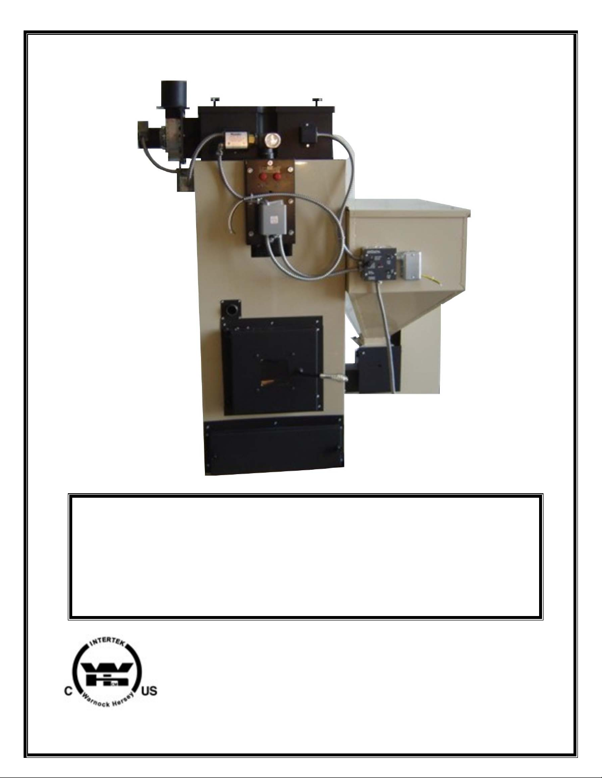
PINNACLE PB150
PELLET/CORN
PINNACLE STOVE SALES INC
1089 HIGHWAY 97 NORTH
QUESNEL, BC V2J 7C9
TEL. (250) 992-5050
FAX. (250) 992-5850
Page 2

1
TABLE OF CONTENTS
Page
SPECIFICATIONS
2
SPECIFICATIONS DIAGRAM figure 1
3
INSTALLATION REQUIREMENTS AND CLEARANCES
4-5
BURNER AND CONTROLS
6
SEQUENCE OF OPERATION
6
PRIMARY CONTROL
7
FUNCTIONING OF SAFETY AND OPERATING CONTROLS
8
VENTING
9-11
VENT TERMINATION REQUIREMNETS figure 2
11
DAMPER CONTROLS
11
WARNING ABOUT CHIMNEY FIRES
12
DOMESTIC WATER SYSTE M-DIAGRAM figure 3
13
DOMESTIC WATER COIL REQUIREMENTS figure 4
14
PARALLEL SYSTEM-DIAGRAM figure 5
16
SYSTEM IN SERIES-DIAGRAM figure 6
16
WIRING INFORMATION
17
WIRING DIAGRAM figure 7
19
BURNING CORN
19
START-UP INSTRUCTIONS
20
FUEL REQUIREMENTS
21
MAINTANANCE figure 8
22
ALTERNATE CONNECTIONS
23
WARRANTY
24
TROUBLE SHOOTING
25-27
PARTS LIST figure 9
28
NOTES
29
Page 3

2
BOILER SPECIFICATIONS
BTU INPUT ------------------------------------- 85,000 TO 130,000 BTU/HR
EFFICIENCY (HEAT TRANSFER) --------------- 80%
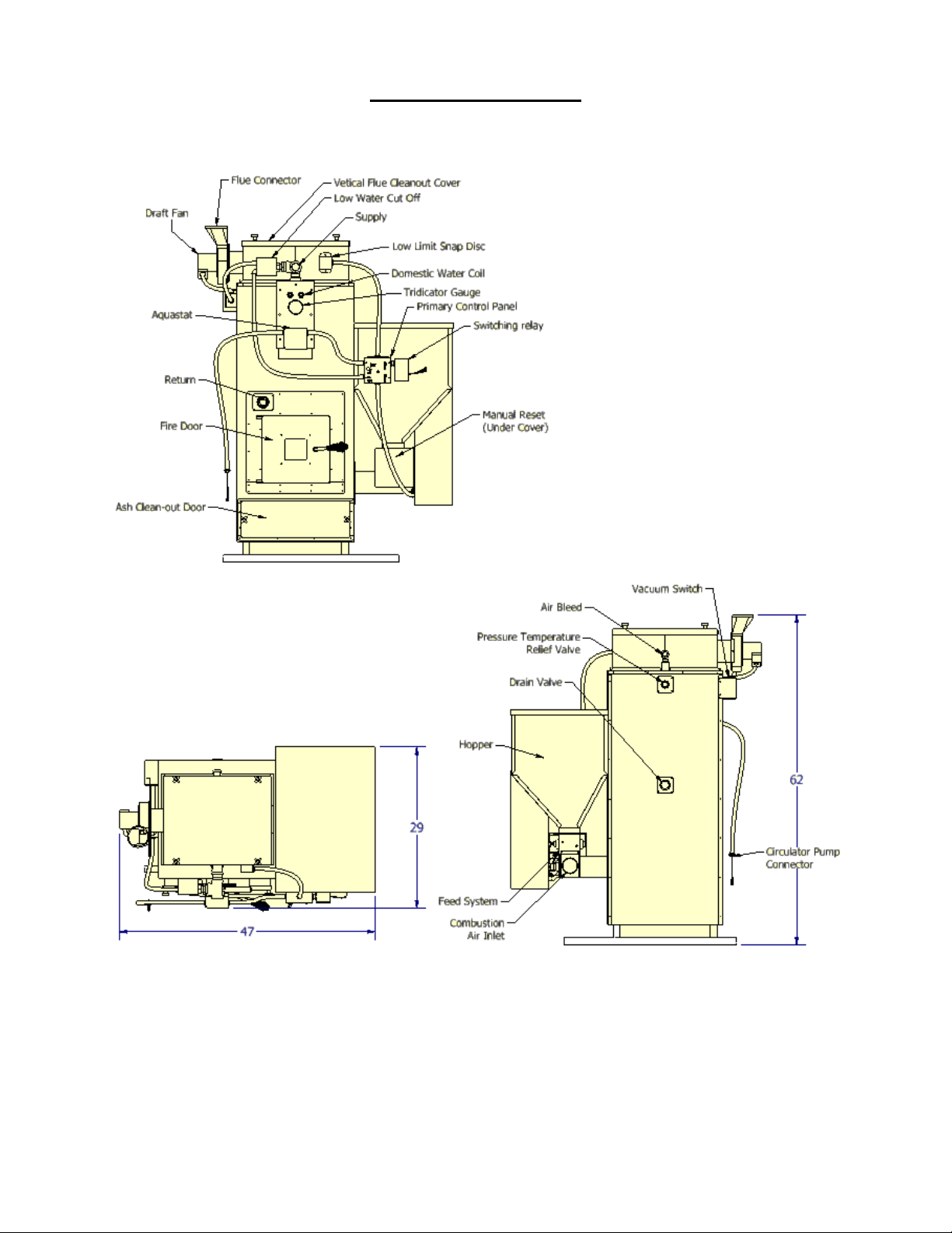
HEIGHT ----------------------------------------- 62”
WIDTH OVERALL ------------------------------- 47”
DEPTH ------------------------------------------ 29”
HOPPER CAPACITY ----------------------------- 160 lbs
WEIGHT ---------------------------------------- 585 lbs
FLUE SIZE -------------------------------------- 4”
BREACH ---------------------------------------- LEFT SIDE
DOMESTIC HOT WATER COIL (GPM) --------- 5 gal
(5 GPM. 40°F to 140°F boiler water temperature at 200°F)
WATER CONTENT (GALLON) ------------------ 16 gal
SUPPLY TAPPING ------------------------------- 1-1/4”
RETURN TAPPING ------------------------------ 1-1/4”
RELIEF VALUE TAPPING ----------------------- 3/4”
Page 4
3
SPECIFICATIONS
Figure 1
Page 5

4
INSTALLATION
GENERAL
The PB150 hot water steel boilers are high quality pellet/corn fired heating units. The
installation of the unit shall be in accordance with the regulations of the authorities
having jurisdiction.
FREIGHT CLAIMS
All units should be inspected for damage upon arrival. Concealed damage claims
should, be filed immediately against the carrier by the consignee. The carrier is
responsible for taking prompt action on all c laims.
SIZING
A complete heat loss calculation of the structure is necessary to choose the proper
size unit to install. The boiler should be sized to within 25% of the actual calculated
heat loss of the structure. Over sizing will result in short cycling and inefficient
operation. The PB150 boilers have large water content allowing for ample domestic
hot water.
Replacement boiler should not be sized from the firing rate of the old boiler. A DOE
sponsored study indicates 65% of the heating units in U.S. homes are substantially
oversized.
BOILER LOCATION
Boiler to be installed on a non-combustible heat resistant surface in a liquid
containment pan attached to a drain in a level position with clearances in accordance
with NFPA 31 Table 4-1 Form IL
STANDARD CLEARANCES
Sides 6” 152mm
Rear 6” 152mm
Chimney Connector 18” 460mm
Reduced clearance installations shall comply with NFPA 31 Table 4-2
Appendix B.
To move the unit, push against the flue box or skids. Pushing or pulling the jacket or
burner will result in damage.
Be sure to level the unit by inserting shims under the base.
AIR FOR COMBUSTION AND VENTILATION
The unit must be installed where provision exists for combustion and ventilation air.
Ordinarily, provisions may be furnished by the following methods:
UTILITY ROOM
In buildings of tight construction, including most modern homes, you should provide
an opening, connecting to a well-ventilated attic, crawl space or directly with the
outdoors. The opening should have a minimum free area of 1 square inch per 1,000
BTU per hour of total input for all appliances in the enclosure and should terminate
below the burner level. Boilers installed in confined areas must have two ventilation
Front 24” 610mm
Page 6

5
openings in the door. Each opening should have a free area of not less than 1 square
inch per 1,000 BTU (140 square inch per US GPH) of the total input for all appliances
in the enclosure. O ne opening located, near top of enclosure and one near th e b ottom.
BASEMENT
Where a boiler is installed in a full basement, infiltration is normally adequate to
provide air for combustion.
In buildings of tight construction where the basement windows are weather stripped,
one opening communicating with a well-ventilated attic or with the outdoors should be
provided. The opening should have a minimum free area of 1 square inch per 1,000
BTU per hour of total input for all appliances in the enclosure.
SPECIAL CONDITIONS
Where a boiler is located in an area where the operation of exhaust fans, kitchen
ventilation systems, clothes dryers, or fireplaces may create conditions of
unsatisfactory combustion or venting, special provisions should be made for additional
air for combustion, as specified by local authority.
TRIM ASSEMBLY
Install the drain valve in the 1-¼” tapping on the backside of the boiler. Install the
safety relief valve in the ¾” tapping on the backside of the boiler. The safety relief
valve should be piped to a place of safe discharge. Install your air bleed connection
into the 90° elbow mounted in the top ¾” tapping behind the smoke collector box.
Install the altitude gauge in the ¼” tapping provided on the front in the coil plate.
PACKAGED BOILER
Controls and burner are installed and pre-wired at the factory. Install Relief Valve as
noted in Trim Assembly.
BOILER PIPING
Minimum sup ply and retur n pipe size of no t less than 1¼” to be used.
The recommended locations of pumps, expansion tanks, etc. are illustrated in Figures
2, 3, & 4. Relief valve discharge and drain valve piping should be piped to a safe place
of discharge. ALL plugs and water connections should be checked for leaks upon
installation and annually.
TANK-LESS WATER HEATING PIPING
The tank-less heater may be connected as shown in Figure 4. A mixing valve (not
supplied) may be used to reduce the water temperature at kitchen or bathroom taps.
When connecting to the domestic water coil a pressure temperature relief valve must
be installed.
High temperature water for a dishwasher may be obtained by piping as shown.
THE NUTS THAT SECURE THE TANKLESS COIL FLANGE SHOULD BE TIGHTENED
BEFORE THE BOILER IS FILLED WITH WATER, AFTER INITIAL FIRING AND EVERY
YEAR DURING ANNUAL MAINTENANC E. DETERIORATION DUE TO CO IL G ASKET LEAKS
SHALL VOID WARRANTY.
Page 7
6
BURNER AND C O NT ROLS
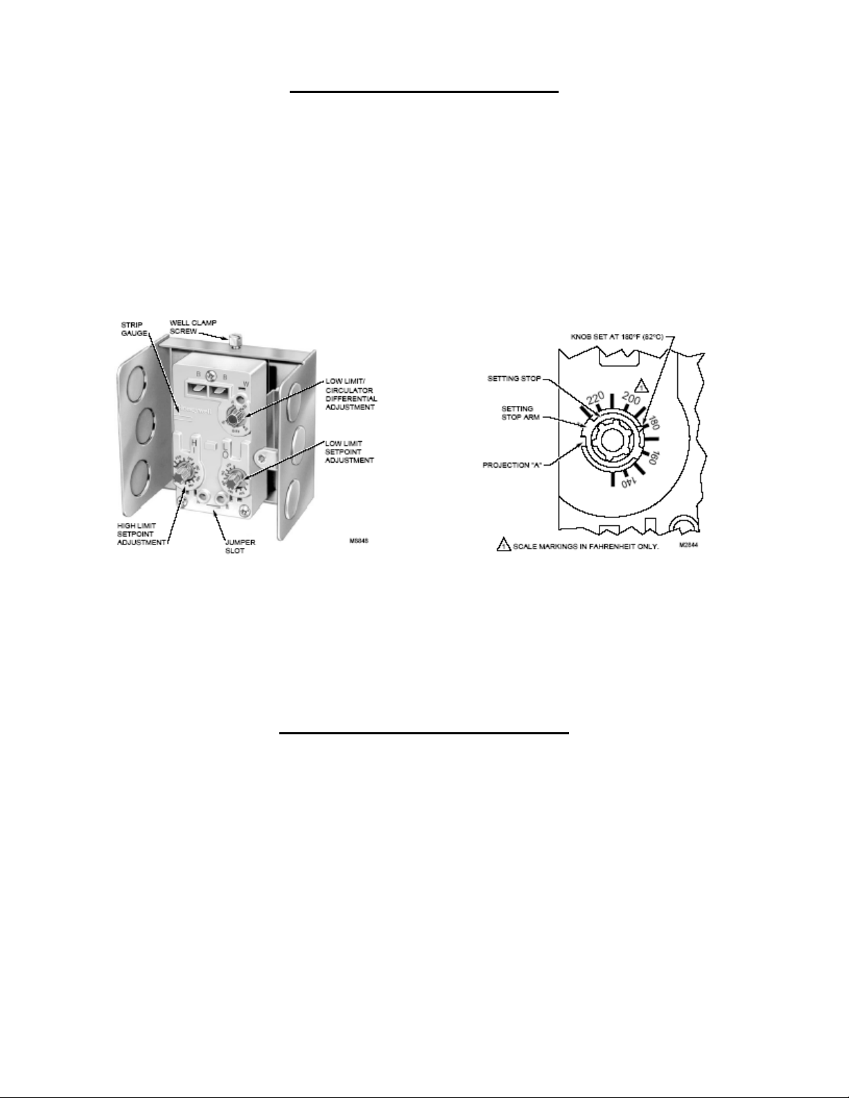
Honeywell L6081A Aquastat Controller
This control is installed on the middle fitting of the domestic coil. These immersion
type controls are used with forced hydronic heating systems, which include domestic
water service. This model provides high limits, low limits for maintaining minimum
boiler water temperature and circulator controls. See the wiring diagram for proper
connections of this unit. The primary control is factory wired to the aquastat
controller. These controls working as a system will prevent the circulator operation if
the water temperature is below a predetermined low level. Likewise, if the water level
reaches a predetermined high limit the burner will automatically shut off.
Low Water Cut-off Switch RB-122
This control is installed in the supply tapping in the top front of the boiler. The RB-122
low water control is specifically designed to provide burner cut-off if there is an unsafe
water loss, which can result from a broken or leaking radiator or pipe, or a cracked
section in the boiler.
SEQUENCE OF OPERATION
Forced Circulation Hot Water System with Tank-less Heater
When the room temperature falls below thermostat setting, thermostat calls for heat
switching the control to full burn mode. When water temperature rises to the preset
temperature setting on the low limit – circulator control the circulator pump is turned
on providing hot water to room zone. At the same time the relay trips and reduces the
burner to pilot mode preventing over temperature. If the circulator pump turns off
because of low water temperature before the room thermostat is satisfied the relay
energizes and switches the burner back to full burn mode to increase the water
temperature. This cycling will continue until the room thermostat is satisfied. When
the room thermostat is satisfied the burner will switch back into pilot mode waiting for
the next heat demand. Because the burner stays in pilot mode between calls for heat,
in extended low demand periods the water temperature may rise enough to turn the
circulator pump on therefore a dump zone should be configured into the system.
Page 8
7
3A 250V
Power In
The On Time controls the amount of time the burner stays
The On Time is subtracted by the Cycle Time Example:
you a complete cycl e time of 16 minutes.
The 0II350S primary control has 6 lead wires. A wiring
auger motor and cup motor. Orange feeds the draft
inducer. 2 yellows go to the wall thermostat.
ON TIME (2MINUTES)
FUSE
RED LIGHT INDICATOR
15 SECOND ON/OFF
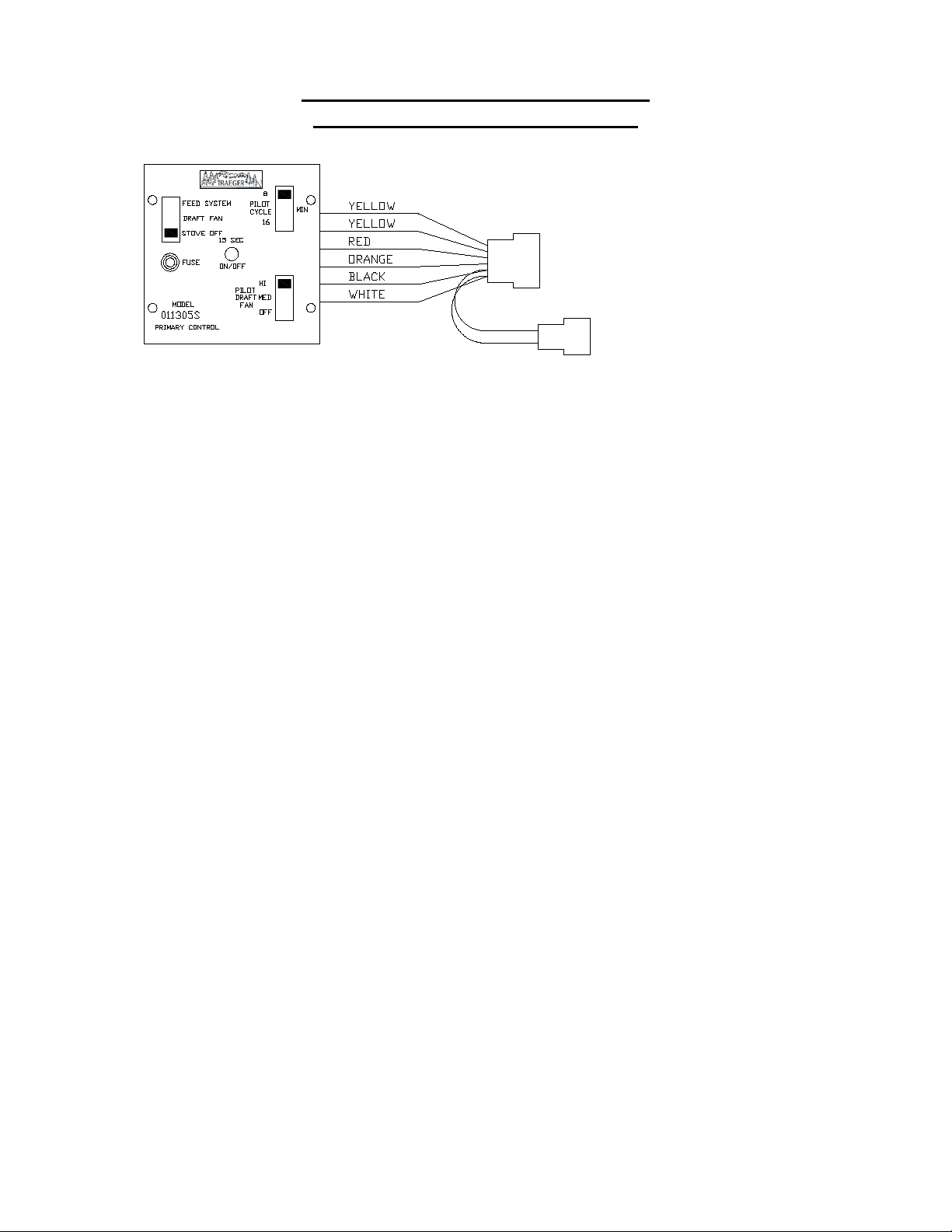
PRIMARY CONTROL 0II350S
SEQUENCE OF OPERATION
The Traeger 0II350S primary
control is a high-tech, state of
the art computer. The control
performs the function of
piloting the system when the
thermostat does not call for
heat. It conserves fuel
consumption.
The computer board is protected by an AGC 3-amp fuse.
There are many manufacturers of this fuse. Fuses are
readily available at your local hardware or auto parts
store.
When the wall thermostat circuit is closed, and calling for
heat, the light indicator will remain dim as long as the
circuit is closed. When the thermostat is open (not calling
for heat) the light will blink from bright to dim every 15
seconds as part of the counting procedure.
active (fuel is fed). It operates in conjunction with the
cycle time and is pre-set in the control at 2
PILOT CYCLE TIME
SWITCH
The PILOT CYCLE time switch controls the total cycle both
on and off, 8 or 16 minutes.
COMBINATION FUNCTION OF
ON TIME AND CYCLE TIME
With the On Time pre-set at 2 minutes and the Cycle T ime
set at 16 minutes, the unit would come on (feed corn) for
2 minutes and not feed corn for 14 minutes. This gives
WIRING
colour code is provided on back of each control. Blac k is
line power. White is neutral. Red is load and feeds the
POWER SWITCH
The POWER switch cuts power to burner but not blower
fan system and to shut the furnace down.
PILOT DRAFT SWITCH
The PILOT DRAFT switch controls the speed of the draft
inducer on pilot or idle mode. Normally set on Medium,
but will vary with differing chimney configurations.
minutes
Page 9

8
FUNCTIONING OF SAFETY AND OPERATING CONTROLS
The safety and operating controls shall function within the limits specified by the
manufacturer for the type of equipment. The following tests shall be performed:
(a) Check the operation of the automatic fuel feeding interrupt device at each
entrance to the floor space within which the fuel-feeding device is installed.
(b) Check that when the low water level control on steam and hot water boilers is
operated to indicate a low water level, the automatic fuel-feed is interrupted.
(c) Check that when the excessive pressure control on steam and hot water boilers is
operated as in an excessive pressure situation, the automatic fuel-feed is
interrupted.
(d) Check that when the excessive water temperature control on hot water boilers is
operated to indicate excessive water temperature, the automatic fuel-feed is
interrupted and, if appropriate, that one or more zone control valves open.
(e) Check that if the temperature exceeds 95°C (200°F) in a furnace supply plenum
on hot air furnaces, the automatic fuel-feed is interrupted.
(f) Check that if there is a failure of the fan providing combustion air, the automatic
fuel-feed is interrupted.
(g) Check that if there is a failure of the combustion air supply control mechanism to
remain fully open, the automatic fuel-feed is interrupted.
(h) Check that when the hot water circulating pump manual disconnect switch, is
opened, the automatic fuel-feed is interrupted.
(i) Check that if there is a shutdown or failure of the mechanical flue-gas exhauster,
the automatic fuel-feed is interrupted.
(j) Check that if there is a failure in the flue gas flow, the automatic fuel-feed is
interrupted, or the combustion air supply is shut off in manually fuel appliances.
(k) Check for the proper operation of the minimum fire maintenance controls and
system or, if applicable, of the automatic ignition system.
(l) Check for the proper operation of the controls used for normal automatic fuel
feeding.
(m) Check the operation of any other controls supplied on the appliance by the
manufacturer, or required by the authority having jurisdiction.
Page 10

9
air inlet to any other appliance.
property.
G
I
H
F
C
B
B
B
B
J
A
B
D
E
L
A
G
M
= Vent Termination = Area where termination is not permitted
= Air Supply Inlet
K
Opens
Opens
VENTING
Vent Termination Requirements:
Table 1: For use w ith Figure 1 for allowable exterior vent termin ation locations.
Letter Minimum Clearances Description
A 2 4 in (61 cm) Above grass, top of plants, or any other combustible mater ials.
B 48 in (122 cm) From beside/below any door or window that may be opened.
C 24 in (61 cm) From above any door or window that may be opened.
D 2 4 in (61 cm) Below any ventilated soffit or roof overhang.
E 12 in (30 cm) Below any unventilated soffit or roof overhang.
F 12 in (30 cm) To outside corner.
G 12 in (30 cm) To inside corner, combustible wall (vertical and horizontal terminations).
H 3 ft (91 cm) within a height of 15 ft (4.5
m) above the meter/regulator
I 6 ft (182 cm) To service regulator vent outlet.
J 3 ft (91 cm) From any forced air intake of other appliance
K 4 8 in ( 122 cm) Clearance to non-mechanical air supply inlet to building, or the co mbus tion
L 7 ft (2.13 m) Clearance above paved sidewalk or paved driveway located on public
M 24 in (61 cm) Clearance above any roofline for vertical terminations.
To each side of center line extended above natural gas or propane
meter/regulator or mechanical vent.
WARNING: Venting termination must not be recessed into a wall or siding.
NOTE: Always consider wind effects upon exhaust emissions when placing exhaust
termination.
NOTE: Do not termi nat e t he vent in any enclosed or semi-enclosed areas such as a
garage, carport, attic, crawlspace, narrow walkway, under a porch or sun deck etc.
NOTE: PL Vent requi r es a minimum of 3 inches (8 cm) clearance to combustibles.
Figure 2
Page 11

10
VENTING
Chimney required for the PB150 is 4” Class “L” (also known as PL
vent). A starting collar must be used to attach the venting system to
the furnace. When connecting into a Class “A” or masonry chimney a
listed 4” liner MUST be used to prevent back drafting of the chimney.
EXISTING CLASS “A” CHIMNEY:
Run 4” Class “PL” connector from the furnace connection to a positive
connection with the class “A” chimney. A LISTED 4” STAINLESS STEEL
LINER MUST BE USED IN CLASS “A” CHIMNEYS. Make sure each
joint is f irmly loc k ed into place. Make sure the attachment of Class “PL”
to the Class “A” chimney is secure with sheet metal screws. Seal all joints
with high temperature silicone. Class “PL” connector should maintain a
pitch on rise from the furnace to the chimney of at least ¼” per foot.
A): “PL” Vent connector 4” B): “PL” Vent elbow 90° adj. 4”
EXISTING MASONRY CHIMNEY: Run 4” Class “PL” connector from
the furnace connection to a positive connection with the masonry
chimney. Make sure each joint is firmly locked in place. Make sure
the penetration of the Class “PL” connector into the masonry chimney
is sound and secured with high temperature cement. Seal all joints with
high temperature silicone. Class “PL” connector should maintain a pitch
on rise from the f u rnace to t h e chimney of at least ¼” p er f oot.
A LISTED 4” STAINLESS STEEL LINER MUST BE USED IN MASONRY
CHIMNEYS. Your new furnace is so efficient; an unlined chimney could
remain cold and cause a downward pressure creating poor burning,
incomplete combustion or back draft.
A.)“PL” Vent connector 4” B.)“PL” Vent elbow 90° adj. 4”
____________________________________________________________________
______
NEW VERTICAL INSTALLATIONS: Install 4” Class “PL” chimney and
accessories according to manufacturers instructions and local codes
(3” clearance to combustibles). Run Class “PL” chimney all the way from
the furnace connection to point of termination. Make sure each joint is
firmly locked in place. Seal all joints with high temperature silicone.
Class “PL” connector should maintain a pitch on rise from the furnace to
the chimney of at least ¼” per foot.
A.) Vertical top 4” D.) Adj. flashing 4”
B.) “PL” Vent pipe 4” E.) Fire stop spacer 4”
C.) Storm Collar 4” F.) “PL” Vent 90° adj. 4” clean out tee
Horizontal runs should be kept as short as possible while maintaining
sufficient draft to operate the appliance properly.
Pinnacle Stove Sales provides no warranty or assumes any
responsibility for smoke damage caused by reverse drafting of any
pellet appliance under power failure conditions.
Page 12

11
VENTING
GENERAL- A PELLET/CORN FIRED UNIT SHALL BE CONNECTED TO A FLUE HAVING
SUFFICIENT DRAFT AT ALL TIMES TO ASSURE PROPER OPERATION.
1. Only a trained experienced serviceman should attempt the installation or
service of any boiler and or venting device. All venting installations must
comply with the recommendations of the venting manufacturer and with all
state and local codes. Only use listed PL type venting with an inside diameter of
4 inches. Warning, used chimney venting must be clean and in good condition.
2. All joints must be securely locked together, caulked with high temperature
silicone and fastened with at least 3 screws. This will prevent leakage and
future disassembly.
3. PL Vent must be supported from the structure by means of metal or other non-
combustible supports; horizontal pipes shall be supported at intervals not
exceeding 3 ft (1 m), exterior vertical pipes shall be supported at intervals not
exceeding 6ft (2 m).
4. DO NOT INSTALL A FLUE DAMPER IN THE EXHAUS T V ENTING SYSTEM
OF THIS UNIT; and DO NOT CONNECT THIS UNIT TO A CHIMNEY FLUE
SERVING ANOTHER APPLIANCE.
BOILER DAMPER CONTROLS
Damper operation
The damper is a plate that helps control the amount of airflow supplied for proper
combustion. With the damper pushed all the way in the airflow is at its minimum. As
the damper is pulled out, more air is allowed to flow.
It will be necessary to monitor the appearance of the flame during the first 4-8 bags
of fuel. If your flam e is sm ok y red/orange with evid en ce of soot at the top of the
flame, you need more combustion air, pull the damper out ¼ inch and re-evaluate the
appearance of the flame. It may be necessary to repeat this process, moving the
damper ¼ inch at a time until proper combustion is attained (the flame should
become yellow and begin to “dance”). Tighten the damper lock down bolt and monitor
flame to maintain proper combustion.
Symptoms of insufficient combustio n air include unburned fuel, lazy smoky
or red/orange flame, excessive ash or soot, excessive build-up on g lass.
Symptom of e xc essive comb ust ion air incl ude fuel burn s t o quickly (smoking
or smouldering pellets), white to yellow flame.
Page 13

12
WARNING ABOUT CHIMNEY FIRES
Failing to maintain your woodstove or fireplace properly can lead to a
chimney fir e . Chimney fire s o c c ur when combustible deposits on the inner
walls of the chimney ignite. These combustible deposits, called "creosote,"
are a natural by-product of wood burning. A fire hazard exists if ¼” of
creosote (o r more) coats t he inner wall s o f t he chimney.
Prevention:
Have a professional chimney sweep clean and inspect your appliance at least once a
year. More frequent cleanings may be required, based on the type of wood burned,
the type of appliance, and the frequency of use. In general, an older, uncertified
woodstove, or any appliance that is used frequently, will require more than one
cleaning per year.
Detection:
that grows louder as the fire’s intensity increases. Clouds of black smoke and sparks
will be seen exiting the top of the chimney; in severe fires, flames can extend several
feet above the chimney.
Action: In case of a chimney fire, follow these steps:
1. Call the fire department immediately.
2. Alert others in the house to evacuate.
3. Close the appliance’s dampers and/or the primary air inlet controls, limiting the
fire’s air supply and reducing its intensity.
4. Open the appliance door just enough to insert the nozzle of a 10 lb. dry
chemical fire extinguisher rated for Class ABC fires. Discharge the entire
content of the extinguisher into the appliance and shut the door.
5. If possible, wet down the roof and other outside combustibles to prevent fires
ignited by shooting sparks and flames.
6. Closely monitor all combustible surfaces near the chimney. During severe
chimney fires, th ese s u r faces can become hot enoug h to ignite.
Chimney fires do not occur in clean, intact, properly installed chimneys.
The first indication of a chimney fire is usually the noise—a roaring sound
After a chimney fire, have the chimney inspected by a professional chimney sweep or
woodstove/fireplace installer; choose a professional who has earned credentials from
the National Chimney Sweep Guild at www.ncsg.org, Chimney Safety Institute at
www.csia.org or the Hearth Education Foundation at www.hearthed.com.
Contact your insurance carrier.
DO NOT USE THE CHIMNEY UNTIL A PROFESSIONAL HAS INSPECTED IT.
The excessive heat produced by a chimney fire can crack chimney walls, damage
chimney liners, and damage some types of factory-built chimneys. If not repaired,
these damages create a greater possibility for any subsequent chimney fire to spread
beyond the confines of t h e flue to the house.
Page 14
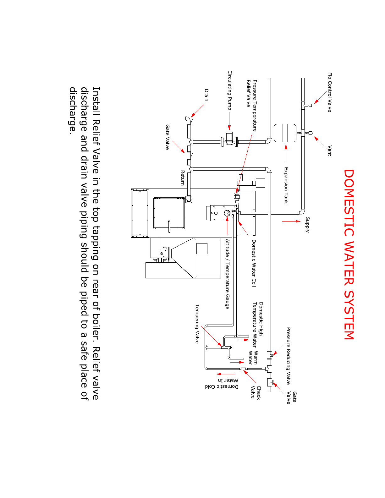
13
Figure 3
Page 15

14
DOMESTIC WATER COIL CON NEC TION
DOMESTIC HOT WATER OUT
DOMESTIC COLD WATER IN
DOMESTIC WATER COIL
PRESSURE & TEMPERATURE
RELIEF VALVE
TEMPERATURE /
ALTITUDE GAUGE
AQUASTAT RELAY
BOILER FRONT VIEW
When installing the domestic water coil connection an ASME certified pressure /
temperature relief valve must be installed. Install pressure temperature relief
valve in the hot water supply side exiting the domestic water coil, see figure 5. Drain
valve piping should be piped to a safe area for discharge. Failure to install pressure
temperature relief value will void boiler warranty.
Pressure Temperature Relief Valve Installation
Figure 4
Page 16
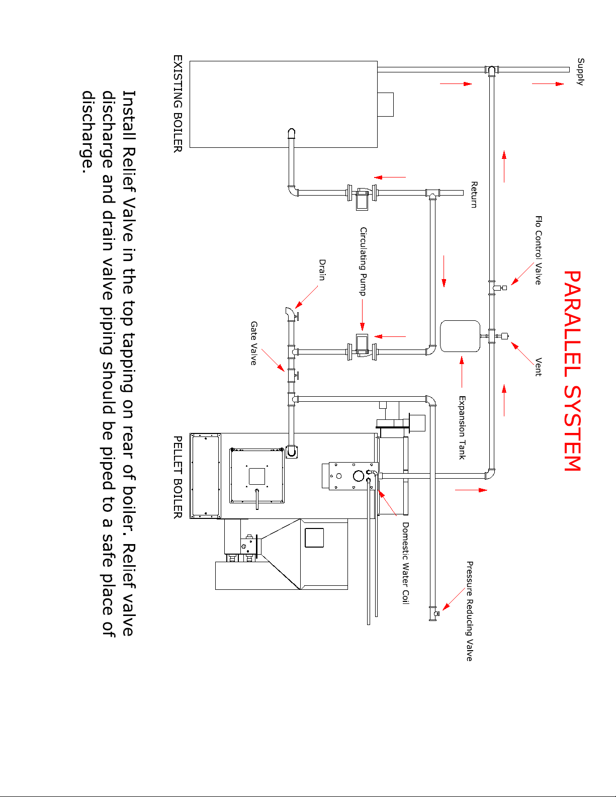
15
Figure 5
Page 17
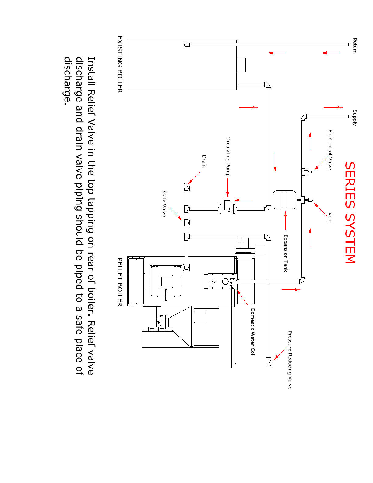
16
Figure 6
Page 18

17
WIRING INFORMATION
All internal electrical wiring is completed at the factory. All external wiring must
conform to the National Electric Code and any local codes. Line voltage leads utilize
wire nut connections.
A surge suppr essor should b e installed to protect cont rol board.
Surge suppressors are available now that mount to your breaker box
providing protection to your whole house.
Refer to the wiring diagrams for all field wiring.
A. Field connections should be protected with a 15-amp fuse.
B. Install the room thermostat on an inside wall away from cold drafts,
windows, or heat from fireplaces, appliances, or sunlight. Set the heat
anticipator at .1 amps. Connect the thermostat leads to the yellow wires on
control board.
C. Install a separate fused disconnect switch near the unit so power can be
shut off for servicing.
D. Shut off service switch when the boiler is not in use for extended periods.
E. Failure to provide surge protection will void control board warranty.
WARRANTY
The limited warranty is not applicable unless these installation instructions are
followed.
HOMEOWNER INFORMATION
A. COMBUSTION AIR SUPPLY
Your burner requires an ample amount of clean combustion air in order, to
completely and efficiently burn its fuel. If an ample supply is not available
erratic operation, noise combustion, and fuel odours in the air may result.
REMEMBER THAT VENTING FANS OR A VENTER DRYER WILL GREATLY
INCREASE THE NEED FOR OU TSI DE AIR.
B. AREA AROUND THE BOILER
The area around the boiler should be kept clean and free or any combustible
materials, particularly oily rags or papers. The boiler should be accessible for
ease of service.
SERVICE INFORMATION
To avoid unnecessary expense and inconvenience, the boiler and burner, should be
inspected at least once a year by a qualified serviceman. If difficulty occurs, the
following should be observed before calling the serviceman:
A. Check to see if the thermostat setting is above room temperature
B. Check to see if the service sw itch is in the on position
DO NOT TAMPER WITH THE UNITS OR CONTROLS
POWER FAILURE
In case of power failure the combustion fan will stop and the fuel feeding motors will
stop feeding fuel to the fire pot. If this happens switch the primary control on/off
switch to DRAFT FAN. Should the power come back while the fire is smouldering the
emissions will be evacuated from the boiler, also this will prevent fuel from being fed
into the fire pot. When power is resumed and the fire is extinguished the boiler can be
safely restarted following the START-UP INSTRUCTIONS.
Page 19

18
Low Limit Snap Disc
Low Water Cutoff
Vacuum Switch
Cup Motor
Auger Motor
Manual Resetable
High Limit Snap Disc
Thermostat
Thermostat
Relay
Aquastat
Circulator Pump
Draft Fan
GND
Pimary Control
L1
L2
N
H
B
C
2
4
1
3
B B
RR
W
Power Requirements:
110 Volts
15 Amps max
Wire through a service switch.
Surge protection required.
RED
RED
WHITE
BLACK
ORANGE
RED
YELLOW
YELLOW
WHITE
BLACK
WHITE
PURPLE
YELLOW
BLACK
BLACK
WHITE
ORANGE
WHITE
WHITE
YELLOW
BLACK
RED
BLUE
WHITE
BLACK
BLUE
BLUE
RED
BLUE
WHITE
BLACK
YELLOW
YELLOW
YELLOW
WHITE
BLACK
ORANGE
BLACK
GREEN
JUMPER
PB150 BOILER WIRING
Figure 7
Page 20

19
BURNING CORN IN THE PB150
1. The PB150 will burn most types of clean-shelled corn. It is not necessary to mix
the corn with wood pellets, although some people have had good success
burning a 50/50 mix. The PB150 boiler is supplied with a plug in the metering
cup. When burning corn leave this plug in to prevent over fuelling the boiler.
2. Typically burning corn requires a bit more combustion air than wood pellets.
The shutter on the draft inducer should be set at no less than 50% open, the
cycle time at 8 minutes, and the pilot draft switch on the primary control
medium.
3. The moisture content of the corn should be 15% or less, and care should be
taken to ensure that there are no foreign objects in the corn (i.e. sticks, stalks,
cob pieces) which will jam the feed system.
4. We recommend starting a corn fire with wood pellets as corn has a dense shell
that can be difficult to start. Note that corn has more BTU’s than wood pellets,
about 10,000 BTU’s per pound. Use gel starter to light unit.
WARNING
DO NOT USE CHEMICALS OR FLUIDS TO START THE FIRE.
DO NOT BURN GARBAGE, GASOLINE, NAPHTHA, ENGINE OIL OR OTHER
INAPPROPRIATE MATERIALS.
5. When burning corn, the primary combustion takes place on a fluidized bed at
the bottom of the fire pot. That’s why the corn pot has a slide bottom. The slide
bottom corn pot will need to be cleaned about once every 300 – 400 pounds of
corn (approx. 4 – 6 days). A white calcium-like deposit will be present in the
bottom of the fire pot. This deposit needs to b e r emoved. We recommend
shutting off the unit by turning the on/off switch on the primary control to the
off position, letting the unit cool, and then pull the slide bottom completely out.
You may have to tap the top of the deposit to make it fall into the ash pan. We
would recom m end purchasing an extra pot to make cleaning easier. Let
the pot cool completely to the touch and place into a bucket of water to
dissolve the clinker. DO NOT PLACE HOT POT IN WATER. You can also let
the pot sit in the air for 2-3 days then dump the residue out. DO NOT USE ANY
OBJECT TO POUND OUT THE CLINKER. THIS WILL DAMAGE YOUR POT. THERE
IS NO WARRANTY ON BURN POTS.
6. Place 1” of course oyster shell in the bottom of the pot before using. Under
heavy usage it may be necessary to remove the clinker daily. A bit of oyster
shell will be removed with the clinker. When all oyster shell has been removed,
remove pot for a thorough cleaning and replace with new pot, or clean and
replace oyster shell and pot.
Page 21

20
START UP INSTRUCTION S
1. Make sure service switch to boiler is off.
2. Make sure boiler has been filled with water until entire system has been purged
and desired pressure is obtained.
3. Check all fittings for leaks.
4. The PB150 boiler is supplied with a plug in the metering cup. If burning wood
pellet only, this plug can be removed to increase firing rate.
5. Add fuel to the hopper. If burning corn add oyster shell to the pot.
6. Set shutter on draft fan at 50% (1/2 way open).
7. On the aqua stat set the high limit control on the left side at 200° F., low limit
control on the right side at 160° F. and the differential setting at 130° F. This is
the factory-preset level.
8. Set primary control (OII350S) cycle time switch at 8 minutes and pilot draft
switch at Medium. Turn on service switch.
9. Place two (4) cups of pellets in the bottom of the fire pot. Apply a non-volatile
lighting material on top of pellets and light with a match.
WARNING
DO NOT USE CHEMICALS OR FLUIDS TO START THE FIRE.
DO NOT BURN GARBAGE, GASOLINE, NAPHTHA, ENGINE OIL OR OTHER
INAPPROPRIATE MATERIALS.
10.Close door and let fire establish. Set on/off switch on primary control to Feed
System
11.Combustion fan should come on to high speed. The fire in the pot will increase.
When the safety disc on the smoke collector box reaches 49°C (120 ° F)
temperature, it will close, and then the cup and auger motor will start adding
more fuel to the fire pot. The unit will run until it reaches 160°F at which time
the burner will cycle into pilot mode and the circulation pump will come on to
supply hot water throughout the system.
Page 22

21
FUEL QUALITY
Pellet quality is very important, please read the following:
Your PB150 boiler has been designed to burn wood pellet or shelled corn. Do
not use any o t her type of fuel, as this wil l void any warranties stated in this
manual.
The performance of your boiler is greatly affected by the type and quality of
wood pellets being burned. As the heat output of various quality wood pellets
differs, so will the performance and heat output of the pellet stove.
To prevent creosote formation a small intense fire is preferable to a large
smouldering fire.
CAUTION: It is important to select and use only pellets that are dry and free of dirt
or any impurities such as high salt content. Dirty fuel will adversely affect the
operation and performance of the unit and will void the warranty. The Pellet Fuel
Industries (P.F.I.) has established standards for wood pellet manufacturers. We
recommend the use of pellets that meet or exceed these standards. Ask your dealer
for a recommended pellet type.
P.F.I. PELLET STANDARDS:
Fines (fine particles)......1% maximum through a 1/8” screen
Bulk Density..................40 pound per cubic foot minimum
Size..............................1⁄4” to 5/16” diameter 1⁄2 – 11⁄2” long maximum
Ash Content..................1% maximum (Premium grade)
.................3% maximum (Standard grade)
Moisture Content...........8% maximum
Heat Content.................approximately 8200 Btu per pound minimum
ASH: The ash content of the fuel and operation of your boiler will directly determine
the frequency of cleaning. The use of high ash fuels may result in the boiler needing
to be cleaned daily. A low ash fuel may allow longer intervals between cleaning.
CLINKERING: Clinkers are silica (sand) or other impurities in the fuel that will form a
hard mass during the burning process. This hard mass will block the airflow through
the Burn Pot and affect the performance of the boiler. Any fuel, even approved types,
may tend to clinker. Check the Burn-Pot daily to ensure that the holes are not blocked
with clinkers. If they become blocked, remove the burn-pot (when the unit is cold)
and clean/scrape the clinkers out. Clean the holes with a small pointed object if
required. Refer to the Maintenance section.
PELLET FEED RATES : Due to different fuel densities and sizes, pellet feed rates may
vary. This may require an adjustment to the slider damper setting.
Pinnacle Stove Sales has no control over the quality of wood pellets or shelled corn
that you use, we assume no liability for your choice in wood pellet or shelled corn fuel.
Store wood pellets or shelled corn at least 36 inches (1 m) away from the
boiler. Do not store fuel within the appliance installation clearances or
within space required for fue lling, ash re moval, and ot her routine
maintena nc e o perations.
Page 23

22
MAINTENANCE
UNIT MUST BE CLEANED AFTER APROXIMATELY 2 TONS OF FUEL TO
ENSURE GOOD EFFICIENCY. MONITOR YOUR BOILER DAILY UNTIL
EXPERIENCE SHOW HOW OFTE N CLEANING IS NECESSARY.
1. Ensure fire is out and boiler is sufficiently cooled to allow proper cleaning.
2. Switch primary control feed system switch to off. Turn off service switch.
3. Open the fire door and remove the slide bottom on the fire pot. Close the fire door.
4. Remov e t op c ov er b y first taking off the 4 phenolic knobs and washers found on top
corner of the cover b ox .
5. Remove the tube baffles by lifting them straight up. There are 14 of them.
6. Run a 3” diameter brush down thru the 3” diameter tubes. Be sure. Push brush all the
way through the tube.
7. Use an approved Ash Vacuum (not your house vacuum) to clean the top of the heat
exchanger.
8. Re-assemble the top of th e b oi ler
9. On a non-combustible surface, well away from combustible materials have ready a
fireproof container with a tight fitting lid, to receive ash. Open the fire door. Remove
and thoroughly clean fire pot. Remove the ash pan; carefully dump ashes into the
fireproof container. Pending final disposal by burial in soil or otherwise locally
dispersed they should be retained in the ash container until thoroughly cooled. Do not
use the ash container to store other waste. Take care not to scrape the sides of the
fire chamber. They are lined with high temperature ceramic firebrick insulation.
10. Inspect and clean chimney of soot, fly ash and possible creosote build up.
11. Replace fire pot
12. Replace fire pot slide.
13. Inspect fire door, ash door and smoke chamber lid gaskets to ensure they are in good
condition to maintain proper seal, preventing leakage.
14. Secur ely close all doors.
15. Restart the boiler as per START-UP INSTRUCTIONS.
TOP VIEW
FIGURE 8
Page 24

23
ALTERNATE PIPING AND WIRING CONNECTIO N
Not all existing systems may be 100% compatible with our PB150 boiler so an
alternate method of connections can be used. These installation options should be
discussed with your hydronic installation specialist to insure proper operation.
Primary and secondary loops
A primary loop of reasonable size of at least 1-¼” pipe from the supply to the return
can be installed. The circulator pump can be wired into the R terminal on the aquastat
allowing for constant operation. Zones are now connected to draw from the primary
loop.
Thermostat Control
The yellow wires that are normally connected to a thermostat can be wired together
bypassing the thermostat. The aquastat will now control water temperature based on
the low limit settings. When the water reaches the low limit temperature the aquastat
will shut down the burner to pilot mode until the water temperature drops below the
low limit setting minus the differential setting. If the low limit setting is 170° F and
the differential is 25° F, this means the burner will fire at the high rate until the water
temperature reaches 170° F and then put the burner into pilot mode until the water
temperature drops to 145° F.
Dump Zones
Be sure to incorporate a dump zone into the system. The dump zone can be controlled
by using a strap on aquastat connected to the supply piping above the boiler.
Lockout Control
When connecting in series or parallel with an existing system, an interrupt to the call
for heat may be needed to prevent both boilers from firing. A normally closed 120° F
snap switch can be installed on the smoke box of the PB150 boiler and wired into the
thermostat circuit of the existing boiler preventing the existing boiler from firing while
the PB150 boiler is in operation. Be sure that when the PB150 boiler is not being used
to shut off its power via the service switch.
Page 25

24
PINNACLE STOVE SALES WARRANTY
NON TRANSFERABLE
MODEL: _PB150 ___ SERIAL NUMBER: _________________
DATE PURCHASED: __________ FROM: __________________ ___
Complete Unit Warranty
The manufacturer provides a warranty on all steel parts (except burn pot) and electrical
components against defects in material or workmanship under normal use and maintenance for
a period of one (1) year from the installation date. There is expressly no warranty on the
following components: burn pots, firebrick, fibreglass rope gasket, paint, or gaskets. This
warranty covers defects in materials and workmanship in covered components, provided the
product has been installed and operated str ictly in accordance with Manufacturer’s printed
instructions. This warranty does not cover damage or breakage caused by improper handling,
misuse or unauthor ized modification. Without limiting the foregoing, t he use of fuels other t han
pelletized wood or fuel corn will void all warranties and liabilities. Commercial applications
are warranted for a period of three (3) months on s teel parts and electrical components.
Pinnacle Stoves Sales Inc. reserves the r ight to determine commercial applications. All claims
under this warranty must be made in writing to the Manufacturer at Pinnacle Stove Sales Inc,
1089 Hwy 97N, Quesnel, BC V2J 2Y3 and should include the following.
1.Name, address, and telephone number of servicing dealer.
2.Name, address, and telephone number of purchaser
3.Date of purchase
4.Model & seria l number of unit.
5.Nature of the defect, malfunction and/or compla int. Local representatives are to inspect
parts and or unit. If the inspection indicates that the failure was due to defective material or
workmanship in covered components and that the other terms and conditions of this warranty
have been complied with t he manufacturer’s sole d u t y and liability unde r t h is warranty shall be
limited to the manufacturer’s replacement or repair, at manufacturer’s option, of the defective
unit or part. The purchaser shall assume all costs of shipping to and from the manufacturer.
Removal, reinstallation and diagnostic costs are not covered under this warranty.
Extended Parts Warranty
In addition to the above complete unit warranty, the following applies:
Five (5) year extended warranty, pro-rated, on boiler vessel, residential use.
One (1) year extended warranty, pro-rated, on boiler vessel, commercial use
NEITHER THE MANUFACTURER, NOR THE SUPPLIER TO THE PURCHASER,
ACCEPTS RESPONSIBILITY, LEGAL OR OTHERWISE, FOR IN DICENTAL OR
CONSEQUENTIAL DAMAGE TO PROPERTY OR PERSONS RESUL TING FROM THE US E OF
THIS PRODUCT, ANY WARRANTY IMPLIED BY LAW, INCLUDING BUT NOT LIMITED TO
IMPLIED WARRANTIES OF MERCHANTABILITY OR FITNESS, SHALL BE LIMITED TO
ONE YEAR FROM THE DATE OF ORIGINAL PURCHASE. WHETHER A CLAIM IS MADE
AGAINST THE MANUFACTURER BASED ON A BREACH OF THIS WARRANTY OR ANY
OTHER TYPE OF WARRANTY, EXPRESSED OR IMPLIED BY LAW, MANUFACTURER
SHALL IN NO EVENT BE LIABLE FOR ANY SPECIAL, INDIRECT, CONSEQUENTIAL OR
OTHER DAMAGES OF ANY NATURE WHATSOEVER IN EXCESS OF THE ORIGINAL
PURCHASE PRICE OF THIS PRODUCT. ALL WARRANTIES BY MANUFACTURER ARE SET
FORTH HEREIN AND NO CLAIM SHALL BE MADE AGAINST MANUFACTURER ON ANY
ORAL WARRANTY OR REPRESENTATION.
Some states/provinces may not allow the exclusion or limitation of consequential damages, or
limitations of implied warranties, so the limitations or exclusions set forth in this warra nty may
not apply to you. This warr anty gives you specific legal rights and you may also have other
rights, which vary from state to state, province to province.
Page 26

25
TROUBLE SHOOTING GUIDE
Tools Essential for Trouble Shooting
1. Furnace Installation and Operation manual
2. Circuit Tester / Volt Meter
3. Molex pin Extractor
4. Volt Meter
STEP #1
ATTENTION: Before attempting any trouble shooting:
1. Check your wiring to control box to insure proper polarity and grounding.
2. Check flue for any blockage.
3. Take time to clean burn pot and heat exchangers.
4. If you have replaced the fan limit control, make sure the brass connector in
the middle has been r emoved or snipped
STEP #2
CONFIRM POWER TO CONTROL BOARD
Turn Main power switch from the “Stove Off” position to the “Draft Fan” position. If
the red indicator light comes on, there is power to the control board. If the light does
not come on check the following:
A. Power Source (See Step # 1)
B. Fuse
C. Burner Manual Reset – If the fuse is not blown and the reset button has not
popped out, inspect the Molex connection. Finally, u si n g a v ol t meter, check for
power at the power switch. If the meter indicates 115v and the light still doesn’t
come on, replace the control board.
STEP 3#
CONFIRM DRAFT FAN OPERATION
Be sure the main power switch is in the “Draft Fan” position. This will cause the draft
fan to operate at full power (115v). The draft fan will operate at 70 – 75v when pilot
draft switch is set at high. It will receive 60 – 65v in the medium position and zero
volts in the off position when furnace is not feeding fuel. You should be able to hear
the draft fan come to full speed. You can check movement of air by placing you hand
over the fire pot. If movement of air is not obvious, make sure that the shutter is
open.
STEP #4
INSPECT FUEL METERING CUP FOR BLOCKAGE
To inspect the metering cup, first you will need to empty the hopper. Reach down
through the hopper and rock the cup back and forth. The cup should mover ¼ of an
inch. If it does not move, something is jamming it. Sometimes the obstruction can be
removed by rotating the blade on the cup motor counter clockwise. If this doesn’t
work you will have to remove the cup motor and cup to remove the blockage.
STEP #5
.
Page 27

26
CONFIRM CUP AND AUGER MOTOR OPERATION
Place a jumper wire between the leads to the safety disc located on the exhaust
flange. Set the main power switch to “feed system”. Both the cup and auger motor
should start now. If the motors run but the fuel metering cup and/or auger do not
turn, check the cast iron couplers to make certain that the set screw is tight or that a
coupler has not sna pped off. NOTE: Anytime you are checking the motors, you should
verify the speed at which motors are turning. This can be accomplished by timing the
revolution of th e cou pler. Using the setscrew as a reference the bottom motor (Auger)
will make one revolution in 10 seconds. The top motor (cup) will make approximately
one revolution every 45 seconds. Remove jumper wire and plug wire leads back to
safety disc.
STEP #6
RELIGHT THE BOILER
Use normal start up procedure to start the boiler.
INSTALLATION/A DJUSTMENT RELATED PROBLEMS
PROBLEM: Incomplete combustion, unburned fuel.
SOLUTION: 1. Adjust air shutter to a more open position.
2. Make sure of correct chimney, is chimney drafting?
Is the chimney direct vented? Is it a tight basement?
Outside air may be needed. What is fuel moisture?
PROBLEM: Burns fuel too quickly and may have difficulty holding
a fire on pilot.
SOLUTION: Adjust air shutter to a more closed position. If that doesn’t
solve the problem, check for an over drafting chimney by
using a draft gauge. To solve over drafting use the following
procedures:
Mas on ry C hi mn e y: Cover top with a plate and mount a
4” cap. If that doesn’t slow it down, use a barometric
damper.
Pellet Vent: Install a barometric damper.
PROBLEM: Smoking
SOLUTION: Make sure that the chimney is not direct vented on a windy
side of the house. Also check gaskets to insure proper sealing.
Adjust damper opening, might be too far closed.
Is heat exchanger clean? Is chimney clean?
PROBLEM: Auger squeaks
SOLUTION: Adjust pillow block bearing by loosening screws on each side.
Page 28

27
Let auger run for one minute. Tighten screws. Auger should
realign itself. Possible build up of carbon on end of auger where it
enters burn pot.
PROBLEM: Decrease in heat output
SOLUTION: Thoroughly clean heat exchanger. Did you start using
different fuel? Shutter on draft fan moved?
OPERATOR RELATED PROBLEMS
PROBLEM: Feed system does not l o c k in.
SOLUTION: Repeat start up using more fuel.
PROBLEM: Boiler will not start up after power outage.
SOLUTION: Check manual reset on feed system.
PROBLEM: Boiler will not feed fuel.
SOLUTION: Check for blockage in metering cup.
Is there fuel in the hopper?
FUEL RELATED PROBLEMS
Symptoms of Poor Fuel:
1. Unburned pellets
2. Fire pot overflows as a result of high moisture content.
3. Lack of heat.
4. Excessive ash build-up.
5. Incorrect size.
Page 29

28
PARTS LIST
Figure 10
1. Hopper connector flange F000221P 8. Cup motor F000101P
2. Pillow block ball bearing F000505P 9. Manual reset F000105P
3. Cutting blades (2) ea. F000513P-2 10. Auger motor F000102P
4. Fuel metering cup F130512P 11. Auger/shaft assembly F150293P
5. ½” lovejoy coupling F000507P 12. Multi fuel burn pot F150999S
6. Spider F000505P
7. ½” lovejoy coupling F000507P
Page 30

29
NOTES
 Loading...