

Page 1

ELECTRICAL INSTALLATION
Electrical Interface
The Optiport E-2 is uses a standard RJ45 8-W ay connector as its
electrical interface, which provides a simple solution for the use r to
setup their system using a standard RJ45 8-Way data cable. The
signal layout of the connector is as follows :
Cable Requirements
Standard 8-way data cables with plugs are available from Invertek
Drives Ltd on request.
If the data cable is made up on site, ensure that the connection pin
out is correct : Pin 1 to Pin 1, Pin 8 to Pin 8 etc.
CAUTION
Incorrect cable connection may damage the dri ve. Extra care should
be taken when using third party cable.
System Setup
The Optidrive E-2 provides the +24V power supply to the Optiport E-2
via RJ45 connection. Once the physical connection has been se tup,
the system is ready to operate. See picture blow:
MECHANICAL INSTALLATION
DIMENSIONS
THROUGH PANEL MOUNT
The panel on to which the Optiport E-2 is to be mounted should be cut
out in accordance with the diagram below.
SAFETY
Optiport E-2 is designed to be used in conjunction with the Optidrive E2 variable speed drive and is intended for professional incorporati on
into complete equipment or systems. The Optiport E-2 can be used t o
control the operation of the Optidrive E-2 range. The drive must be
installed correctly to prevent a safety hazard. The Optidrive E-2 uses
high voltages and currents, carries a high level of stored electrical
energy, and is used to control mechanical plant that may cause injury.
Close attention is required to system design and electrical inst allation to
avoid hazards in either normal operation or in the e vent of equipment
malfunction.
System design, installation, commissioning and maintenance must be
carried out only by personnel who have the necessary training and
experience. They must read carefully this safety information and the
instructions in this and the Optidrive E-2 User Guide and follow all
information regarding transport, storage, installation and use, including
the specified environmental limitations.
Please read the IMPORTANT SAFETY INFORMATION below, and
all Warning and Caution boxes elsewhere.
SAFETY NOTICES
WARNING is given where there is a hazard that c ould lead to injury or
death of personnel.
CAUTION is given where there is a hazard that could lead to damage
to equipment.
Dr David Jones, R&D Director
DECLARATION
All rights reserved. No part of this User Guide may be r eproduced or
transmitted in any form or by any means, electri cal or mechanical
including photocopying, recording or by any info rmation storage or
retrieval system without permission in writing from the publisher.
Copyright Invertek Drives Ltd © 2007
The manufacturer accepts no liability for any consequences resulti ng
from inappropriate, negligent or incorrect installati on, or adjustment of
the optional operating parameters of the drive or from mismatching of
the drive to the motor.
The contents of this User Guide are believed to be correct at the time
of printing. In the interests of a commitment to a policy of continuous
improvement, the manufacturer reserves the right to change the
specification of the product or its performance or the contents of the
User Guide without notice.
WARRANTY
All Invertek Drives Ltd (IDL) products carry a 2-year warranty, valid
from the date of manufacture. This date is clearly visible on the rating
label.
Complete Warranty Terms and Conditions are available upon request
to your IDL Authorised Distributor.
OPTIPORT E-2
Remote Keypad Option Module
User Guide
Installation and Operating Instructions
IMPORTANT SAFETY INFORMATION
Safety of machinery, and safety-critical applicatio n s
The level of integrity offered by the Optiport E-2 / Optidriv e E-2 control
functions – for example stop/start, forward/reverse and maximum
speed, is not sufficient for use in safety-critical applications withou t
independent means of protection. All applications where malfuncti on
could cause injury or loss of life must be subject to a risk assessm ent
and further protection provided where needed.
Within the European Union, all machinery in whi ch this product is used
must comply with Directive 89/392/EEC, Safety of Machinery. In
particular, the electrical equipment should comply with EN60204-1.
CONFORMITY WITH STANDARDS FOR OPTIDRIVE
• CE-marked for Low Voltage Directive.
• EN61000-4 EMC Generic Emissions Standard, Indu strial Level.
• EN61000-2 EMC Generic Immunity Standard, Industri al Level.
• Enclosure ingress protection, EN60529, NEMA 250.
• Flammability rating according to UL 94.
GENERAL SPECIFICATION
Signal Interface: Standard 6-way RJ45 connector
Supply Input: 10V … 36V DC, 30mA
RS485 signal: industry standard 2-wire +5V differential
Environmental: Operational 0 … 50 °C
Storage -40 °C … 60 °C
Relative Humidity < 95% (non condensing)
Protection rating: IP54
Max cable length: 20m (unscreened, total length)
100m (screened, twisted pair, total length)
WARNING
• When installing the Optiport E-2, all Optidrives should be
disconnected and ISOLATED before attempting any work. High
voltages are present at the terminals and within t he drive for up to 10
minutes after disconnection of the electrical sup ply. The Optidrives
should be installed by qualified electrical persons and in accordance
with local and national regulations and codes of practice.
• Refer to the Optidrive E-2 manual for further details.
CAUTION
• Carefully inspect the Optiport before installation to ensure it is
undamaged.
• Store the Optiport in its box until required. Storage should be clean
and dry. Temperature range -40
o
C to +60oC.
• Install the Optiport on a flat, flame-resistant vibration-free su rface.
• Flammable material should not be placed close to the Optiport.
81
66
55
23
3
Unit: mm
65
70
55
Panel
Cut Out
Unit: mm
8-way ribbon cable with leader
RJ45 Interface
Electromagnetic Compatibility (EMC)
Optidrive is designed to high standards of EMC. EMC data is provided
in a separate EMC Data Sheet, available on request. Under extreme
conditions, the product might cause or suffer disturbance due to
electromagnetic interaction with other equipment. It is the
responsibility of the installer to ensure that the equipment or system
into which the product is incorporated complies with the EMC
legislation of the country of use. Within the Eur opean Union,
equipment into which this product is incorporated must comply with
89/336/EEC, Electromagnetic Compatibility.
When installed as recommended in this User Guide, the radiate d
emissions levels of all Optidrives are less than those defined in th e
Generic radiated emissions standard EN61000-6-4. Th e conducted
emission levels are less than those defined in th e Generic radiated
emissions standard EN61000-6-4 (class A) for the specified motor
cable lengths.
RJ45 Interface Signal Layout
NC
NC
0V
RS485 - / Optibus
RS485 + / Optibus
+24V
NC
NC
1
1
Page 2
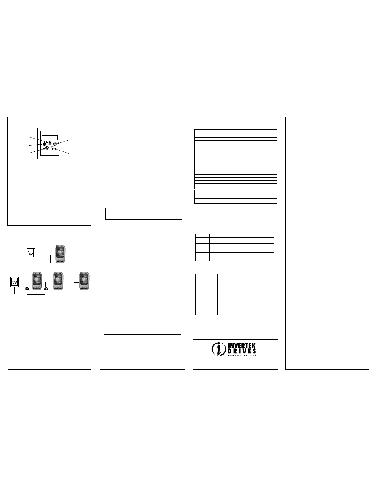
SYSTEM SETUP
Depending on the requirement of the application, Optiport E-2 can be
used in the following different ways:
• One Optiport E-2 with one drive
• One Optiport E-2 with multiple drives
Note: The splitter is available from Invertek Drives Ltd on request.
REAL TIME OPERATION
Once the communication has been setup between the drive and
Optiport E-2, the user can control the Optidrive E-2 by using the
control buttons on the front panel of the Opti port.
To monitor or change a parameter value
• Press and hold the NAVIGATE key for more than 1s when the
drive is displaying “StoP”. The display changes to P-01,
indicating parameter 01 in parameter group 1.
• Press and release the NAVIGATE key to display the value of this
parameter.
• Change to the required value using the UP and DOWN keys.
• Press and release the NAVIGATE key once more to store the
change.
• Press and hold the NAVIGATE key for more than 1s to return to
real-time mode. The display shows “StoP” if the drive is stopped
or the real-time information (e.g. speed, current or power) if the
drive is running.
USER INTERFACE
NAVIGATE:
Used to display real-time information, to access and e xit parameter
edit mode and to store parameter changes
UP:
Used to increase speed in real-time mode or to increase parameter
values in parameter edit mode
DOWN:
Used to decrease speed in real-time mode or to decr ease parameter
values in parameter edit mode
RESET / STOP:
When drive is in trip mode, this button is used to reset a tripped drive.
In normal application, when in Keypad mode, thi s button is used to
stop a running drive.
START:
When in keypad mode, the button is used to start a stopped drive or
to reverse the direction of rotation if bi-directional keypad mode is
enabled (See drive user guide for more information).
NOTES
EASY STARTUP
To setup the communication address
By default, the Optiport E-2 will try to communicate with the drive t hat
has address 1 in the network after powering up for the first time.
The Optiport E-2 will display “SCAN..” after power up, which indicates
that the Optiport E-2 is searching the drive with the correct drive
address in the network. Once the drive has been found, the message
“Load..” will be displayed on the Optiport display window, which
indicates that the Optiport is reading the configur ation information from
the drive. Usually it will take 1~2 seconds for the Optiport to read this
information. After the data has been loaded, Optiport E- 2 will display
the drive real time status.
If the Optiport E-2 doesn’t find the drive in the network, i.e. there is only
one drive in the network and its address is not equal to 1, the Opti port
E-2 communication address will be displayed on the monitor window as
“Adr-01”. The user can then adju st the address from 1 to 63 by using
the UP or DOWN buttons on the Optiport E-2.
Once the address has been changed to a value to match that of the
drive, the STOP button must be pressed t o enable the Optiport E-2 to
search for the drive again.
Once the communication between Optiport and drive has been set up,
user can change the Optiport address to set up communication wit h
another drive in the same drive network at anytime.
Pressing the STOP and DOWN buttons together results in the message
“Adr-XX”, where “XX” represents the present address. Using the UP or
DOWN button to select the desired drive address. After selecting the
new address, pressing STOP and DOWN button together again will
result in Optiport E-2 establishing communications with the drive that
has this address.
Locking access to the parameters
• To prevent un authorised access to the parameters via the Optiport,
set P-38 = 1. Once this parameter has been set, access to
parameters via the Optiport E-2 will be prevented.
• The Operati onal information (speed, current, power etc) can be still
accessed as normal and the drive can still be controlle d from the
keypad.
• To unlock par ameter access, change P2-38 back to 0 via the drive
keypad directly.
Presetting target speed in keypad mode
Set P-12 = 1 or 2 to enable the keypad control, ensu ring that P-31 = 1
or 3 to enable the drive to start from the preset speed.
Whilst the drive is stopped, press the STOP key. The value of the
digital potentiometer will be displayed, indicating ta rget speed. Use the
UP and DOWN keys to select the required target speed.
Press the STOP key to return to t he real time display showing “StoP”,
or the START key to start the drive ramping up to the t arget speed.
To vary the speed in real time in keypad control mode
Press the START key. The drive will ramp up to the preset speed set in
the digital potentiometer (assuming P-31 = 1).
Press UP to increase speed.
The drive will run forward, increasing speed until the UP button is
released. The maximum speed is the speed set in P-01.
Press DOWN to decrease speed.
The drive will decrease speed until the STOP button is released. The
minimum speed is the speed set in P-02.
Pressing the STOP key to stop the drive (suppose P-31 = 1).
The drive will decelerate to stop at the selected decel eration ramp.
The display will finally show “StoP” at which point the drive is disabled.
Pressing the START key once more results in the drive running back
up to the speed at which it was previously running (digital potentiometer
value). (assuming P-31 = 1)
To reverse direction of rotation with P1-12 = 2
Press the START key. The drive ramps up to the preset speed as set in
the digital potentiometer (assuming P-31 = 1).
Press UP or DOWN to increase or decrease the speed.
Press the START key again. The motor will reverse its direction of
rotation.
Press the STOP key to decelerate the motor to standstill.
Whenever the drive is started, it will start with a positive speed unle ss
the direction is negated by the digital inputs on the user terminals
DRIVE TRIP CODE
Fault Code What has happened
P-deF Default parameters loaded
O-I
Over current on drive output.
Excess load on the motor.
Over temperature on the heatsink
I.t-trP
Drive has tripped on overload after delivering
>100% of value in P-08 for a period of time.
OI-b Brake channel over current
OL-br Brake resistor overload
PS-Trp Internal power stage fault
O-Uolt Over voltage on DC bus
U-Uolt Un der voltage on DC bus
O-t Heatsink over temperature
U-t Under temperature
th-Flt Faulty thermistor on heatsink.
E-triP External trip (on dig. Input 2 or 3)
SC-trP Comms loss trip
P-LOSS Input phase loss trip
SPIN-F Spin start failed
data-F
Internal memory fault. Parameters not saved,
defaults reloaded.
4-20F Current analog input out of range
For detail trouble shooting information, please refer to the
corresponding drive user guide.
UNDERSTANDING THE DISPLAY MESSAGES
Optiport E-2 uses various display messages to in dicate different
working status. See the following table for more infor mation.
Message Explanation
SCAN.. The Optiport E-2 is searching for the drive in the
network.
LOAD.. The Optiport E-2 has found the drive in the networ k
and is loading the initialisation information from th e
drive.
Err-SC The Optiport E-2 has lost the communication link to
the drive.
Adr-XX Indicates the Optiport E-2 address, where XX= 1…63
TROUBLE SHOOTING
Symptom Explanation
‘Adr-XX’
displayed after
‘SCAN..’
message
Optiport E-2 failed to find the drive with the
specified address in the network.
Check that the RJ45 data cable connection is
correct. Check that the drive with address XX
is available in the whole network.
If XX > 1 and only one Optiport E-2 is
connected, then check the Optiport E-2 device
number, make sure the number is 1.
Display ‘Err-SC’ Check the electrical connection, and make
sure the cable is connected correctly between
the Opitport E-2 and drive. Press ‘STOP’
button to enable the Optiport E-2 to search the
drive again.
NAVIGATE
START
STOP DOWN
UP
8.8.8.8.8.8.
NOTE
For detailed parameter listing and functional setup, please refer
to the corresponding Optidriv e E-2 user guide
Invertek Drives Ltd adopts a policy of continuous improvement and whilst every effort has been
made to provide accurate and up to date information, the infor mation contained in this brochure
should be used for guidance purposes only and does not form the part of any contract.
NOTE
The hardware enable on the drive must be present when using
keypad control mode.
 Loading...