

Page 1
INSTALLATION INSTRUCTIONS
GPG 16 SEER “M” SERIES
SINGLE PACKAGE GAS-ELECTRIC HEATING & COOLING UNITS
Affix this manual and Users Information
Manual adjacent to the unit.
ATTENTION INSTALLING PERSONNEL
Prior to installation, thoroughly familiarize yourself with this Installation Manual. Observe all safety warnings. During installation
or repair, caution is to be observed.
It is your responsibility to install the product safely and to educate the customer on its safe use.
RECOGNIZE THIS SYMBOL
AS A SAFETY PRECAUTION.
These installation instructions cover the outdoor installation of
self contained package air conditioner and heating units. See
the Specification Sheets applicable to your model for information
regarding accessories.
*NOTE: Please contact your distributor or our website for the
applicable Specifications Sheets referred to in this manual.
This Forced Air Central Unit Design Complies With Requirements
Embodied in The American National Standard / National Standard
of Canada Shown Below.
ANSI Z21.47•CSA-2.3 Central F urnaces
Goodman Manufacturing Company, L.P.
IOG-3012
3/15
5151 San Felipe, Suite 500, Houston, TX 77056
www.goodmanmfg.com
© 2015 Goodman Manufacturing Company, L.P.
INDEX
REPLACEMENT PARTS............................................ 3
O
RDERING PARTS ............................................ 3
SAFETY INSTRUCTIONS ......................................... 3
UNIT LOCATION ................................................... 4
A
LL INSTALLATIONS:.......................................... 4
G
ROUND LEVEL INSTALLATIONS ONLY:........................ 4
R
OOFTOP INSTALLATIONS ONLY:.............................. 5
R
OOF CURB INSTALLATIONS ONLY: ........................... 5
GENERAL INFORMATION ........................................ 5
TRANSPORTATION DAMAGE ................................... 5
RIGGING DETAILS ................................................. 6
GAS PIPING ........................................................ 6
H
IGH ALTITUDE DERATE (U.S. INSTALLATIONS ONLY) ....... 6
P
IPING ........................................................ 6
G
AS PIPING CHECKS.......................................... 7
PROPANE GAS INSTALLATIONS ................................ 7
T
ANKS AND PIPING ........................................... 8
Page 2

ELECTRICAL WIRING ............................................. 8
T
HERMOSTAT LOCATION ...................................... 8
S
INGLE STAGE THERMOSTAT .................................. 9
UNIT VOLTAGE ............................................. 10
H
EAT ANTICIPATOR SETTING ................................ 10
CIRCULATING AIR AND FILTERS .............................. 1 1
A
IRFLOW CONVERSION...................................... 11
D
UCTWORK ................................................. 11
F
ILTERS .................................................... 11
VENTING.......................................................... 11
I
NSTALLATION - FLUE HOOD EXHAUST...................... 11
NSTALLATION - COMBUSTION AIR INTAKE HOOD ........... 12
I
CONDENSATE DRAIN ........................................... 12
C
ONDENSATE DRAIN CONNECTION........................... 12
NORMAL SEQUENCES OF OPERATION ...................... 12
H
EATING ................................................... 12
C
OOLING ................................................... 12
F
AN ONLY .................................................. 13
STARTUP, ADJUSTMENTS, AND CHECKS ................... 1 3
H
EATING STARTUP.......................................... 13
COOLING STARTUP ......................................... 16
TROUBLESHOOTING ........................................... 17
I
GNITION CONTROL ERROR CODES .......................... 17
F
AULT RECALL ............................................. 17
A
BNORMAL OPERATION - HEATING ......................... 17
INTERNAL CONTROL FAILURE ............................. 17
EXTERNAL LOCKOUT ..................................... 17
PRESSURE SWITCH STUCK OPEN ......................... 17
PRESSURE SWITCH STUCK CLOSED ....................... 18
PRIMARY LIMIT .......................................... 18
FLAME DETECTED WITH GAS VALVE CLOSED ............. 18
LOW FLAME SIGNAL ..................................... 18
A
BNORMAL OPERATION - COOLING ......................... 18
SHORT CYCLE COMPRESSOR DELA Y ....................... 18
HIGH PRESSURE SWITCH/LOSS OF CHARGE SWITCH ...... 18
MAINTENANCE................................................... 19
F
ILTER REPLACEMENT OR CLEANING ........................ 19
ABINET FINISH MAINTENANCE ............................. 19
C
C
LEAN OUTSIDE COIL (QUALIFIED SERVICER ONLY)........ 19
CONDENSER, EVAPORATOR, AND INDUCED DRAFT MOTORS .19
F
LAME SENSOR (QUALIFIED SERVICER ONLY) ............... 19
F
LUE PASSAGES (QUALIFIED SERVICER ONLY).............. 19
C
LEANING FLUE PASSAGES (QUALIFIED SERVICER ONLY) ... 19
M
AIN BURNER FLAME (QUALIFIED SERVICER ONLY) ........ 19
C
LEANING BURNERS ........................................ 20
ACCESSORIES AND FUNCTIONAL PARTS ................... 20
SHEET METAL ACCESSORIES ................................. 20
F
UNCTIONAL PARTS ........................................ 20
G
ENERAL INFORMATION..................................... 20
APPENDIX ........................................................ 21
GNITION CONTROL DIAGNOSTIC INDICATOR CHART ........ 21
I
H
EATING TIMING CHART ................................... 21
C
OOLING TIMING CHART ................................... 21
UNIT DIMENSIONS .......................................... 22
W
IRING DIAGRAM .......................................... 23
M
INIMUM CLEARANCES ..................................... 24
R
ECOMMENDED FILTER SIZES ............................... 24
B
LOWER PERFORMANCE .................................... 25
S
TART-UP CHECKLIST ................................ 27 - 28
2
Page 3
REPLACEMENT PARTS
ORDERING PARTS
When reporting shortages or damages, or ordering repair parts,
give the complete unit model and serial numbers as stamped on
the unit’s nameplate.
Replacement parts for this appliance are available through your
contractor or local distributor. For the location of your nearest
distributor, consult the white business pages, the yellow page
section of the local telephone book or contact:
CONSUMER AFFAIRS
GOODMAN MANUFACTURING COMPANY, L.P.
7401 SECURITY WA Y
HOUSTON, TEXAS 77040
(713) 254-4729
SAFETY INSTRUCTIONS
TO THE INSTALLER
Before installing this unit, please read this manual to familiarize
yourself on the specific items which must be adhered to, including
maximum external static pressure to unit, air temperature rise,
minimum or maximum CFM and motor speed connections.
TO THE OWNER
A warranty certificate is provided with the unit. Read the warranty
carefully and note what is covered. Keep the warranty certificate
in a safe place so you can find it when necessary.
Keep this literature in a safe place for future reference.
3
Page 4
Advertenci a e spe cia l p ara la insta l aci ón de calentad o res ó manejadoras
de aire en áreas cerradas como estacionamientos ó cuartos de servicio .
RISQUE D'E MPO ISO N NEM EN T AU
MONOXYDE DE CARBONE
Cett e v entilation est nécessaire pour éviter le danger d'in t oxication
au CO pouvant survenir si un appareil produisant du monoxyde
de carbon e continue de fonction ne r au sein de la zone confinée.
Le monoxyde de
des
dommages permanents au cerveau et meme la mort.
carbone peut causer des maladies graves telles que
CO can cause serious illness including perm anent brain
damag e or death.
B10259-216
Las emis ion es de monóxido de carbono pueden circ ula r a través
del aparat o c uando se opera en cualquier modo.
El monóx i do de carbono puede causar enfermedades seve ra s
como daño cerebral permanente ó muerte.
B10259-216
UNIT LOCATION
IMPORTANT NOTE: Remove wood shipping rails prior to installa-
tion of the unit.
ALL INSTALLATIONS:
• For proper flame pattern within the heat exchanger and
proper condensate drainage, the unit must be mounted level.
• The flue outlet hood must be at least 12 inches from any opening through which flue gases could enter a building, and at
least three feet above any forced air inlet located within ten feet. The economizer/manual fresh air intake/motorized fresh
air intake and combustion air inlet mounted on the unit are not affected by this restriction.
• To avoid possible corrosion of the heat exchanger, do not locate the unit in an area where the outdoor air (i.e. combustion
air for the unit) will be frequently contaminated by compounds containing chlorine or fluorine. Common sources of such
compounds include swimming pool chemicals and chlorine bleaches, paint stripper, adhesives, paints, varnishes, sealers,
waxes (which are not yet dried) and solvents used during construction and remodeling. Various commercial and industrial
processes may also be sources of chlorine/fluorine compounds.
• To avoid possible illness or death of the building occupants, do NOT locate outside air intake device (economizer, manual
fresh air intake, motorized fresh air intake) too close to an exhaust outlet, gas vent termination, or plumbing vent outlet.
For specific distances required, consult local codes.
• Allow minimum clearances from the enclosure for fire
protection, proper operation, and service access (see
appendix). These clearances must be permanently maintained.
• The combustion air inlet and flue outlet hoods on the unit
must never be obstructed. If used, do not allow the
economizer/manual fresh air damper/ motorized fresh air
damper to become blocked by snow or debris. In some
climates or locations, it may be necessary to elevate the unit
to avoid these problems.
• When the unit is heating, the temperature of the return air
entering the unit must be between 50° F and 100° F.
B10259-216
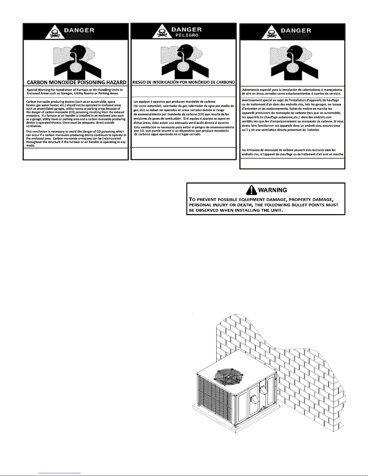
GROUND LEVEL INSTALLATIONS ONLY:
• When the unit is installed on the ground adjacent to the
building, a level concrete (or equal) base is recommended.
Prepare a base that is 3” larger than the package unit
footprint and a minimum of 3” thick.
• The base should also be located where no runoff of water
from higher ground can collect in the unit.
Outside Slab Installation
4
Page 5
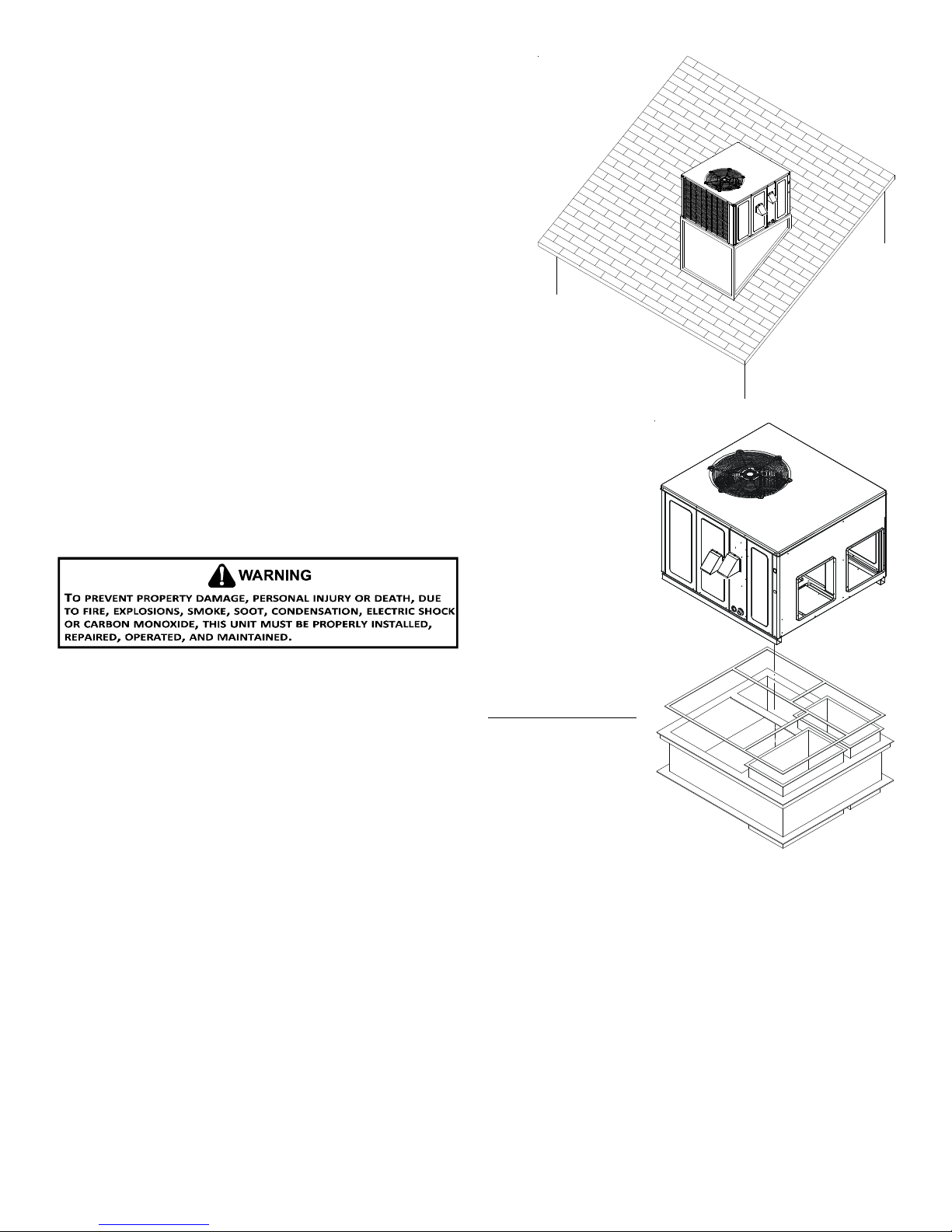
ROOFTOP INSTALLATIONS ONLY:
NOTE: To ensure proper condensate drainage, unit must be installed in
a level position.
• To avoid possible property damage or personal injury, the roof must
have sufficient structural strength to carry the weight of the unit(s)
and snow or water loads as required by local codes. Consult a
structural engineer to determine the weight capabilities of the
roof.
• The unit may be installed directly on wood floors or on Class A,
Class B, or Class C roof covering material.
• To avoid possible personal injury, a safe, flat surface for service
personnel should be provided.
ROOF CURB INSTALLATIONS ONLY:
• Sufficient structural support must be determined prior to locating
and mounting the curb and package unit.
Rooftop Installation
• Ductwork must be constructed using industry guidelines. The duct
work must be placed into the roof curb before mounting the package
unit.
• Curb insulation, cant strips, flashing and general roofing material are furnished by the
contractor.
GENERAL INFORMATION
This unit is approved for outdoor installation ONLY. Rated performance is achieved after
72 hours of operation.
unit specification sheet for split system models or product specification sheet for packaged
and light commercial models. Specification sheets can be found at www.goodmanmfg.com
for Goodman® brand products. Within the website, please select the residential or
commercial products menu and then select the submenu for the type of product to be
installed, such as air conditioners or heat pumps, to access a list of product pages that
each contain links to that model’s specification sheet.
To assure that your unit operates safely and efficiently, it must be installed, operated, and
maintained in accordance with these installation and operating instructions, all local building
codes and ordinances, or in their absence, with the latest edition of the National Fuel Gas
Code NFPA 54/ANSI Z223.1 and National Standard of Canada CAN/CSA B149 Installation
Codes.
The heating and cooling capacities of the unit should be greater than or equal to the
design heating and cooling loads of the area to be conditioned. The loads should be
calculated by an approved method or in accordance with A.S.H.R.A.E. Guide or Manual J - Load Calculations published by the Air
Conditioning Contractors of America.
Rated performance is delivered at the specified airflow. See outdoor
Roof Curb Installation
Obtain from:
American National Standards Institute
1430 Broadway
New York, NY 10018
TRANSPORTATION DAMAGE
Check the carton upon arrival for external damage. If damage is found, a request for inspection by carrier agent should be made in
writing immediately .
Carefully inspect the unit for damage including damage to the cabinetry. Any bolts or screws which may have loosened in transit
must be re-tightened. In the event of damage, the receiver should:
1. Make notation on delivery receipt of any visible damage to shipment or container.
2. Notify carrier promptly and request an inspection.
5
Page 6
3. In case of concealed damage, carrier should be notified as soon as possible-preferably within 5 days.
4. File the claim with the following supporting documents:
a. Original Bill of Lading, certified copy, or indemnity bond.
b. Original paid freight bill or indemnity in lieu thereof.
c. Original invoice or certified copy thereof, showing trade and other discounts or reductions.
d. Copy of the inspection report issued by carrier representative at the time damage is reported to the carrier. The carrier
is responsible for making prompt inspection of damage and for a thorough investigation of each claim. The distributor or
manufacturer will not accept claims from dealers for transportation damage.
NOTE: When inspecting the unit for transportation damage, remove all packaging materials. Recycle or dispose of the packaging
material according to local codes.
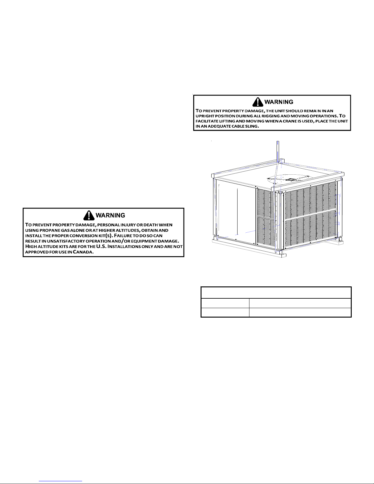
RIGGING DETAILS
IMPORTANT NOTE: If using bottom discharge with roof curb,
ductwork should be attached to the curb prior to installing the
unit. Ductwork dimensions are shown in roof curb installation
instructions.
Refer to the Roof Curb Installation Instructions for proper curb
installation. Curbing must be installed in compliance with the National
Roofing Contractors Association Manual.
Lower unit carefully onto roof mounting curb. While rigging unit, center
of gravity will cause condenser end to be lower than supply air end.
GAS PIPING
IMPORTANT NOTE: This unit is factory set to operate on natural gas at
the altitudes shown on the rating plate.
The rating plate is stamped with the model number, type of gas and gas
input rating. Make sure the unit is equipped to operate on the type of
gas available. Conversion to LP gas is permitted with the use of a factory
authorized conversion kit. Contact your distributor or refer to the
specification sheet for your model for a listing of approved LP gas
conversion kit(s). Refer to the Installation Manual provided with the
LP kit for conversion from natural gas to propane gas.
The minimum supply pressure should not vary from that shown in the
Inlet Gas Pressure table because this could prevent the unit from
having dependable ignition. In addition, gas input to the burners
must not exceed the rated input shown on the rating plate. Overfiring
of the unit could result in premature heat exchanger failure.
INLET GAS PRESSURE
Natural Min. 5.0" W.C., Max. 10.0" W.C.
Propane Min. 11.0" W.C., Max. 13.0" W.C.
Inlet Gas Pressure Must Not Exceed the Maximum Value Shown in
T able Above.
Rigging
HIGH ALTITUDE DERATE (U.S. INSTALLATIONS ONLY)
IMPORTANT NOTE: The gas/electric units naturally derate with altitude. Do not attempt to increase the firing rate by changing
orifices or increasing the manifold pressure. This can cause poor combustion and equipment failure. At all altitudes, the manifold
pressure must be within 0.3 inches W.C. of that listed on the nameplate for the fuel used. At all altitudes and with either fuel, the
air temperature rise must be within the range listed on the unit nameplate. Contact your distributor or refer to the specification
sheet for your model for listing of approved high altitude conversion kit(s). Refer to the Installation Manual provided with the high
altitude kit for altitude adjustments.
NOTE: No changes are required up to 2,000 feet. Use the appropriate high altitude kit above 2,000 feet.
PIPING
IMPORTANT NOTE: To avoid possible unsatisfactory operation or equipment damage due to under firing of equipment, do not
undersize the natural/propane gas piping from the meter/tank to the unit. When sizing a trunk line, include all appliances on that
line that could be operated simultaneously.
6
Page 7
The rating plate is stamped with the model number, type of gas and gas
g
)
input rating. Make sure the unit is equipped to operate on the type of
gas available. The gas line installation must comply with local codes, or in
the absence of local codes, with the latest edition of the National Fuel
Gas Code NFPA 54/ANSI Z223.1.
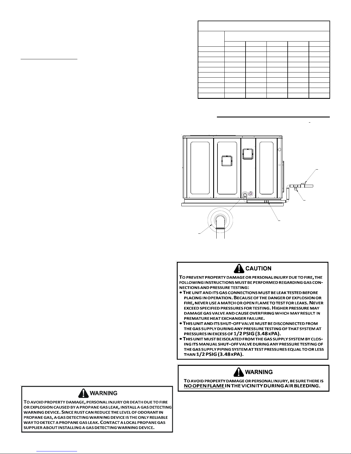
Natural Gas Connection
Refer to the Proper Piping Practice drawing for the general layout at the
unit. The following rules apply:
1. Use black iron pipe and fittings for the supply piping. The use of a
flex connector and/or copper piping is permitted as long as it is in
agreement with local codes.
2. Use pipe joint compound on male threads only. Pipe joint compound
must be resistant to the action of the fuel used.
3. Use ground joint unions.
4. Install a drip leg to trap dirt and moisture before it can enter the
gas valve. The drip leg must be a minimum of three inches long.
5. Use two pipe wrenches when making connection to the gas
valve to keep it from turning.
6. Install a manual shut-off valve in a convenient location (within
six feet of unit) between the meter and the unit.
7. Tighten all joints securely.
8. The unit must be connected to the building piping by one
of the following methods:
• Rigid metallic pipe and fittings
• Semirigid metallic tubing and metallic fittings (Aluminum
alloy tubing must not be used in exterior locations)
• Listed gas appliance connectors used in accordance with
the terms of their listing that are completely in the same
room as the equipment
• In the prior two methods above the connector or tubing
must be protected from physical and thermal damage.
Aluminum alloy tubing and connectors must be coated
to protect against external corrosion when in contact
GROMMET
with masonry, plaster or insulation or are subject to
repeated wettings by liquids (water - not rain water,
detergents or sewage)
NOTE: The unit gas supply entrance is factory sealed with
plugs. Keep plugs in place until gas supply is ready to be
installed. Once ready, replace the plugs with the supplied
grommets and install gas supply line.
Natural Gas Capacity of Pipe
in Cubic Feet of Gas Per Hour (CFH)
Length of
Pipe in Feet
10 132 278 520 1050 1600
20 92 190 350 730 1100
30 73 152 285 590 980
40 63 130 245 500 760
50 56 115 215 440 670
60 50 105 195 400 610
70 46 96 180 370 560
80 43 90 170 350 530
90 40 84 160 320 490
100 38 79 150 305 460
Pressure = .50 PSIG or less and Pressure Drop of 0.3" W.C. (Based
CFH =
Heatin
Nominal Black Pipe Size (inches)
1/2 3/4
on 0.60 Specific Gravity Gas)
1
1 1/4 1 1/2
BTUH Furnace Input
Va lu e o f Gas (BTU/Cubic Foot
GROUND JO INT UNION
(INSTALLED AHEAD OF GAS VALVE)
DRIP LEG
Proper Piping Practice
MANUAL
SHUT-OFF
VALVE
GAS PIPING CHECKS
There will be air in the gas supply line after testing for leaks on
a new installation. Therefore, the air must be bled from the
line by loosening the ground joint union until pure gas is
expelled. Tighten union and wait for five minutes until all gas
has been dissipated in the air. Be certain there is no open
flame in the vicinity during air bleeding procedure. The unit is
placed in operation by closing the main electrical disconnect
switch for the unit.
PROPANE GAS INSTALLATIONS
IMPORTANT NOTE: Propane gas conversion kits must be installed
to convert units to propane gas. Contact the distributor or
refer to the specification sheet for your model for the correct
LP conversion kit(s).
7
Page 8
All propane gas equipment must conform to the safety standards of the National Board of Fire Underwriters (See NBFU Manual 58).
For satisfactory operation, propane gas supply pressure must be within 9.7 - 10.3 inches W.C. at the manifold with all gas appl iances
in operation. Maintaining proper gas pressure depends on three main factors:
1. Vaporization rate, which depends on (a) temperature of the liquid, and (b) wetted surface area of the container or
containers.
2. Proper pressure regulation.
3. Pressure drop in lines between regulators, and between second
stage regulator and the appliance. Pipe size required will depend
on length of pipe run and total load of all appliances.
First Stage
Regulator
5 to 15 P SIG
(20 PSIG Max.)
Continuous
11" W.C.
TANKS AND PIPING
Complete information regarding tank sizing for vaporization,
recommended regulator settings and pipe sizing is available from most
regulator manufacturers and propane gas suppliers.
Since propane gas will quickly dissolve white lead or most standard
commercial compounds, special pipe dope must be used. Shellac base
compounds resistant to the actions of liquefied petroleum gases such
as Gasolac®, Stalactic®, Clyde’s® or John Crane® are satisfactory.
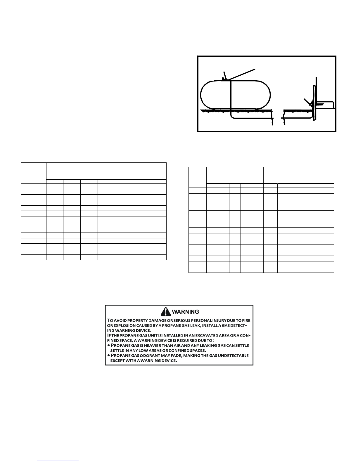
See Typical Propane Gas Piping figure for typical piping arrangement.
Sizing Between First and Second Stage Regulator
Maximum Propane Capacities listed are based on 1 PSIG Pressure Drop at 10
PSIG Setting. Capacities in 1,000 BTU/HR
PIPE OR
TUBING
LENGTH,
FEET
30 309 700 1,303 2,205 3,394 1,843 3,854
40 265 599 1,115 1,887 2,904 1,577 3,298
50 235 531 988 1,672 2,574 1,398 2,923
60 213 481 896 1,515 2,332 1,267 2,649
70 196 446 824 1,394 2,146 1,165 2,437
80 182 412 767 1,297 1,996 1,084 2,267
90 171 386 719 1,217 1,873 1,017 2,127
100 161 365 679 1,149 1,769 961 2,009
150 130 293 546 923 1,421 772 1,613
200 111 251 467 790 1,216 660 1,381
250 90 222 414 700 1,078 585 1,224
300 89 201 378 634 976 530 1,109
350 82 185 345 584 898 488 1,020
400 76 172 321 543 836 454 949
To convert to Capacities at 15 PSIG Settings -- Multiply by 1.130
To convert to Capacities at 5 PSIG Settings -- Multiply by 0.879
TUBING SIZE, O.D., TYPE L
3/8" 1/2" 5/8" 3/4" 7/8" 1/2" 3/4"
NOMINAL PIPE SIZE,
SCHEDULE 4 0
Sizing Between Single or Second Stage Regulator and Appliance*
Maximum Propane Capacities Listed are Based on 1/2" W.C. Pressure Dr op at
11" W.C. Setting. Capacities in 1,000 BTU/HR
PIPE OR
TUBING
LENGTH,
FEET
10 49 110 206 348 539 291 608 1,146 2,353 3,525
20 34 76 141 239 368 200 418 788 1,617 2,423
30 27 61 114 192 296 161 336 632 1,299 1,946
40 23 52 97 164 253 137 284 541 1,111 1,665
50 20 46 86 146 224 122 255 480 985 1,476
60 19 42 78 132 203 110 231 436 892 1,337
80 16 36 67 113 174 94 198 372 764 1,144
100 14 32 59 100 154 84 175 330 677 1,014
125 12 28 52 89 137 74 155 292 600 899
150 11 26 48 80 124 67 141 265 544 815
200 10 22 41 69 106 58 120 227 465 697
250 9 19 36 61 94 51 107 201 412 618
300 8 18 33 55 85 46 97 182 374 560
350 7 16 30 51 78 43 89 167 344 515
400 7 15 28 47 73 40 83 156 320 479
*DATA IN ACCORDANCE WITH NFPA PAMPHLET NO. 54
TUBING SIZE, O.D., TYPE L
3/8" 1/2" 5/8" 3/4" 7/8" 1/2" 3/4" 1" 1- 1/4" 1-1/2"
200 PSIG
Maximum
Second Stage
Regulator
Typical Propane Gas Piping
NOMINAL PIPE SIZE,
SCHEDULE 40
ELECTRICAL WIRING
THERMOSTAT LOCATION
Mount the thermostat approximately five feet above the floor, in an area that has an inside, vibration-free wall and has good air
circulation.
Movement of air must not be obstructed by furniture, door, draperies, etc. The thermostat must not be mounted where it will be
affected by drafts, hot or cold water pipes or air ducts in walls, radiant heat from fireplace, lamps, the sun, television, etc. Consult
the Instruction Sheet packaged with thermostat for mounting instructions.
Propane Gas Pipe Sizing
8
Page 9
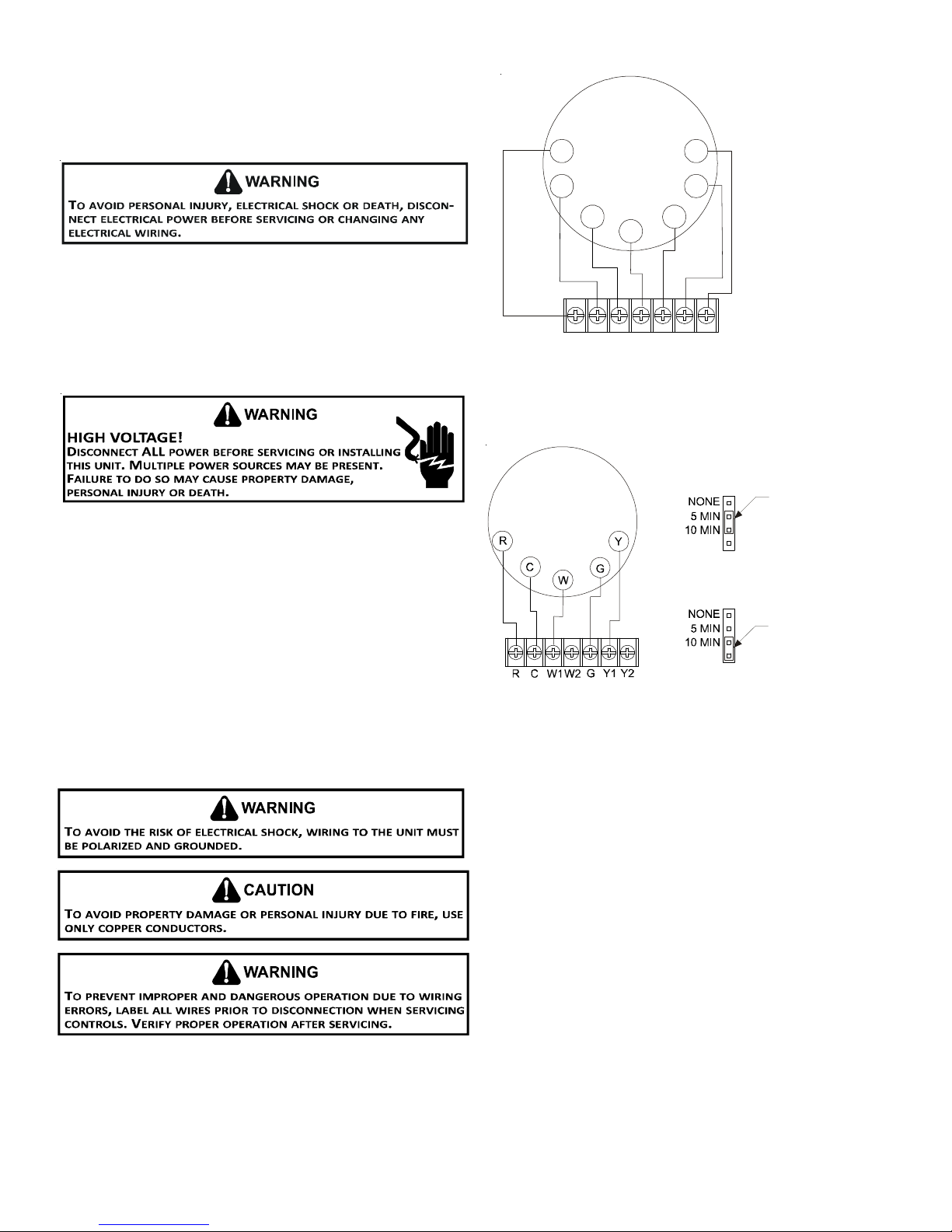
All units have two stages of heating and two stages of mechanical
cooling. Units which will have economizers may use thermostats
with two or three stages of cooling. All units can use single stage
or multi-stage thermostats. Refer to figures later in this section for
wiring.
Thermostat
R
CY1
Y2
Two-Stage Heating
with
Two-Stage Cooling
The units are designed for operation on 60 hertz current and at
voltages as shown on the rating plate. All internal wiring in the unit
is complete. It is necessary to bring in the power supply to the
contactor as shown on the unit wiring diagram which is supplied
with each unit. The low voltage wiring must be connected between
the unit control panel and the room thermostat.
SINGLE STAGE THERMOSTAT
To use a single stage thermostat, move jumper located to the
left of the terminal strip labeled “Stage Delay” from NONE to “5”
or “10” minutes. This selection will cause the control to run on
low stage for the selected time (5 or 10 minutes) then shift to
HIGH ST AGE. This option controls both cooling and heating modes.
If the jumper is not moved, only low-stage cool and low-stage
heat will operate.
W1
W2
R C W1W2
Two-Stage Heating with Two-Stage Cooling
G
I
ntegrated
GY1Y2
Thermostat Diagram
Control Module
5 MINUTE DELAY
PERIOD WI TH
JUMPER IN THIS
POSITION
10 MINUTE DELAY
PERIO D WITH
JUMPER IN THIS
POSITION
Refer to the unit wiring diagram for electrical connections. When
installed, the unit must be electrically grounded in accordance
with local codes or in the absence of local codes, with the
National Electrical Code, ANSI/NFPA No. 70, and/or the CSA C22.1 Electrical Code. Ensure low voltage connections are waterproof.
Two-Stage Heating (timed) and Two-Stage Cooling (timed)
with Single Stage Thermostat Diagram
9
Page 10

For unit protection, use a fuse or HACR circuit breaker that is in excess of the circuit ampacity, but less than or equal to the
maximum overcurrent protection device. DO NOT EXCEED THE MAXIMUM OVERCURRENT DEVICE SIZE SHOWN ON UNIT DATA PLATE.
All line voltage connections must be made through weatherproof fittings. All exterior power supply and ground wiring must be in
approved weatherproof conduit. Low voltage wiring from the unit control panel to the thermostat requires coded cable. See below
for ground level and rooftop wiring.
Note:Junct ion box locat ion
shown is optional and is
for illustrati on purpo s es only.
JUNCTION BOX
Electrical Power Directly To Junction Box
Electrical Power Rout e d Throug h Bottom of Unit
Typical Electrical Wiring Unit Voltage
UNIT VOLTAGE
The unit transformer is factory connected for 230V operation. If the unit is to operate on 208V, reconnect the transformer primary
lead as shown on the unit wiring diagram. The induced draft blower on some models is equipped with a low speed 230V lead (blue)
and a low speed 208V lead (black). If equipped, connect the induced draft blower low speed 208V lead (black) in place of the low
speed 230V lead (blue). Place the unused 230V lead on the “PARK” terminal located on ignition control.
HEAT ANTICIPATOR SETTING
The heat anticipator is to be set by measuring the load (amperage) at the “R” circuit. Follow the instructions provided with the
thermostat for more details.
10
Page 11
CIRCULATING AIR AND FILTERS
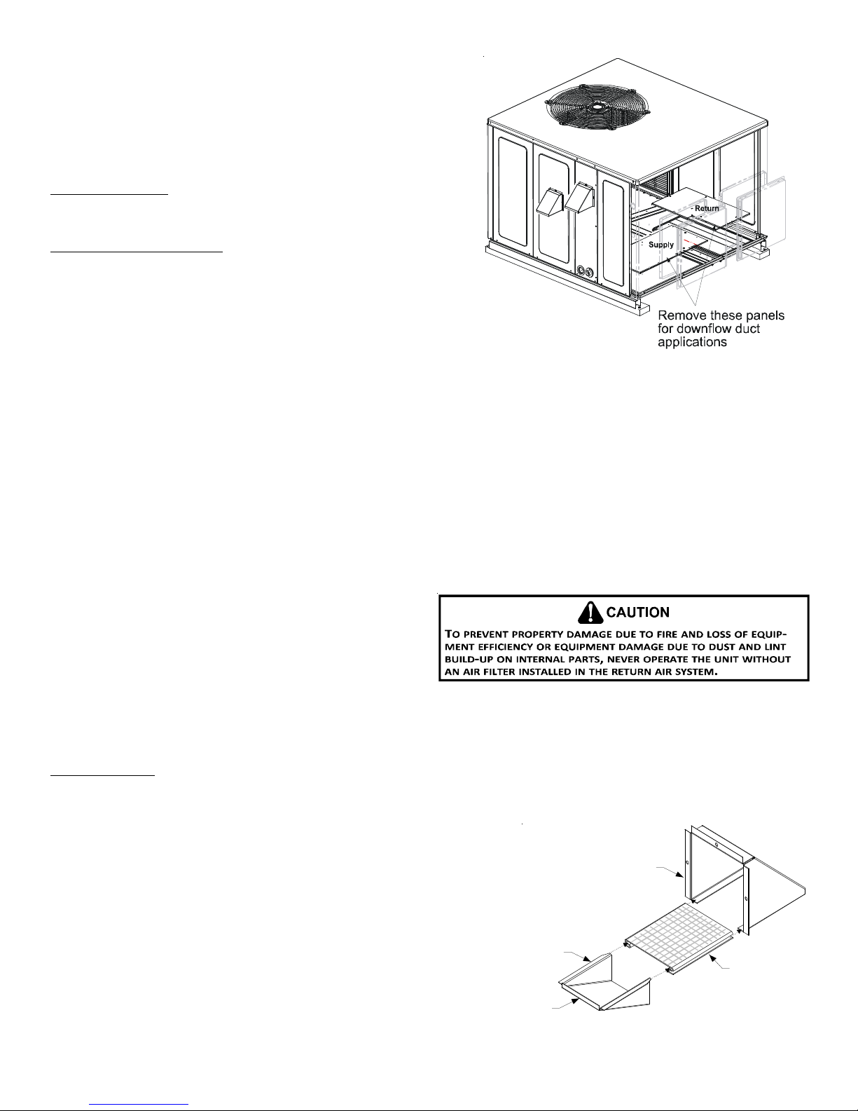
AIRFLOW CONVERSION
Units can easily be converted from horizontal to down-discharge airflow
delivery. In down-discharge or high static installations, the installer should
measure the total external static and review the blower performance
charts before performing the installation. In some installations it will be
necessary to change the blower speed to provide proper air flow.
Horizontal Air Flow
Single phase models are shipped without horizontal duct covers. If needed,
these kits may be ordered through Goodman’s Service Parts department.
Down Discharge Applications
Cut insulation around bottom openings and remove panels from the bottom
of the unit, saving the screws holding the panels in place.
NOTE: Single phase models require installation of horizontal duct kit
#20464501PDGK (medium chassis) and #20464502PDGK (large chassis).
DUCTWORK
Duct systems and register sizes must be properly designed for the C.F.M.
and external static pressure rating of the unit. Ductwork should be
designed in accordance with the recommended methods of Air
Conditioning Contractors of America Manual D (Residential) or Manual Q (Commercial). All ductwork exposed to the outdoors must
include a weatherproof barrier and adequate insulation.
A duct system should be installed in accordance with Standards of the National Board of Fire Underwriters for the Installation of Air
Conditioning, Warm Air Heating and Ventilating Systems. Pamphlets No. 90A and 90B.
The supply duct from the unit through a wall may be installed without clearance. However, minimum unit clearances as shown in the
appendix must be maintained. The supply duct should be provided with an access panel large enough to inspect the air chamber
downstream of the heat exchanger. A cover should be tightly attached to prevent air leaks.
For duct flange dimensions on the unit refer to the Unit Dimension illustration in the appendix.
For down-discharge applications, the ductwork should be attached to the roof curb prior to installing the unit. Ductwork dimensions
are shown in the roof curb installation manual.
If desired, supply and return duct connections to the unit may
be made with flexible connections to reduce possible unit
operating sound transmission.
Duct Cover Installation
FILTERS
Even though a return air filter is not supplied with this unit,
there must be a means of filtering all return air. All units may be
externally filtered.
Refer to the unit filter size chart in the appendix for filter size information.
Filters installed external to the unit should be sized in accordance with their manufacturer recommendations. A throwaway filter
must be sized for a maximum face velocity of 300 feet per minute.
Filter Installation
IMPORTANT NOTE: When installing a filter, the air flow arrows on the filter must point toward the circulator blower.
VENTING
NOTE: Venting is self-contained. Do not modify or block.
HOOD
INSTALLATION - FLUE HOOD EXHAUST
1. Locate the flue hood assembly box in the unit.
2. Slide screen over flanges on the lower flue hood.
3. Slide screen and lower flue hood into hood.
4. Using the three screws provided, attach the hood (with the opening
facing down) over the flue exhaust opening in the utility panel.
LOWER
FLUE
HOOD
LIP
SCREEN
11
Page 12

INSTALLATION - COMBUSTION AIR INTAKE HOOD
1. Locate the second hood.
2. Using the three screws provided, attach the hood (with
the opening facing down) to the heat exchanger access
door.
CONDENSATE DRAIN
CONDENSATE DRAIN CONNECTION
A 3/4” NPT drain connection is supplied for condensate piping. An
external trap must be installed for proper condensate drainage.
UNIT 2" MINIMUM
DRAIN
CONNECTION
NORMAL SEQUENCES OF OPERATION
FLEXIBLE
HEATING
This unit is equipped with an ignition control that automatically lights
the main burner. DO NOT attempt to light the main burners by any
other method.
1. Thermostat calls for low or high stage heating.
2. Induced draft blower energizes for 15-second pre-purge.
3. The spark igniter and low and high stage gas valve are energized
for 7 seconds. NOTE: The igniter produces a very intense
electrical spark that ignites the gas.
4. Main burners light and control detects presence of flame.
5. If the call is for low stage heat, the induced draft blower switches to low speed and the high stage gas valve closes 5
seconds after the main burners light. If call is for high stage heat, induced draft blower remains at high speed and high stage
gas valve remains open.
NOTE: If a single stage thermostat is used, the control will step to low stage after the main burners light and remain at low
stage for 5 or 10 minutes, depending on jumper position. If the call for HEAT remains after the transition delay time expires,
the control will transition from low stage to high stage.
6. The 30-second HEAT FAN ON delay time begins after the main burners light.
7. The unit delivers heat to the conditioned space until the thermostat is satisfied.
8. Gas valve(s) de-energizes. The induced draft blower continues operation for a 30-second post-purge.
9. Induced draft blower remains at low speed (or switches from high to low if operating at high stage heat) for the 30-second
post purge.
10. Ignition control begins timing the HEAT FAN OFF delay. There is an adjustable HEAT FAN OFF delay of approximately 90/120/
150/180 seconds (factory set at 150). If the unit is operating at high stage when the call for heat is removed, the blower will
operate for 30 seconds at high heat speed then switch to low heat speed for the remainder of the selected HEAT FAN OFF
delay.
NOTE: After the HEAT FAN OFF delay time has elapsed, the blower will de-energize. This allows any additional heat in the
heat exchanger to be transferred to the conditioned space.
TUBING-HOSE
OR PIPE
A POSITIVE LIQUID
SEAL IS REQUIRED
Drain Connection
3" MINIMUM
COOLING
1. Thermostat calls for low or high stage cooling.
2. If the thermostat call is for low stage cooling, the compressor and outdoor fan are energized at low stage. If the thermostat
call is for high stage cooling, the compressor and outdoor fan are energized at high stage.
3. The indoor blower will energize approximately 6 seconds later.
4. The unit delivers cooling to the conditioned space until the thermostat is satisfied.
12
Page 13

5. The compressor and outdoor fan will be de-energized when the thermostat opens.
6. The indoor blower continues to run at low cool speed for approximately 60 seconds after the thermostat is satisfied. This
allows additional cooling from the indoor coil to be transferred to the conditioned space. Then, the indoor blower is deenergized.
NOTE: A 180-second anti-short cycle is integral to the control and prevents recycling of the compressor.
FAN ONLY
1. Thermostat calls for FAN ONLY by energizing “G”.
2. The indoor blower is immediately energized at the low heat speed.
3. The indoor blower is immediately de-energized once thermostat call for FAN is removed.
STARTUP, ADJUSTMENTS, AND CHECKS
HEATING STARTUP
This unit is equipped with an electronic ignition device to automatically light the main burners. It also has a power vent blower to
exhaust combustion products.
On new installations, or if a major component has been replaced, the operation of the unit must be checked.
Check unit operation as outlined in the following instructions. If any sparking, odors, or unusual sounds are encountered, shut off
electrical power and check for wiring errors, or obstructions in or near the blower motors. Duct covers must be removed before
operating unit.
Heat Anticipator Setting
Set the heat anticipator on the room thermostat to 0.4 amps to obtain the proper number of heating cycles per hour and to
prevent the room temperature from overshooting the room thermostat setting.
Rollout Protection Control
The rollout protection device opens, cutting power to the gas valve, if the flames from
the burners are not properly drawn into the heat exchanger. The rollout protection
device is located on the burner bracket. The reason for elevated temperatures at the
control must be determined and repaired prior to resetting this manual reset control.
Rollout Protection
Rollout Protection on Burner Bracket
Secondary Limit Control
The secondary limit control is located on the top of the blower scroll assembly. This control
opens when elevated temperatures are sensed. Elevated temperatures at the control are
normally caused by blower failure. The reason for the opening should be determined and
repaired prior to resetting.
Secondary
Control Lim it
If the power to the unit is interrupted during the heating cycle, it may cause the secondary
limit to trip. Once the blower compartment temperature drops below the limit reset
temperature, the limit will automatically reset.
Pre-Operation Checks
1. Close the manual gas valve external to the unit.
2. Turn off the electrical power supply to the unit.
3. Set the room thermostat to its lowest possible setting.
4. Remove the heat exchanger door on the side of the unit by removing screws.
5. This unit is equipped with an ignition device which automatically lights the main burner.
Back of Unit
DO NOT try to light burner by any other method.
6. Move the gas control valve switch to the OFF position. Do not force.
7. Wait five minutes to clear out any gas.
Secondary Limit Control
8. Smell for gas, including near the ground. This is important because some types of gas
are heavier than air. If you have waited five minutes and you do smell gas, immediately
follow the warnings on page 3 of this manual. If having waited for five minutes and no gas smell is noted, move the gas control
valve switch to the ON position.
9. Replace the heat exchanger door on the side of the unit.
10. Open the manual gas valve external to the unit.
13
Page 14
11. Turn on the electrical power supply to the unit.
12. Set the thermostat to desired setting.
Open to
Atmosphere
Gas Supply And Manifold Check
Gas supply pressure and manifold pressure with the burners
operating must be as specified on the rating plate.
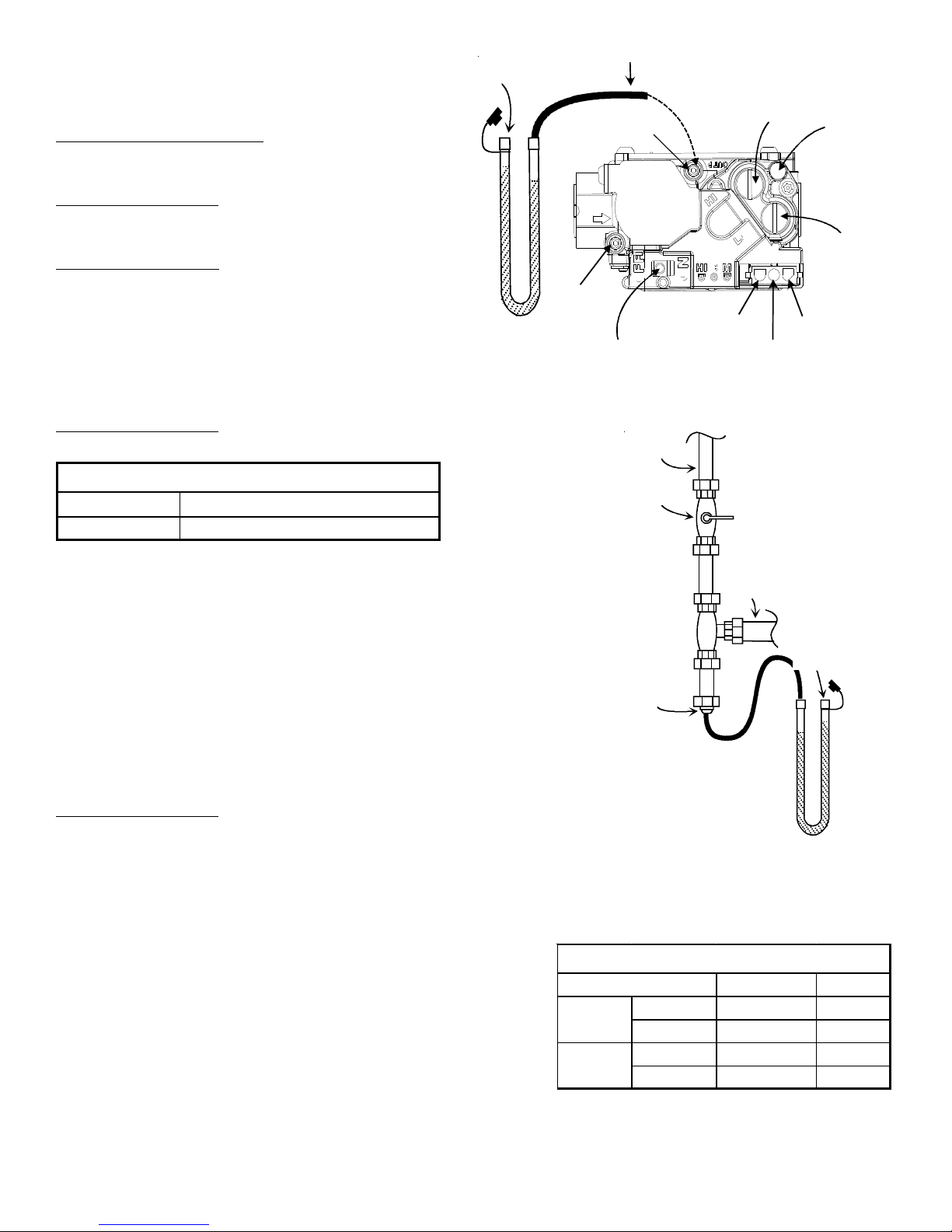
Gas Inlet Pressure Check
Gas inlet pressure must be checked and adjusted in accordance
to the type of fuel being consumed.
With Power And Gas Off:
1. Back inlet pressure test screw (inlet pressure boss) out
one turn (counterclockwise, not more than one turn).
Alternately, inlet gas pressure may be measured by
removing the cap from the drip leg and installing a predrilled
t
e
a
e
M
n
m
o
cap with a hose barb fitting.
2. Connect a water manometer or adequate gauge to the
inlet pressure tap of the gas valve (or hose barb fitting on
White-Rodgers Model 36G54 connected to Manometer
predrilled cap).
With Power And Gas On:
3. Put unit into heating cycle and turn on all other gas consuming appliances.
INLET GAS PRESSURE
Natural Min. 5.0" W.C., Max. 10.0" W.C.
Propane Min. 11.0" W.C., Max. 13.0" W.C.
m
o
a
n
M
s
H
o
Pressure Boss
Inlet
Pressure Boss
r
r
e
t
e
e
Outlet
On/Off Switch
Gas Line
Gas
Shutoff
Valve
High F ire Regulato r
High Fire
Coil Terminal (HI)
Terminal (C)
Adjust
A
Common
Regulator
Vent
Low Fire
Regulator Adjust
Coaxial Co il
Terminal (M)
NOTE: Inlet Gas Pressure Must Not Exceed the Maximum Value Shown. If operating
pressures differ from above, make necessary pressure regulator adjustments, check
piping size, etc., and/or consult with local utility.
4. Turn off all electrical power and gas supply to the system.
5. Remove manometer hose from the outlet pressure boss (or remove hose from
hose barb).
6. T urn inlet pressure test screw in to seal pressure port (clockwise, 7 in-lb minimum).
Alternately, remove predrilled cap from drip leg. Reinstall original cap, sealing
with pipe thread compound.
7. Turn on electrical power and gas supply to the system.
8. Turn on system power and energize valve.
9. Using a leak detection solution or soap suds, check for leaks at the pressure
boss screw (or drip leg cap). Bubbles forming indicate a leak. SHUT OFF GAS AND
FIX ALL LEAKS IMMEDIATELY.
Manifold Pressure Check
1 Turn OFF gas to furnace at the manual gas shutoff valve external to the furnace.
2. Turn off all electrical power to the system.
3. Back outlet pressure test screw (outlet pressure boss) out one turn
(counterclockwise, not more than one turn).
4. Attach a hose and manometer to the outlet pressure boss of the valve.
5. Turn ON the gas supply.
6. Turn on power and energize main (M) solenoid. Do not energize the HI
solenoid.
7. Measure gas manifold pressure with burners firing. Adjust manifold
pressure using the Manifold Gas Pressure table.
8. Remove regulator cover screw from the low (LO) outlet pressure
Natu ra l
regulator adjust tower and turn screw clockwise to increase pressure,
or counterclockwise to decrease pressure.
9. Energize main (M) solenoid as well as the HI terminal.
Propane
10. Remove regulator cover screw from the HI outlet pressure regulator
adjust tower and turn screw clockwise to increase pressure, or
counterclockwise to decrease pressure.
Gas Line
To Furnace
Open To
Atmosphere
Drip Leg Cap
With Fitting
Manometer Hose
Manometer
Measuring Inlet Gas Pressure
Alternate Method
Manifold Gas Pressure
Gas
Range Nominal
Low S tag e 1.7 - 2.3" w.c. 2.0" w.c.
Hig h Stag e 3.2 - 3.8" w.c. 3.5" w .c.
Low S tag e 5.7 - 6.3" w.c. 6.0" w.c.
Hig h Stag e 9.7 - 10.3" w.c. 10.0" w.c.
Manifold Gas Pressure
14
Page 15

11. Turn off all electrical power and gas supply to the system.
12. Remove manometer hose from outlet pressure boss.
13. Turn outlet pressure test screw in to seal pressure port (clockwise, 7 in-lb minimum).
14. Turn on electrical power and gas supply to the system.
15. Turn on system power and energize valve.
16. Using a leak detection solution or soap suds, check for leaks at pressure boss screw. Bubbles forming indicate a leak. SHUT
OFF GAS AND FIX ALL LEAKS IMMEDIATELY.
NOTE: For Natural gas to LP gas conversion, consult your dealer for appropriate conversion kit(s).
Gas Input (Natural Gas Only) Check
To measure the gas input use a gas meter and proceed as follows:
1. Turn off gas supply to all other appliances except the unit.
2. With the unit operating, time the smallest dial on the meter for one complete revolution. If this is a 2 cubic foot dial, divide
the seconds by 2; if it is a 1 cubic foot dial, use the seconds as is. This gives the seconds per cubic foot of gas being
delivered to the unit.
3. INPUT = GAS HTG VALUE x 3600 / SEC. PER CUBIC FOOT
Example: Natural gas with a heating value of 1000 BTU per cubic foot and 36 seconds per cubic foot as determined by Step 2, then:
Input = 1000 x 3600 / 36 = 100,000 BTU per Hour. NOTE: BTU content of the gas should be obtained from the gas supplier. This
measured input must not be greater than shown on the unit rating plate.
4. Relight all other appliances turned off in step 1. Be sure all pilot burners are operating.
Main Burner Flame Check
Flames should be stable, soft and blue (dust may cause orange tips but they must not be yellow) and extending directly outward
from the burner without curling, floating or lifting off.
Temperature Rise Check
Check the temperature rise through the unit by placing thermometers in supply and return air registers as close to the unit as
possible. Thermometers must not be able to sample temperature directly from the unit heat exchangers, or false readings could be
obtained.
1. All registers must be open; all duct dampers must be in their final (fully or partially open) position and the unit operated for
15 minutes before taking readings.
2. The temperature rise must be within the range specified on the rating plate.
NOTE: Air temperature rise is the temperature difference between supply and return air.
With a properly designed system, the proper amount of
temperature rise will normally be obtained when the unit is
operated at rated input with the recommended blower speed.
If the correct amount of temperature rise is not obtained, it
may be necessary to change the blower speed. A higher blower
speed will lower the temperature rise. A slower blower speed
O AVOID PERSONAL INJURY OR DEATH DUE TO ELECTRIC SHOCK, REMOVE
T
ELECTRICAL POWER FROM THE UNIT BEFORE CHANGING SPEED TAPS ON THE
BLOWER MOTOR.
WARNING
will increase the temperature rise.
NOTE: Blower speed MUST be set to give the correct air
temperature rise through the unit as marked on the rating plate.
External Static Pressure Check
The total external static pressure must be checked on this unit
to determine if the airflow is proper.
Blower Speed Adjustments
Blower speeds are changed at the indoor blower. The ignition
control board has four blower speeds: LOW HEAT, HI HEAT, LOW
COOL and HIGH COOL.
NOTE: FAN ONLY energizes at LOW HEAT speed. The GPG16 models
are equipped with EEM motors. EEM motors are constant torque
motors with very low power consumption. This motor is energized
by 24VAC. Adjust the CFM for the unit by changing the 24 VAC
leads to the speed terminal block on the motor.
15
Speed
Tap
T1
T2
HEATING COOLING
Lead
Definition
Low
Speed Heat
High
Speed Heat
Color
White T3
Brown T4
Speed
Tap
T5
Definition
Low Speed
Cool
High Speed
Cool
High Speed
Cool Hi-St a t ic
Lead
Color
Purple
Yellow
Page 16

NOTE: Heating airflow must be adjusted to provide the temperature rise shown on rating plate. Blower speeds are programmed to
deliver adequate airflow at rated external static pressure (ESP). Refer to airflow table provided in the Appendix for details.
Limit Check
Check limit control operation after 15 minutes of operation by blocking the
return air grille(s).
1. After several minutes the main burners must go OFF. Blower will continue to
run.
2. Remove air restrictions and main burners will relight after a cool down
period of a few minutes.
Adjust the thermostat setting below room temperature.
1. Main burners must go OFF.
LO COOL
HI COOL
LO HEAT
HI HEAT
U6
U7
U4
U3
U5
P1
K2
K1
2. Circulating Air Blower will continue to run for 90, 120, 150 or 180 seconds,
depending on the setting.
NOTE: If necessary, adjust fan OFF delay settings to obtain satisfactory comfort
level.
SPEEDUP
SW1
FAULT
BLOWER
RECAL L
OFF DELA Y
F1
STAGE
ECON
DEL AY
RCW1W2
GY1Y2
Unit Shutdown
1. Set the thermostat to lowest setting.
2. Turn off the electrical power supply to the unit.
3. Remove the heat exchanger door on the side of the unit
by removing screws.
4. Move the gas control valve switch to the OFF position. Do
not force.
5. Close manual gas shutoff valve external to the unit.
6. Replace the heat exchanger door on the unit.
7. If cooling and/or air circulation will be desired, turn ON
the electrical power.
COOLING STARTUP
NOTE: Check all manual reset limit controls in heating circuit if
cooling mode does not operate.
Compressor Protection Devices
The compressor includes components which are designed to
protect the compressor against abnormal operating conditions.
Cooling Refrigerant Charging (Models with TXV)
Check unit charge before putting the cooling section into full operation.
The unit has a thermostatic expansion valve metering device. To ensure the
unit is properly charged for the intended application, check the unit
refrigerant sub-cooling at the condenser. The refrigerant sub-cooling is a
function of outdoor ambient temperature and return air temperature of
the conditioned space. It is the installing contractors responsibility to ensure
the proper refrigerant sub-cooling at the condenser is adjusted for each
application. As the outdoor ambient temperature rises the sub-cooling
decreases and as the outdoor ambient temperature lowers, the sub-cooling
increases. NOTE: Proper sub-cooling adjustment optimizes cooling
performance. Models equipped with thermostatic expansion valve, charge
the system to sub-cooling, range shown on chart, when necessary, adjust
expansion valve stem for superheat setting.
NOTE: The expansion valve will not need adjustment for most applications.
Ensure system superheat is set within range listed on chart.
Control Board (Top)
Design superheat & subcooling
@ 95 °F ou t d oor ambient t em p erature
Models # Superhe at °F Subcooli ng ° F
GPG 162 4060M41 9 - 13 9 - 13
GPG1630080M41 8 - 12 10 - 14
GPG 163 6080M41 10 - 14 8 - 12
GPG 164 2100M41 10 - 14 6 - 10
GPG 164 8100M41 8 - 12 8 - 12
Superheat Adjustment
To adjust superheat, remove the control box cover and locate the expansion valve on the liquid line of the evaporator. Unscrew the
cover from the expansion valve, locate the adjustment screw, and turn it clockwise (in) to increase superheat or counterclockwi se
(out) to decrease superheat. Replace adjustment cap. Wait a minimum of 10 minutes between adjustments to allow time for the TXV
and pressures to stabilize.
16
Page 17

Cooling Operation
NOTE: Mechanical cooling cannot be reliably provided at ambient temperatures below 50° F.
1. Turn on the electrical power supply to the unit.
2. Place the room thermostat selector switch in the COOL position (or AUTO if available, and if automatic changeover from
cooling to heating is desired).
3. Set the room thermostat to the desired temperature.
TROUBLESHOOTING
IGNITION CONTROL ERROR CODES
The following presents probable causes of questionable unit operation. Refer to Diagnostic Indicator Chart for an interpretation of
the signal and to this section for an explanation.
Remove the control box access panel and note the number of diagnostic LED flashes. Refer to Diagnostic Indicator Chart for an
interpretation of the signal and to this section for an explanation.
FAULT RECALL
The ignition control is equipped with a momentary push-button switch that can be used to display on the diagnostic LED the last
five faults detected by the control. The control must be in Standby Mode (no thermostat inputs) to use the feature. Depress the
push-button switch for approximately 2 seconds. NOTE: Do not hold for longer than 4 seconds. Holding the button for 4 seconds
or higher will erase the memory! Release the switch when the LED is turned off. The diagnostic LED will then display the flash
codes associated with the last five detected faults. The order of display is the most recent fault to the least recent fault.
ABNORMAL OPERATION - HEATING
INTERNAL CONTROL FAILURE
If the integrated ignition control in this unit encounters an internal fault, it will go into a “hard” lockout and turn off the diagnostic
LED. If diagnostic LED indicates an internal fault, check power supply to unit for proper voltage, check all fuses, circuit breakers
and wiring. Disconnect electric power for five seconds. If LED remains off after restoring power, replace control.
EXTERNAL LOCKOUT
An external lockout occurs if the integrated ignition control determines that a measurable combustion cannot be established
within three (3) consecutive ignition attempts. If flame is not established within the seven (7) second trial for ignition, the gas valve
is de-energized, 30 second inter-purge cycle is completed, and ignition is re-attempted. The control will repeat this routine three
times if a measurable combustion is not established. The control will then shut off the induced draft blower and go into a lockout
state.
If flame is established but lost, the control will energize the circulator blower at the heat speed and then begin a new ignition
sequence. If flame is established then lost on subsequent attempts, the control will recycle the ignition sequence.
The diagnostic fault code is 1 flash for a lockout due to failed ignition attempts. The integrated control will automatically reset after
one hour, or it can be reset by removing the thermostat signal or disconnecting the electrical power supply for over five seconds.
If the diagnostic red LED indicates an external lockout, perform the following checks:
• Check the supply and manifold pressures
• Check the gas orifices for debris
• Check gas valve for proper operation
• Check flame sensor
A drop in flame signal can be caused by nearly invisible coating on the sensor. Remove the sensor and carefully clean
with steel wool.
• Auxiliary/Secondary Limit
A dirty filter, excessive duct static, insufficient air flow, a faulty limit, or a failed circulator blower can cause this limi t
to open. Check filters, total external duct static, circulator blower motor, blower motor speed tap (see wiring diagram),
and limit. An interruption in electrical power during a heating cycle may also cause the auxiliary limit to open. The
automatic reset secondary limit is located on top of the circulator blower assembly.
• Rollout Limit
If the burner flames are not properly drawn into the heat exchanger, the flame rollout protection device will open.
Possible causes are restricted or blocked flue passages, blocked or cracked heat exchanger, a failed induced draft
blower, or insufficient combustion air. The rollout protection device is a manual reset limit located on the burner
bracket. The cause of the flame rollout must be determined and corrected before resetting the limit.
• Check wiring
Check wiring for opens/shorts and miswiring.
IMPORTANT NOTE: If you have to frequently reset your gas/electric package unit, it means that a problem exists that should be
corrected. Contact a qualified servicer for further information.
PRESSURE SWITCH STUCK OPEN
A pressure switch stuck open can be caused by a faulty pressure switch, faulty wiring, a disconnected or damaged hose, a blocked
or restricted flue, a blocked pressure tap or a faulty induced draft blower.
17
Page 18

If the control senses an open pressure switch during the pre-purge cycle, the induced draft blower only will be energized. If the
pressure switch opens after ignition has begun the gas valve is de-energized, the circulator blower heat off cycle begins, and the
induced draft blower remains on. The diagnostic LED (red) code is two (2) flashes.
PRESSURE SWITCH STUCK CLOSED
A stuck closed pressure switch can be caused by a faulty pressure switch or faulty wiring. If the control encounters a pressure
switch stuck closed, the induced draft blower remains off. The diagnostic red LED code for this fault is three (3) flashes.
PRIMARY LIMIT
A primary limit will open due to excessive supply air temperatures. This can be caused by a dirty filter, excessive duct static,
insufficient air flow, or a faulty limit. Check filters, total external duct static, blower motor, blower motor speed tap (see wiring
diagram), and limit. This limit will automatically reset once the temperature falls below a preset level.
If a limit switch opens, the gas valve is immediately de-energized, the induced draft and air circulating blowers are energized. The
induced draft and air circulator blowers remain energized until the limit switch re-closes. The diagnostic LED (red) code for an
open limit is four (4) flashes.
NOTE: If the primary limit opens five (5) times within the same call for heat, the ignition control will lock out for one (1) hour with
the air circulating blower energized at high heat speed. The diagnostic LED (red) code for this condition is seven (7) flashes.
FLAME DETECTED WITH GAS VALVE CLOSED
If flame is detected with the gas valve de-energized, the combustion and air circulator blowers are energized. The diagnostic fault
code is five (5) flashes (red LED) for this condition. The flame diagnostic LED (amber) will flash (2) times to indicate this condition.
The control can be reset by removing the power supply to the unit or it will automatically reset after one hour. Miswiring is the
probable cause for this fault.
LOW FLAME SIGNAL
Under some conditions, the fuel or air supply can create a nearly invisible coating on the flame sensor. This coating acts as an
insulator causing a drop in the flame signal. If the flame signal drops below a predetermined value, the ignition control will display
an error code of (1) flash on the amber diagnostic LED. The unit will continue to operate until the control can no longer detect
flame.
ABNORMAL OPERATION - COOLING
SHORT CYCLE COMPRESSOR DELAY
The automatic ignition control has a built-in feature that prevents damage to the compressor in short cycling situations. In the
event of intermittent power losses or intermittent thermostat operation, the ignition control will delay output to the compressor
contactor for three minutes from the time power is restored or thermostat call for cooling is restored. (Compressor is off a total of
three minutes). The diagnostic red LED will flash six (6) times to indicate the compressor contactor output is being delayed.
NOTE: Some electronic thermostats also have a built-in compressor short cycle timer that may be longer than the three minute
delay given above. If you are using an electronic thermostat and the compressor has not started after three minutes, wait an
additional five minutes to allow the thermostat to complete its short cycle delay time.
HIGH PRESSURE SWITCH/LOSS OF CHARGE SWITCH
Some models include a high pressure cutout switch and/or a loss of charge cutout switch. The high pressure cutout switch
protects the refrigeration system from excessive operating pressures. The loss of charge cutout switch protects the refrigeration
system from very low operating pressures due to a loss of refrigerant. Compressor operation will be disabled if either of these
devices opens. If either devices opens, the diagnostic red LED will flash (9) times to indicate that a refrigeration system pressure
switch is open.
18
Page 19

MAINTENANCE
Have the gas heating section of the unit checked at least once
a year before the heating season begins, to be sure that the
combustion air inlet and flue outlet hoods are not blocked by
debris, which would prevent adequate combustion air and a
properly operating vent system.
FILTER REPLACEMENT OR CLEANING
A return air filter is not supplied with this unit; however, there must be a means of filtering all of the return air. The filter(s) may be
located in the return air duct(s), or return air filter grille(s). Consult with your installing dealer for the actual location of the return
air filter(s) for your unit.
Dirty filters are the most common cause of inadequate heating or cooling performance. Filter inspection should be made at least
every two months; more often if necessary because of local conditions and usage.
Dirty throwaway filters should be discarded and replaced with a new, clean filter. Dirty permanent filters should be washed wit h
water, thoroughly dried and sprayed with a filter adhesive before being reinstalled. (Filter adhesives may be found at many hardware
stores.) Permanent filters should last several years. However, should one become torn or uncleanable, it should be replaced.
CABINET FINISH MAINTENANCE
Use a fine grade automotive wax on the cabinet finish to maintain the finish’s original high luster. This is especially important in
installations with extended periods of direct sunlight.
CLEAN OUTSIDE COIL (QUALIFIED SERVICER ONLY)
The coil with the outside air flowing over it should be inspected annually and cleaned as frequently as necessary to keep the finned
areas free of lint, hair and debris.
CONDENSER, EVAPORATOR, AND INDUCED DRAFT MOTORS
Bearings on the air circulating blower motor, condenser motor and the combustion fan motor are permanently lubricated. No
additional oiling is required.
FLAME SENSOR (QUALIFIED SERVICER ONLY)
A drop in the flame current can be caused by a nearly invisible coating on the flame sensor. This
coating, created by the fuel or combustion air supply, can be removed by carefully cleaning the
flame sensor with steel wool.
NOTE: After cleaning, the microamp signal should be stable and in the range of 4 - 6 microamps
DC.
Flame
Sensor
FLUE PASSAGES (QUALIFIED SERVICER ONLY)
At the start of each heating season, inspect and, if necessary, clean the unit flue passage.
CLEANING FLUE PASSAGES (QUALIFIED SERVICER ONLY)
1. Shut off electric power and gas supply to the unit.
2. Remove burner assembly by disconnecting the gas line and removing the manifold bracket
from the partition panel.
3. Remove the flue from the induced draft blower and the collector box cover from the
partition panel.
4. The primary heat exchanger tubes can be cleaned using a round wire brush attached to a
length of high grade stainless steel cable, such as drain cleanout cable. Attach a variable speed reversible drill to the other
end of the spring cable. Slowly rotate the cable with the drill and insert it into one of the primary heat exchanger tubes.
While reversing the drill, work the cable in and out several times to obtain sufficient cleaning. Use a large cable for the
large tube, and then repeat the operation with a small cable for the smaller tube. Repeat for each tube.
5. When all heat exchanger tubes have been cleaned, replace the parts in the reverse order in which they were removed.
6. To reduce the chances of repeated fouling of the heat exchanger, perform the steps listed in “Startup, Adjustments, and
Checks”.
Flame Sensor
MAIN BURNER FLAME (QUALIFIED SERVICER ONLY)
Flames should be stable, soft and blue (dust may cause orange tips but must not be yellow). The flames must extend directly
outward from the burner without curling, floating or lifting off.
At least once a year, prior to or during the heating season, make a visual check of the burner flames.
NOTE: This will involve removing and reinstalling the heat exchanger door on the unit, which is held by two screws. If you are
uncertain about your ability to do this, contact a qualified servicer.
If a strong wind is blowing, it may alter the airflow pattern within the unit enough that an inspection of the burner flames is not
possible.
19
Page 20

CLEANING BURNERS
1. Shut off electric power and gas supply to the unit.
2. Remove the screws securing the manifold to the burner
retention bracket. Remove the manifold and rotate each
burner counterclockwise to remove.
3. Remove the burners.
4. Use a bottle brush to clean burner insert and inside of the
burners.
5. Replace burners and manifold, inspect the burner assembly
for proper seating of burners in retention slots.
6. Reconnect electrical power and gas supply.
For further information on the yearly inspection, consult the
User Manual. It is recommended that a qualified servicer inspect
and service the unit at least once each year.
Turn the unit on at the thermostat. Wait a few minutes, since
any dislodged dust will alter the normal flame appearance. Flames
should be predominantly blue and directed into the tubes. They
should not be yellow. They should extend directly outward from
the burner ports without curling downward, floating or lifting off the ports.
Chec k t he burner fla mes for:
1. Good adjustment
2. Stable, soft and blue
3. Not curling, floating, or lifting off.
Burner Flame
Burner
Burner
Bracket
ACCESSORIES AND FUNCTIONAL PARTS
SHEET METAL ACCESSORIES
Additional accessories can be purchased to fit specific application needs. Parts and
instructions are available from your distributor.
Manifold
FUNCTIONAL PARTS
FUNCTIONAL PARTS
Auxiliary Limit Switch Flame S e ns or
Blower Housing Gas Orifice
Manifold Assembly
Blower Whee l Gas Valve
Burner He at Exchan ger
Ci rculator Blower Motor High Limit Swi tch
Capa citor High Pre ss ure Switch
Compressor Igniter
Con denser Coil Ig ni t ion Contr ol
Condens e r Fan Blade Induce d Draft Blower
Condenser Fan Motor Pressure Switch
Contactor Pressure Switch Hose
Gas Manifol d Thermo static Expansi on Va lve
Evaporator Coi l Transformer
Fl a me Ro ll o ut Swi tch
Functional Parts List
GENERAL INFORMATION
1. Refer to the description in Functional Parts List when ordering any of the listed functional parts. Be sure to provide the
unit model and serial numbers with the order.
2. Although only functional parts are shown, all sheet metal parts, doors, etc. may be ordered by description.
3. Parts are available from your distributor.
20
Page 21

APPENDIX
IGNITION CONTROL DIAGNOSTIC INDICATOR CHART
Red Light Signal Refer to Abnormal Heating or Cooling Operation Sections of this Manual
Off Internal Control Failure
1 Flash External Lockout
2 Flashes Pressure Switch Stuck Open
3 Flashes Pressure Switch Stuck Closed
4 Flashes Thermal Protection Device Open
5 Flashes Flame Detected with Gas Valve Closed
6 Flashes Short Cycle Compressor Delay (Cooling Only)
7 Flashes Limit Opened Five (5) Times Within The Same Call For Heat
8 Flashes Indoor/Outdoor Thermostat Open (Cooling Only; Devices Not present On All Models)
9 Flashes High Pressure/Loss of Charge Switch Open (Cooling Only; Devices Not Present On All Models)
Amber Light Signal Refer to Abnormal Heating or Cooling Operation Sections of this Manual
Off No Flame Present
On Normal Flame
1 Flash Low Flame Current
2 Flashes Flame Detected with Gas Valve De-energized.
HEATING TIMING CHART
HIGH
Circulator
Blower
Gas V alve
LOW
OFF
HIGH
LOW
OFF
Igniter
Induced
Draft
Blower
Thermostat
Seconds
ON
OFF
HIGH
LOW
OFF
HIGH
LOW
OFF
0 15 22 27 52 0 30
COOLING TIMING CHART
Circulator
Blower
Compressor
Outdoor Fan
HIGH
LOW
OFF
HIGH
LOW
OFF
HIGH
LOW
OFF
90, 120, 150, 180
21
Page 22

UNIT DIMENSIONS
SUCTION/LIQUID PRE S SU RE PORT S
BEHIND COMPRESSOR ACCESS PANEL
COMBUSTION AIR INTAKE
HEAT EXCHANGE ACCESS PANEL
CONDENSATE DRAIN CO NNEC TIO N
F
O
R
E
Y
T
T
I
N
V
E
A
C
R
G
20
24
47
GAS SUPPLY ENTR ANCE
3/4" NPT FEMALE
FLUE EXHA UST
HOOD
C
4 3/4
16 1/8
19 1/8
7 5/16
7 7/8
POWER WIRE ENTRANCE
CONTROL WIRE ENTRANCE
18 7/16
FLUE EXHAUST
7 15/16
51
16
1 3/8
5 1/2
16
B
RETURN
LARGE
B
(INCHES)
SUPPLY
MEDIUM
3
EVAPORATOR/CONTROL PANEL ACCESS PANEL
DIMENSION
A3240
B1618
C9 1/214
A
2 3/4
5 1/4
COMBUSTION
AIR INTAKE
SUPPLY
EXH AU ST FLUE HOOD
BLOWER ACCESS PANEL
11
5 3/4
22
11
RETURN
22
22
Page 23

GPG16*****M41A** WIRING DIAGRAM
HPS
YL
BK
YL
BR
PU
CM
BK
BL
NGL
C
EM
T5T4T3T2
T1
WH
BR
PU
YL
LS
PS
ALS
RS
PU
M
GV
W. R.
GAS VALV E
C
OMPONENT LEGEND
ALS
CC
CM CONDENSER MOT OR
EM
F
FS
GND
GV
HPS
IGN
IIC
LS
ODF
PS
RCCF
RS
SOL
TR
VM
H
C
AUXILLARY LIMIT SWITCH
CONTACTOR
COMPRESSORCOMP
EVAPORATOR MOTOR
FUSE
FLAME SENSOR
EQUIPMENT G ROUND
GAS VAL VE
HIGHPRESSURE SWITCH
IGNITOR
INTEGRATED IGNITION CO NTROL
LIMIT SWITCH
OUTDOOR FAN
PRESSURESWITCH
RUN CAPACITOR FOR COMPRESSOR/FAN
ROLLOUT SW ITCH
SOLENOID(2ND STAGE COOL)
TRANSFORMER
VENT MOTOR
HIGH VOLTAGE!
M. F
ULTIPLE POWER SOURCES MAY BE PRESENT AILURE TO DO
SO MAY CAUSE PROPERTY DAMAGE, PERSONAL INJURY OR DEATH
YL
S
COMP
R
C
SOL
GR
PU
IGN
FS
OR
OR
YL
YL
PU
PU
PU
BR
BL
BL
VM
PURDBL
RD
1
2
1
2
F
ACTORY W IRING
LINE V OLTAGE
LOW VOLTAGE
OPTIONAL HIGH VOLTAGE
ELD WIRING
FI
HIGH VOLTAGE
LOW VOLTAGE
W
IRE CODE
BK BLACK
BL BLUE
BR BROW N
GR GREEN
GY GRAY
OR ORANGE
PK PINK
PU PURPLE
RD RED
WH WHITE
YL YELL OW
BK
PU
YL
RD
BK
BK
BL
PU
PU
PU
PU
PU
OR
FS
5
PU
LO COOL
4
BL
24VAC COM
3
YL
HI COOL
2
BR
HI HEAT
WH
1
LO HEAT
OR
OR
180
NONE
150
5MIN
120
10 MI N
90
STAGE
BLOWER
DELAY
OFFDELAY
YL
YL
PU
NOTES
1. REPLACEMENTWIRE MUST BE THE SAME SIZE AND TYPE OF
INSULATION AS ORIGINAL.(USE COPPER CONDUCTOR ONLY).
2. FOR 208 VOLT TRANSFORMEROPERATION MOVE BLACK WIRE
FROM TERMINAL 3 TO TERMINAL 2 ON TRANSFORMER.
3. USE COPPER CONDUCTORS O NLY
4. FOR 208V OPERATION, REMOVE BLUE LEAD FROM INDUCER LO W
TERMINAL. MOVE BLACK L EAD FROM PARK TERMINAL ONTO
INDUCER LOW TERMINAL. PLACE BLUE L EAD ON PARK TERMINAL.
5. USE NEC CLASS 2 WIRE FOR THERMOSTAT FIELD W IRING.
SEE NOT E 2
1
C
208
24V
BL
BL
L2
LOW
INDUCER
T1
P1
4
1
5
2
6
3
F
ECON
7
8
9
SEE
NOTE 4
RD
CC
RD
HIGH
YL
T2T1
L2L1
PU
BK
3TR2
240
BK
BKRDBL
BK
L1
YL
BL
BR
PU
SEE NOTE 5
LOW
RD
BK
BK
BK
BK
HI
PARK
ODF
3
6
5
2
4
1
YL
YL
Y1GW2W1CR
Y2
D ALL .
ISCONNECT POWER BEFORE SERVICING
YL
L1
L1
L1
YL
GND
SEE NOTE 3
PU
INTEGRATED IGNITION CONTROL
H
RCCF
0140G03218-A
YL
R
W1
W2
TO
MICRO
Y2
SEENOTE5
C
Y1
CONTROL
INTERGR A TE D IGNITION
YL
YL
TO
G
MICRO
DIAGNOSTIC
LED
RED
AMBER
JUNCTION
TERMINAL
INTERNALTO
INTEGRATED CONTROL
PLUG CONNECTION
SWITCH (PRESS.)
OVERCURRENT
PROT. DEVICE
POWER SUPPLY
208-230/1/60
SEENOTE3
PU
YL
P2
YL
PU
YL
RD
RDYLBR
CF
CC
P1
P2
2FLASHES
3FLASHES
4FLASHES
5FLASHES
7 FLASHES
8FLASHES
T1
LO
HI
LO
HI
L1
L1
TH
2
HLO
1
HLI
3
PSW
6
PSW
8
MVL
9
MVH
7
5
1
4
5
3
6
2
ECON
LO HEAT
HI HEA T
LO COO L
HI COOL
FLASHES
ON
OFF
1FLASH
6 FLASHES
9FLASHES
OFF
ON
1FLASH
2FLASHES
COMP
C
F
PS
ALS
COM
SOL
SOL
COMPR. SHORT CYCLE DELAY
LIMIT OPEN 5 TIM ES IN SAME
EQUIPMENT GROUND
FIELD GROUND
.
SUPPLY VOLTAGE
208-230/1/60
T2
R
S
H
RCC F
C
F
CM
SEENOTE4
VM
EM
3
1
2
SEE NOTE 2
TR
LS
GV
RS
M
H
MVC
C
HPS
CC
T1
T2
EM
C
T3
T4
STATUS CHECK
NORMAL OPERATION
NO POWER O R
INTERN ALCONTROL
FAULT
IGNITIONFAILURE
PRESSURESWI TCH OPEN
WITHOUT INDUCER ON
OPEN LIMIT SWI TCH
FALSE FLAME DETECTED
CALL FOR HE AT
IDT/ODT OPEN
PSW/LOC OPEN
NO FLAM E PR E SENT
NORMALFLAMEPRESENT
LOW FLAMESIGNAL
FALSE FLAME DETECTED
FIELD SPL ICE
L2
CC
L2
L2
L2
L2
-
CHECK INPUT POWER
CHECK FUSE(S)
REPLACE CONTROL
GAS FLOW
GAS PRESSURE
GAS VALVE
FLAME SENSOR
CHECK AUXIL IARY LI MI T SW.
CHECK ROLLOUT LIMIT SW.
CHECK PRESSURE SWITCH
CHECK TUBING
CHECK VENT MOTOR
CHECK PRESSURE SWITCHPRESSURESWITCH CLOSED
CHECK WIRING FOR SHORTS
CHECKMAINLIMITSWITCH
CHECK GAS V ALVE
CHECK FOR SHORTS IN
FLAME SENSO R WIRI NG
3MINCOMP. SHORT
CYCLE DELAY
CHECK MAIN LI MIT SWI TCH
CHECK AUXILI ARY LIMIT SW.
CHECKJ UMPER BETWEEN 1
AND 4 ON 6-CIRCUIT
CONNECTOR
CHECK REFRIGERANT
SWITCH ES FOR LOSS OF
CHARGE OR HIGH HEAD
PRESSURE
-
-
GAS FLOW
GAS PRESSURE
GAS VALVE
FLAME SENSO R
CHECK GAS VAL VE
CHECK FOR SHO R T S IN
FLAME SENSORWIRING
SWITCH (TEMP)
IGNITER
INTEGRATED IGNITION CONTROL
Wiring is subject to change. Always refer to the wiring diagram on the unit for the most up-to-date wiring.
23
Page 24

MINIMUM CLEARANCES
48" MIN
12" MIN
12" MIN
RECOMMENDED FILTER SIZES
UNIT 2 Ton 2 1/2 Ton 3 Ton 3 1/2 Ton 4 Ton
Min. Filter Size (1) 20 x 25 x1 (1) 25 x 25 x 1 (1) 25 x 25 x 1 (2) 20 x 20 x 1 (2) 20 x 20 x 1
3"
.
MIN
36" MIN
(FOR SERVICE)
NOTE: Roof overhang should be no more than 36".
24
Page 25

BLOWER PERFORMANCE DATA
E.S.P.
E.S.P.
E.S.P.
T1 LOW STAG E HEATING
SPEED
CFMWATTSRISE CFMWATTSRISE CFMWATTSCFMWATTSCFMWATTS
0.1
0.2
0.3
0.4
0.5
0.6
0.7
0.8 ---- ---- ---- 570 166 X ---- ---- 565 160 835 246
0.1
0.2
0.3
0.4
0.5
0.6
0.7
0.8 725 211 62 1,015 338 59 610 18 3 785 234 1,015 337
0.1
0.2
0.3
0.4
0.5
0.6
0.7
0.8 540 171 X 870 288 X 650 214 920 315 1,110 415
625 53 54 855 107 53 625 51 850 104 1,090 197
585 61 58 815 114 55 590 60 810 116 1,055 201
550 70 61 785 125 57 555 68 775 122 1,020 207
495 78 X 750 135
445 85 X 705 141
400 93 X 660 149
345 99 X 615 157
T1 LOW STAG E HEATING
SPEED
CFMWATTSRISE CFMWATTSRISE CFMWATTSCFMWATTSCFMWATTS
1,035 156 43 1,300 287 46 945 130 1,095 185 1,295 289
990 165 45 1,265 293 47 905 136 1,055 195 1,260 294
950 173 47 1,220 310 49 865 143 1,020 202 1,220 304
910 184 49 1,190 306
865 190 52 1,145 319
820 200 55 1,105 320
765 204 59 1,070 330
T1 LOW STAG E HEATING
SPEED
CFMWATTSRISE CFMWATTSRISE CFMWATTSCFMWATTSCFMWATTS
950 115 47 1,245 230 48 1,045 149 1,280 258 1,440 354
895 124 50 1,195 238 50 990 160 1,225 259 1,390 365
840 134 54 1,150 247 52 935 167 1,180 274 1,355 369
775 146 58 1,095 256
710 152 63 1,045 263
650 160 X 990 277
590 163 X 935 285
GPG1624060M41** - Rise Range: 35° - 65°
T2 HIGH STAGE HEATING
SPEED
GPG1630080M41** - Rise Range: 35° - 65°
T2 HIGH STAGE HEATING
SPEED
GPG1636080M41** - Rise Range: 35° - 65°
T2 HIGH STAGE HEATING
SPEED
T3 LOW STAGE
COOLING SP EED
505 79 735 129 995 212
60
450 86 705 136 955 230
64
410 93 655 147 915 240
X
330 101 600 154 8 80 255
X
T3 LOW STAGE
COOLING SP EED
815 152 970 210 1 , 180 313
50
770 160 930 215 1 , 140 319
52
715 173 885 222 1 , 105 326
54
660 173 840 233 1 , 055 334
56
T3 LOW STAGE
COOLING SP EED
875 179 1,130 280 1,300 383
55
820 186 1,085 293 1,260 396
57
755 194 1,030 295 1,210 402
61
700 197 975 304 1 , 160 397
64
T4 HIGH STAGE
COOLING SPEED
T4 HIGH STAGE
COOLING SPEED
T4 HIGH STAGE
COOLING SPEED
T5 COOLING SPEED
T5 COOLING SPEED
T5 COOLING SPEED
GPG1642100M41** - Rise Range: 35° - 65°
E.S.P.
E.S.P.
T1 LOW STAG E HEATING
SPEED
CFMWATTSRISE CFMWATTSRISE CFMWATTSCFMWATTSCFMWATTS
1,100 172 51 1,420 325 53 1,075 162 1, 335 274 1,620 484
0.1
1,040 181 54 1,360 331 55 1,015 172 1, 290 288 1,575 489
0.2
0.3
0.4
0.5
0.6
0.7
0.8 710 216 X 1,075 385 X 680 217 980 330 1,300 528
0.1
0.2
0.3
0.4
0.5
0.6
0.7
0.8 710 219 X 1,080 381 X 875 280 1,140 417 1 , 495 683
985 185 57 1,310 342 57 960 185 1,230 297 1,530 497
920 193 61 1,275 353
875 203 64 1,210 360
815 207 X 1,165 368
765 215 X 1,115 369
T1 LOW STAG E HEATING
SPEED
CFMWATTSRISE CFMWATTSRISE CFMWATTSCFMWATTSCFMWATTS
1,085 171 52 1,410 326 53 1,225 227 1, 475 367 1,790 641
1,035 178 54 1,365 329 55 1,190 240 1, 430 366 1,745 650
985 184 57 1,315 337 57 1,120 246 1,375 378 1,710 659
925 193 61 1,270 353
870 198 65 1,220 360
815 208 X 1,175 372
760 213 X 1,115 375
T2 HIGH STAGE HEATING
SPEED
GPG1648100M41** - Rise Range: 35° - 65°
T2 HIGH STAGE HEATING
SPEED
T3 LOW STAGE
COOLING SP EED
900 188 1,185 304 1,490 500
59
845 200 1,130 321 1,450 507
62
790 208 1,075 321 1,405 518
64
740 211 1,030 325 1,345 516
X
T3 LOW STAGE
COOLING SP EED
1,070 254 1,320 383 1,670 663
59
1,015 266 1,270 397 1,625 674
61
970 265 1,230 400 1,585 672
64
920 279 1,185 409 1,540 675
X
T4 HIGH STAGE
COOLING SPEED
T4 HIGH STAGE
COOLING SPEED
T5 COOLING SPEED
T5 COOLING SPEED
X = Outside of Temperature Rise Range Not Recommended.
NOTE:
The shaded area indicates ranges in excess of maximum external static pressure allowable when heating. For satisfactory operation,
external static pressure should not exceed 0.8" w.c.
25
Page 26

PACKAGE UNITS - DUAL FUEL & GAS
HOMEOWNER’S ROUTINE MAINTENANCE RECOMMENDATIONS
We strongly recommend a bi-annual maintenance checkup be performed
by a qualified service agency before the heating and cooling seasons begin.
REPLACE OR CLEAN FILTER
IMPORTANT NOTE: Never operate unit without a filter installed
as dust and lint will build up on internal parts resulting in loss of
efficiency, equipment damage and possible fire.
A return air filter is not supplied with this unit; however, there
must be a means of filtering the return air. An indoor air filter
must be used with your comfort system. A properly maintained
filter will keep the indoor coil of your comfort system clean. A
dirty coil could cause poor operation and/or severe equipment
damage.
The installer of your unit can tell you where your filter(s) are and how to clean or replace them.
Check your return filter(s) at least once every two months. When they are dirty, replace or clean as required. Disposable type
filters should be replaced. Reusable type filters may be cleaned.
NOTE: Reusable type filters should be washed with warm water, dried completely and sprayed with an adhesive according to
the manufacturers recommendations.
You may want to ask your dealer about high efficiency filters. High efficiency filters are available in both electronic and nonelectronic types. These filters can do a better job of catching small airborne particles.
Improper filter maintenance is the most common cause of inadequate heating or cooling performance. Filters should be cleaned
(permanent) or replaced (disposable) every two months or as required. When replacing a filter, it must be replaced with a filter of
the same type and size and always make certain the air flow arrows on the filter point in the proper direction.
CONDENSER, EVAPORATOR AND INDUCED DRAFT MOTORS
The bearings on the air circulating blower motor, condenser motor and the combustion fan motor are permanently lubricated and
require no further lubrication.
COMPRESSOR
The compressor motor is hermetically sealed and does not require additional oiling.
ANNUAL INSPECTION (QUALIFIED SERVICER ONLY)
Your package unit should be inspected by a qualified installer, or service agency at least twice every year. This check should be
performed before the heating and cooling seasons begin. This will ensure that adequate combustion air is being drawn and the vent
system is working properly. Particular attention should be paid to the following items. Repair as necessary.
• Check physical support of the unit. Ensure it is sound without any sagging, cracks, or gaps, around the base.
• Check for obvious signs of deterioration of the unit.
• Flue Hood and Combustion Air Inlet. Check for blockage (wasp nest, etc.) and corrosion.
F
LUE HOOD (QUALIFIED SERVICER ONLY)
• Return Air Connection. Check for physical soundness and ensure that the connection is firmly sealed to the package unit
casing.
• Heat exchanger. Check for corrosion and/or obstructions within the heat exchanger passageways.
• Burners. Check for proper ignition, burner flame, and flame sense.
• Wiring. Check wires for damage.Check electrical connections for tightness and/or corrosion.
• Filters. Check that filters are clean and in the proper placement in the unit or duct system.
• Louvers. Inspect air inlet louvers inside the heat exchanger compartments. Ensure the area is clean and free of dirt and
debris.
CLEAN OUTSIDE COIL (QUALIFIED SERVICER ONLY)
The outdoor coil should be inspected annually. It is important to keep the outdoor coil clean. Dirt, leaves, or debris could restrict
the airflow. If cleaning of the outdoor coil becomes necessary, hire a qualified servicer. Inexperienced people could easily puncture the tubing in the coil.
BEFORE CALLING YOUR SERVICER
• Check the thermostat to confirm that it is properly set.
• Check the disconnect switch near the unit to confirm that it is closed.
• Check the electrical panel for tripped circuit breakers or failed fuses. Reset the circuit breakers or replace fuses as
necessary.
•
Check for blockage of the indoor air inlets and outlets. Confirm that they are open and have not been blocked by objects
(rugs, curtains or furniture).
• Check for obstructions on the unit. Confirm that it has not been covered on the sides or the top. Remove any obstruction
that can be safely removed. If the unit is covered with dirt or debris, call a qualified servicer to clean it.
• Check the filter. If it is dirty, clean or replace it.
26
Page 27

Air Conditioning & Heating
Start-up Checklist
*Store in job file
Date: ___________________________________
ModelNumber: ___________________________________
SerialNumber: ___________________________________
Technician: ___________________________________
Pre Start-Up
(Checkeach itemascompleted)
Verify all packaging material has been removed.
Remove all shipping bracketsper installationinstructions.
Verifythe job site voltage agreeswith the unit serial plate.
Verifycondensate connection is installed per installation instructions.
Verifyproper clearance around the unit for safety, service, maintenance and proper unit operation.
Verifyproper weatherproofing of all ductwork, roof curbs and electrical connection s.
Location: __________________________________________
__________________________________________
__________________________________________
Unit#: __________________________________________
Check that the flue screen is in place.
Check gas piping for leaks.
Verifygaspressure to the unit is within the range specified on the serial plate.
Checktoensurethat all fans, pulleys and wheels are secure.
Check for proper belt tension and alignment per installationinstructions .
Check refrigerant piping for rubbing and leaks. Repair if necessary.
Check unit wiring to ensure it is not in contact with refrigerant piping or sharp metal edges.
Check all electrical connections and terminals. Tighten as needed.
Verifythat the crankcaseheaters have been energized for 24 hours.
Verify the scroll compressor(s) are rotating in the right direction .
Verify all accessories are installed and operating correctly.
Check filters and replace if necessary.
Verifythe installation of the thermostat.
9/2014
27
Page 28

Start-up Checklist
L
Air C onditioni ng & Heati ng
ELECTRICA
Supply Voltage
Circuit 1 Compressor Amps
Circuit 2 Compressor Amps
Blower Amps
Condenser Fan Amps
BLOWER EXTERNAL STATIC PRESSURE
Return Air Static Pressure
Supply Air Static Pressure
Total External Static Pressure
Blower Wheel RPM
TEMPERATURES
Start-Up
(Insert the values as each item is completed.)
L1 - L2 L2 - L3 L3 - L1
L1 L2 L3
L1 L2 L3
L1 L2 L3
Fan 1Fan 2Fan 3
IN. W.C.
IN. W.C.
IN. W.C.
RPM
Outdoor Air Temperature
Return Air Temperature
Co oling Supp ly A ir T em p eratur e
He ating Supply Air Temper ature
PRESSURES
Ga s Inlet Pressure
Ga s Manifold Pressure
Suction Circuit 1
Superh ea t (O rifice Sys t em)
Suction Circuit 2
Superh ea t (O rifice Sys t em)
Discharge Circuit 1
Subcooling (TXV Sys t em)
Discharge Circuit 2
Subcooling (TXV Sys t em)
DB WB
DB WB
DB WB
DB
IN. W.C.
IN. W.C. (Low Fire) IN. W.C. (High Fire)
PSIG °F
°F
PSIG °F
°F
PSIG °F
°F
PSIG °F
°F
(HEAT PUMP ONLY)
Suction Circuit 1
Suction Circuit 2
Discharge Circuit 1
Discharge Circuit 2
PSIG °F
PSIG °F
PSIG °F
PSIG °F
28
 Loading...