

Page 1
Service Instructions
®
TM
34.5" Chassis
ACVC96/AMVC96
GCVC96/GMVC96
Gas
Furnaces
This manual is to be used by qualified, professionally trained HVAC technicians only. Goodman does
not assume any responsibility for property damage or personal injury due to improper service
procedures or services performed by an unqualified person.
The material in this manual does not supercede manufacturer's installation and operation instructions
is a registered trademark of Maytag Corporation or its related companies and is used under license. All rights reserved.
RS6612010
August 2014
Copyright © 2014 Goodman Company, L.P.
Page 2
TABLE OF CONTENTS
IMPORTANT INFORMATION..................................... 2 - 5
PRODUCT IDENITIFICATION .................................. 6 - 10
ACCESSORIES .................................................... 11 - 13
INSTALLATION CONSIDERATIONS...................... 14 - 39
SYSTEM OPERATION.......................................... 40 - 44
TROUBLESHOOTING ........................................... 45 - 50
SYSTEM OPERATION COMFORTNET™ ............ 51 - 56
SERVICING .......................................................... 57 - 75
MAINTENANCE ................................................... 76 - 77
ACCESSORY WIRING DIAGRAMS ..................... 78 - 79
IMPORTANT INFORMATION
Pride and workmanship go into every product to provide our customers with quality products. It is possible, however,
that during its lifetime a product may require service. Products should be serviced only by a qualified service technician
who is familiar with the safety procedures required in the repair and who is equipped with the proper tools, parts, testing
instruments and the appropriate service manual. REVIEW ALL SERVICE INFORMATION IN THE APPROPRIATE
SERVICE MANUAL BEFORE BEGINNING REPAIRS.
IMPORTANT NOTICES FOR CONSUMERS AND SERVICERS
RECOGNIZE SAFETY SYMBOLS, WORDS AND LABELS
WARNING
T
O PREVENT THE RISK OF PROPERTY DAMAGE, PERSONAL INJURY, OR DEATH,
DO NOT STORE COMBUSTIBLE MATER IALS OR USE GASOLINE OR OTHER
FLAMMABLE LIQUIDS OR VAPORS IN THE VICINITY OF THIS APPL IANCE.
WARNING
G
OODMAN WILL NOT BE RESPONSIBLE FOR ANY INJURY OR PROPERTY DAMAGE ARISING FROM IMPROPER SERVICE OR SERVICE PROCEDURES.
I
F YOU INSTALL OR PERFORM SERVICE ON THIS UNIT, YOU ASSUME RESPONSIBILITY FOR ANY PERSONAL INJURY OR PROPERTY DAMAGE W HICH
MAY RESULT.
M
ANY JURISDICTIONS REQUIRE A LICENSE TO INSTALL O R SERVICE HEATING AND A IR CONDITIONING EQUIPMENT.
WARNING
HIGH VOLTAG E
D
ISCONNECT ALL POWER BEFOR E SERVICING OR
INSTALLING THIS UNIT.
BE PR ESENT.
DAMAGE, PERSO NAL INJURY OR DEATH.
FAILURE TO DO SO M AY CAU SE PROPERTY
MULTIPLE POWER SOURCES MAY
2
Page 3

IMPORTANT INFORMATION
Speci al Warning for Installation of Furnace or Air Handling Units in
Enclosed A reas such as Garage s, Utility Ro oms or Parki ng A r eas
Carbon monoxide producing devices (such as an auto mobile, space
heater, gas water heater, etc.) should not be operated in enclosed areas
such as un ve n tilated garages, ut ility rooms or parking areas because of
the danger of carbon mo noxide (CO) poisoning resulting from the exhaust
emissions. If a furnace or air handler is installed in an enclosed area such
as a garage, utility room or parking area and a carbon monoxide producing
device is operated therein, there must be adequate, direct outside
ventilation.
This ventilation is necessary to avoid the danger of CO poisoning which
can occur if a carbon monoxide producing device continues to operate in
the enclosed area. Carbon monoxide emissions can be (re)circu l a ted
throughout the structure if t he furnace or air han dler is operating in any
mode.
CO can cause serious illness in clud ing per man e nt brain dama ge or deat h.
To locate an authorized servicer, please consult your telephone book or the dealer from whom you purchased this
product. For further assistance, please contact:
CONSUMER INFORMATION LINE
GOODMAN® BRAND PRODUCTS
TOLL FREE
1-877-254-4729 (U.S. only)
email us at:
customerservice@goodmanmfg.com
fax us at: (731) 856-1821
(Not a technical assistance line for dealers.)
(Not a technical assistance line for dealers.) Your telephone company will bill you for the call.
CONSUMER INFORMATION LINE
AMANA® BRAND PRODUCTS
TOLL FREE
1-877-254-4729 (U.S. only)
email us at:
hac.consumer.affairs@amanahvac.com
fax us at: (731) 856-1821
(Not a technical assistance line for dealers.)
Outside the U.S., call 1-713-861-2500.
3
Page 4
IMPORTANT INFORMATION
FOR Y OUR S AFETY READ BEFORE OPERATING
If you do not follow these instructions exactly,
a fire or explosion may result causing property
damage, personal injury or loss of life.
A. This appliance does not have a pilot. It
is equipped with an ignition device which
automatically lights the burners. Do not
try to light the burners by hand.
B. BEFORE OPERATING smell around
the appliance area for gas. Be sure to
smell next to the floor because some gas
is heavier than air and will settle on the
floor.
WHAT TO DO IF YOU SMELL GAS
Do not try to light any appliance.
Do not touch any electric switch;
do not use any telephone in your
building.
Immediately call your supplier
from a neighbor's phone. Follow
the gas suppliers instructions.
If you cannot reach your gas supplier,
call the fire department.
C. Use only your hand to move the gas
control switch or knob. Never use
tools. If the gas control switch or knob
will not operate, don't try to repair it,
call a qualified service technician.
Force or attempted repair may result in
a fire or explosion.
D. Do not use this appliance if any part
has been under water. Immediately call
a qualified service technician to inspect
the appliance and to replace any part of
the control system and any gas control
which has been under water.
OPERATING INSTRUCTIONS
1. STOP! Read the safety information
2. Set the thermostat to lowest setting.
3. Turn off all electric power to the
appliance.
4. This appliance is equipped with an
automatic ignition system which
automatically lights the burners. Do not
try to light the burners by hand.
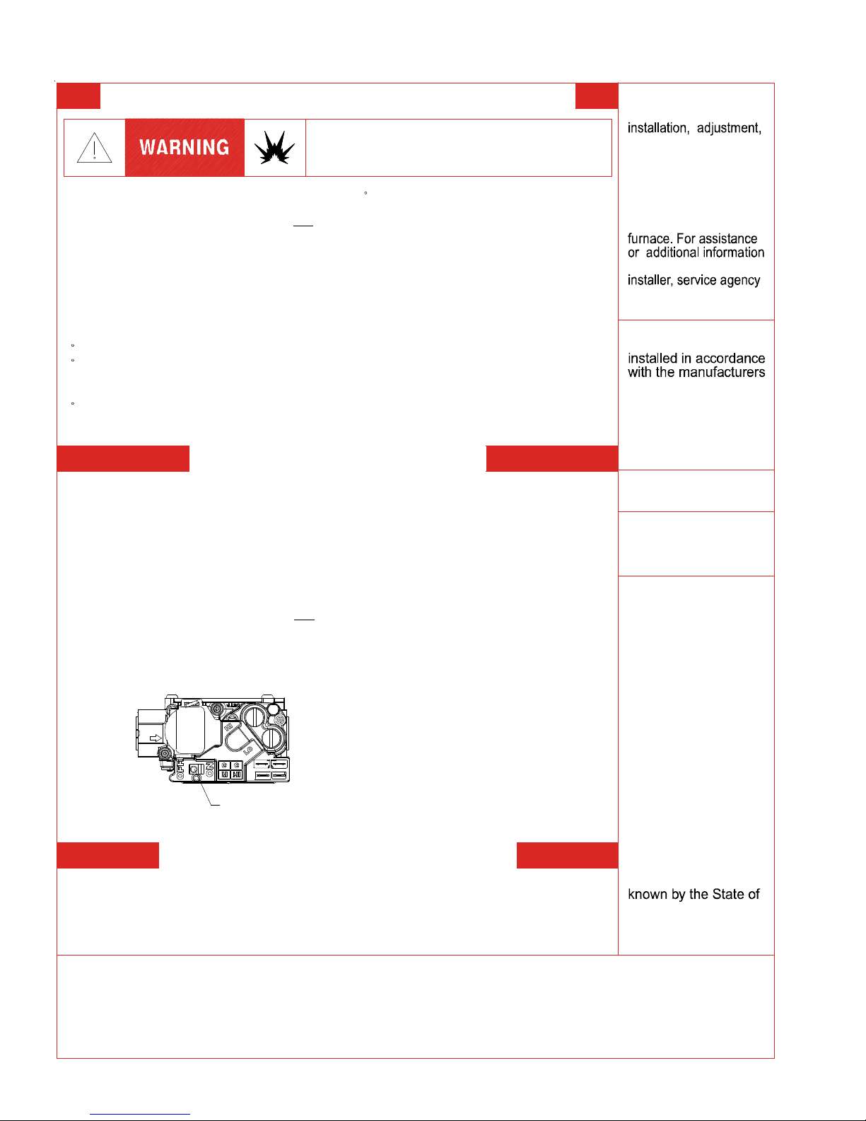
5. Remove control access panel.
6. Move the gas control switch or knob
to "OFF ".
GAS CONTROL
SWITCH SHOWN
IN "ON" POSITION
7. Wait five (5) minutes to clear out any
gas. If you then smell gas, STOP!above on this label.
Follow "B" in the safety information
above on this label. If you don't smell
gas, go to the next step.
8. Move the gas control switch or knob
to "ON".
9. Replace control access panel.
10. Turn on all electric power to the
appliance.
11. Set the thermostat to the desired
setting.
12. If the appliance will not operate,
follow the instructions "To Turn Off Gas
To Appliance" and call your service
technician or gas supplier.
TO TURN OFF GAS TO APPLIANCE
1. Set the thermostat to its lowest setting.
2. Turn off all electric power to the
appliance if service is to be performed.
3. Remove control access panel.
4. Move the gas control switch or knob
to "OFF". Do not force .
5. Replace control access panel.
WARNING: Improper
alteration, service or
maintenance can
cause injury or
property damage.
Refer to the user's
information manual
provided with this
consult a qualified
or the gas supplier.
This furnace must be
instructions and local
codes. In the absence
of local codes, follow
the National Fuel Gas
Code, ANSI Z223.1.
For indoor installation.
PGB & PGJ
For outdoor
installation only .
If notWARNING:
installed, operated
and maintained in
accordance with the
manufacturer's
instru ctions, this
product could expose
you to substances
in fuel combust ion
which can cause
death or serious
illness and which
are known to the
State of California to
cause cancer, birth
defects or other
reproductive harm.
This product contains
fiberglass insulation.
Fiberglass insu la tion
contains a chemic al
California to cause
cancer.
FOR YOUR SAFETY
other flammable vapors and liquids in the vicinity of this
or any other app liance.
4
Do not store or use gasoline or
0140F00001P
Page 5
IMPORTANT INFORMATION
CONSIGNES DE SECURITE - LIRE
AVANT D'ALLUMER L'APPAREIL
AVERTISSEMENT: Le non-respect des in structions qui suivent peut
^
entrainer un r i sque d'incendie ou d'explosion causant des dommages,
des blessures ou la mort.
A. Cet appareil comporte pas de veilleuse. Il est muni d'un mecanis m e qui allume
automatiquement le bruleur. N
B. Sentir tout autour de l'appariel AVANT D'ALLUMER afin de deceler toute fuite de gaz.
Assurez-vous de sentir tout pres du plancher car certains gaz sont plus lourds que l'air
et se deposeront sur le plancher.
SI VOUS SENTEZ UNE ODEUR DE GAZ:
Ne tentez d'allumer aucun appariel.
Ne touchez pas aux interrupteurs electriques; n'utiliser aucun telephone
dans l'edifice ou vous vous trouvez.
Appelez immediatement votre fournisseur de gaz en utilisant le telephone
d'un voisin et suivez les instructions du fournisseur.
Appelez les pompiers si vous ne parvenez pas a rejoindre votre fournisseur
de gaz.
C. N'utiliser que votre main pour pousser ou tourner le commande du gaz. N'utilisez
jamais d'outils. Si vous ne parvenez pas a pousser ou a t ourner la commande, ne tentez
pas de la reparer; appelez un reparateur qualifie. Forcer la commande ou essayer de la
reparer peut entrainer un risque d'incendie ou d'explosion.
D. N'utilisez pas cet appareil si l'une de ses parties a ete dans l'eau. Si cela se produit,
demandez immediatement a un reparateur qualifie d'insp ecter l'appareil et de remplacer
toute piece du systeme de controle et toute commande de gaz ayant ete dans l'eau.
^^
'allumez paz le bruleur manuellement.
^
^
0140F00002P
1. UN INSTANT! Lisez d'abord les consignes
INSTRUCTIONS DE SERVICE
d e securi te ci-dessus.
2. Reglez le thermostat a son point le plus bas.
3. Coupez l'alimentation electrique de l'appareil.
4. Cet appareil est muni d'un mecanisme qui
allume automatiquement le bruleur. Ne tentez
pa s d'allum er le bruleur manuellement.
5. Retirez le panneau d'acces de la commande.
6. Mettez la commande de gaz a la position
^
ARRET ("OFF").
7. Attendez cinq (5) minutes afin de permettre a
t ou t gaz present d'etre evacue. Si vous sentez
une odeur de gaz a ce moment, ARRETEZ! et
suivez les consignes de securite donnees au
paragraphe B ci-dessus. Si vous ne sentez pas
de gaz, passez a l'etape suivante.
8. Mettez la commande de gaz a la position
MARCHE ("ON").
9. Remettez la panneau d'acces de la commande
en plac e.
10. Retablissez l'alimenation electrique de l'appareil.
11. Reglez le thermostat a le temperature desiree.
12. Si l'appareil ne fonctionne pas, suivez les
instructions intitulees "Arret du gaz" et appelez un
reparateur qualifie ou votre fournisseur de gaz.
1. Reglez le thermostat a son point le plus bas.
2. Coupez l'alimentation electrique de l'appareil si vous devez effectuer un entretien.
3. Retirez le panneau d'acces de la commande.
4. Mettez la commande de gaz a la position ARRET ("OFF").
5. Remettez le panneau d'acces de la commande en p lace.
^
^
^
^
^
^
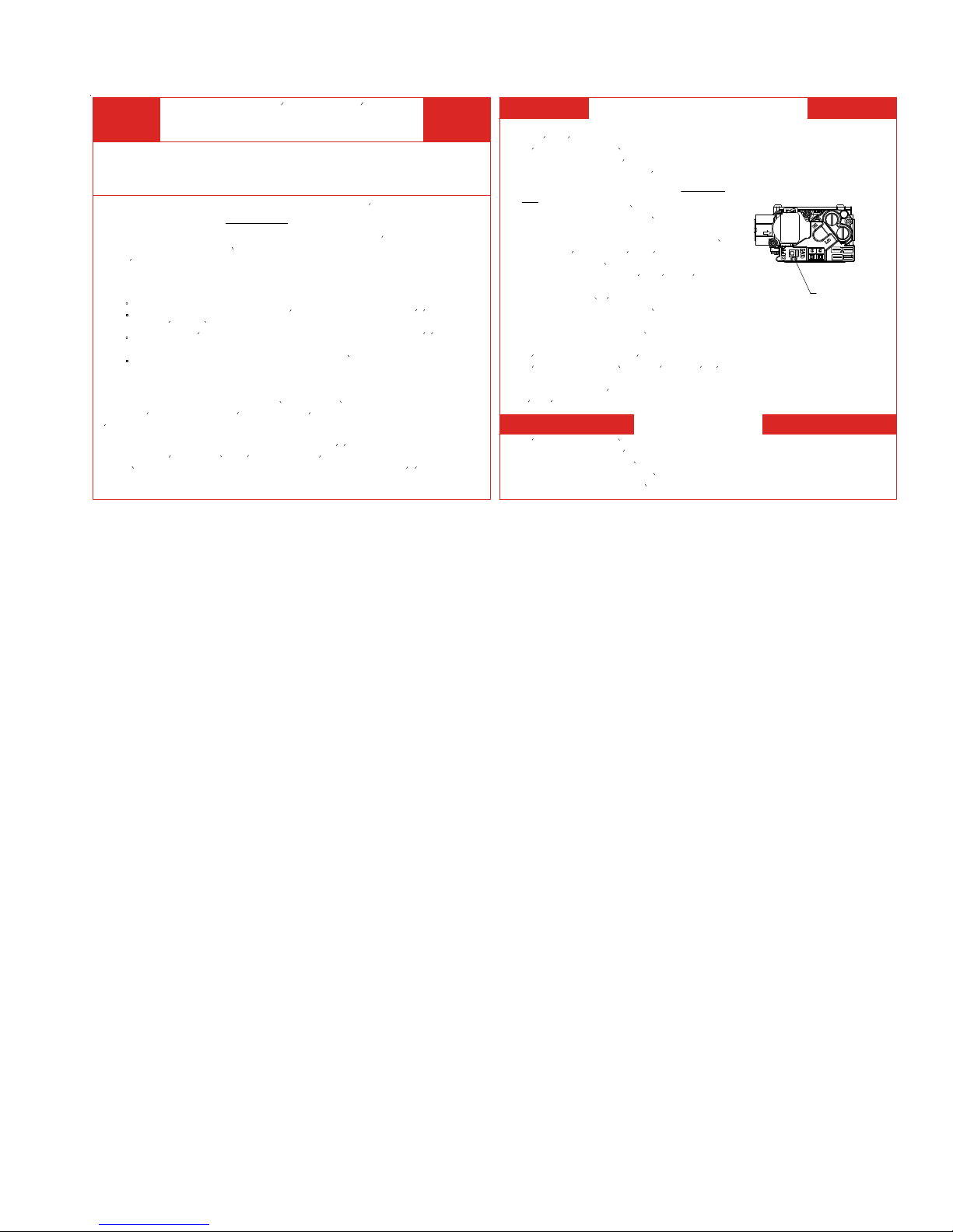
ARRET DU GAZ
Commande de
gaz en position
"MARCHE"
^
5
Page 6
PRODUCT IDENTIFICATION
The model and manufacturing number are used for positive identification of component parts used in manufacturing.
Please use these numbers when requesting service or parts information.
G M V C 96 080 4 C N A A
PRODUCT
TYPE :
G: Go od m a n
A: Amana®
Brand
D: A m ana®
Distinctions™
Brand
M: Upflo w/Horizon tal
D: De cidated Downflow
C: Downfl ow/Horiz on tal
H: High Air Flow
FURNACE
TYPE
E: T wo-Stage/
S: Single-Stage /
V: T wo Stage/
Spee d
H: Two Sta ge
Gas Valve -
SUPPLY TYPE
COMMUNICATION FEATURE
C: 4-Wire Communicatio n Ready
X-13 Mot or
Multi-Speed
Varia ble-
Multi-Speed
NOMI NAL I NPUT
040: 40,000 Bt uh
060: 60,000 Bt uh
080: 80,000 Bt uh
100: 100,000 Bt uh
120: 120, 000 B tu h
AFUE
8: 80%
9: 90%
95: 95 %
AIRFLOW
CA PABILITY
@ 0.5" E SP
3: 12 00
4: 16 00
5: 20 00
CABINET
WIDTH
A: 14"
B: 17- 1 /2"
C: 21 "
D: 24 - 1 /2"
MAJOR REVIS ION
A: In itial R e le ase
MI NOR REVI S ION
A: In itial R e le ase
ADDITIONAL
FEA TURE S
N: Natural Gas
X: L o w N O x
6
Page 7
PRODUCT IDENTIFICATION
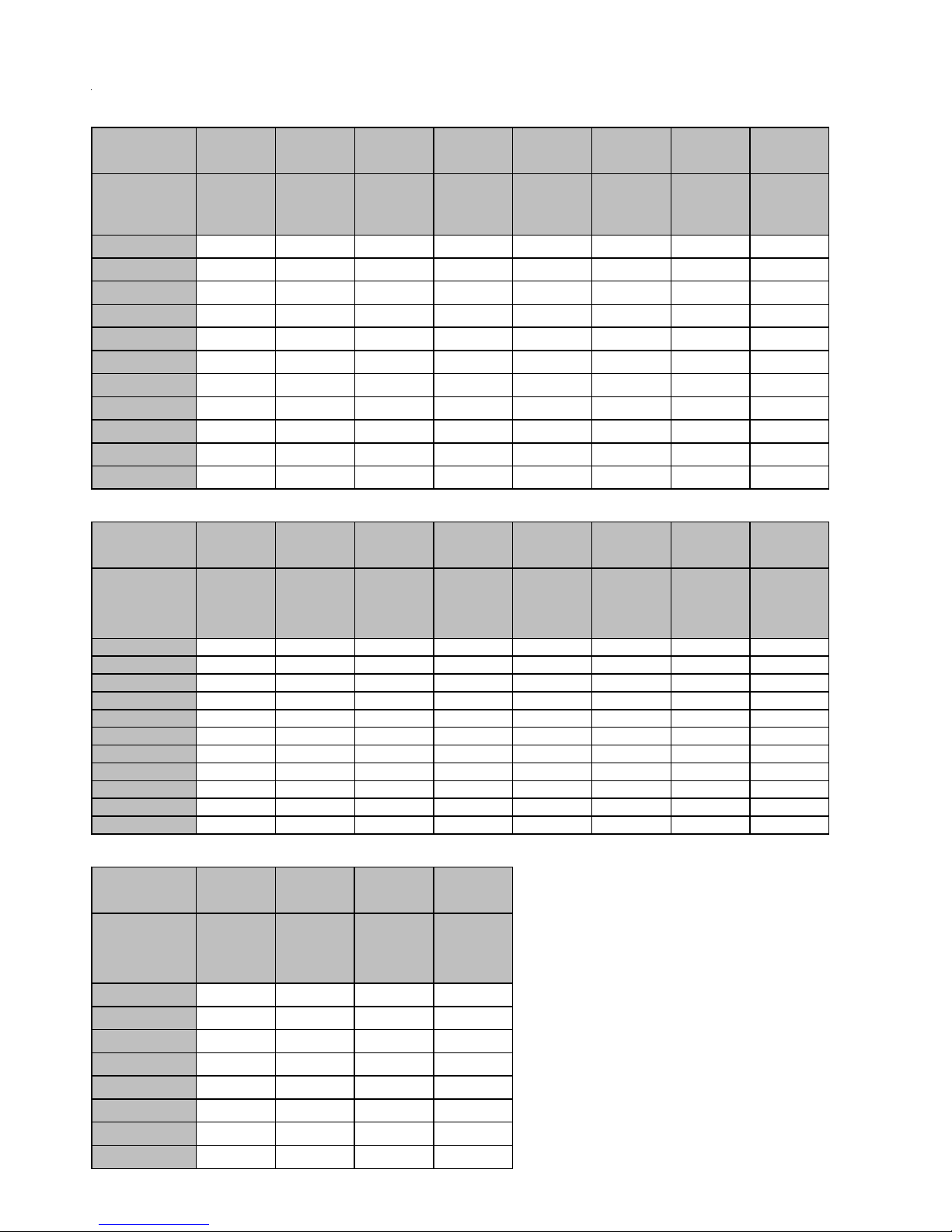
MODEL: GMVC96 REV AA
Equipment Ty pe Goodman Brand Residential Gas Furnace
Heating Stages Two
Cooling Stages Two
Control Type ClimateTalk
Blowe r Motor Type 4 Wire Variable Speed ECM
GMV C96
Installation Positions
BTUH Input Low Fire (X 1000)
BTUH Input High Fire (X 1000)
A/C Capable Tons
Cabinet Hig ht "
Cabinet Width "
Heating CFM @ 100% Firing Rate
Draft Inducer
Gas Valve
24 VAC Heating Inputs
24 VAC Cooling Input s
Primary He at Exchanger
Accessory Terminals
Gas Line Entry
Revision Attributes
Two Speed
Two Stage
W1 / W2
Y1 / Y2
Alum inized Steel
EAC terminal, Field Powered H UM IN / HUM OUT terminals, Single Hu m termi nal
powered simultaneously with draft inducer, AUX circuit
Left or Right
First revision of 34.5" two stage commu nicating capable up flow furnace
MODEL: AMVC96
Equipment Type Amana Brand Residential Gas Furnace
Heating Stages Two
Cooling Stages Two
Con tro l Type ClimateTalk
Blower Motor Type 4 Wire Variable Speed ECM
™ or Conventional 24 Volt
0403BN 0603BN 0803BN 0804CN 1005CN 1205DN
UF, Hor L/R UF, Hor L/R UF, Hor L/R UF, Hor L/R UF, Hor L/R UF, Hor L/R
30 45 60 60 75 90
40 60 80 80 100 120
1.5 - 3 1.5 - 3 1.5 - 3 2 - 4 1.5 - 5 2 - 5
34.5 34.5 34.5 34.5 34.5 34.5
17.5 17.5 17.5 21 21 24.5
553 1059 1316 1337 1870 1940
REV AA
™ or Conventional 24 Volt
MODEL: GCVC96 REV AA
Equipment Typ e Goodman Brand Residential Gas Furnace
Heating St a ge s Two
Cooling Stages Two
Con t rol Type ClimateTalk
™ or Conventional 24 Volt
Blow e r Mo tor Ty p e 4 Wire Variable Speed ECM
GCV C9 6
Installati on P ositions CF, Hor L/R CF, Hor L/R CF, Hor L/R CF, Hor L/R CF, Hor L/R CF, Hor L/R
BTUH Input Low Fire (X 1000) 30 45 60 60 75 90
BTUH Input Hi gh Fire (X 1000) 40 60 80 80 100 120
A/C Capable Tons 1.5 - 3 1.5 - 3 2 - 4 2 - 4 2 - 5 2 - 5
Cabinet Hi ght " 34.5 34.5 34.5 34.5 34.5
Cabinet Width " 17.5 17.5 21 21 24.5
Heating CFM @ 100% Firing Rate 1059 950 1146 1325 1797 1827
Draft Inducer
Gas V alve
24 VAC Heating Inputs
24 VAC Cooling Inputs
Primar y Heat Exchanger
Accessory Terminals
Gas L ine Entry
Revisi o n Attr i butes
0403BN 0603BN 0803BN 0804CN 1005CN 1205DN
Two Speed
Two Stage
W1 / W2
Y1 / Y2
Aluminized Steel
EAC termina l, Field Powered HUM IN / HUM OUT terminals, Single Hum term inal
powe red simultaneously wit h draft inducer, AUX circuit
Left or Right
First revi sion of 34.5" modulating counter fl ow furnace
MODEL: ACVC96 REV AA
Equipment Ty pe Amana Bra nd Residential Gas Furnac e
Heating Stages Two
Coo lin g Stages Two
Cont ro l Ty pe ClimateTalk
Blowe r M o tor Type 4 Wire Variable Speed ECM
™ or Conventional 24 Volt
AMVC96
Ins tallation Positions
BTUH Input Low Fire (X 1000)
BTUH Input High Fi re (X 1000)
A/C Capable Tons
Cabinet Hight "
Cabinet Width "
Heating CFM @ 100% Firing Rate
Draft Inducer
Gas Valve
24 VAC Heating Inputs
24 VAC Cooling Inputs
Primary Heat Exchanger
Accessory Terminals
Gas Line Entry
Revi sion Attributes
0403BN 0603BN 0803BN 0804CN 1005CN 1205DN
UF, Hor L/R UF, Hor L/R UF, Hor L/R UF, Hor L/R UF, Hor L/R UF, Hor L/R
30 45 60 60 75 90
40 60 80 80 100 120
1.5 - 3 1.5 - 3 1.5 - 3 2 - 4 1.5 - 5 2 - 5
34.5 34.5 34.5 34.5 34.5 34.5
17.5 17.5 17.5 21 21 24. 5
553 1059 1316 1337 1870 1940
Two Speed
Two Stage
W1 / W2
Y1 / Y2
Stainless Steel
EAC terminal, Field Powered HUM IN / HUM OUT term i nals, Single Hum terminal
powered simultaneously with draft induce r, AUX circuit
Left or Right
Firs t r evision o f 34.5" two st ag e c o mmunicating c apable u p flow furn ac e
ACVC96
Inst allatio n Positi o n s CF, Hor L/R CF, Hor L/R CF, Hor L/R CF, Hor L/R CF, Hor L/R CF, Hor L/R
BTUH Input Low Fire (X 1000) 30 45 60 60 75 90
BTUH Input High Fire (X 1000) 40 60 80 80 100 120
A/C Capable Tons 1.5 - 3 1.5 - 3 2 - 4 2 - 4 2 - 5 2 - 5
Cabinet Hight " 34.5 34.5 34. 5 34.5 34.5
Cabinet Width " 17.5 17.5 21 21 24.5
Heating CFM @ 100% Firing Rate 1059 950 1146 1325 1797 1827
Draft Inducer
Gas Valve
24 VAC Heating Inputs
24 VAC Cooling Inputs
Primary Heat Ex changer
Accessory Terminals
Gas Line Entry
Revision Attributes
0403BN 0603BN 0803BN 0804CN 1005CN 1205DN
Two Speed
Two Stage
W1 / W2
Y1 / Y2
Stainless Steel
EAC terminal, Field Powered HUM IN / HUM OUT term in als, Singl e Hum terminal
powered simul taneously with draft inducer, AUX circuit
Left or Right
First revision of 34.5" modulating counter flow furnace
7
Page 8
PRODUCT IDENTIFICATION
MODE L # MFG # DESCRIPTION
AFE18-60A
AMU1620
AMU1625
AMU2020
AMU2025
GMU1620
GMU1625
GMU2020
GMU2025
ASAS-10
ASAS-11
ASAS-12
ASAS-18
CFSB17
CFSB21
CFSB24
N/A
P1251305F
P1251306F
P1251307F
P1251308F
N/A
P1251301F
P1251302F
P1251303F
P1251304F
N/A
Fo ssil Fuel K it.
above/do wnstream of a gas or f ossil fuel f urnace when used wit h a hea t pump. It will operate
with single and t wo stage hea t pumps and single and two stage f urnaces. The AFE 18-60A
cont rol will tu r n the heat pu mp unit off wh en the f ur nace is turned on. An ant i- short cycle
feature initiates a 3 minute timed off d elay when the compressor goes of f.
Med ia Air Cl eaner.
fur n ac e models. The Amana (A MU*) and Goodman (GMU*) Media Air Cleaner is a high
efficienc y air fil trat ion device designed to r emove dirt, dust , pollen and other microscopic
particles from th e a ir passing thro ugh it. Flexible performance range u p to 2, 000 C FM
capac ity. The air cl eaner should be installed in the system so that all the sy stem air is
circ ulated thr ou gh t he air c leaner . The air cle aner will only remove t he air b orne contaminant s
delivered to it. Maximum per formance is obtained when the syst em blower is set f or
cont in uous operation. Carbon filters (opt io nal) are available.
Electronic Air Cleaner.
Brand furnace models. T he H igh- Efficiency Electronic Air Cleaner i s designed to r emove air
cont aminant s down to .01 micr ons. Car b on filt er s (optional) re move odors. D ual in dic ator
lights show unit operation a t a glance. Electronic pr o ving switch cycles the air c lea ner On/ Off
with the system f an . Durable powder-coat paint finish resists corrosion.
C ounterflow S ubbase K it.
models ACV C9 an d GCVC9. These kits are available for the fo llow ing furnac e wid ths: 17.5"
wide (CFSB17) , 21" w ide (CFS B 21) and 24" wide (CFSB24) . The kits must b e used t o pr event
excessi ve temperat ur e from r eaching combustible mater ials, if the furnace is installed on a
combustible f loor . T his subbase effec tively separate d the furnace base and plenum fro m
combustible materia ls. To ensure safe installation, d o not install the counterf low floor base
directly on car peting, tile, or other combustible material other than wood f looring.
The AFE18-60A cont r o l is designed for use where the i ndoor coil is located
For use with c ur r ent ar c hitect ur al gr ey Goodman® and A mana® B r and
For use with current ar chitectural grey Goodman® and Amana®
For use with select Goodman® and Amana ® B r and 34.5" furnac e
CTK01AA
CTK01BA
CTK01AA
CTK01BA
Communicating Thermostat Kit-
for use with c ompat ible Amana® B rand or Goodman® Brand Air Handlers or Furnaces and
outdoo r split AC or Heat Pump units. T his the r mostat supports up to three stages of he at, two
stages of co oling, dual f uel app lic ations, dehumidification, filter maintenan c e r eminders,
outdoo r temperature display an d advanced menus including diagnostic s. The CT K 01 AA k it
includes a communicating touchscree n thermostat and sub base, 230V-24V 40va
tr an sfor mer, ter minal bloc k s(2), wire jumpers, mounting screws, insta llation manual and
homeowner guide.
Communicating Thermostat Kit-
for use with c ompat ible Amana® B rand or Goodman® Brand Air Handlers or Furnaces and
outdoo r split AC or Heat Pump units. T his the r mostat supports up to three stages of he at, two
stages of co oling, dual f uel app lic ations, dehumidification, filter maintenan c e r eminders,
outdoo r temperature display an d advanced menus including diagnostic s. The CT K 01 B A kit
includes a communicating touchscree n thermostat and sub base, t erminal blocks(2),
installat ion manual and homeowner gui de.
Digit ally communic ating touchscreen thermostat . Designed
Digit ally communic ating touchscreen thermostat . Designed
8
Page 9

PRODUCT IDENTIFICATION
MODE L # MFG # DES C RIPTI O N
CTK02**
CTK03AA
CTK03AB
CTK04
CTK02**
CTK03AA
CTK03AB
CTK04AA
C ommu nicat ing Thermo st at Kit-
use with compat ibl e Amana ® Brand or Goodman® Bran d Air Handlers or Furnaces
and out door split AC or Heat Pump units. The CTK02** th er mostat featu r es a f ull c o lor
high def ini tion display , advanced programming options including hu midif ic ation control
& heat and cool maximum temperatur e set tings, a USB plug allowing dealer s t he
abilit y to insert pre-progr ammed operat in g par amet ers and dealer info r mat ion by use
of an onlin e da ta entry system.
C ommu nicat ing Thermo st at Kit-
fr o m Honeywell. De signed f or use with c ompat ib le Amana® Brand or Goodman®
Bra nd Air Handlers or Furnaces and outdoor split AC or Heat P ump unit s. The
CTK 0 3AA thermostat featu r es f ull color high definition display and can be used with
RedLINK wireless a ccessor ies.
C ommu nicat ing Thermo st at Kit-
fr o m Honeywell. De signed f or use with c ompat ib le Amana® Brand or Goodman®
Bra nd Air Handlers or Furnaces and outdoor split AC or Heat P ump unit s. The
CTK 0 3AB thermost at fe atures full c o lor hig h definit ion display and ca n be u sed with
RedLI NK wi r ele ss accessor i es and added c apa bilty to c ontrol the HUM IN - HUM OUT
relay.
C ommu nicat ing Thermo st at Kit-
fr o m Honeywell. De signed f or use with c ompat ib le Amana® Brand or Goodman®
Bra nd Air Handlers or Furnaces and outdoor split AC or Heat P ump unit s. The CTK04
thermo stat f eatures full c olo r hi gh definition display and can be used wit h Red LINK
wireless accessories a nd adde d c ap abilty to contr ol the HUM IN - HUM OUT r e lay. Split
system inverter c apabl e.
Digit ally communic a ting t her mostat . Designed for
Digit ally communic a ting t ouc hscr een thermostat
Digit ally communic a ting t ouc hscr een thermostat
Digit ally communic a ting t ouc hscr een thermostat
DCVK-20
(CVENT-2)
DCVK-30
(CVENT-3)
0170K00000S
0170K00001S
DEHUM1
N/A
N/A
N/A
P1227801F
Concentric Vent Kit.
designed to allow terminations of a dir ec t vent furnace to be "concent rically" vented
through a wall or roof. This kit allows a sing le pen etrat ion to support terminations f or
both the vent/flu e and the combustion air intake pipe. The DCVK-20 ( 2") and DCVK-30
(3" ) ki t s are cer tified for models list ed above. See specificat ion sheet s on fut ur e
models for use of the vent k i t.
Side Wall Only Concentric Vent K it
used with 2" - 3" vent systems. The vent k it must ter minat e outside the structure. This
kit is NOT int end ed for use with single pipe (i ndirect vent) insta llations.
Side Wall Only Concentric Vent K it
used only with 2" vent systems. The vent k it must ter minat e ou tside the stru c ture. This
kit is NOT int end ed for use with single pipe (i ndirect vent) insta llations.
Dehumidistat.
fur nac e models. W all mounted, 24 volt humidit y contro l available as a Dehumidistat
used to reduc e t he air flow in the air c onditioning mode when necessar y to lower the
humidity in an occupied home to pr e vent dew build- up associated with high humidity
levels. T his control featur es a moisture-sensitive nylon element and al so provides
positive ON-O FF set tings for manual oper ation. The control is a normally closed switch
that opens on humidity rise causing t he bl ower to switch to a lower speed t o c on trol t h e
humidity within the structure.
For use with Amana® B rand 90% f ur nac e models. This kit is
. F or use with 90% f ur nac e models. This kit is to be
. F or use with 90% f ur nac e models. This kit is to be
For use with Goodman® and Amana® Brand two-stage variable speed
9
Page 10
PRODUCT IDENTIFICATION
MODEL # MFG # DESCRIPTION
EFR02
HASFK-1
LPLP03
LPM-08
N/A
N/A
N/A
N/A
External Filt er Rack Kit.
speed gas furnace models. This kit is intended to provide a locat ion, external to the furnace
casing, f or installation of a permanent filter. The rack is mount ed over the indoor air blower
compartment area of eit her side panel, and provide filter retention as well as a locat ion f or
att ac hing r et ur n air duc t wor k.
High Altitude Natural Gas Kit.
stage furnac e models. These kits are required when inst alling t he f ur nac es abov e t heir
maximum r ated altit ude. T he or if ic es in the kit have been select ed as a result of t esting wit h t he
American Gas A ssociation. They will pr ovide appropriate der ating at the altit ude listed in the
High Altit ude Char ts as shown in the installations of the kit.
LP Gas Low Pressure Kit.
fur nace produc ts installed on LP gas listed in this manual. This k it includes harness adaptors to
work wit h W hit e- Rodgers single & two stage gas valves,Honeywell single and two-stage gas
v alves, as well as modulating gas valves.
LP Conversion Kit.
models using a Whit e- Rodger s 36J54,, 2-stage gas v alve kit. Includes regulator springs,
1.25mm orifices, instruc tions and a label to show the furnace has been c onverted to L.P.
For use with G oodman® and A mana® Brand 90% upflow variable
Used on selected Goodman® Brand and Amana® B r and 90% two
Designed for applicat ion on Goodman® and A mana® Brand' s gas
For use with Goodman® and Amana® Brand 34.5" 2-stage variable speed
10
Page 11
ACCESSORIES
96% C om Furn ace Accessories
Model
Number
Description
*MVC960403BN**XXXX X
*MVC960603BN**XXXX X
*MVC960803BN**XXXX X
*MVC960804CN**XXXX X
*MVC961005CN**XXXX X
*MVC961205DN**XXXX X
*CVC960403BN** X X X X X
*CVC960603BN** X X X X X
*CVC960804CN**XXXXX
*CVC961005CN**XXXXX
*CVC961205DN** X X X X X
Model
Number
Description
*MVC960403BN**XXXXXXXX
*MVC960603BN**XXXXXXXX
*MVC960803BN**XXXXXXXX
*MVC960804CN**XXXXXXXX
*MVC961005CN**XXXXXXXX
*MVC961205DN**XXXXXXXX
*CVC960403BN**XXXXXXXX
*CVC960603BN**XXXXXXXX
*CVC960804CN**XXXXXXXX
*CVC961005CN**XXXXXXXX
*CVC961205DN**XXXXXXXX
AFE180- 60A AMU / GMU EFR02 ASAS / GSAS CFSB17 CFSB21 CFSB24 RF000142
Fossil
Fuel
Kit
CTK01* CTK02 * CTK0 3 * CTK04 * 0 170K0 0 0 0 0 S 0170K0 0 0 01S
Com.
Thermostat
Kit
Media Air
Cleaners
Com
Thermostat
Kit
Modulating,
High Def
Externa l
Filter
Rack
Com
Thermosta
Kit
Modulating,
High Def
Electronic
Air
Cleaner
Com
Thermosta t
Kit
Modulating,
High Def
Downflow
Subba se
17.5"
Conce ntric
Side Wall
Vent Kit (3")
Downflow
Subbase
21"
Conce ntric
Side Wall
Vent Kit (2")
Downflow
Subbase
24.5"
DCVK- 20
(CVENT- 2 )
Conce ntric
Vent Kit (2")
Drain
Coupling
Kit
DCVK- 30
(CVENT- 3 )
Conce ntric
Vent Kit (3")
Model
Number
Description Dehumidista t L.P. Kit
*MVC960403BN**XXXX
*MVC960603BN**XXXX
*MVC960803BN**XXXX
*MVC960804CN**XXXX
*MVC961005CN**XXXX
*MVC961205DN**XXXX
*CVC960403BN**XXXX
*CVC960603BN**XXXX
DEHUM1 LP M- 0 8 LPLP0 3 HASFK- 1
Low LP
Tank
Protection
High Altitude
Kit
11
Page 12
ACCESSORIES
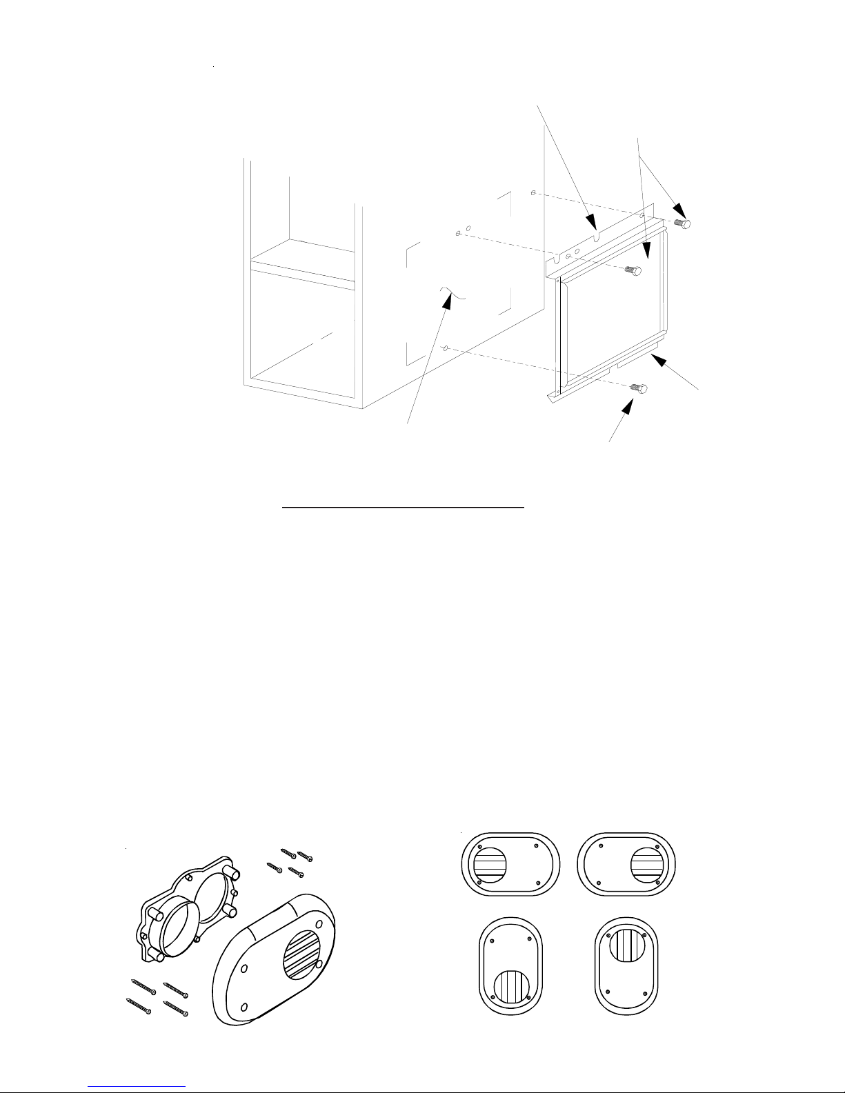
EXTERNAL FILTER RACK (EFR02)
96% Upflow Model Furnaces
FRONT
OF UNIT
BASE
OF UNIT
UNIT SIDE
PANEL
RETURN AIR
CUTOUT AREA
SLOTS IN FILTER
CLEAR SCREWS
ON UNIT
BLOWER DECK
SCREWS
LOWER EDGE
SCREW
FILTER RACK ASSEMBLY
(FACE FILTER OPENING
TOWARDS FRONT
OF UNIT)
SIDE WALL VENT KITS (0170K00000S) (0170K00001S)
Description
0170K00000S
This side wall only vent kit #0170K00000S is to be used with 2” - 3” vent systems. This kit is NOT intended for use with
single pipe (indirect vent) installations.
The vent kit must terminate outside the structure and may be installed with the intake and exhaust pipes located side-byside or with one pipe above the other.
See the section in this manual under "Vent Flue and Combustion Air Pipe Terminations" for more information or consult
the Installation Instructions (IO-635).
0170K00001S
This vent kit is to be used with 2” vent systems. The vent kit must terminate outside the structure and may be installed with
the intake and exhaust pipes located side-by side or with one pipe above the other. This kit is NOT intended for use with
single pipe (indirect vent) installations.
See the section in this manual under "Vent Flue and Combustion Air Pipe Terminations" for more information or consult
the Installation Instructions (IO-805).
Horizontal Installation
12
Vertica l I n s tallatio n
Page 13
ACCESSORIES
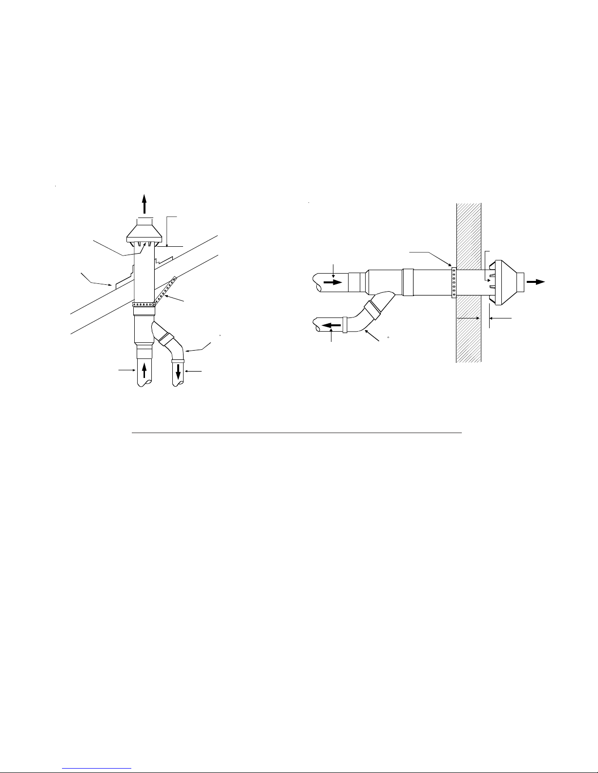
CONCENTRIC VENT CONVERSION KIT
The CVENT-2 (DCVK20) (2") or the CVENT-3 (DCVK-30) (3") is a concentric vent kit approved with furnaces listed in
this manual.
This concentric vent kit allows for vertical or horizontal vent termination. The illustrations give a brief view of the kit and
its application.
See the section in this manual under "Vent Flue and Combustion Air Pipe Terminations" for more information or consult
the Installation and Operating Instructions (IO-619*).
Vent
Maintain 12" (18" for Canada)
minimum clearance above highest
anticipated snow level. Maximum of
Combustion Air
24" above roof.
Roof Boot/Flashing
(Field Supplied)
Support (Field Supplied)
45 Elbow
(Field Supplied)
Vent
Combustion Air
DCVK (Vertical Installation)
AFE18-60A Dual Fuel Accessory
When installing the communicating capable furnace with a
heat pump, the preferred installation would include a communicating thermostat. A communicating thermostat provides control of gas heat and heat pump operation and eliminates the need for a separate dual fuel control. A legacy
dual fuel thermostat could also be used with 24 volt wiring to
control the gas furnace and heat pump. If a communicating
thermostat or legacy dual fuel thermostat are not used, the
AFE18-60A kit must be added to provide control of the equipment. This control is mounted indoors near the furnace and
provides terminals for thermostat, furnace, and heat pump
wiring. The AFE18-60A may be used with or without a separate outdoor thermostat.
CFSB17, 21, 24 Counter Flow Base
The CFSB base must be used when installing a *CVC96
furnace in the vertical position on a combustible floor without a coil under the furnace.
Vent
Combustion Air
Strap
(Field Supplied)
45 Elbow
(Field Supplied)
Combustion Air
Flush to
1" maximum
DCVK (Horizontal Installation)
LPLP03 Low LP Gas Pressure Shut-off Kit
Installation of the LPLP03 kit is recommended on every L.P.
converted furnace to protect the furnace against low L.P.
gas supply pressure. Low L.P. supply pressure can cause
poor combustion and carbon in the heat exchanger. The
LPLP03 kit will open the electrical circuit to the gas valve in
the event of low supply pressure. The kit contains a pressure switch, gas fittings and electrical harness to connect
the switch in series with the gas valve.
LPM-08 LP Conversion Kit
This furnace is factory equipped to operate on Natural Gas
but may be field converted to operate on L.P. gas. To convert a *MVC96 or *CVC96 furnace to operate on L.P. gas,
the LPM-08 conversion kit must be used. The LPM-08 kit
contains a set of 1.25 mm orifices to replace the factory
installed natural gas orifices and a set of springs to convert
the gas valve to L.P. gas.
OT18-60A Outdoor Thermostat
For use in a legacy dual fuel installation to lock-out the heat
pump at a selected temperature.
Vent
13
Page 14
INST ALLATION CONSIDERA TIONS
Safety
Please adhere to the following warnings and cautions when
installing, adjusting, altering, servicing, or operating the furnace.
WARNING
T
O PREVENT PERSONAL INJURY OR DEATH DUE TO IMPROPER INSTALLATION,
ADJUSTMENT, ALTERATI ON, SERV ICE OR MAINTENANCE, R EFER TO THI S
MANUAL.
QUALIFIED INSTALLE R, SERVICE AGENCY OR THE GAS SUPPLIER.
OR ADDITIONAL ASSISTANCE OR INFORMATION, CONSULT A
F
WARNING
HIS PRODUCT CONTAINS OR PRODUCES A CHEMICAL OR CHEMICALS WHICH
T
MAY CAUSE SERI OUS ILLNESS OR DEATH AN D WHICH ARE KNOWN TO THE
S
TATE OF CALIFORNIA TO CAUSE CANCER, BI RTH DEFECTS OR OTHER
REPRODUCTIVE HARM.
WARNING
TO PREVENT POSSIBLE PROPERTY DAMAGE, PERSONAL INJURY OR DEATH
DUE TO ELECTRICAL SHOCK, THE FURNACE MUST BE LOCATED TO PROTECT
THE ELEC TRICA L COMPON ENTS FROM WAT ER.
Charge (ESD) Precautions
NOTE: Discharge body’s static electricity before touching
unit. An electrostatic discharge can adversely affect electrical components.
Use the following precautions during furnace installation and
servicing to protect the integrated control module from damage. By putting the furnace, the control, and the person at
the same electrostatic potential, these steps will help avoid
exposing the integrated control module to electrostatic discharge. This procedure is applicable to both installed and
uninstalled (ungrounded) furnaces.
1. Disconnect all power to the furnace. Do not touch the
integrated control module or any wire connected to the
control prior to discharging your body’s electrostatic
charge to ground.
2. Firmly touch a clean, unpainted, metal surface of the
furnace near the control. Any tools held in a person’s
hand during grounding will be discharged.
3. Service integrated control module or connecting wiring
following the discharge process in Step 2. Use caution
not to recharge your body with static electricity; (i.e., do
not move or shuffle your feet, do not touch ungrounded
objects, etc.). If you come in contact with an ungrounded
object, repeat Step 2 before touching control or wires.
4. Discharge any static electricity from your body to ground
before removing a new control from its container. Follow
Steps 1 through 3 if installing the control on a furnace.
Return any old or new controls to their containers before
touching any ungrounded object.
Product Application
This product is designed for use as a residential home gas
furnace. It is not designed or certified for use in mobile home,
trailer, or recreational vehicle applications.
This furnace can be used in the following non-industrial
commercial applications: Schools, Office buildings, Churches,
Retail stores, Nursing homes, Hotels/motels, Common or
office areas. In such applications, the furnace must be installed
with the
Goodman® Brand and Amana® Brand 90% furnaces are
ETL certified appliances and are appropriate for use with
natural or propane gas. (NOTE: If using propane gas, a propane conversion kit is required).
Dual certification means that the combustion air inlet pipe is
optional and the furnace can be vented as a:
To ensure proper installation, operation and servicing, thoroughly read the installation and service manuals for specifics pertaining to the installation, servicing and application of
this product.
POSSIBLE PROPERTY DAMAGE, PERSONAL IN JURY OR DEATH DUE TO FIRE,
EXPLOSION, SMOKE, S OOT, CONDENSTAION, E LECTRICAL SHOCK OR CARBON
MONOXIDE MAY RESULT FROM IM PROPER INSTALLATION, RE PAIR, OPERATI ON,
OR MAINTENANCE OF THI S PRODUCT.
T
O PREVENT PROPERTY DAMAGE, PERSONAL INJ URY OR DEATH D UE TO FIRE,
DO NOT INSTALL T HIS FURNACE IN A MOBILE HOME, TRAILER, OR RECREATIONAL
VEHICLE.
To ensure proper furnace operation, install, operate, maintain and service the furnace in accordance with the installation, operation and service instructions, all local building
codes and ordinances. In their absence, follow the latest
edition of the National Fuel Gas Code (NFPA 54/ANSI
Z223.1), and/or CAN/CGA B149 Installation Codes, local
plumbing or waste water codes, and other applicable codes.
A copy of the National Fuel Gas Code (NFPA 54/ANSI
Z223.1) can be obtained from any of the following:
installation instructions.
Non-direct vent (single pipe) central forced air furnace
in which combustion air is taken from the installation
area or from air ducted from the outside or,
Direct vent (dual pipe) central forced air furnace in which
all combustion air supplied directly to the furnace burners through a special air intake system outlined in
this manual and the installation instructions.
WARNING
WARNING
American National Standards Institute
1430 Broadway
New York, NY 10018
14
Page 15
INST ALLATION CONSIDERA TIONS
National Fire Protection Association
1 Batterymarch Park
Quincy, MA 02269
The rated heating capacity of the furnace should be greater
than or equal to the total heat loss of the area to be heated.
The total heat loss should be calculated by an approved
method or in accordance with “ASHRAE Guide” or “Manual
J-Load Calculations” published by the Air Conditioning Contractors of America.
Location Requirements and Considerations
WARNING
O PREVENT POSSIBLE EQUI PMENT DAMAGE, PROPERTY DAMAGE, PERSONAL
T
INJURY OR DEATH, THE FO LLOWING BULLET P OINTS MUST BE OBSERVED
WHEN INSTALLING THE UNIT.
Follow the instructions listed below when selecting a furnace location. Refer also to the guidelines provided in the
Combustion and Ventilation Air Requirements section in this
manual or the installation instructions for details.
• Centrally locate the furnace with respect to the proposed or existing air distribution system.
• Ensure the temperature of the return air entering the
furnace is between 55°F and 100°F when the furnace
is heating.
• If the furnace is installed in an application where the
typical operating sound level of a furnace is deemed
objectionable, an optional sound reduction kit is available. Consult your local distributor for more details.
• Provide provisions for venting combustion products
outdoors through a proper venting system. Special
consideration should be given to vent/flue pipe routing
and combustion air intake pipe when applicable.
90% Furnaces: Refer to the Vent/Flue Pipe and Com-
bustion Air Pipe -Termination Locations section in this
manual or the installation instructions for appropriate
termination locations. Also for 90% furnaces, refer to
the Vent/Flue Pipe and Combustion Air Pipe -Termi-
nation Locations section in this manual or the installation instructions to determine if the piping system
from furnace to termination can be accomplished
within the guidelines given. NOTE: The length of flue
and/or combustion air piping can be a limiting factor
in the location of the furnace.
• Locate the 90% furnace so that the condensate can
be piped at a downward slope away from the furnace
to the drain. Do not locate the furnace or its condensate drainage system in any area subject to below
freezing temperatures without proper freeze protection. Refer to the Condensate Drain Lines and Trap
section in this manual or the installation instructions
for further details.
• Set the 90% furnace on a level floor to enable proper
condensate drainage. If the floor becomes wet or damp
at times, place the furnace above the floor on a concrete base sized approximately 1-1/2" larger than the
base of the furnace. Refer to the Horizontal Applica-
tions and Considerations section in this manual or
the installation instructions for leveling of horizontal
furnaces.
• Ensure upflow or horizontal furnaces are not installed
directly on carpeting, or any other combustible material. The only combustible material allowed is wood.
• A special accessory subbase must be used for upright counterflow unit installations over any combustible material (including wood). Refer to subbase instructions for installation details. (NOTE: A subbase
will not be required if an air conditioning coil is located
beneath the furnace between the supply air opening
and the combustible floor.
• Exposure to contaminated combustion air will result
in safety and performance-related problems. Do not
install the furnace where the combustion air is exposed to the following substances:
chlorinated waxes or cleaners
chlorine-based swimming pool chemicals
water softening chemicals
deicing salts or chemicals
carbon tetrachloride
halogen type refrigerants
cleaning solutions (such as perchloroethylene)
printing inks
paint removers
varnishes
hydrochloric acid
cements and glues
antistatic fabric softeners for clothes dryers
and masonry acid washing materials
• Isolate a non-direct furnace from an area contaminated
by any of the above substances. This protects the
non-direct vent furnace from airborne contaminants.
To ensure that the enclosed non-direct vent furnace
has an adequate supply of combustion air, vent from
a nearby uncontaminated room or from outdoors. Refer to the Combustion and Ventilation Air Require-
ments section in this manual or the installation instructions for details.
• If the furnace is used in connection with a cooling
unit, install the furnace upstream or in parallel with
the cooling unit coil. Premature heat exchanger failure will result if the cooling unit coil is placed in the
return air of the furnace.
15
Page 16
INST ALLATION CONSIDERA TIONS
• If the furnace is installed in a residential garage, position the furnace so that the burners and ignition source
are located not less than 18 inches (457 mm) above
the floor. Protect the furnace from physical damage
by vehicles.
• If the furnace is installed horizontally, the furnace access doors must be vertical so that the burners fire
horizontally into the heat exchanger. Do not install
the unit with the access doors on the “up/top” or “down/
bottom” side of the furnace.
Clearances and Accessibility
Installations must adhere to the clearances to combustible
materials to which this furnace has been design certified.
The minimum clearance information for this furnace is provided on the unit’s clearance label. These clearances must
be permanently maintained. Refer to Specification Sheet for
minimum clearances to combustible materials. Clearances
must also accommodate an installation’s gas, electrical,
and drain trap and drain line connections. If the alternate
combustion air intake or vent/flue connections are used on
a 90% furnace, additional clearances must be provided to
accommodate these connections. Refer to Vent Flue Pipe
and Combustion Air Pipe section in this manual or the installation instructions for details. NOTE: In addition to the
required clearances to combustible materials, a minimum
of 24 inches service clearance must be available in front of
the unit.
A furnace installed in a confined space (i.e., a closet or
utility room) must have two ventilation openings with a total
minimum free area of 0.25 square inches per 1,000 BTU/hr
of furnace input rating. One of the ventilation openings must
be within 12 inches of the top; the other opening must be
within 12 inches of the bottom of the confined space. In a
typical construction, the clearance between the door and
door frame is usually adequate to satisfy this ventilation requirement.
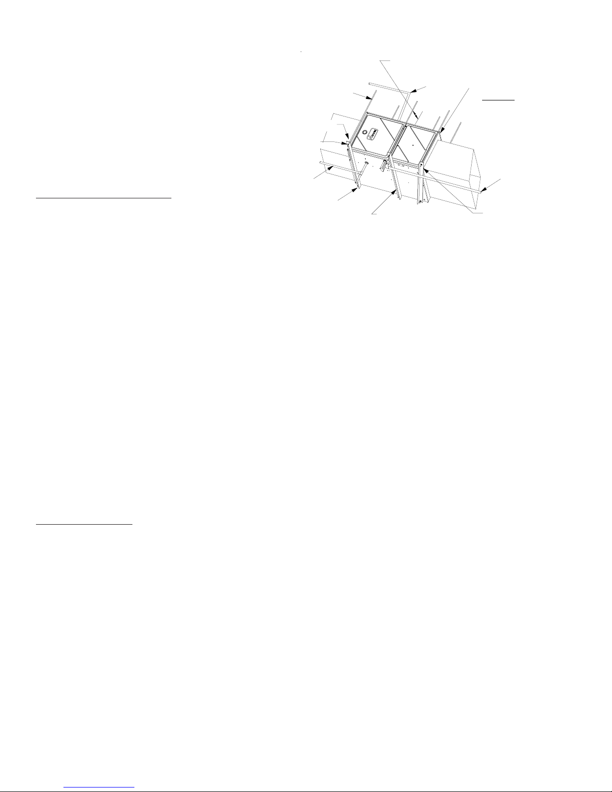
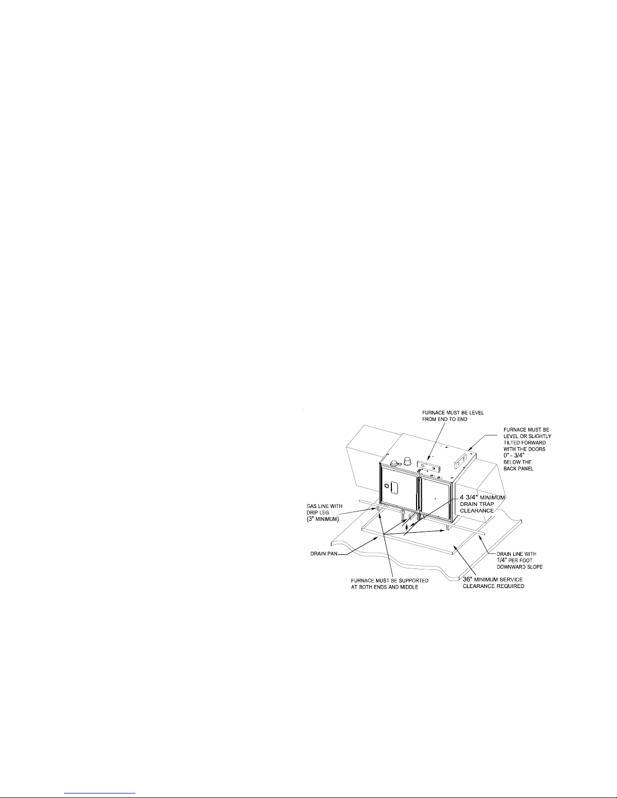
Furnace Suspension
If suspending the furnace from rafters or joist, use 3/8"
threaded rod and 2”x2”x1/8” angle iron as shown in the following figure. If the furnace is installed in a crawl space it
must also be suspended from the floor joist or supported by
a concrete pad. Never install the furnace on the ground or
allow it to be exposed to water. The length of rod will depend
on the application and the clearances necessary.
3/8" DIAMETER
THREADED ROD
HOLD DOWN
NUTS
SUPPORT
NUTS
GAS PIPING
2"X2"X1/8" ANGLE IRON
(3 PLACES)
EXISTING FURNACE REMOVAL
NOTE: When an existing furnace is removed from a venting
system serving other appliances, the venting system may
be too large to properly vent the remaining attached appliances.
The following vent testing procedure is reproduced from the
American National Standard/National Standard of Canada for
Gas-Fired Central Furnaces ANSI Z21.47, latest edition,
CSA-2.3b, latest edition Section 1.23.1.
The following steps shall be followed with each appliance connected to
the venting system placed in operation, while any other appliances
connected to the venting system are not in operation:
a. Seal any unused openings in the venting system;
b. Inspect the venting system for proper size and horizontal pitch,
c. In so far as practical, close all building doors and windows and all
d. Follow the lighting instructions. Place the appliance being in-
e. Test for draft hood equipped spillage at the draft hood relief
f. After it has been determined that each appliance connected to the
g . If improper venting is observed during any of the above tests, the
Corrections must be in accordance with the latest edition of
the National Fuel Gas Code NFPA 54/ANSI Z223.1 and/or
CSA B149 Installation Codes.
PROVIDE 8" MINIMUM CLEARANCE BETWEEN
CENTER ROD AND FURNACE CABINET
TO ALLOW FOR CIRCULATOR BLOWER REMOVAL.
ASSURE FURNACE IS LEVEL FROM
END TO END.
90% FURNACES MAKE SURE
ON
THE UNIT HAS A SLIGHT
FORWARD TILT WITH THE FRONT
OF THE FURNACE 0"-3/4"
BELOW THE BACK OF THE FURNACE.
CONDENSATE
DRAIN
TILT OUTWARD TO ALLOW FOR
DOOR AND CIRCULATOR BLOWER
REMOVAL.
(6 PLACES)
ALTERNATE
GAS PIPING
POSITION AS CLOSE AS POSSIBLE
TO BLOWER DECK TO ALLOW FOR
CIRCULATOR BLOWER REMOVAL.
90% Suspended Furnace Shown
as required by the National Fuel Gas Code, ANSI Z223.1 or the
CSA B149 Installation Codes and these instructions. Determine
that there is no blockage or restriction, leakage, corrosion and other
deficiencies which could cause an unsafe condition;
doors between the space in which the appliance(s) connected to
the venting system are located and other spaces of the building.
Turn on clothes dryers and any appliance not connected to the
venting system. Turn on any exhaust fans, such as range hoods
and bathroom exhausts, so they shall operate at maximum speed.
Do not operate a summer exhaust fan. Close fireplace dampers;
spected in operation. Adjust thermostat so appliance shall operate continuously;
opening after 5 minutes of main burner operation. Use the flame
of a match or candle;
venting system properly vents when tested as outlined above,
return doors, windows, exhaust fans, fireplace dampers and any
other gas burning appliance to their previous conditions of use;
common venting system must be corrected.
16
Page 17
INST ALLATION CONSIDERA TIONS
If resizing is required on any portion of the venting system,
use the appropriate table in Appendix G in the latest edition
of the National Fuel Gas Code ANSI Z223.1 and/or CSA B149
Installation Codes.
Thermostat Requirements
The optional CTK0*** thermostat kit may be used with
ComfortNet™ compatable furnaces (ACVC, AMVC, GCVC,
GMVC models). Refer to System Operation - ComfortNet™
System for details.
NOTE: A single-stage thermostat with only one heating
stage can be used to control a two-stage furnace. The application of a single-stage thermostat does not offer "true"
thermostat driven two-stage operation, but provides a timed
transition from low to high fire. The furnace will run on low
stage for a fixed period of time before stepping up to high
stage to satisfy the thermostat's call for heat. The delay
period prior to stepping up can be set at either 5 or 10 minutes through the DIP switch adjacent to the Heat Off delay
DIP switches on the integrated control module. To use a
single-stage thermostat, turn off power to the furnace, move
the thermostat selection jumper on the integrated contro
module from the "two-stage" position to the "single-stage"
position, turn power back on. Refer to DIP switch charts on
pages 41 & 42.
NOTE: A single-stage thermostat with only one heating stage
may be used to control ComfortNet™ compatible furnaces
(ACVC, AMVC, GCVC, GMVC models). The application of
a single-stage thermostat does not offer “true” thermostatdriven two-stage operation, but provides a timed transition
from low to high fire. The furnace will run on low stage for a
fixed period of time before stepping up to high stage to satisfy the thermostat’s call for heat. The delay period prior to
stepping up can be set at either a fixed 5 minute time delay
or a load based variable time between 1 and 12 minutes
(AUTO mode). If the AUTOmode is selected, the control
averages the cycle times of the previous three cycles and
uses the average to determine the time to transition from
low stage to high stage.
To use a single-stage thermostat, turn off power to the furnace, move the thermostat selection DIP switch to the OFF
position. Set the desired transition time by setting the transition delay DIP switch to the desired ON/OFF position. Turn
power back on. Refer to DIP switch charts on pages 41 &
42.
Dehumidistat Requirements
A dehumidistat can be used in conjunction with the twostage variable speed furnace to lower the humidity in the
conditioned space. The dehumidistat will improve dehumidification of the conditioned air by prompting the furnace to
reduce the speed of the circulator blower during operation in
the cooling mode. To be compatible with these furnaces, a
dehumidistat must operate on 24 VAC and utilize a switch
which opens on humidity rise. Refer to Electrical Connec-
tions - 24 Volt Dehumidistat Wiring section in this manual
or the installation instructions for correct installation procedure.
Thermostat and Dehumidistat Location
In an area having good air circulation, locate the thermostat
and dehumidistat (if applicable) about five feet high on a vibration-free inside wall. Do not install the thermostat or dehumidistat where it may be influenced by any of the following:
• Drafts, or dead spots behind doors, in corners, or un-
• Hot or cold air from registers.
• Radiant heat from the sun.
• Light fixtures or other appliances.
• Radiant heat from a fireplace.
• Concealed hot or cold water pipes, or chimneys.
• Unconditioned areas behind the thermostat and de-
Consult the instructions packaged with the thermostat and
dehumidistat for mounting instructions and further precautions.
COMBUSTION AND VENTILATION AIR
REQUIREMENTS
OSSIBLE PROPERTY DAMAGE, PERSONAL I NJURY OR DEATH MAY OCCUR
P
IF THE FURNACE I S NOT PR OVIDED WITH ENOUGH FRESH AIR FOR PROPER
COMBUSTION AND VENTIL ATION OF F LUE GASES. MOST HOMES REQUI RE
OUTSIDE AIR BE SUPPLIED TO THE FURNACE AREA.
Improved construction and additional insulation in buildings
have reduced heat loss by reducing air infiltration and escape around doors and windows. These changes have helped
in reducing heating/cooling costs but have created a problem supplying combustion and ventilation air for gas fired
and other fuel burning appliances. Appliances that pull air
out of the house (clothes dryers, exhaust fans, fireplaces,
etc.) increase the problem by starving appliances for air.
When the furnace is installed as a direct vent (2-pipe) furnace, no special provisions for air for combustion are required. However, if this furnace is to be installed in the same
space with other gas appliances, such as a water heater,
ensure there is an adequate supply of combustion and ventilation air for the other appliances. Refer to the latest edition of the National Fuel Gas Code NFPA 54/ANSI Z223.1
(Section 9.3), or CAN/CGA B149 Installation Codes (Sections 7.2, 7.3, or 7.4), or applicable provisions of the local
building codes for determining the combustion air requirements for the appliances.
der cabinets.
humidistat, such as an outside wall.
WARNING
17
Page 18
INST ALLATION CONSIDERA TIONS
Most homes will require outside air be supplied to the furnace area by means of ventilation grilles or ducts connecting directly to the outdoors or spaces open to the outdoors
such as attics or crawl spaces.
The following information on air for combustion and ventilation
is reproduced from the National Fuel Gas Code NFPA 54/ANSI
Z223.1 Section 9.3.
9.3* Air for Combustion and Ventilation.
9.3.1 General.
9.3.1.1 Air for combustion, ventilation, and dilution of flue gases for
appliances installed in buildings shall be obtained by application of one
of the methods covered in 9.3.2 through 9.3.6. Where the requirements
of 9.3.2 are not met, outdoor air shall be introduced in accordance with
methods covered in 9.3.3 through 9.3.6.
Exception No. 1: This provision shall not apply to direct vent appliances.
9.3.1.2 Appliances of other than natural draft design and other than
Category 1 vented appliances shall be provided with combustion, ventilation, and dilution air in accordance with the appliance manufacturer’s
instructions.
9.3.1.3 Appliances shall be located so as not to interfere with proper
circulation of combustion, ventilation, and dilution air.
9.3.1.4 Where used, a draft hood or a barometric draft regulator shall be
installed in the same room or enclosure as the appliance served so as to
prevent any difference in pressure between the hood or regulator and the
combustion air supply.
(2) For fan-assisted appliances, calculate using the following equation:
Required Volume
where:
I
other
I
fan
ACH = air change per hour (percent of volume of space exchanged
(3) For purposes of this calculation, an infiltration rate greater than
0.60 ACH shall not be used in the equations in 9.3.2.2(1) and
9.3.2.2(2).
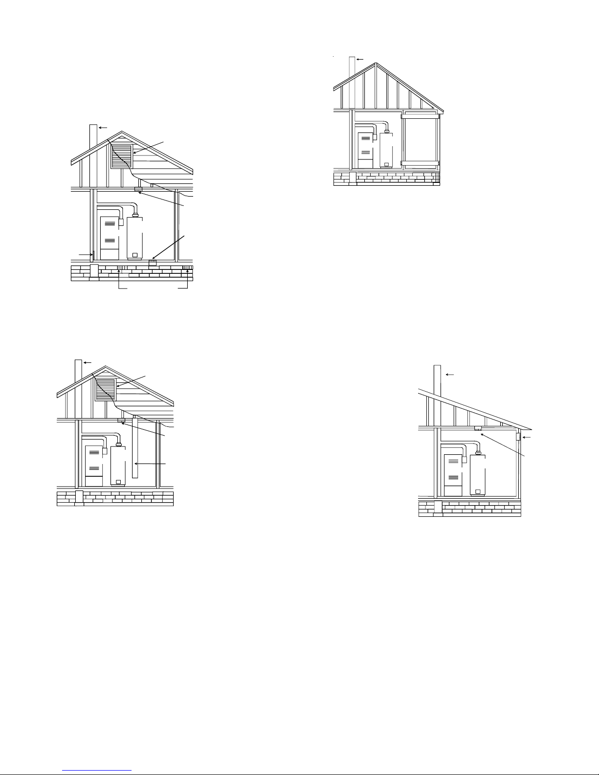
9.3.2.3 Indoor Opening Size and Location. Openings used to connect
indoor spaces shall be sized and located in accordance with the following:
(1)*Combining spaces on the same story. Each opening shall have a
minimum free area of 1 in.
input rating of all appliances in the space but not less than 100 in.
(0.60m2). One opening shall commence within 12 in. (300 mm) of
the top, and one opening shall commence within 12 in. (300 mm) of
the bottom, of the enclosure [see Figure A.9.3.2.3(1)]. The mini-
mum dimension of air openings shall be not less than 3 in. (80 mm).
NOTE: Each opening must have
a free area of not less than one
square inch per 1000 BTU of
the total input rating of all equipment in the enclosure, but not
less than 100 square inches.
3
> ________ _________
fan
15 ft
ACH 1000 Btu/hr
I
fan
()
= all appliances other than fan-assisted input in Btu per
hour
= fan-assisted appliances input in Btu per hour
per hour, expressed as a decimal)
2
/1000Btu/hr (2200 mm2/kW) of the total
Chimney or Gas Vent
2
9.3.1.5 Makeup air requirements for the operation of exhaust fans, kitchen
ventilation systems, clothes dryers, and fireplaces shall be considered in
determining the adequacy of a space to provide combustion air requirements.
9.3.2 Indoor Combustion Air . The required volume of indoor air shall
be determined in accordance with the method in 9.3.2.1 or 9.3.2.2 except that where the air infiltration rate is known to be less than 0.40
ACH, the method in 9.3.2.2 shall be used. The total required volume
shall be the sum of the required volume calculated for all appliances
located within the space. Rooms communicating directly with the space
in which the appliances are installed through openings not furnished
with doors, and through combustion air openings sized and located in
accordance with 9.3.2.3, are considered a part of the required volume.
9.3.2.1* Standard Method. The minimum required volume shall be 50
ft 3 per 1,000/Btu/hour (4.8m3/kW).
9.3.2.2* Known Air Infiltration Rate Method. Where the air infiltration rate of a structure is known, the minimum required volume shall be
determined as follows:
(1) For appliances other than fan-assisted, calculate using the following
equation:
Required Volume
> ________ _________
other
3
21 ft
I
other
ACH 1000 Btu/hr
(
)
Opening
Water
Heater
Furnace
Opening
Figure A.9.2.3.3.(1) All Combustion Air from Adjacent
Indoor Spaces through Indoor Combustion Air Openings.
(2) Combining spaces in different stories. The volumes of spaces in
different stories shall be considered as communicating spaces where
such spaces are connected by one or more openings in doors or
floors having a total minimum free area of 2 in.2/1000 Btu/hr (4400
mm2/kW) of total input rating of all appliances.
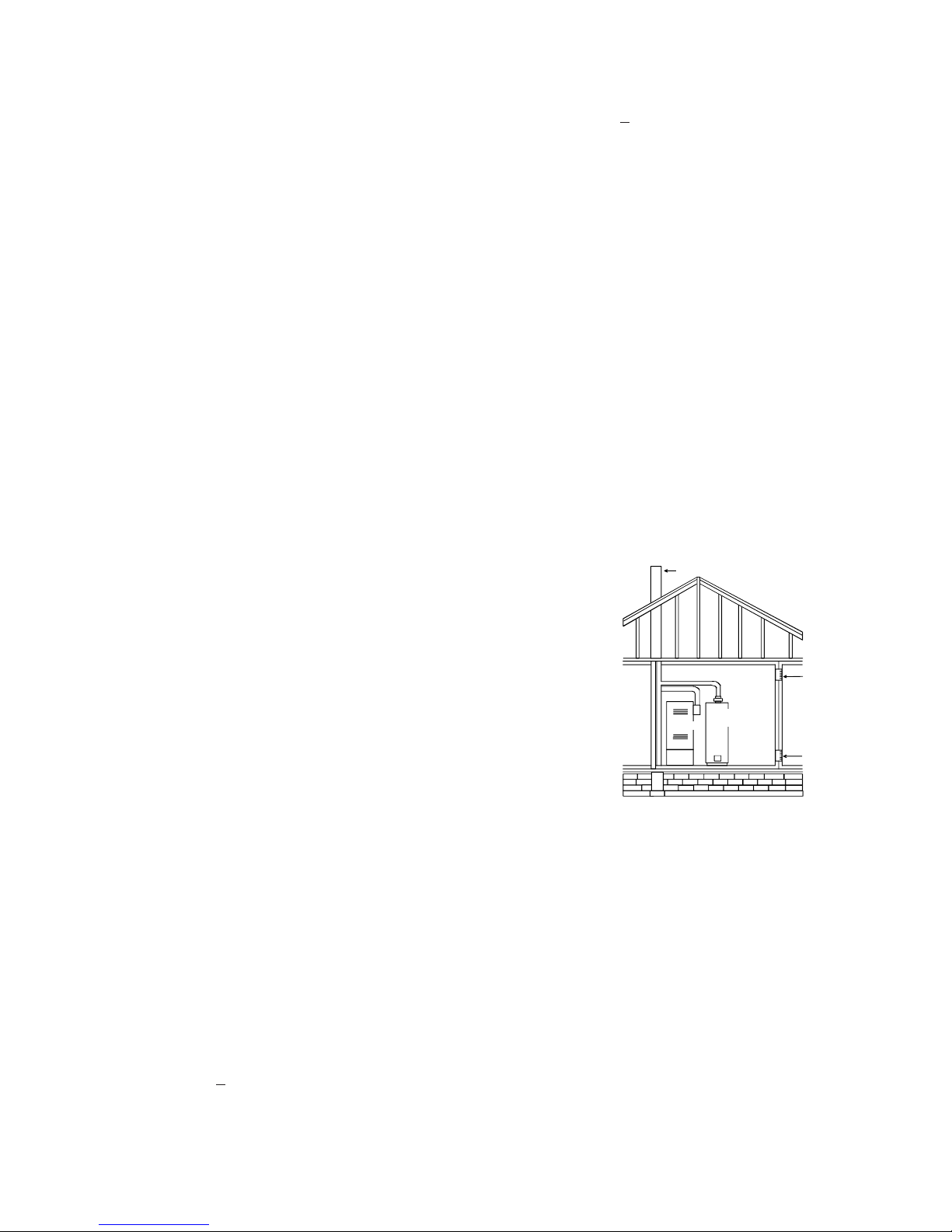
9.3.3 Outdoor Combustion Air. Outdoor combustion air shall be provided through opening(s) to the outdoors in accordance with the methods in 9.3.3.1 or 9.3.3.2. The minimum dimension of air openings shall
not be less than 3 in. (80 mm).
9.3.3.1 Two Permanent Openings Method. Two permanent openings, one commencing within 12 in. (300 mm) of the top and one commencing within 12 in. (300 mm) of the bottom, of the enclosure shall be
provided. The openings shall communicate directly, or by ducts, with
the outdoors or spaces that freely communicate with the outdoors, as
follows:
18
Page 19
INST ALLATION CONSIDERA TIONS
A
(1)*Where directly communicating with the outdoors or where commu-
nicating to the outdoors through vertical ducts, each opening shall
have a minimum free area of 1 in.
total input rating of all appliances in the enclosure. [See Figure
A.9.3.3.1(1)(a) and Figure A.9.3.3.1(1)(b).]
Chimney or Gas Vent
Water
Heater
Furnace
lternate
air inlet
Ventilation louvers for
unheated crawl space
Figure A.9.3.3.1(1)(a) All Combustion Air Fr om Outdoors -
Inlet Air from Ventilated Crawl Space and Outlet Air
to Ventilated Attic.
2
/4000 Btu/hr (550 min2/kW) of
Ventilation louvers
(each end of attic)
NOTE: The inlet and outlet a ir
openings must each have a free
area of not less than one square
inch per 4000 BTU of the
total input rating of all equipment
in the enclosure.
Outlet Air
Inlet Air
9.3.3.2* One Permanent Opening Method. One permanent openings, commencing within 12 in. (300 mm) of the top of the enclosure,
shall be provided. The appliance shall have clearances of at least 1 in. (25
mm) from the sides and back and 6 in. (150 mm) from the front of the
appliance. The opening shall directly communicate with the outdoors or
shall communicate through a vertical or horizontal duct to the outdoors
or spaces that freely communicate with the outdoors (see Figure
A.9.3.3.2) and shall have a minimum free area of the following:
(1) 1 in.
appliances located in the enclosure, and
(2) Not less than the sum of the areas of all vent connectors in the
space.
Chimney or Gas Vent
NOTE: The air duct openings
must have a free a r ea o f not
less than one square inch per
2000 BTU of the total input
rating of all equipment in the
enclosure*.
Furnace
Water
Heater
Outlet air duct
Inlet air duct
Figure A.9.3.3.1(2) All Combustion Air From Outdoors
through Horizontal Ducts.
2
/3000 Btu/hr (700 mm2 per kW) of the total input rating of all
Chimney or Gas Vent
Ventilation louvers
(each end of attic)
NOTE: The inlet and outlet air
openings must each have a free
area of not less than one square
inch per 4000 BTU of the
total input rating of all equipmen t
in the enclosure.
Outlet Air
Water
Heater
Furnace
Inlet air duct
[ends 1 ft (300 mm)
above floor]
Figure A.9.3.3.1(1)(b) All Combustion Air
From Outdoors through Ventilated Attic.
(2)*Where communicating with the outdoors through horizontal ducts,
each opening shall have a minimum free area of 1 in.2/2000 Btu/hr
(1100 min2/kW) of total input rating of all appliances in the enclosure. [See Figure A.9.3.3.1(2).]
NOTE: The single opening must have
a free area of not less than one
square inch per 30 00 BT U o f
the total in p ut rat i ng of all equipment in th e enclosure, but not less than
the sum of the areas of all vent
connecto rs in the confined space.
Chimney or Gas Vent
Water
Heater
Furnace
Opening
Alternate
Opening
Location
Figure A.9.3.3.2 All Combustion Air
From Outdoors through Single Combustion Air Opening.
9.3.4 Combination Indoor and Outdoor Combustion Air. The use of
a combination of indoor and outdoor combustion air shall be in accordance with (1) through (3) (see example calculation in Annex J]:
(1) Indoor Openings: Where used, openings connecting the interior
spaces shall comply with 9.3.2.3.
(2) Outdoor Opening(s) Location. Outdoor opening(s) shall be located
in accordance with 9.3.3.
(3) Outdoor Opening(s) Size. The outdoor opening(s) size shall be
calculated in accordance with the following:
(a) The ratio of the interior spaces shall be the available volume of
all communicating spaces divided by the required volume.
(b) The outdoor size reduction factor shall be 1 minus the ratio of
interior spaces.
19
Page 20
INST ALLATION CONSIDERA TIONS
(c) The minimum size of outdoor opening(s) shall be the full size
of outdoor opening(s) calculated in accordance with 9.3.3,
multiplied by the reduction factor. The minimum dimension
of air openings shall not be less than 3 in. (80 mm).
9.3.8.4 Ducts shall not serve both upper and lower combustion air
openings where both such openings are used. The separation between
ducts servicing upper and lower combustion air openings shall be maintained to the source of combustion air.
9.3.5 Engineered Installations. Engineered combustion air installations shall provide an adequate supply of combustion, ventilation, and
dilution air and shall be approved by the authority having jurisdiction.
9.3.6 Mechanical Combustion Air Supply. Where all combustion air
is provided by a mechanical air supply system, the combustion air shall
be supplied form outdoors at the minimum rate of 0.35 ft3/min per 1000
Btu/hr (0.034 m
space.
9.3.6.1 Where exhaust fans are installed, additional air shall be provided
to replace the exhausted air.
9.3.6.2 Each of the appliances served shall be interlocked to the mechanical air supply system to prevent main burner operation where the
mechanical air supply system is not in operation.
9.3.6.3 Where combustion air is provided by the building’ s mechanical
ventilation system, the system shall provide the specified combustion
air rate in addition to the required ventilation air.
9.3.7 Louvers, Grilles, and Screens.
9.3.7.1 Louvers and Grilles. The required size of openings for com-
bustion, ventilation, and dilution air shall be based on the net free area of
each opening. Where the free area through a design of louver or grille or
screen is known, it shall be used in calculating the size opening required
to provide the free area specified. Where the louver and grille design and
free area are not known, it shall be assumed that wood louvers will have
25 percent free area, and metal louvers and grilles will have 75 percent
free area. Nonmotorized louvers and grilles shall be fixed in the open
position.
3
/min per kW) for all appliances located within the
9.3.8.5 Ducts shall not be screened where terminating in an attic space.
9.3.8.6 Horizontal upper combustion air ducts shall not slope down-
ward toward the source of combustion air.
9.3.8.7 The remaining space surrounding a chimney liner, gas vent, special gas vent, or plastic piping installed within a masonry, metal, or
factory built chimney shall not be used to supply combustion air.
Exception: Direct vent appliances designed for installation in a solid
fuel-burning fireplace where installed in accordance with the
manufacture’s installation instructions.
9.3.8.8 Combustion air intake openings located on the exterior of the
building shall have the lowest side of the combustion air intake openings
located at least 12 in. (300 mm) vertically from the adjoining grade level.
Horizontal Applications and Considerations
Horizontal applications, in particular, may dictate many of
the installation’s specifics such as airflow direction, ductwork connections, flue and/or combustion air pipe connections, etc. The basic application of this furnace as a horizontal furnace differs only slightly from an upright installation. When installing a furnace horizontally, additional consideration must be given to the following:
9.3.7.2 Minimum Scree Mesh Size. Screens shall not be smaller than
1/4 in. mesh.
9.3.7.3 Motorized Louvers. Motorized louvers shall be interlocked
with the appliance so they are proven in the full open position prior to
main burner ignition and during main burner operation. Means shall be
provided to prevent the main burner form igniting should the louver fail
to open during burner startup and to shut down the main burner if the
louvers close during burner operation.
9.3.8 Combustion Air Ducts. Combustion air ducts shall comply with
9.3.8.1 through 9.3.8.8.
9.3.8.1 Ducts shall be constructed of galvanized steel or a material having equivalent corrosion resistance, strength, and rigidity.
Exception: Within dwellings units, unobstructed stud and joist spaces
shall not be prohibited from conveying combustion air, provided that not
more than one fireblock is removed.
9.3.8.2 Ducts shall terminate in an unobstructed space, allowing free
movement of combustion air to the appliances.
9.3.8.3 Ducts shall serve a single space.
90% Horizontal Furnace Shown
20
Page 21
INST ALLATION CONSIDERA TIONS
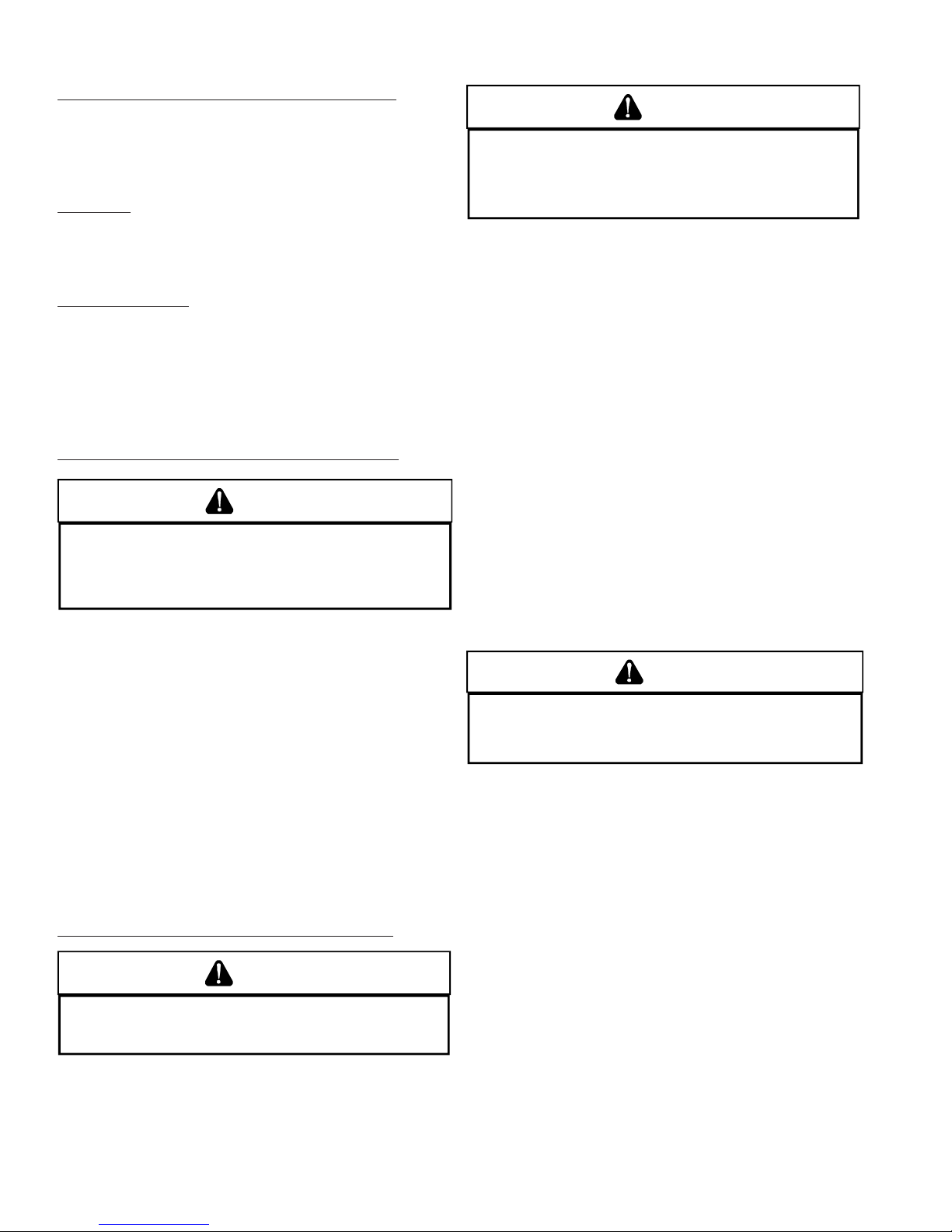
Installation Positions
*MVC96 models may be installed up flow or horizontally
with left or right side down. *CVC96 models may be installed
down flow or horizontally with left or right side down. Do not
install any furnace on its back.
Horizontal Installations
1. Horizontal installations require 5.5" under the furnace
to accommodate the drain trap.
2. Horizontal furnaces must be installed with ¾” slope from
back to front to permit condensate flow towards the
front of the furnace.
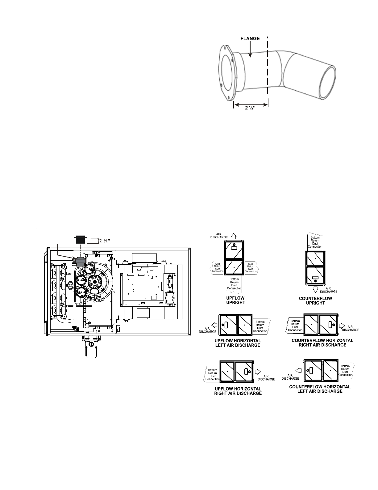
When installing a *MVM97 horizontally with the left side
down, there are two options for connecting the vent pipe to
the furnace.
1. Venting may be connected to the furnace vent pipe fitting on the original top (now the end) of the furnace
2. The internal vent pipe and elbow may be removed from
the furnace to permit the vent to exit the top (original
side) of the furnace. If this option is used, an RF000142
Vent-Drain coupling must be used to keep condensate
from collecting in the inducer assembly.
Refer to the following instructions and illustration.
1. Remove screws from vent flange.
2. Remove internal elbow and vent pipe.
3. Cut pipe 2 1/2” from flange.
4. Remove cabinet plug adjacent to inducer outlet and install an original cabinet vent hole.
5. Install RF000142 coupling on inducer outlet.
6. Install flanged vent section removed in step 2 & secure
with clamps.
7. Secure flange to cabinet using screws removed in step
1.
E
R
E
H
T
U
C
Vent/Flue Pipe Cuts
R 000142F
Insert flange. Cut 2 ½” long.
90% Furnace Recommended Installation Positions
NOTE: Alternate "vertical" piping connections can not be
used when an upflow 90% furnace is installed with supply
air discharging to the right or when a counterflow furnace is
installed with supply discharging to the left. In this case,
use the standard flue and combustion air piping connections
21
Page 22
INST ALLATION CONSIDERA TIONS
Alternate Electrical and Gas Line Connections
The furnaces have provisions allowing for electrical and gas
line connections through either side panel. In horizontal applications the connections can be made either through the
“top” or “bottom” of the furnace.
Drain Pan
A drain pan must be provided if the furnace is installed above
a conditioned area. The drain pan must cover the entire area
under the furnace (and air conditioning coil if applicable).
Freeze Protection
If the drain trap and drain line will be exposed to temperatures near or below freezing, adequate measures must be
taken to prevent condensate from freezing. NOTE: The use
of insulation and/or heat tape is recommended. Failure to
provide proper condensate drainage can result in property
damage.
Propane Gas and/or High Altitude Installations
WARNING
P
OSSIBLE PRO PERTY DA MAGE, PERSO NAL IN JURY OR DEATH MAY OCCUR IF
THE CORRECT CONV ERSI ON KITS ARE NOT IN STALLE D.
MUST BE APPLIE D TO I NSURE SAFE AN D PROPER FURNAC E OPERAT ION.
CONVERSIONS MUS T BE PERFORMED BY A QUALIF IE D INSTA LLER OR SERV ICE
AGENCY.
THE APPROPRIATE KI TS
ALL
WARNING
UPON COMPLETION OF THE FURNA CE INSTALLATIO N, CAREFULLY I NSPECT THE
ENTIRE FLUE SYSTEM BO TH INSIDE AND OUTSIDE THE FURNACE TO ASS URE IT
IS PROPERLY SEALED.
PERSONAL INJURY OR DE ATH DUE TO EXPOS URE TO FLUE PRODUCTS,
INCLUDING CARBON MONOXIDE.
LEAKS IN THE FLUE SYSTEM CAN RESULT IN SERIOUS
A condensing gas furnace achieves its high level of efficiency
by extracting almost all of the heat from the products of
combustion and cooling them to the point where condensation takes place. Because of the relatively low flue gas temperature and water condensation requirements, PVC pipe is
used as venting material.
This furnace must not be connected to Type B, BW, or L
vent or vent connector, and must not be vented into any
portion of a factory built or masonry chimney except when
used as a pathway for PVC as described later in this section. Never common vent this appliance with another appliance or use a vent which is used by a solid fuel appliance.
It is the responsibility of the installer to follow the manufacturers’ recommendations and to verify that all vent/flue piping and connectors are compatible with furnace flue products. Additionally, it is the responsibility of the installer to
ensure that all piping and connections possess adequate
structural integrity and support to prevent flue pipe separation, shifting, or sagging during furnace operation.
This furnace is shipped from the factory configured for natural gas at standard altitude. Propane gas installations require an orifice change to compensate for the energy content difference between natural and propane gas.
High altitude installations may require both a pressure switch
and an orifice change. These changes are necessary to compensate for the natural reduction in the density of both the
gas fuel and the combustion air at higher altitude.
Refer to the Accessories Charts in this manual or product
Specification Sheet for a tabular listing of appropriate
manufacturer’s kits for propane gas and/or high altitude installations. The indicated kits must be used to insure safe
and proper furnace operation. All conversions must be performed by a qualified installer, or service agency.
VENT/FLUE PIPE AND COMBUSTION AIR PIPE
WARNING
F
AILURE TO FOLLOW THESE INSTRUCTIONS CAN RESULT IN BODILY INJURY OR
DEATH.
CAREFULLY READ AND FOLLOW ALL INSTRUCTIONS GIVEN IN THIS
SECTION.
Materials and Joining Methods
WARNING
T
O AVOID BODILY INJURY, FIRE OR EXPLOSION, SOLVENT CEMENTS MUST BE
KEPT AWAY FROM ALL IGNITION SOURCES (I.E., SPARKS, OPEN FLAMES, AND
EXCESSIVE HEAT) AS THEY ARE COMBUSTIBLE LIQUIDS.
CEMENT VAPORS OR CONTACT WITH SKIN AND/ OR EYES.
A
VOID BREATHING
Precautions should be taken to prevent condensate from
freezing inside the vent/flue pipe and/or at the vent/flue pipe
termination. It is our recommendation that all vent/flue piping
exposed to temperatures below 35°F for extended periods
of time should be insulated with 1/2” thick closed cell foam.
Also all vent/flue piping exposed outdoors in excess of the
terminations shown in this manual (or in unheated areas)
should be insulated with 1/2” thick closed cell foam. Inspect
piping for leaks prior to installing insulation.
The following bullets and diagram describe the restrictions
concerning the appropriate location of vent/flue pipe and combustion air intake pipe (when applicable) terminations. Refer to the installation instructions for specific details on termination construction.
• All terminations must be located at least 12 inches
above ground level or the anticipated snow level.
• Vent terminations must terminate at least 3 feet above
any forced air inlet located within 10 feet.
22
Page 23
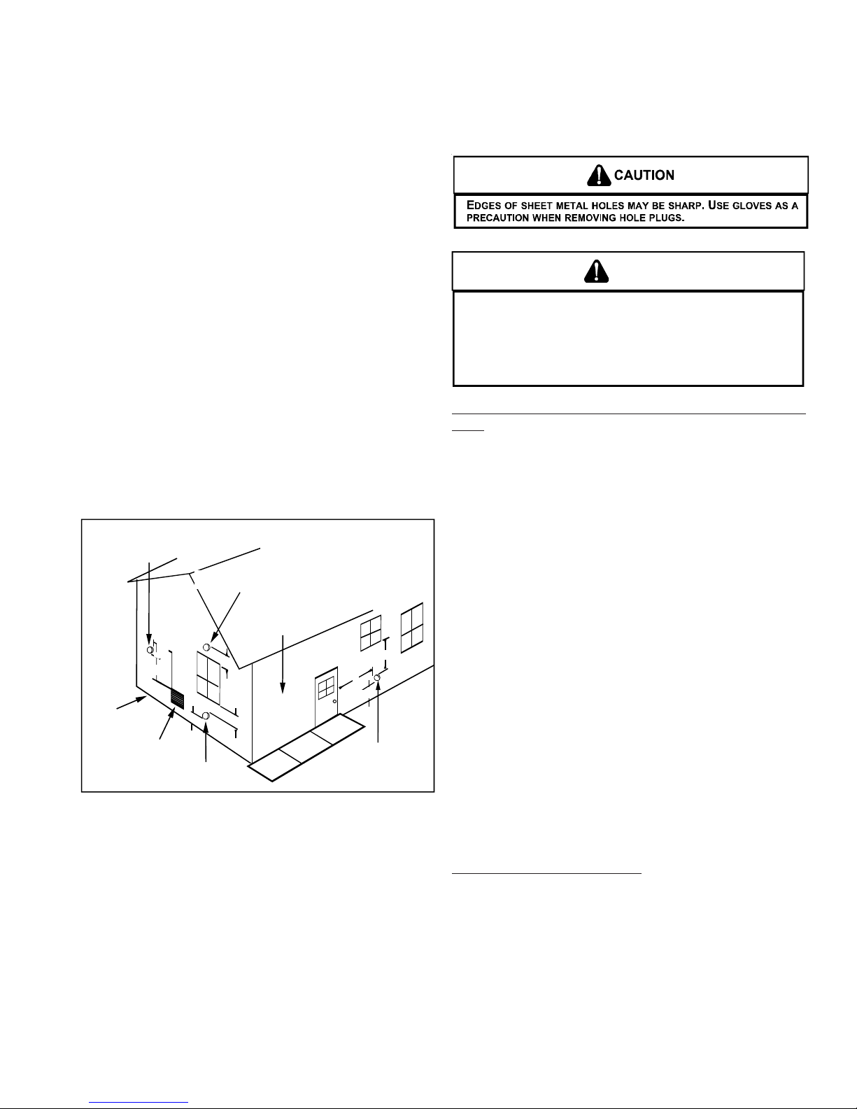
INST ALLATION CONSIDERA TIONS
NOTE: This provision does not apply to the combus-
tion air intake termination of a direct vent application.
• The vent termination of a non-direct vent application
must terminate at least 4 feet below, 4 feet horizontally from, or 1 foot above any door, window, or gravity
air inlet into any building.
• The vent termination of a direct vent application must
terminate at least 12 inches from any opening through
which flue gases may enter a building (door, window,
or gravity air inlet).
• The vent termination of vent pipe run vertically through
a roof must terminate at least 12 inches above the
roof line (or the anticipated snow level) and be at least
12 inches from any vertical wall (including any anticipated snow build up).
• A vent termination shall not terminate over public walkways or over an area where condensate or vapor could
create a nuisance or hazard or could be detrimental
to the operation of regulators, relief valves, or other
equipment.
• The combustion air intake termination of a direct vent
application should not terminate in an area which is
frequently dusty or dirty.
NOTE: In Canada, CAN B149.1 Fuel Gas Code takes precedence over the preceding termination restrictions.
OTHER THAN
COMBUSTION AIR
TERMINATION INTAKE
NON-DIRECT VENT
VENT/FLUE TERMINATION
NO TERMINATIONS
ABOVE WALKWAY
3"
GRADE OR HIGHEST
ANTICIPATED
SNOW LEVEL
FORCED AIR
INLET
10'
12"
12"
DIRECT VENT
VENT/FLUE TERMINATION
12"
VENT/FLUE TERMINATION
4'
4'
12"
NON-DIRECT VENT
90% Furnace Vent Termination Clearances
Direct Vent Installations
On upflow units secure the combustion air intake pipe directly to the air intake coupling. On counterflow units secure the combustion air intake pipe to the air intake coupling using the rubber coupling and worm gear hose clamps
provided with the unit. The counterflow rubber coupling allows service removal of air intake piping internal to the furnace blower compartment. The combustion air intake pipe
can also be secured directly to the counterflow unit air intake pipe coupling.
Non-Direct Vent Installations
A minimum of one 90° elbow must be installed on the combustion air intake “coupling” to guard against inadvertent
blockage.
HE RUBBER ELBOW IS NOT DESIGNED TO SUPPORAT A LOAD. WHEN THE
T
RUBBER ELBOW IS MOUNTED EXTERNALLY TO THE FURNACE CABINET,
EXTREME CARE MUST BE TAKEN TO ADEQUATELY SUPPORT FIELD-SUPPLI ED
VENT/FLUE PIPING, AS DAMAGE CAN RESULT IN LEAKS CAUSING BODILY
INJURY OR DEATH DUE TO EXPOSURE TO FLUE GASES, INCLUDING CARBON
MONOXIDE.
Vent/Flue Pipe Lengths (Non-Direct Vent) and Diameters
Refer to the following table for applicable length, elbows,
and pipe diameter for construction of the vent/flue pipe system of a non-direct vent installation. In addition to the vent/
flue pipe, a single 90° elbow must be secured to the combustion air intake to prevent inadvertent blockage. The tee
or elbows used in the vent/flue termination must be included
when determining the number of elbows in the piping system.
Vent/Flue and Combustion Air Pipe Lengths and Diameters
Refer to the following table for applicable length, elbows,
and pipe diameter for construction of the vent/flue and combustion air intake pipe systems of a non-direct vent (single
pipe) installation. The number of elbows tabulated represents the number of elbows and/or tees in each (Vent/Flue
& Combustion Air Intake) pipe. Elbows and/or tees used in
the terminations must be included when determining the number of elbows in the piping systems.
If the combustion air intake pipe is to be installed above a
finished ceiling or other area where dripping of condensate
will be objectionable, insulation of the combustion air pipe
may be required. Use 1/2” thick closed cell foam insulation
such as Armaflex or Insultube where required.
Vent/Flue Pipe Terminations
The vent/flue pipe may terminate vertically, as through a roof,
or horizontally, as through an outside wall.
Vertical vent/flue pipe termination should be as shown in the
following figures. Refer to Vent/Flue Pipe and Combustion
Air Pipe - Termination Locations section in this manual or
the installation instructions for details concerning location
restrictions. The penetration of the vent through the roof must
be sealed tight with proper flashing such as is used with a
plastic plumbing vent.
WARNING
23
Page 24
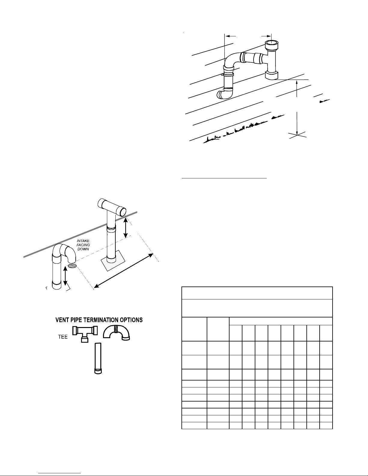
INST ALLATION CONSIDERA TIONS
Horizontal vent/flue pipe terminations should be as shown in
the following figure. Refer to Vent/Flue Pipe and Combus-
tion Air Pipe - Termination Locations section in this manual
or the installation instructions for details concerning location restrictions. A 2 3/8" diameter wall penetration is required for 2" diameter pipe while a 3 1/2" diameter hole is
required for 3" diameter pipe. To secure the pipe passing
through the wall and prohibit damage to piping connections,
a coupling should be installed on either side of the wall and
solvent cemented to a length of pipe connecting the two
couplings. The length of pipe should be the wall thickness
plus the depth of the socket fittings to be installed on the
inside and outside of the wall. The wall penetration should
be sealed with silicone caulking material.
In a basement installation, the vent/flue pipe can be run between joist spaces. If the vent pipe must go below a joist
and then up into the last joist space to penetrate the header,
two 45° elbows should be used to reach the header rather
than two 90° elbows.
NOTE: Terminate both pipes in the same pressure zone
(same side of roof, no major obstacle between pipes, etc).
TEE (OPTIONAL)
COMBUSTION AIR INTAKE
(OPTIONAL)
*Not required for
single pipe installation
E
N
I
L
F
O
O
R
INTAKE
SCREEN
OPTIONAL
12” MIN TO ROOF OR HIGHEST
ANTICIPATED SNOW LEVEL
6
9
12” MIN
HEIGHT DIFFERENCE
BETWEEN
INT AKE AND VENT
”
3
-
.
X
A
M
”
.
N
I
M
90% Furnace Horizontal Termination (Single Pipe)
Direct Vent (Dual Pipe) Piping
Direct vent installations require both a combustion air intake and a vent/flue pipe. The pipes may be run horizontally
and exit through the side of the building or run vertically and
exit through the roof of the building. The pipes may be run
through an existing unused chimney; however, they must
extend a minimum of 12 inches above the top of the chimney. The space between the pipes and the chimney must
be closed with a weather tight, corrosion resistant flashing.
Both the combustion air intake and a vent/flue pipe terminations must be in the same atmospheric pressure zone. Refer to Vent/Flue and Combustion Air Pipe - Termination Lo-
cations or Concentric Vent Termination section in this manual
or the installation instructions for specific details on termination construction.
*MVC9 6/*CVC 9 6 Direct Vent (2 - Pipe) and N on-Direct Vent (1- Pip e)
Unit Input
(Btu)
12" MINIMUM
VENT/FLUE TEE
90° ELBOW TURNED
12" MINIMUM ABOVE
HIGHEST ANTICIPATED
SNOW LEVEL
OR
DOWN
Above Highest Anticipated Snow Level
Maximum Allowable Length of Vent/Flue Pipe
& Comb u stion Air Pipe (ft )
Pipe Size
(4)
(in .)
12345678
Number of Elbows
(1) (2)
(3) (5)
(6)
ELBOWS
STRAIGHT
24
40,000
60,000
80,000 "B" 2 or 2 1/2 75 70 65 60 55 50 45 40
80,000 "B" 3 200 193 186 179 172 165 158 151
80,000 "C" 2 or 2 1/2 25 20 15 10 5 N/A N /A N/A
80,000 "C" 3 200 193 186 179 172 165 158 151
100,000 2 or 2 1/2 25 20 15 10 5 N/A N /A N /A
100,000 3 200 193 186 179 172 165 158 151
120,000 2 or 2 1/2 45 40 35 30 25 20 15 10
120,000 3 95 90 85 80 75 70 65 60
2
or 2 1/2
2
or 2 1/2
120 115 110 105 100 95 90 85
95 90 85 80 75 70 65 60
Page 25

INST ALLATION CONSIDERA TIONS
1) Maximum allowable limits listed on individual lengths for inlet and flue
and NOT a combination.
2) Minimum requirement for each vent pipe is five (5) feet in length and
one elbow/tee.
3) Tee used in the vent/flue termination must be included when determining the number of elbows in the piping system.
4) 2 1/2” or 3” diameter pipe can be used in place of 2” diameter pipe.
5) Increased Clearance Configurations using (2) 45 deg. Long Sweep
elbows should be considered equivalent to one 90 deg. elbow.
6) One 90° elbow should be secured to the combustion air intake connection.
Vent/Flue and Combustion Air Pipe Terminations
VENT/FLUE AND COMBUSTION AIR PIPE TERMINATIONS
The vent/flue and combustion air pipes may terminate vertically, as through a roof, or horizontally, as through an outside wall.
Vertical pipe terminations should be as shown in the following figure. Refer to Section IX, Vent/Flue Pipe and Com-
bustion Pipe - Termination Locations for details concerning
location restrictions. The penetrations through the roof must
be sealed tight with proper flashing such as is used with a
plastic plumbing vent.
Horizontal terminations should be as shown in the following
figure. Refer to Vent/Flue Pipe and Combustion Pipe - Ter-
mination Location section in this manual or the installation
instructions for location restrictions. A 2 3/8" diameter wall
penetration is required for 2" diameter pipe while a 3 1/2"
diameter hole is required for 3" diameter pipe. To secure the
pipe passing through the wall and prohibit damage to piping
connections, a coupling should be installed on either side of
the wall and solvent cemented to a pipe connecting the two
couplings. The pipe length should be the wall thickness
plus the depth of the socket fittings to be installed on the
inside and outside of the wall. The wall penetration should
be sealed with silicone caulking material.
90% Alternate Horizontal Vent Termination (Dual Pipe)
Vent & Combustion Air Intake Measurements for Standard Horizontal Terminations (Dual Pipe)
Center to center = 10” min / 24” max.
Vertical separation: 0” - 24”
Vent termination from wall = 8” min / 12” max.
Combustion air intake from wall = 6” max.
Vent and intake clearance to ground
90°
ELBOWS
3” - 24”
AIR
INTAKE
SCREEN
(OPTIONAL)
12" MIN. ABOVE
HIGHEST ANTICIPATED
SNOW LEVEL
10”- 24”
6” MAX
4” MIN
90º OR 45°
ELBOW
SCREEN
(OPTIONAL)
12" MIN. TO GRADE OR
HIGHEST ANTICIPATED
SNOW L EVEL
Standard Horizontal Terminiations (Dual Pipe)
or anticipated snow level = 12” min.
25
Page 26

INST ALLATION CONSIDERA TIONS
90°
ELBOWS
3”-24” BETWEEN PIPES
AIR
INTAKE
SCREEN
(OPTIONAL)
12" MIN . AB OVE
HIGHEST ANTICIPA TED
SNOW LEVEL
Combustion Air Intake may also be snorkeled to obtain 12”
min ground clearance.
90% Furnace Alternate Vent Termination
Above Anticipated Snow Level (Dual Pipe)
In a basement installation, the pipes may be run between
the joist spaces. If the pipes must go below the joist and
then up into the last joist space to penetrate the header, two
45° elbows should be used to reach the header rather than
two 90° elbows.
VENT/INTAKE TERMINATIONS FOR INSTALLATION OF MULTIPLE
DIRECT VENT FURNACES
If more than one direct vent furnace is to be installed vertically through a common roof top, maintain the same minimum clearances between the exhaust vent and air intake
terminations of adjacent units as with the exhaust vent and
air intake terminations of a single unit.
If more than one direct vent furnace is to be installed horizontally through a common side wall, maintain the clearances as in the following figure. Always terminate all exhaust vent outlets at the same elevation and always terminate all air intakes at the same elevation.
Condensate Drain Lines and Drain Trap
A condensing gas furnace achieves its high level of efficiency by
extracting heat from the products of combustion to the point
where condensation takes place. The condensate must be
collected in the furnace drain trap and routed to an appropriate drain location in compliance with local and national codes.
Follow the bullets listed below when installing the drain system.
Refer to the following sections for specific details concerning
furnace drain trap installation and drain hose hook ups.
• The drain trap supplied with the furnace must be used.
• The drain trap must be primed at time of installation.
• The drain line between furnace and drain location must
meet local and nation codes.
• The drain line between furnace and drain location must
maintain a 1/4 inch per foot downward slope toward the
drain.
• Do not trap the drain line in any other location than at the
drain trap supplied with the furnace.
• If the drain line is routed through an area which may see
temperatures near or below freezing, precautions must
be taken to prevent condensate from freezing within the
drain line.
• If an air conditioning coil is installed with the furnace, a
common drain may be used. An open tee must be installed in the drain line, near the cooling coil, to relieve
positive air pressure from the coil’s plenum. This is necessary to prohibit any interference with the function of the
furnace’s drain trap.
WARNING
N UPRIGHT UPFLOW INS TALLATIONS, THE DRA IN TRAP MUST BE MOUNTED ON
I
THE OPPOSITE S IDE OF THE UNIT FROM THE JUNC TION BOX .
REDUCE THE RIS K OF WATER REACH ING THE JUNCTION BOX I N THE EVENT OF
trap.
A BLOCKED DRAIN CONDITION.
CAN RESULT I N POSSIBLE PRO PERTY DAMAGE, PERS ONAL INJURY, OR DEATH
DUE TO EL ECT RI CAL S HOC K.
AILURE TO FOLLOW THESE I NSTRUCTIONS
F
HIS WILL
T
3” - 24”
12” MIN SEPARATION
3” MIN
OPTIONAL
INTAKE
SCREENS
12” MIN TO GRADE OR HIGHEST
ANTICIPATED SNOW LEVEL
90% Furance Horizontal Venting of Multiple Units
(Dual Pipe)
26
GAS SUPPLY AND PIPING
The furnace rating plate includes the approved furnace gas
input rating and gas types. The furnace must be equipped to
operate on the type of gas applied. This includes any conversion kits required for alternate fuels and/or high altitude.
CAUTION
O PREVENT UNRELI ABLE OPE RATION OR EQUIP MENT DAMAGE, THE INLE T
T
GAS SUPPLY PRESSURE MUST BE AS SPECIFIED ON THE UNIT RATING PLATE
WITH ALL OTHE R HOUSEHOL D GAS FIRED APPLIANCES O PERATING.
Page 27

INST ALLATION CONSIDERA TIONS
Inlet gas supply pressures must be maintained within the
ranges specified below. The supply pressure must be constant and available with all other household gas fired appliances operating. The minimum gas supply pressure must
be maintained to prevent unreliable ignition. The maximum
must not be exceeded to prevent unit overfiring.
INLET GAS SUPPLY PRESSURE
Natural Gas Minimum: 4.5" w.c. Maximum: 10.0" w.c.
Propane Gas Minimum: 11.0" w.c. Maximum: 13.0" w.c.
HIGH ALTITUDE DERATE
When this furnace is installed at high altitude, the appropriate High Altitude orifice kit must be applied. This is required
due to the natural reduction in the density of both the gas
fuel and combustion air as altitude increases. The kit will
provide the proper design certified input rate within the specified altitude range.
High altitude kits are purchased according to the installation altitude and usage of either natural or propane gas.
Refer to the product Specification Sheet or Technical Manual
for a tabular listing of appropriate altitude ranges and corresponding manufacturer’s high altitude (Natural, Propane gas,
and/or Pressure Switch) kits.
Do not derate the furnace by adjusting the manifold pressure to a lower pressure than specified on the furnace rating plate. The combination of the lower air density and a
lower manifold pressure will prohibit the burner orifice from
drawing the proper amount of air into the burner. This may
cause incomplete combustion, flashback, and possible yellow tipping.
In some areas the gas supplier may artificially derate the
gas in an effort to compensate for the effects of altitude. If
the gas is artificially derated, the appropriate orifice size
must be determined based upon the BTU/ft3 content of the
derated gas and the altitude. Refer to the National Fuel Gas
Code, NFPA 54/ANSI Z223.1, and information provided by
the gas supplier to determine the proper orifice size.
A different pressure switch may be required at high altitude
regardless of the BTU/ft3 content of the fuel used. Refer to
the product Specification Sheet or Technical Manual for a
tabular listing of appropriate altitude ranges and corresponding manufacturer’s pressure switch kits.
MANIFOLD
DESCRIPTION: This kit is designed for gas-fired units con-
verted to propane gas use. The Propane Low Pressure
(LPLP03) Kit monitors the gas line pressure with a pressure
switch and disables the unit's gas valve if the line pressure
drops below acceptable levels.
GAS VALVE
This unit is equipped with a 24 volt gas valve controlled during furnace operation by the integrated control module. As
shipped, the valve is configured for natural gas. The valve is
field convertible for use with propane gas by using the appropriate propane gas conversion kit. Taps for measuring
the gas supply pressure and manifold pressure are provided
on the valve.
Low (Main)
Common
High
White-Rodgers 2-Stage Valve
PROPANE GAS CONVERSION
WARNING
P
OSSIBLE PROPERTY DAMAGE, PERS ONAL INJURY OR DEATH MAY OCCUR IF
THE CORRECT CONVERSION KITS ARE NOT INST ALLED.
MUST BE APPLIED TO I NSURE SAFE AND P ROPER FURNACE OPERATION.
CONVERSIONS MUST BE PERFORMED BY A QUALIFIED INSTALL ER OR SERVICE
AGENCY.
HE APPROPRIATE KITS
T
A
NOTE: The gas supply pressure on White-Rodger "J"
model gas valve, used on single and two stage furnaces, can be checked with a gas pressure test kit (Part
#0151K00000S) available through our authorized distributors.
LL
27
Page 28

INST ALLATION CONSIDERA TIONS
GAS PIPING CONNECTIONS
CAUTION
T
O AVOID POSSI BLE UNSATISFACTO RY OPERATION OR EQU IPMENT DAMAGE
DUE TO UNDERFIRING O F EQUIPMENT, US E THE PROPER SIZ E OF
NATURAL/PROPANE GAS PIP ING NEEDED WHEN RUNNING PIPE FR OM THE
METER/TANK TO THE FURN ACE.
The gas piping supplying the furnace must be properly sized
based on the gas flow required, specific gravity of the gas,
and length of the run. The gas line installation must comply
with local codes, or in their absence, with the latest edition of
the National Fuel Gas Code, NFPA 54/ANSI Z223.1.
Natural Ga s Capacity of Pip e
In Cubic Feet of Gas Per Hour (CFH)
Length of Nominal Black Pipe Size
Pipe in Feet 1/2" 3/4" 1" 1 1/4" 1 1/2"
10 132 278 520 1050 1600
20 92 190 350 730 1100
30 73 152 285 590 980
40 63 130 245 500 760
50 56 115 215 440 670
60 50 105 195 400 610
70 46 96 180 370 560
80 43 90 170 350 530
90 40 84 160 320 490
100 38 79 150 305 460
(Pressure 0.5 psig or less and pressure drop of 0. 3" W.C.; Based on 0.60 Specific Gravity Gas)
CFH =
BTUH Furnace Input
Heating Value of Gas (BTU/Cubic Foot)
4. Install a drip leg to trap dirt and moisture before it can
enter the gas valve. The drip leg must be a minimum
of three inches long.
5. Install a 1/8" NPT pipe plug fitting, accessible for test
gage connection, immediately upstream of the gas
supply connection to the furnace.
6. Use two pipe wrenches when making connection to
the gas valve to keep it from turning. The orientation
of the gas valve on the manifold must be maintained
as shipped from the factory .
7. Install a manual shutoff valve between the gas meter
and unit within six feet of the unit. If a union is installed, the union must be downstream of the manual
shutoff valve, between the shutoff valve and the furnace.
8. Tighten all joints securely.
To connect the furnace to the building’s gas piping, the installer must supply a ground joint union, drip leg, manual
shutoff valve, and line and fittings to connect to gas valve. In
some cases, the installer may also need to supply a transition piece from 1/2" pipe to a larger pipe size.
The following stipulations apply when connecting gas piping.
Refer to the following figures for typical gas line connections
to the furnace.
1. Use black iron or steel pipe and fittings for the building
piping.
2. Use pipe joint compound on male threads only. Pipe
joint compound must be resistant to the action of the
fuel used.
3. Use ground joint unions.
28
Page 29

INST ALLATION CONSIDERA TIONS
GAS PIPING CHECKS
Before placing unit in operation, leak test the unit and gas
connections.
WARNING
TO AVOID THE POSSIBLITY OF EXPLOSION OR FIRE, NEVER USE A MATCH
OR OPEN FLAME TO TEST FOR LEAKS.
Check for leaks using an approved chloride-free soap and
water solution, an electronic combustible gas detector, or
other approved testing methods.
NOTE: Never exceed specified pressures for testing. Higher
pressure may damage the gas valve and cause subsequent
overfiring, resulting in heat exchanger failure. Disconnect this
unit and shutoff valve from the gas supply piping system
before pressure testing the supply piping system with pressures in excess of 1/2 psig (3.48 kPa). Isolate this unit from
the gas supply piping system by closing its external manual
gas shutoff valve before pressure testing supply piping system with test pressures equal to or less than 1/2 psig (3.48
kPa).
PROPANE GAS TANKS AND PIPING
All propane gas equipment must conform to the safety standards of the National Board of Fire Underwriters, NBFU
Manual 58.
For satisfactory operation, propane gas pressure must be
10 inch WC at the furnace manifold with all gas appliances
in operation. Maintaining proper gas pressure depends on
three main factors:
1. Vaporization rate, depending on temperature of the liquid, and “wetted surface” area of the container or containers.
2. Proper pressure regulation. (Two-stage regulation is recommended for both cost and efficiency).
3. Pressure drop in lines between regulators, and between
second stage regulator and the appliance. Pipe size will
depend on length of pipe run and total load of all appliances.
Complete information regarding tank sizing for vaporization,
recommended regulator settings, and pipe sizing is available from most regulator manufacturers and propane gas
suppliers.
Use pipe dope approved for use with L.P. gas.
Refer to the following illustration for typical propane gas in-
stallations and piping.
WARNING
ROPANE GAS IS HEAVIER THAN AIR AND ANY LEAKING GAS CAN SETTLE IN
P
ANY LOW AR EAS OR CO NFIN ED SPACE S.
PERSONAL INJURY, OR DEATH DU E TO FIRE OR EXPLOSI ON CAUSED BY A
PROPANE GAS LEAK, INSTALL A GAS DETE CTION WARNING DEVICE.
TO PREVENT PROPERTY DAMAGE,
A gas detecting warning system is the only reliable way to
detect a propane gas leak. Iron oxide (rust) can reduce the
level of odorant in propane gas. Do not rely on your sense of
smell. Contact a local propane gas supplier about installing
a gas detecting warning system. If the presence of gas is
suspected, adhere to the instructions in the following warning.
WARNING
F THE INFORMATION IN THESE INSTRUCTIONS IS NOT FOLLOWED EXACTLY, A
I
FIRE OR EXPLOSION MAY RESULT CAUSING PROPERTY DAMAGE, PERSONAL
INJURY OR LOS S OF LIF E.
–
O NOT STORE OR USE GASOLINE OR OTHER FLAMMABLE VAPORS AND
D
LIQUIDS IN THE VICINITY OF THIS OR ANY OTHER APPLIANCE.
–
WHAT TO DO IF YOU SMELL GAS
•
•
PHONE IN YOUR BUILDING.
•
PHONE.
•
DEPARTMENT.
–
NSTALLATI ON AN D SER VICE MUST BE PERF ORMED BY A QU ALIFI ED I NSTAL LER,
I
SERVICE AGENCY OR THE GAS SUPPLIER.
O NOT TRY TO LIGHT ANY APPLIANCE.
D
O NOT TOUCH ANY ELECTRICAL SWITCH; DO NOT USE ANY
D
MMEDIATELY CALL YOUR GAS SUPPLIER FROM A NEIGHBOR’S
I
OLLOW THE GAS SUPPLIER’S INSTRUCTIONS.
F
F YOU CANNOT REACH YOUR GAS SUPPLIER, CALL THE FIRE
I
:
First Stage
Regulator
200 PSIG
Maximum
5 to 15 PSIG
(20 PSIG Max.)
Continuous
Second Stage
Regulator
11" W.C.
Typical Propane Gas Installation
WARNING
I
F THE GAS FURNA CE IS INS TALLED IN A BASEMENT, A N EXCAVATED
AREA OR A CONFINED SPACE, IT IS ST RONGLY RECOMMENDED TO
CONTACT A PROPANE SUPPLIER TO INSTALL A GAS DETECTING
WARNING DEVICE IN CASE OF A GAS LEAK.
•
SINCE PROPANE GAS I S HEAVIER THAN AIR, ANY LEAKING G AS CAN
SETTLE IN ANY LOW AREAS OR CONFINED SPACES.
•
PROPANE GAS ODORANT MAY FADE, MAKING THE GAS UNDETECTABLE
EXCEPT WITH A WARNING DEV ICE.
WARNING
AN UNDETECTED GAS LEAK WILL CREATE A DANGER OF EXPLOSI ON
OR FIR E.
IF THE PRESENCE OF GAS IS SUSPECTED, FOLLOW THE
INSTRUCTIONS ON THE COVER OF THIS MANUAL.
COULD RESULT IN
SERIOUS PERSONAL INJURY OR DEATH.
FAILURE TO DO SO
29
Page 30

INST ALLATION CONSIDERA TIONS
WARNING
F THE INFORMATION IN THESE INSTRUCTIONS IS NOT FOLLOWED EXACTLY, A
I
FIRE OR EXPLOSION MAY RESULT CAUSING PROPERTY DAMAGE, PERSONAL
INJURY OR LOS S OF LIF E.
O NOT STORE OR USE GASOLINE OR OTHER FLAMMABLE VAPORS AND
–
D
LIQUIDS IN THE VICINITY OF THIS OR ANY OTHER APPLIANCE.
–
WHAT TO DO IF YOU SMELL GAS
•
•
PHONE IN YOUR BUILDING.
•
PHONE.
•
DEPARTMENT.
–
NSTALLATI ON AN D SER VICE MUST BE PERF ORMED BY A QU ALIFI ED I NSTAL LER,
I
SERVICE AGENCY OR THE GAS SUPPLIER.
Sizing Between First and Second S ta ge R eg ul at or *
Maximum Propane Capacities listed are based on 2 psig pressure drop at 10 psig setting.
Capacities in 1,000 BTU/hour.
Pipe or
Tubing
Length
Feet
10 730 1,700 3,200 5,300 8 ,300 3,200 7,500
20 500 1,100 220 3,700 5,800 2,200 4,200
30 400 920 2,00 0 2,900 4,700 1,800 4,000
40 370 850 1,70 0 2,700 4,100 1,600 3,700
50 330 770 1,50 0 2,400 3,700 1,500 3,400
60 300 700 1,30 0 2,200 3,300 1,300 3,100
80 260 610 1,20 0 1,900 2,900 1,200 2,600
100 220 540 1,000 1,700 2,600 1,000 2,300
125 200 490 900 1,400 2,300 900 2,100
150 190 430 830 1,300 2,100 830 1,900
175 170 400 780 1,200 1,900 770 1,700
200 160 380 730 1,100 1,800 720 1,500
To convert to capacities at 15 psig settings - multiply by 1.130
To convert to capacities at 5 psig settings - multiply by 0.879
O NOT TRY TO LIGHT ANY APPLIANCE.
D
O NOT TOUCH ANY ELECTRICAL SWITCH; DO NOT USE ANY
D
MMEDIATELY CALL YOUR GAS SUPPLIER FROM A NEIGHBOR’S
I
OLLOW THE GAS SUPPLIER’S INSTRUCTIONS.
F
F YOU CANNOT REACH YOUR GAS SUPPLIER, CALL THE FIRE
I
Tubing Size, O.D . Type L
3/8" 1/2" 5/8" 3/4" 7/8" 1/2" 3/4"
:
Nominal Pipe Size
Schedule 40
When installing a propane storage tank, the contractor must
consider proper tank sizing, safety, efficiency, ground characteristics and aesthetics. For a residential customer, the
size may range from 100-1,000 gallons, depending on household use. Typically, a 500 gallon tank is ample for an average four-bedroom home. However, it is best to consult your
local propane supplier to ensure the proper sizing for propane storage requirements. Determining the correct tank
size for each household is a function of demand, economy,
efficiency and convenience. It is a process that requires
cooperation between the propane supplier and customer.
ELECTRICAL CONNECTIONS
WARNING
TO AVOID THE RISK OF ELECTRICAL SHOCK, WIRING TO THE UNIT MUST BE
PROPERLY POLARIZED AND GROUNDED.
WARNING
HIGH VOLTAGE
D
ISCO NN E CT ALL POWER BEFORE SERVI CING OR
INSTALLING THIS UNIT.
BE PRESENT.
DAMAGE, PERSONAL INJ URY OR DEATH.
L
ABEL ALL WIRES PRIOR TO DISCONNECTION WHEN SERVICING CONTROLS.
WIRING ERRORS CAN COUSE IMPR OPER AND DAN GEROUS OPERAT ION.
VERIFY PROPER OPERATION AFTER SERVICING.
MULTIPLE POWER SOURCES MAY
FAILURE TO DO SO MAY CAUSE PROPERTY
CAUTION
Sizing Between Second or Second St ag e Regula tor & App l iance*
Maximum Propane Capacities lis ted are based on 1/2" W.C. pressure drop at 11" W.C. setting.
Capacities in 1,000 BTU/hour.
Pipe or
Tubing
Length
Feet
10 39 92 199 329 501 275 567 1,071 2,205 3,307
20 26 62 131 216 346 189 393 732 1,496 2,299
30 21 50 107 181 277 152 315 590 1,212 1,858
40 19 41 90 145 233 129 2 67 504 1,039 1,559
50 18 37 79 131 198 114 2 37 448 913 1,417
60 16 35 72 1,211 187 103 217 40 9 834 1,275
80 13 29 62 104 155 89 1 85 346 724 1,066
100 11 26 55 90 138 78 1 62 307 630 976
125 10 24 48 81 122 69 1 46 275 567 866
150 9 21 43 72 109 63 1 32 252 511 787
200 8 19 39 66 100 54 1 12 209 439 665
250 8 17 36 60 93 48 1 00 185 390 590
*Data in accordance with NFPA pa m phlet No. 54
Tubing Size, O.D. Type L
3/8" 1/2" 5/8" 3/4" 7/8" 1/2" 3/4" 1" 1-1/4" 1-1/2"
Nominal Pipe Size
Schedule 40
Propane Gas Piping Charts
30
WIRING HARNESS
The wiring harness is an integral part of this furnace. Field
alteration to comply with electrical codes should not be
required. Wires are color coded for identification purposes.
Refer to the wiring diagram for wire routings. If any of the
original wire as supplied with the furnace must be replaced,
it must be replaced with wiring material having a temperature rating of at least 105° C. Any replacement wiring must
be copper conductor.
115 VOLT LINE CONNECTIONS
Before proceeding with electrical connections, ensure that
the supply voltage, frequency, and phase correspond to
that specified on the unit rating plate. Power supply to the
furnace must be N.E.C. Class 1, and must comply with all
applicable codes. The furnace must be electrically grounded
in accordance with local codes or, in their absence, with
the latest edition of The National Electric Code, ANSI NFPA
70 and/or The Canadian Electric Code CSA C22.1.
Page 31

INST ALLATION CONSIDERA TIONS
Use a separate fused branch electrical circuit containing properly sized wire, and fuse or circuit breaker. The fuse or circuit breaker must be sized in accordance with the maximum overcurrent protection specified on the unit rating plate.
An electrical disconnect must be provided at the furnace
location.
NOTE: Line polarity must be observed when making field
connections.
Humidifier 1.0 Amp maximum a t 120 VAC
Electro nic Air Cleaner 1.0 Amp maximum at 120 VAC
Turn OFF power to the furnace before installing any accessories. Follow the humidifier or air cleaner manufacturers’
instructions for locating, mounting, grounding, and controlling these accessories.
Accesso ry Loa d Specifications
N
G
I
N
W
R
A
IN 90% FURNACE UPRIGHT UP FLOW INSTALLATIONS, THE DRA IN TRAP MUST
BE MOUNTED ON THE OPPOSITE SIDE OF THE UNIT FROM THE JUNCTION
BOX.
THIS WILL REDUCE THE RISK OF WATER REACHING THE JUNCTION
BOX IN THE EVENT O F A BLOCKED DRAIN CONDITION.
Connect hot, neutral, and ground wires as shown in the wiring diagram located on the unit’s blower door. Line polarity
must be observed when making field connections. Line voltage connections can be made through either the right or left
side panel.
NOTE: Wire routing must not interfere with circulator blower
operation, filter removal, or routine maintenance.
WARNING
TO AVOID THE RISK OF ELECTRICAL SHOCK, INJ URY, OR DEATH, T HE
FURNACE MUST BE ELECTRICALLY GROUNDED IN ACCORDANCE WITH LOCAL
CODES OR, IN THEIR ABSENCE, WITH THE LATEST EDITION OF THE
N
ATIONAL ELECTRIC CODE.
115 VOLT LINE CONNECTION OF ACCESSORIES
(HUMIDIFIER AND ELECTRONIC AIR CLEANER)
WARNING
HIGH VOLTAGE
ISCONNECT
D
CHANGING A NY ELECT RICAL WIRIN G.
SOURCES MAY BE PRESENT.
PROPERTY DAMA GE, PERSONA L INJURY OR DEATH.
POWER BEF ORE SERVI CING OR
ALL
MULTIPLE POWER
FAILURE TO DO S O MAY CAUSE
HUMIDIFIER CONNECTION OPTIONS
24 volt thermostat
Option 1: Use the single HUM terminal to supply 115 VAC
to a humidifier transformer. This terminal is powered anytime there is a call for heat.
Option 2: Use the brown wire coming off the common side
of the pressure switch to supply 24 VAC to humidifier
Option 3: The HUM IN / HUM OUT terminals are dry con-
tacts that will close during a call for heat. To
power a humidifier with these contacts The HUM
IN contact can be fed with 24vac from the R terminal or line voltage from the L1 terminal.
Communicating Thermostat
CTK01: The CTK01 is not capable of supplying a call for
humidity; therefore if a humidifier is used it must be controlled by a separate humidistat. The recommended wiring
is one of the methods shown with a 24 volt thermostat.
CTK02 is capable of generating a call for humidity. See diagram for wiring. The user is now provided with 3 modes of
operations which can be selected within the thermostat user
menu.
1. ON: Humidifier is turned on with a heat demand.
2. OFF: Humidifier remains off (relay never closes).
3. IND: Humidifier will cycle with humidification demand, independent of heat demand. This mode allows the user
to select one of 4 fan speeds (25, 50, 75, and 100%).
CTK03AA, does notprovide a call for humidity when used
with the 2 stage communicating furnaces. The single HUM
terminal on the PCBKF103 or PCBKF104 control board will
provide a line voltage output when the inducer is running.
CTK03AB and CTK04, can provide a humidity call to the
PCBKF103 or PCBKF104 control board relay and operate
the HUM IN - HUM OUT dry contacts.
All communicating furnaces have an integrated ignition control that is equipped with line voltage accessory terminals for controlling power to an optional fieldsupplied humidifier and/or electronic air cleaner.
HUMIDIFIER WIRING
Accessory wiring connections are to be made through the
1/4" quick connect terminals provided on the furnace integrated control module. The Humidifier and Electronic Air
Cleaner hot and neutral terminals are identified as HUM and
EAC. All field wiring must conform to applicable codes. Connections should be made as shown in OPTIONAL ACCESSORIES, Accessories Wiring figure.
31
Page 32

INST ALLATION CONSIDERA TIONS
Accessories Wiring
If it is necessary for the installer to supply additional line voltage
wiring to the inside of the furnace, the wiring must conform to all
local codes, and have a minimum temperature rating of 105°C.
All line voltage wire splices must be made inside the furnace
junction box.
The integrated control module humidifier terminal (HUM) is energized with 115 volts whenever the induced draft blower is energized. The integrated control module electronic air cleaner terminals (EAC) are energized with 115 volts whenever the circulator blower is energized.
In addition, the control is equipped with a dedicated humidification relay which is available through ¼ inch terminals
HUM-IN and HUM-OUT. Similar to the HUM terminal, when
utilizing legacy connections, this relay will be closed during
normal heating operation (115VAC must be present on the
HUM-IN terminal to take advantage of HUM-OUT). However, the control can provide additional humidification features when wired to a communicating thermostat (1, 2, R, C
connections). If the communicating thermostat is not capable of providing a humidification call, this dedicated relay
will function exactly as mentioned above with a legacy setup.
If the communicating thermostat is capable of providing a
humidification call the user is now provided with 3 modes of
operations which can be selected within the thermostat user
menu.
1. ON: Humidifier is turned on during a call for heat along
with a call for humidity
2. OFF: Humidifier remains off (relay never closes).
3. IND: Humidifier will cycle with humidification demand,
independent of heat demand. This mode allows the user
to select one of 4 fan speeds (25, 50, 75, and 100%).
NEUTRAL
HUM-IN
HUM-OUT
24 VOLT HUMIDIFIER
A 24 volt hum circuit may be powered off of the n/c side of
the low fire pressure. If added in the field, the wiring must
conform to all local and national codes. Connect the COM side
of the humidifier to the C terminal on the furnace control board (or
to the COM side of the 24 VAC transformer). Do not connect
115V humidifier to these terminals.
AUXILIARY ALARM SWITCH:
The control is equipped with a 24VAC Auxiliary Alarm Input
(12 inch purple / white wire attached to pin 6 of 15 pin connector) which can be utilized with communicating mode setups (typically used for condensate switch wiring but could
be used with compatible C02 sensors or Fire Alarms).
Legacy mode use
In a legacy system (Non-communicating), this auxiliary alarm
input is not operational. Any auxiliary alarm switch must be
used to interrupt Y1 signal either to IFC or to UC.
Communication mode use
This feature can be activated or deactivated through the thermostat user menus. By default, an AUX switch is normally
closed and opens when the water level in the evaporator coil
base pan reaches a particular level. The control will respond
by turning off the outdoor compressor and display the proper
fault codes. If the AUX switch is detected closed for 30 seconds, normal operation resumes and error messages are no
longer displayed. Installer must wire control voltage (24VAC)
to AUX switch to ensure the Auxiliary Alarm Input has 24VAC
during normal operation.
24 VOLT THERMOSTAT WIRING
NOTE: Low voltage connections can be made through ei-
ther the right or left side panel. Wire routing must not interfere with circulator blower operation, filter removal, or routine
maintenance.
A 40 V.A. transformer and an integrated electronic control
are built into the furnace to allow use with most cooling equipment. Consult the wiring diagram, located in the Technical
Manual or on the blower door for further details of 115 Volt
and 24 Volt wiring.
32
Page 33

INST ALLATION CONSIDERA TIONS
Thermostat Wiring - Two-Stage Variable Speed
ComfortNet™ Furnaces
As a two-stage non-communicating furnace, the furnace
integrated control module provides terminals for both “W1”
and “W2”, and “Y1” and “Y2” thermostat connections. This
allows the furnace to support the following system applications: ‘Two-Stage Heating Only’, ‘Two-Stage Heating with
Single Stage Cooling’, and ‘Two-Stage Heating with TwoStage Cooling’. Refer to the following figures for proper
connections to the integrated control module.
Low voltage connections can be made through either the
right or left side panel. Thermostat wiring entrance holes
are located in the blower compartment. The following figure
shows connections for a “heat/cool system”.
This furnace is equipped with a 40 VA transformer to facilitate use with most cooling equipment. Consult the wiring
diagram, located on the blower compartment door, for further details of 115 Volt and 24 Volt wiring.
NOTE: For single stage cooling applications, a jumper may
be required between Y1 and Y2 at the furnace control in
order to achieve the desired single stage cooling airflow.
Consult the blower performance tables to determine if the
required single stage cooling airflow can be delivered at low
stage (Y1 input) or high stage (Y2 input). Additionally, use
of ramping profile features require a jumper between Y1 and
O when used with a straight cooling unit.
NOTE: Thermostat “R” required if outdoor unit is equipped
with a Comfort Alert™ module or if the out door unit is a
part of the ComfortNet family of equipment AND is wired as
a legacy system.
In a Non-Dual Fuel
Application, Place Jumper
Between Y1 and O For
Proper Dehumidification
Operation and Proper
Ramping Profile Operation
Y
Thermostat
Single Stage Heating with
Single Stage Cooling
In a Non-Dual Fuel
Application, Place Jumper
Between Y1 and O For
Proper Dehumidification
Operation and Proper
Ramping Profile Operation
In a Non-Dual Fuel
Application, Place Jumper
Between Y1 and O For
Proper Dehumidification
Operation and Proper
Ramping Profile Operation
Thermostat
Two-Stage Heating
with
Y
Y C
Remote
Condensing Unit
(Single-Stage Cooling)
R
R
Single-Stage Cooling
NEU
Dehumidistat
[Optional]
Furnace Integrated
Control Module
Two-Stage Heating wit h Single-Stage Cooling
W2
Y2
W1
Y2
Y2
Remote
Condensing Unit
(Two-Stage Cooling)
Two-Stage Heating with Two-Stage Cooling
W1 W2
NEU
Thermostat
Two- Stage Heating
()
with
Two-Stage Cooling
Furnace Integrated
Control Module
Dehumidistat
[Optional]
Thermostat Wiring Diagrams
R
R
Y C
Remote
Condensing Unit
(Single-Stage Cooling)
Single Stage Heating with Single Stage Cooling
To apply a single-stage Heati ng Thermostat,
NOTE:
the thermostat selector switch on the
Integrated Control Module be set on
single-stage.
NEU
Furnace Integrated
Dehumidistat
[Optional]
must
Control Module
33
Page 34

INST ALLATION CONSIDERA TIONS
CFM CHART
Model Tap
*MVC960403BN*
*MVC960603BN*
*MVC960803BN*
*MVC960804CN*
*MVC961005CN*
*MVC961205DN*
*CVC960403BN*
*CVC960603BN
*CVC960803BN
*CVC960804CN*
*CVC961005CN*
*CVC961205DN*
Low
Stage
Cool
A
B
C
D
A
B
C
D
A
B
C
D
A
B
C
D
A
B
C
D
A
B
C
D
A
B
C
D
A
B
C
D
A 405 624 758 1057
B 549 808 815 1146
C 678 994 882 1256
D 784 1177 946 1349
A
B
C
D
A
B
C
D
A
B
C
D
403 596 422 494
527 796 471 553
675 974 521 601
803 1192 574 676
398 599 667 953
557 817 740 1059
696 1007 808 1158
810 1212 881 1260
403 629 855 1202
540 806 923 1316
705 10 23 1033 1389
819 12 30 1063 1396
513 789 867 1228
660 967 939 1337
791 11 82 1016 1430
913 13 75 1077 1516
564 820 1256 1818
784 11 33 1292 1870
982 14 64 1316 1910
1259 1736 1358 195 7
547 867 1329 1891
831 11 60 1362 1940
1020 1467 1390 196 8
1278 1910 1440 202 8
449 655 682 957
569 807 750 1059
716 998 820 1155
854 1207 888 1251
433 656 687 938
541 790 751 950
686 972 814 986
806 1195 874 992
556 837 889 1234
714 1022 944 1325
838 12 06 1019 1442
991 14 75 1068 1528
524 784 1209 1759
744 10 78 1249 1797
927 13 88 1277 1840
1185 1766 1300 188 1
540 854 1284 1744
870 11 23 1310 1827
1000 1399 1350 186 0
1235 1804 1388 191 8
High
Stage
Cool
Low
Stage
Heat
High
Stage
Heat
34
AIRFLOW TABLE
Page 35

INST ALLATION CONSIDERA TIONS
DIP SWITCHES - FURNACES EQUIPPED WITH PCBKF103 / PCBKF104
Switch Bank Purpose Function
90 Off Off
120
150 Off On
180 On On
2 Stage S tat
2 Stage S tat On Off
AOffOff
BOnOff
COffOn
D
Add 5%
Minus 5% On Off
Add 10% Off On
Minus 10% On On
A
BOnOff
COffOn
DOnOn
AOffOff
B
COffOn
DOnOn
Disabled
Enabled On
Disabled
Enabled On
25% Off Off
50%
75% Off On
100% On On
S1
S3
S4
S5
Heati n g Off Delay
Thermostat
Setup
Cooling Airflow
Trim
Rampi ng Profile
Heating A i rflow
Dehum
Trim
Continuous F an
1 St g Stat 5 m i n del ay Off O ff
1 Stg St at auto del ay Off On
Dip Swit ch
1234
On Off
On On
On On
Off Off
Off Off
On Off
Off
Off
On Off
* = Factory Setting
35
Page 36

INST ALLATION CONSIDERA TIONS
Single-Stage Thermostat Application
A single-stage thermostat with only one heating stage may
be used to control this furnace. The application of a singlestage thermostat does not offer “true” thermostat-driven twostage operation, but provides a timed transition from low to
high fire. The furnace will run on low stage for a fixed period
of time before stepping up to high stage to satisfy the
thermostat’s call for heat. The delay period prior to stepping
up can be set at either a fixed 5 minute time delay or a load
based variable time between 1 and 12 minutes (AUTO mode).
If the AUTOmode is selected, the control averages the cycle
times of the previous three cycles and uses the average to
determine the time to transition from low stage to high stage.
To use a single-stage thermostat, turn off power to the furnace, move the thermostat selection DIP switch to the OFF
position. Set the desired transition time by setting the transition delay DIP switch to the desired ON/OFF position. Turn
power back on. Select preferences on S1 #3 and #4 DIP
switches.
24 Volt Dehumidistat Wiring (Not needed if a
communicating thermostat is used)
The optional usage of a dehumidistat allows the furnace’s
circulator blower to operate at a slightly lower speed (85%
of desired speed) during a combined thermostat call for cooling and dehumidistat call for dehumidification. This can be
done through an independent dehumidistat or through a
thermostat’s DEHUM terminal (if available). This lower blower
speed enhances dehumidification of the conditioned air as it
passes through the AC coil. For proper function, a dehumidistat applied to this furnace must operate on 24 VAC and
utilize a switch which opens on humidity rise.
To install/connect a dehumidistat:
1. Turn OFF power to furnace.
2. Secure the dehumidistat neutral wire (typically the white
lead) to the terminal marked “DEHUM” on the furnace
integrated control module.
3. Secure the dehumidistat hot wire (typically the black
lead) to the terminal marked “R” on the furnace integrated
control module.
4. Secure the dehumidistat ground wire (typically the green
lead) to the ground screw on the furnace junction box.
NOTE: Ground wire may not be present on all dehumidistats.
5. Turn ON power to furnace.
To enable the dehumidify function on the integrated control
module, set the dehumidification ENABLE dipswitch from
OFF to ON.
Once the switch is set, the dehumidify function is enabled
during a combination call for cooling (T-Stat) and dehumidification (DEHUM-Stat).
For a furnace equpped with aPCBKF101 or PCBKF102 control board, select preferences on S5 #9 DIP switch.
For a furnace equipped with a PCBKF103 or PCBKF104
control board, select preferences on S5 #1 DIP switch.
Fossil Fuel Applications
This function is automatically configured and controlled when
using a communicating thermostat.
Furnaces can be used in conjunction with a heat pump in a
fossil fuel application. A fossil fuel application is where an
outdoor temperature sensor determines the most cost efficient means of heating (heat pump, gas furnace, or both).
A heat pump thermostat with two stages of heat is required
to properly use the single-stage furnace with a heat pump.
A heat pump thermostat with three stages of heat is required to properly use the two-stage furnace with a heat
pump. Refer to dual fuel, AFE-18-60A installation manual
(IO-627) for additional wiring instructions.
CONTINUOUS FAN OPERATION
Continuous fan speed is selectable from a communicating
thermostat or by DIP switches when using a conventional
thermostat. ----------------------------
CIRCULATOR BLOWER SPEED ADJUSTMENT
HIGH VOLTAGE
ISCONNECT ALL POWER BEFOR CHANGING SPEED TAPS.
D
ULTIPLE POWER SOURCES MAY BE PRESENT. FAILURE TO DO
M
SO MAY CAUSE PROPERTY D AMAGE, PERSO NAL INJURY OR DEATH .
Blower set up is automatically configured in a fully communicating system. Adjustments can also be made at the
communicating thermostat. Set up blower speeds with DIP
switches when using a conventional thermostat.
This furnace is equipped with a multi-speed circulator blower.
This blower provides ease in adjusting blower speeds. The
heating blower speed is shipped set at “B”, and the cooling
blower speed is set at “D”. These blower speeds should be
adjusted by the installer to match the installation requirements so as to provide the correct heating temperature rise
and correct cooling CFM.
Use the dual 7-segment LED display adjacent to the
dipswitches to obtain the approximate airflow quantity. The
airflow quantity is displayed as a number on the display,
rounded to the nearest 100 CFM. The display alternates
airflow delivery indication and the operating mode indication.
COOLING CFM
Example: The airflow being delivered is 1225 CFM. The
display indicates 12. If the airflow being delivered is 1275,
the display indicates 13.
1. Determine the tonnage of the cooling system installed
with the furnace. If the cooling capacity is in BTU/hr
divide it by 12,000 to convert capacity to TONs.
WARNING
36
Page 37

INST ALLATION CONSIDERA TIONS
Example: Cooling Capacity of 30,000 BTU/hr.
30,000/12,000 = 2.5 Tons
2. Determine the proper air flow for the cooling system.
Most cooling systems are designed to work with air flows
between 350 and 450 CFM per ton. Most manufacturers recommend an air flow of about 400 CFM per ton.
Example: 2.5 tons X 400 CFM per ton = 1000 CFM
The cooling system manufacturer’s instructions must be
checked for required air flow. Any electronic air cleaners or
other devices may require specific air flows, consult installation instructions of those devices for requirements.
3. Knowing the furnace model, locate the high stage cooling air flow charts in the Specification Sheet applicable
to your model. Look up the cooling air flow determined
in step 2 and find the required cooling speed and adjustment setting. -----------------------------------
4. Locate the blower speed selection DIP switches on the
integrated control module. Select the desired “cooling”
speed tap by positioning switches S3 1 and 2 appropriately. ------------------------------------------
NOTE: Trim function must also be inabled on S5 #2 DIP
switch.
RAMPING PROFILE
5.The multi-speed circulator blower also offers several custom ON/OFF ramping profiles. These profiles may be
used to enhance cooling performance and increase comfort level. ------------------------------------
Refer to the bullet points below for a description of each
ramping profile. Verify CFM by noting the number displayed on the dual 7-segment LED display.
OFF
• Profile D ramps up to 50% of the demand for 1/2 minute,
then ramps to 85% of the full cooling demand airflow
and operates there for approximately 7 1/2 minutes. The
motor then steps up to the full demand airflow. Profile D
has a 1/2 minute at 50% airflow OFF delay.
OFF
HEATING SPEED
1.Select the heating speed for your model from the heating
speed chart in the Specification Sheet. The adjust setting
(already established by the cooling speed selection) determines which set of speeds are available.
The selected speed must provide a temperature rise within
the rise range listed with the particular model.
Select Heating Speed preferences on S4 #7 & #8 DIP
Switches. Verify CFM by noting the number displayed
on the dual 7-segment LED display.
In general lower heating speeds will: reduce electrical consumption, lower operating sound levels of the blower, and
increase the outlet air temperature delivered to the home.
The speeds available allow the blower performance to be
optimized for the particular homeowner’s needs.
100% CFM
OFF
OFF
• Profile A provides only an OFF delay of one (1) minute
at 100% of the cooling demand airflow.
OFF
100% CFM 100% CFM
1 min
OFF
• Profile B ramps up to full cooling demand airflow by
first stepping up to 50% of the full demand for 30 seconds. The motor then ramps to 100% of the required
airflow. A one (1) minute OFF delay at 100% of the
cooling airflow is provided.
OFF
50% CFM
1/2 min
100% CFM
100% CFM
OFF
1 min
• Profile C ramps up to 85% of the full cooling demand
airflow and operates there for approximately 7 1/2 minutes. The motor then steps up to the full demand airflow. Profile C also has a one (1) minute 100% OFF
delay.
CIRCULATING AIR AND FILTERS
DUCTWORK - AIR FLOW
Duct systems and register sizes must be properly designed
for the C.F.M. and external static pressure rating of the furnace. Ductwork should be designed in accordance with the
recommended methods of "Air Conditioning Contractors of
America" manual D.
A duct system should be installed in accordance with Standards of the National Board of Fire Underwriters for the Installation of Air Conditioning, Warm Air Heating and Ventilating Systems, Pamphlets No. 90A and 90B.
A return air filter is not supplied with the furnace. The installer must supply a means of filtering all of the return air.
Filter(s) shall comply with UL900 or CAN/ULC-S111 Standards. If the furnace is installed without filters, the warranty
will be voided.
The following two charts show the bottom and side return
filter sizes available for each size furnace. Larger sizes are
also acceptable.
37
Page 38

INST ALLATION CONSIDERA TIONS
SIDE RETUR N BOTTOM RETUR N
Cabinet
Width
(In.)
Nominal
Filter
Size (In.)
All 16x25x1 400 14" 14X25X1 350
Approx.
Flow Area
(In.)
Cabinet
Width
(In.)
17-1/2 14X25X1 350
24-1/2 20X25X1 500
Nominal
Filter
Size (In.)
21 16x25x1 400
Approx.
Flow Area
(In.)
Refer to Minimum Filter Area tables to determine filter area
requirement. NOTE: Filters can also be installed elsewhere
in the duct system such as a central return.
Filter Sizing Chart
Model Minimum Filter Size
*MVC960403BN** 20 X 24
*MVC960603BN** 20 X 25
*MVC960803BN** 18 X 36
*MVC960804CN** 24 x 30
*MVC961005CN** 24 X 36
*MVC961205DN** 2 (20 X 25)
*CVC960403BN** 20 X 24
*CVC960603BN** 20 X 25
*CVC960804CN** 18 X 36
*CVC961005CN** 24 x 30
*CVC961205DN** 2 (20 X 25)
One inch throwaway filters should be sized for a face velocity of 300 feet per minute or less (14x25x1 throwaway = 730
CFM maximum, 16x25x1 throwaway = 830 CFM maximum,
18x25x1 throwaway = 940 CFM maximum, 20x25x1 throwaway = 1040 CFM maximum) All other filters should be sized
according to their manufacturer's instructions.
To find the miminum filter requirement (in2) for either permanent or disposable filters divide the required airflow (CFM)
by the rated velocity of the filter, either 300ft/min for disposable filter or 600ft/min for permanent filter. Multiply the number by 144 in.2 to obtain the minimum filter requirement (in2).
EXAMPLE:
Filter Size (in2) =
1400 CFM x 144 i n
600 ft./min. (Permanent)
2
Upflow furnaces with air delivery of less than 1800 CFM:
Use one side return or one bottom return ductwork connection.
Upflow furnaces with air delivery of 1800 CFM or higher:
Use two side returns or one side return and one bottom
return connection.
Guide dimples locate the side and bottom return cutout locations. Use a straight edge to scribe lines connecting the
dimples. Cut out the opening on these lines. An undersized
opening will cause reduced airflow. For bottom return connection, remove the bottom of the cabinet before setting the
furnace on the raised platform or return air duct.
A closed return duct system must be used, with the return
duct connected to the furnace. NOTE: Ductwork must never
be attached to the back of the furnace. Supply and return
connections to the furnace may be made with flexible joints
to reduce noise transmission, if desired. If a central return is
used, a connecting duct must be installed between the unit
and the utility room wall so the blower will not interfere with
combustion air or draft. The room, closet, or alcove must
not be used as a return air chamber.
When the furnace is used in connection with a cooling unit,
the furnace should be installed in parallel with or on the upstream side of the cooling unit to avoid condensation in the
heating element. With a parallel flow arrangement, the dampers or other means used to control the flow of air must be
adequate to prevent chilled air from entering the furnace and,
if manually operated, must be equipped with means to prevent operation of either unit unless the damper is in the full
heat or cool position.
When the furnace is heating, the temperature of the return
air entering the furnace must be between 55°F and 100°F.
UPRIGHT FILTER INSTALLATIONS
Depending on the installation and/or customer preference,
differing filter arrangements can be applied. Filters can be
installed in the central return register and a side panel external filter rack kit (upflow filter kit # EFR01). As an alternative
a media air filter or electronic air cleaner can be used as the
requested filter. Refer to the following minimum filter requirement charts for determination of the minimum filter area to
ensure proper unit performance. The following figures show
possible filter locations. NOTE: A ductwork access door must
be used in counterflow applications to allow filter removal. If
the filter rack is used, the side of the plenum must be at
least as tall as dimension "A" shown in the following illustration. For dimension of "A" refer to the following chart.
Filter Size (in
Filter Size = 672in
Filter Size = 336in
2
) =
1400 CFM x 144 i n
300 (Disposabl e) ft. /min.
2
Dispos abl e
2
Permanent
38
2
Page 39

INST ALLATION CONSIDERA TIONS
COUNTERFLOW FILTER INSTALLATION
This furnace has provisions for the installation of return air
filters at the counterflow top return. The furnace will accommodate the following filter sizes depending on cabinet size:
Return Air
Optional
Access
Door
"A"
Min
Refer to Minimum Filter Area tables to determine filter area
requirement. NOTE: Filters can also be installed elsewhere
in the duct system such as a central return.
Electronic Air Cleaner (ASAS and GSAS) or Media
Air Cleaner (AMU and GMU)
The electronic air cleaner and media air cleaner are multipositional high efficiency air filtration devices that can be
installed in any position, except with the access door facing
down. The best location for the air cleaner is in the return air
duct next to the blower compartment. Before installing the
air cleaner, consider the application. The electronic air cleaner
must be readily accessible for periodic inspection and cleaning of the pre-filters and electronic cells while the media air
cleaner must be readily accessible for periodic inspection
and replacement of the Media Air Cleaner (AMU and GMU)
filter cartridge (3 per carton) M0-1056, M1-1056, M2-1056,
M8-1056, to maintain maximum efficiency and trouble-free
operation. Carbon Filters 1156-3 and 1856-3 (set of 3) are
also available. See Product Catalog for exact filter for your
model.
Horizontal Installations
Filter(s) must be installed external to the furnace casing for
horizontal installations. For most installations it is preferable to use a central return with filters installed in the duct
behind the return air grill. In this way filter replacement is
relatively simple by merely removing the grille, rather than
going into the attic or crawl space.
ADDITIONAL FILTERING ACCESSORIES
External Filter Rack Kit (EFR01)
The external filter rack kit is intended to provide a location
external to the furnace casing, for installation of a permanent filter on upflow model furnaces. The rack is designed to
mount over the indoor blower compartment area of either
side panel, and provide filter retention as well as a location
for attaching return air ductwork.
39
Page 40

SYSTEM OPERATION
NORMAL SEQUENCE OF OPERATION
POWER UP
The normal power up sequence is as follows:
• 115 VAC power applied to furnace.
• Integrated control module performs internal checks.
• Integrated control module displays 8 8 on dual 7-segment display LED’s.
• Integrated control module monitors safety circuits continuously.
• Furnace awaits call from thermostat. Dual 7-segment
LED’s display ON while awaiting call from thermo-
stat.
HEATING MODE
The normal operational sequence in heating mode is as follows:
• R and W1 (or R and W1/W2) thermostat contacts
close, initiating a call for heat.
• Integrated control module performs safety circuit
checks.
• Induced draft blower is energized on high speed for a
15-second prepurge. Humidifier terminal is energized
with induced draft blower.
• Induced draft blower steps to low speed following
prepurge. Low stage pressure switch contacts are
closed.
• Igniter warm up begins upon step to low speed and
presence of closed low stage pressure switch contacts.
• Gas valve opens at end of igniter warm up period, delivering gas to burners and establishing flame.
• Integrated control module monitors flame presence.
Gas valve will remain open only if flame is detected.
• If the thermostat call is for low heat, gas valve and
induced draft blower will continue on low stage. If the
call is for high heat, the gas valve and induced draft
blower will change to high stage.
• Circulator blower is energized on heat speed following a thirty (30) second blower on delay. The circulator blower requires thirty seconds to ramp up to full
speed. Electronic air cleaner terminal is energized with
circulator blower.
• Furnace is now operating on the specified stage called
for by the two-stage thermostat.
• Furnace runs, integrated control module monitors
safety circuits continuously.
• If the two-stage thermostat changes the call from low
heat to high heat, the integrated control module will
immediately switch the induced draft blower, gas valve,
and circulator blower to their high stage settings.
• If the two-stage thermostat changes the call from high
heat to low heat, the control will immediately switch
the induced draft blower and gas valve to their low
stage settings. The circulator blower will remain on
high heating speed for thirty (30) seconds before
switching to the low heat circulating speed.
• R and W1 (or R and W1/W2) thermostat contacts
open, completing the call for heat.
• Gas valve closes, extinguishing flame.
• Induced draft blower is de-energized following a fifteen second post purge. Humidifier terminals are deenergized.
• Circulator blower continues running for the selected
heat off delay period (90, 120, 150 or 180 seconds).
The speed run during this period depends on the last
heat call provided by the thermostat.
If the last call for heat was a call for low heat, the air
circulator motor will run on low heat speed for the duration of the heat off delay period (90, 120, 150 or 180
seconds).
If the last call for heat was a call for high heat, the air
circulating motor will run on the high heating speed
for thirty (30) seconds and then switch to the low heating speed for the balance of the heat off delay period
(60, 90, 120 or 150 seconds).
• Circulator blower and electronic air cleaner terminal
is de-energized.
• Circulator blower ramps down to OFF during the 30
seconds following the heat off delay period.
• Furnace awaits next call from thermostat.
COOLING MODE
The normal operational sequence in cooling mode is as follows:
• R and Y1/G or Y2/G thermostat contacts close, initiating a call for cool.
• Integrated control module performs safety circuit
checks.
• Outdoor fan and compressor are energized to their
appropriate speed.
• Circulator blower is energized on the appropriate cool
speed at the level and time determined by the selected ramping profile. Electronic air cleaner terminal
is energized with circulator blower.
• Furnace circulator blower and outdoor cooling unit run
their appropriate speeds, integrated control module
monitors safety circuits continuously.
• R and Y1/G or Y2/G thermostat contacts open, completing the call for cool.
• Outdoor fan and compressor are de-energized.
• Circulator blower continues running during a cool off
delay period. The OFF delay time and airflow level
are determined by the selected ramping profile.
• Electronic air cleaner terminal and circulator blower
are de-energized.
• Furnace awaits next call from thermostat.
40
Page 41

SYSTEM OPERATION
FAN ONLY MODE
The normal operational sequence in fan only mode is as
follows:
• R and G thermostat contacts close, initiating a call
for fan.
• Integrated control module performs safety circuit
checks.
• Circulator blower is energized on continuous fan speed
following a five (5) second delay. Electronic air cleaner
terminal is energized.
• Circulator blower runs, integrated control module monitors safety circuits continuously.
• R and G thermostat contacts open, completing the
call for fan.
• Circulator blower is de-energized. Electronic air
cleaner terminal is de-energized.
DEHUMIDIFICATION MODE
The normal operational sequence in dehumidification mode
is as follows:
1. R and Y1/G or Y1+Y2/G thermostat contacts close,
initiaing a call for cool.
2. Integrated control module performs safety circuit checks.
3. Outdoor fan and compressor are energized to their appropriate speed.
4. Circulator blower is energized on the appropriate cool
speed at the level and time determined by the selected
ramping profile. Electronic air cleaner terminals are energized with circulator blower.
5. Furnace circulator blower and outdoor cooling unit run
their appropriate speed, integrated control module monitors safety circuits continuously.
6. Dehumidistat opens on humidity rise allowing the furnace circulator blower to operate at 85% of the cooling
speed during combined thermostat call for cooling and
dehumidistat call for dehumidification.
7. Humidistat opens on humidity fall allowing furnace circulator blower to switch back to normal cooling speed.
8. R and Y1/G or Y1+Y2/G thermostat contacts open, completing the call for cool.
9. Outdoor fan and compressor are de-energized.
10. Circulator blower continues running during a cool off delay period. The OFF delay time and airflow level are determined by the selected ramping profile.
11. Electronic air cleaner terminals and circulator blower
are de-energized.
12. Furnace awaits next call from thermostat.
HEATING - ABNORMAL OPERATION
The following presents the probable causes of questionable
furnace operation and how to fix them. Look through the
observation window in the blower access door and make a
note of the error code displayed on the dual 7-segment dis-
play. Next, refer to the Troubleshooting Chart - ComfortNet™
on the following pages for an interpretation of the code displayed on the LED's for a description of the problem.
NOTE: Use caution when reading the diagnostic codes from
the furnace control's dual, 7-segment LED's. The position
of the control within the furnace can lead to a misinterpretation of the error codes. With the control in an orienation as
shown below, codes on the dual, 7-segment LED's are read
left to right.
2 Y2
1
Memory Card Connector
Dual 7-Segment LED’s
OG Y1CW1R
HUM
DE
W2
1. Internal Control Failure with Integrated Ignition
Control. Check for voltage to the furnace and low voltage at the control board. Check for blown fuse on the
control board. If the control determines it has an internal
fault, it enters a locked-out state. Any of the situations
mentioned will cause the dual, 7-segment LED's to be
off. The control board should only be replaced only after
all other checks from the Troubleshooting Chart -
ComfortNet™ have been verified.
2. System Lockout. If a flame is not sensed during the
first seven (4) seconds after the gas valve is energized,
the control turns off the gas. There will then be a 30
second delay while the induced draft blower is energized
to purge the heat exchanger. The ignitor will again be
energized and preheated for an additional (1) second.
The gas valve will then be energized. If flame is not sensed
41
Page 42

SYSTEM OPERATION
the gas valve will be de-energized and another purge will
occur and a third ignitor warm up for an additional (2)
seconds will occur. The control will cycle the gas valve a
total of three (3) times before it determines it cannot
establish measurable combustion and enters a locked
out state. The diagnostic error code for this problem is
E0. The control can be reset and brought out of lockout
mode by turning the thermostat off for more than (5) seconds and less then (20) seconds and then back on. It
can also be reset by turning off the electrical disconnect
switch to the furnace for a minimum of 5 seconds.
NOTE: The control board will automatically reset one hour
after lockout occurs. If the furnace frequently has to be reset, it means that a problem exists that should be corrected.
Refer to Troubleshooting Chart - ComfortNet™ on the fol-
lowing pages for aid in determining the cause.
3. Low Stage Pressure Switch Stuck Closed. If the con-
trol senses the low stage pressure switch is closed when
the induced draft blower is off, it waits until the fault is
corrected. The diagnostic error code for this problem is
E1. The probable cause is either a faulty pressure switch
or wiring.
4. Low Stage Pressure Switch Stuck Open. If, after the
induced draft blower is energized, the low stage pressure switch does not close within 5 minutes, the control
will go into a 1-hour lockout. The control will automatically reset fro lockout and restart the ignition sequance.
The diagnostic error code for this problem is E2. The
probable causes are either disconnected hose to the
pressure switch, faulty pressure switch or wiring, restricted air intake or flue piping.
5. Open Primary, Auxiliary, or Rollout Limit. If the limit
control opens, the air circulator blower and induced draft
blower will be turned on until the limit closes. The diagnostic error code for this problem is E3. The probable
cause is either low conditioned air flow due to dirty filter
or resistance in duct work, faulty limit, faulty blower,
blower speed set to low, misaligned burners, faulty induced draft blower, or blocked flue.
6. Flame Sensed with No Call for Heat. If the control
senses a flame when the gas valve is de-energized, it
will run the air circulation blower and the induced draft
blower continuously with no further furnace operation.
The diagnostic error code for this condition is E4. The
probable causes are either a short to ground in flame
sense circuit, miswiring, lingering burner flame or a slow
closing gas valve.
7. Open Fuse. If the control detects an open fuse, it will
inhibit all furnace operation, except the display of the
error code. The diagnostic error code for this condition
is E5. The probable cause is a short in the low voltage
wiring, either internal to the furnace or external to the
furnace.
8. Low Flame Sense Signal. If the furnace continues to
operate and the micro-amp signal from the flame sensor
falls below specified level. The diagnostic error code for
this problem is E6. The probable cause is either a coated/
oxidized sensor, incorrectly positioned senser in burner
flame or lazy burner flame due to improper gas pressure
or combustion air.
9. Check Igniter or No Ground Condition. Check for
broken or improperly connected igniter. Check for proper
ground and correct. The diagnostic error code for this
problem is E7.
10. High Stage Pressure Switch Stuck Closed. If the control fails to operate at high stage heat when commanded
to do so, the high stage pressure switch is stuck closed.
For this condition, the furnace will operate at low stage
only, regardless of the thermostat demand. The diagnostic error code for this condition is E8. The probable
cause is sticking high stage pressure switch contacts
or a short in the high stage pressure switch wiring.
11. High Stage Pressure Switch Stuck Open. This con-
dition can occur if the pressure switch hose is blocked
or pinched. Check for blocked flue and/or inlet air pipe.
Blocked drain, weak induced draft blower and malfunctioning pressure switch are possible. The diagnostic
error code for this problem is E9 followed by a pause.
12. Reversed Polarity. If the 115V or 24V AC power leads
are reversed, the furnace will fail to operate. The diagnostic error code for this problem is EA. The probable
cause is either the 115V AC power to furnace or integrated control module is reversed, the 24V AC wires to
transformer are reversed, or poor unit ground.
13. No Shared Data. The control does not contain any
shared data. Shared data sets contain all the information required to drive the variable speed motor as well as
calculate airflow demands. The furnace cannot function
without the approriate shared data set. The diagnostic
error code for the this condition is d0. A memory card
must be used to populate shared data to the control.
Contact your distributor to obtain the appropriate memory
card for your particular furnace model.
NOTE: Turn off power to the furnace prior to inserting memory
card onto the control. With memory card inserted onto control, turn power to furnace on. Control has accepted memory
card data once control displays ON on the dual, 7-segment
display. Memory card may be left on control or removed
and used on another furnace of the same model. Turn power
off to furnace prior to removing memory card.
14. Invalid Memory Card Data. This condition occurs if
the control rejects the shared data set on a memory
card. Memory cards are model specific. If a memory
card for a different model is used to populate data to a
specific furnace, if will be rejected by the control. If using a memory card to populate shared data to a control,
ensure the memory card is specific to the furnace. The
diagnostic error code for this condition is d4
.
42
Page 43

SYSTEM OPERATION
NOTE: Turn off power to the furnace prior to inserting memory
card onto the control. With memory card inserted onto control, turn power to furnace on. Control has accepted memory
card data once control displays ON on the dual, 7-segment
display. Memory card may be left on control or removed
and used on another furnace of the same model. Turn power
off to furnace prior to removing memory card.
15. ECM Blower Motor Not Running. This condition occurs if the control fails to detect the ECM blower motor
running when it should be running. The furnace will not
operate if the control detects the blower motor is not
running when it should be running. The diagnostic error
code for this condition is b0. The probable cause loose
or disconnected wiring between the motor and control,
an open inductor (3/4 Hp and 1 Hp motors only), or a
failed ECM blower motor (see section S-16C in Servic-
ing).
16. ECM Motor Communciations Lost. This condition oc-
curs if the furnace control cannot communicate with the
ECM blower motor. The furnace will not operate if the
control cannot communicate with the blower motor. The
diagnostic error code for this condition is b1. The probable cause loose or disconnected wiring between the
motor and control, a failed ECM blower motor (see section S-16C in Servicing), or a failed control.
17. Motor Horsepower Mismatch. This condition occurs
if the horsepower of the motor connected to the control
does not match the motor horsepower specified in the
shared data set. The furnace will not operate is there is
a motor horsepower mismatch. The diagnostic error
code for this condition is b2.
Verify that the installed motor is the correct motor for
the furnace model. Obtain the correct motor for the furnace model. Verify the shared data set is correct for the
furnace. The shared data set may be corrected using
the appropriate memory card. Contact your distributor
for the correct memory card. See 13 and 14 above for
additional memory card information.
18. ECM Motor Operating in a Limiting Condition. This
condition will occur if the ECM operates in a power,
speed, or temperature limiting condition. The furnace
will continue operating at reduced performance. The diagnostic error code for the this condition is b3.
Power Limit. In attempting to deliver the airflow demand,
the motor may exceed its rated output power. The motor will reduce its output to prevent exceeding its power
limit. This will result in lower than demanded airflow.
This will occur under high loading conditions. High loading conditions could be due to blocked/clogged filters,
blocked or restrictive ductwork, or undersized ductwork.
Speed Limit. In attempting to deliver the airflow demand,
the motor may exceed its maximum speed of 1500 RPM.
The motor will reduce its speed to prevent exceeding its
maximum. This will result in lower than demanded airflow. A blocked inlet, lightly loaded or no load conditions could cause high motor speeds.
Temperature Limit. In attempting to deliver the airflow
demand, the motor may exceed its temperature limit.
The motor will reduce its output in an attempt to reduce
its temperature. This will result in lower than demanded
airflow. A high ambient temperatue at a high loading
condition is the most probable cause. Reduce the ambient temperature and/or motor loading/demand.
19. Motor Trips. This condition occurs if the ECM motor
senses a loss of control or becomes overloaded. The
furnace may halt operation if the motor shuts down for a
trip condition. The diagnostic error code for this condition is b4.
Loss of Control (Lost Rotor Trip). This occurs if a sudden change in speed or torque is detected. The motor
will shut down and restart if this condition is encountered. Possible causes are abnormal loading conditions
due to sudden blockages of the duct system or sudden
high increases in the loading on the motor.
Overload (Current Trip). This occurs if the motor becomes overloaded due to high loading conditions. The
motor will shut down and restart if this condition is encountered. High loading conditions could be due to
blocked/clogged filters, blocked or restrictive ductwork,
or undersized ductwork.
20. Motor Locked Rotor. This condition occurs if the motor fails to start after (10) consecutive attempts. The
furnace will not operate if the ECM blower motor fails to
start. The diagnostic error code for this condition is b5.
The probable cause is an obstruction in the blower housing or wheel, siezed motor bearings, or a failed blower
motor.
21. Motor Volts. This condition occurs if the line voltage is
too low or too high, or if the motors power module gets
too hot. The ECM motor will shut down while the abnormal condition is present. If the abnormal condition is
cleared, the motor will restart. The furnace will be inoperable while the motor is off.
Over Voltage. If the line voltage exceeds 140VAC, the
motor will shut down due to an over voltage condition.
Verify the line voltage to the furnace is within the range
specified on the rating plate.
Under Voltage. If the line voltage is less than 70VAC,
the motor will shut down due to an under voltage condition. Verify the line voltage to the furnace is within the
range specified on the rating plate.
Over Temperature. A high ambient temperatue or a high
loading condition is the most probable cause. Reduce
the ambient temperature and/or motor loading/demand.
43
Page 44

SYSTEM OPERATION
22. Motor Parameters. This condition occurs if the motor
does not receive all the information is requires to operate
or an event occurs that prevents the motor from running,
or the motor fails to start for (40) consecutive attempts.
The diagnostic error code for the this condition is b7.
Probable causes are intermittent wiring connection between the control and motor, an error with the furnace
control, or any of the conditions described in 19, 20, or
21 above.
23. Low Indoor Airflow. This condition occurs if the indoor
airflow falls below a calculated minimum value. The minimum airflow value is calculated from factors defined in
the shared data set. If the airflow falls below the calculated minimum, the furnace will continue to operate with
the reduce airflow. If the furnace was operating at high
stage, it will stage back to low in an effort to remedy the
condition. The furnace will halt operation if the airflow
falls to 0 CFM.
The diagnostic error code for the this condition is b9.
Probable causes are blocked/clogged filters, blocked
or restrictive ductwork, or undersized ductwork.
44
Page 45
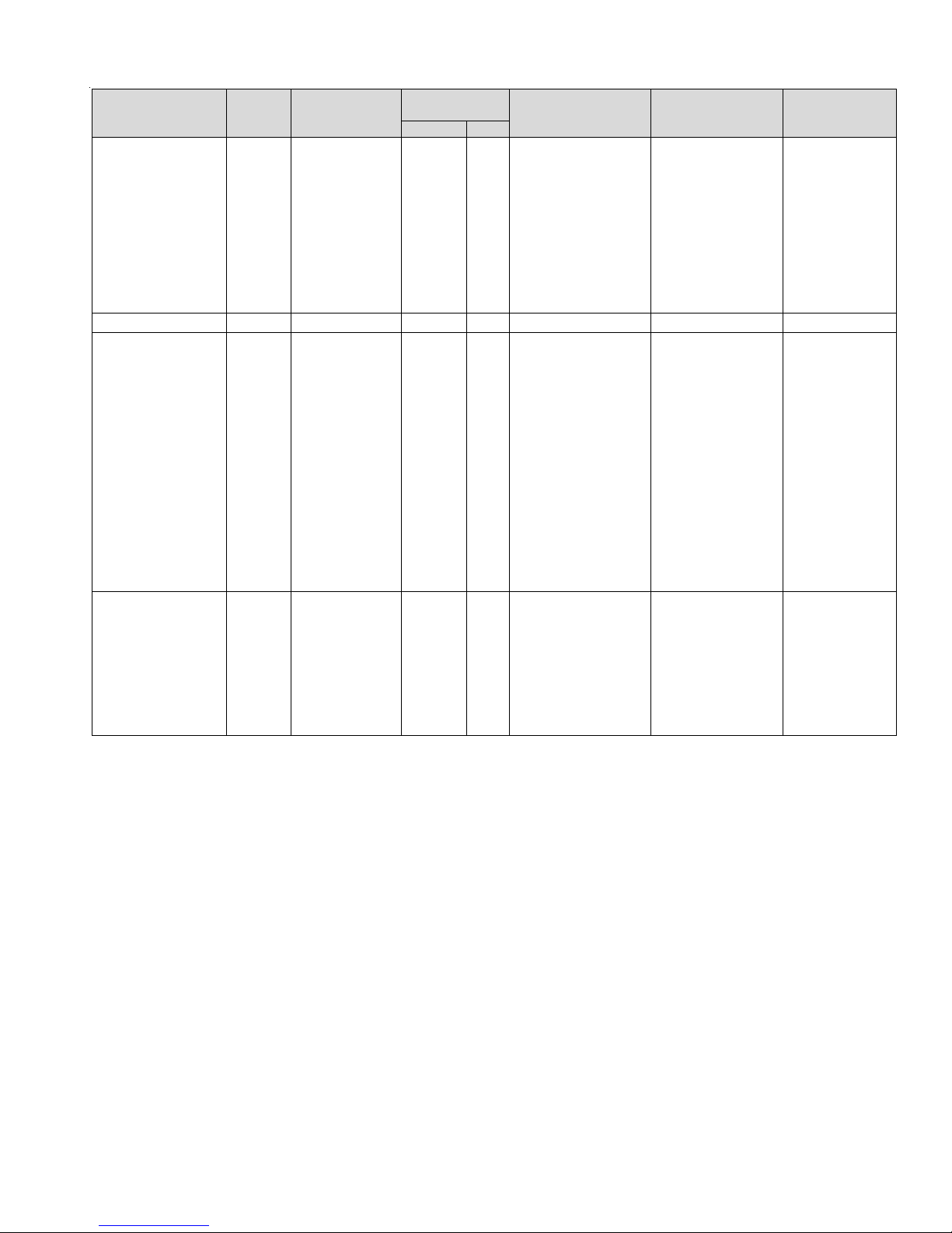
TROUBLESHOOTING
Symptoms of Abnormal
Operation (Legacy &
ComfortNet™ Thermostat)
• Furnace fails to operate
• Integrated control module
LED display provides no
signal.
• ComfortNet™ thermostat
“Call for Service” icon
illuminated
• ComfortNet™ thermostat
scrolls “Check Furnace”
message
• LED display indicates On On • Normal operation None No ne • Normal operation • None • Normal operation
• Furnace fails to operate
• Integrated control module
LED display provides E0
error code.
• ComfortNet™ thermostat
“Call for Service” icon
illuminated.
• ComfortNet™ thermostat
scrolls “Check Furnace”
message.
• Furnace fails to operate.
• Integrated control module
LED display provides E1
error code.
• ComfortNet™ thermostat
“Call for Service” icon
illuminated.
• ComfortNet™ thermostat
scrolls “Check Furnace”
message.
Diagnostic/
Status LE D
Codes
None • No 115 power to
E0 • Furnace l ock out
E1 • Low stage pressure
Fault Description
furnace or no 24 volt
power to integrated
control module
•Blown fuse or circuit
breaker
• Integrated control
module has an
internal fault
due to an excessive
number of ignition
“retries” (3 total)
switch circuit is
closed at start of
heating cycle.
ComfortNet™
Thermostat Only
Message Code
INTERNAL
FAULT
LOCKOUT E0 • Failure to establish fame.
PS1
CLOSED
EE • Manual disconnect switch
E1 • Low stage pressure switch
Possible Causes Corrective Actions Notes & Cautions
OFF, door switch open or
24 volt wir e improperly
connected or loose
• Blown fuse or circuit
breaker
• Integrated control module
has an internal fault
Cause may be no gas
to burners, front cover
pressure swi t ch st uck
open, bad igniter or igniter
alignment, improper
orifces, or coated/oxidized
or improperly connected
fame sensor.
• Loss of fame after
establishment. Cause
may be in te rrupted gas
supply, lazy burner fames
(improper gas pressure
or restriction in fue and/
or combustion air piping),
front cover pressure switch
opening, or improper
induced draft blower
performance.
contacts sticking.
• Shorts in pressure switch
circuit wiring.
• Assure 115 and 24
volt power to furnace
and integrated control
module.
• Check integrated control
module fuse (3A).
Replace if necessary.
• Check for possible
shorts in 115 and 24
volt circuits. Repair as
necessary.
• Replace bad integrated
control module.
• Locate and correct gas
interruption.
• Check f r o nt cover
pressure switch operation
(hose, wiring, contact
operation). Correct if
necessary.
• Replace or realign igniter.
• Ch eck fame sense
signal. Sand sensor if
coated and/or oxidized.
• Check fue piping for
blockage, proper length,
elbows, and termination.
• Verify proper induced
draft blower performance.
• Replace low stage
pressure switch.
• Repair short in wiring.
• Turn power OFF prior
to repair.
• Replace integrated
control module fuse
with 3A automotive
fuse.
• Read precautions
in “Electrostatic
Discharge” section of
manual.
•Replace control with
correct replacement
part
• Turn power OFF prior
to repair.
• Igniter is fragil e,
handle with care.
• Sand fame sensor
with emery cloth.
• See “Vent/Flue Pipe”
section for piping
details.
• Turn power OFF prior
to repair.
• Replace pressure
switch with proper
replacement part.
45
Page 46

TROUBLESHOOTING
Symptoms of Abnormal
Operation (Legacy
& ComfortNet ™
Thermostat)
• Induced draft blower
runs continuously with no
further furnace operation.
• Integrated control module
LED display provides E2
error code.
• ComfortNet™ thermostat
“Call for Service” icon
illuminated.
• ComfortNet™ thermostat
scrolls “Check Furnace”
message.
• Circulator blower
runs continuously. No
furnace operation.
• Integrated control
module LED display
provides E3 error code .
•ComfortNet™
thermostat “Call
for Service” icon
illuminated.
•ComfortNet™
thermostat scrolls
“Check Furnace”
message.
• Induced draft blower
and circulator blower
runs continuously. No
furnace operation.
• Integrated control
module LED display
provides E4 error code .
•ComfortNet™
thermostat “Call
for Service” icon
illuminated.
•ComfortNet™
thermostat scrolls
“Check Furnace”
message.
• No furnace operation.
• Integrated control
module LED display
provides E5 error code .
•ComfortNet™
thermostat displays
“Battery P ower”
• Normal fu rnace
operation.
• Integrated control
module LED display
provides E6 error code .
Diagnostic/
Status LE D
Codes
E2 • Low stage
E3 • Primary limit or
E4 • Flame sen sed
E5 • Open Fuse Not
E6 • Flame sense
Fault Des cription
pressure switch
circuit is not
closed.
auxiliary limit
circuit is open.
• Rollout limit
circuit is open.
with no call for
heat.
micro amp signal
is low
ComfortNet™
Thermostat Only
Message Code
PS1 OPEN E2 • Pressure switch hose
HIGH L I M I T
OPEN
IMPROPER
FLAME
Displayed
WEAK
FLAME
E3 • Insuffcient conditioned
E4 • Short to ground in
Not
Displayed
E6 • Flame sensor is
Possible Causes Corrective Actions Notes & Cautions
blocked pinched, or
connected improperly.
• Blocked fue and/or inlet
air pipe, blocked drain
system or weak induced
draft blower.
• Incorrect pressure
switch se t poi n t or
malfunctioning switch
contacts.
• Loose or improperly
connected wiring.
air over the heat
exchanger . Blocked
flters, restrict ive
ductwork, improper
circulator blower
speed, or failed
circulator blower motor.
• Flame rollout.
• Misaligned burners,
blocked fue and/or
air inlet pipe, or failed
induced draft blower.
• Loose or improperly
connected wiring.
fame sense circuit.
• Lingering burner fame.
• Slow closing gas valve.
• Short in low voltage
wiring
coated/oxidized.
•Flame sensor
incorrectly positioned
in burner fame.
• Lazy burner fame
due to improper gas
pressure or combustion
air.
• Inspect pressure switch
hose. Repair/replace if
necessary.
• Inspect fue and/or inlet
air piping for blockage,
proper length, elbows,
and termination. Check
drain system. Correct as
necessary.
• Check induced draft
blower performance.
Correct as necessary.
• Correct pressure switch
set point or contact
motion.
• Tighten or correct wiring
connection.
• Check flters and
ductwork for blockage.
Clean flters or remove
obstruction.
• Check circulator
blower speed and
performance. Correct
speed or replace blower
motor if necessary.
• Check burners for
proper alignment.
• Check fue and air inlet
piping for blockage,
proper length, elbows,
and termination.
Correct as necessary.
• Check induced draft
blower for proper
performance. Replace if
necessary.
• Tighten or correct
wiring connection.
• Correct short at fame
sensor or in fame
sensor wiring.
• Check for lingering
fame.
• V erify proper operation
of gas valve.
• Locate and correct
short in lo w vol tage
wiring
• Sand fame sensor if
coated/oxidized.
• Inspect for proper
sensor alignment.
• Check inlet air piping
for blockage, proper
length, elbows, and
termination.
• Compare current gas
pressure to rating plate.
Adjust as needed.
• T urn power OFF prior
to repair.
• Replace pressure
switch with proper
replacement part.
• Replace induced draft
blower with proper
replacement part.
• Turn power OFF
prior to repair.
• See Specifcation
Sheet applicable
to your model* for
allowable rise range
and proper circulator
speed.
• See "Vent/Flue Pipe"
section for piping
details.
• Turn power OFF
prior to repair.
• Turn power OFF
prior to repair.
• Replace fuse with
3-amp automotive
type
• Turn power OFF
prior to repair.
• Sand fame sensor
with emery cloth.
• See "Vent/Flue Pipe"
section for piping
details.
• See rating plate for
proper gas pressure.
46
Page 47

TROUBLESHOOTING
Symptoms of Abnormal
Operation (Legacy
& Com f ortNet ™
Thermostat)
• Furnace fails to operate.
• Integrated control
module LED display
provides E7 error code.
•ComfortNet™
thermostat “Call
for Service” icon
illuminated.
•ComfortNet™
therm o stat scr o l ls
“Check Furnace”
message.
• Furnace fails to operate
on high stage; furnace
operates normally on low
stage.
• Integrated control module
LED display provides E8
error code.
• Furnace fails to operate
on high stage; furnace
operates normally on low
stage.
• Integrated control module
LED display provides E9
error code.
• Furnace fails to operate.
• Integrated control module
LED display provides EA
error code.
• ComfortNet™ therm ostat
“Call for Service” icon
illuminated.
• ComfortNet™ therm ostat
scrol ls “Ch eck Furna ce”
message.
• Integrated control
module LED display EF
error code.
• ComfortNet™ therm ostat
“Call for Serv ic e ” .
Diagnostic/
Status LE D
Codes
E7 • Problem with
E8 • High stage
E9 • High stage
EA • Polarity of 115 volt
EF • Aux switch open Aux Alarm
Fault Description
igniter circuit.
pressur e swi tch
circu i t is clo se d
at start of heating
cycle.
• Induced draft
blower is
operating.
• Furnace is
operating on low
stage only
pressur e swi tch
circuit is not
closed.
• Induced draft
blower is
operating.
• Furnace is
operating on low
stage only
AC is reversed
PS2 CLOSED E8 • High stage press ure
ComfortNet™
Thermostat Only
Message Code
IGNITER
FAULT
PS2 OPEN E9 • Pressure switch hose
REVERSED
PLTY
Fault
E7 • Improperly connec ted
EA • P olarity of 115 volt AC
EF • High water level in the
Possible Causes Corrective Actions N otes & Cautions
igniter .
• Shorted igniter.
• Poor unit ground.
• Igniter relay fault on
integrated control
module.
switch contacts sticking.
• Shorts in pressure
switch circuit wiring.
blocked pinched, or
connected improperly.
• Blocked fue and/or inlet
air pipe, blocked drain
system or weak induced
draft blower.
• Incorrect pressure
switch set point or
malfunctioning switch
contacts.
• Loose or i mproperly
connected wiring.
power to furnace or
integrated module is
revered.
• Poor unit ground
evaporation coil.
• Check and correct
wiring from integrated
control module to
igniter .
• Replace shorted igniter.
• Check and correct unit
ground wiring.
• Check igniter output
from control. Replace if
necessary.
• Replace high stage
pressure switch.
• Repair short in w iring
• Inspect pressure switch
hose. Repair/replace if
necessary.
• Inspect fue and/or inlet
air piping for blockage,
proper length, elbows,
and termination. Check
drain system. Correct as
necessary.
• Check induced draft
blower performance.
Correct as necessary.
• Correct pressure switch
set point or contact
motion.
• Tighten or correct wiring
connection.
• Review wiring diagram to
correct polarity.
• Verify proper gr ound.
Correct if necessary .
• Check and correct
wiring.
• Check overfow pan and
service.
• Turn power OFF
prior to repair.
• Replace igniter with
correct replacement
part.
• Replace control with
correct replacement
part.
• Turn power OFF prior
to repair.
• Replace pressure
switch with proper
replacement part.
• Turn power OFF prior
to repair.
• Replace pressure
switch with proper
replacement part.
• Replace induced draft
blower with proper
replacement part.
• Turn power OFF prior
to repair.
• Turn power OFF prior
to service.
• Furnace fails to operate.
• Integrated control module
LED display provides d0
error code.
• ComfortNet™ therm ostat
“Call for Service” icon
illuminated.
• ComfortNet™ therm ostat
scrol ls “Ch eck Furna ce”
message.
d0 • Data not yet on
network.
NO NET
DA TA
d0 • Furnace does not
contain any shared data.
• Populate shared data
set using memory card.
• Turn power OFF prior
to repair
• Use m emory card for
the specifc model.
• Insert memory card
BEFORE turning
power ON. Memory
card may be removed
after data is loaded
and power is turned
off.
• Error code will be
cleared once data is
47
Page 48

TROUBLESHOOTING
Symptoms of Abnormal
Operation (Legacy
& ComfortNet™
Thermostat)
• Operation different than
expected or no operation.
• Integrated control
module LED display
provides d4 error code.
• ComfortNet™ thermostat
“Call for Se rvice” icon
illuminated.
• ComfortNet™ thermostat
scro ll s “ Check Furna ce”
message.
• Furnace fails to operate.
• Integrated control
module LED display
provides b0 error code.
• ComfortNet™ thermostat
“Call for Se rvice” icon
illuminated.
• ComfortNet™ thermostat
scro ll s “ Check Furna ce”
message.
• Furnace fails to operate.
• Integrated control
module LED display
provides b1 error code.
• ComfortNet™ thermostat
“Call for Se rvice” icon
illuminated.
• ComfortNet™ thermostat
scro ll s “ Check Furna ce”
message.
• Furnace fails to operate.
• Integrated control
module LED display
provides b2 error code.
• ComfortNet™ thermostat
“Call for Se rvice” icon
illuminated.
• ComfortNet™ thermostat
scro ll s “ Check Furna ce”
message.
• Furnace operates at
reduced performance.
• Airfow delivered is less
than expected.
• Integrated control
module LED display
provides b3 error code.
Diagnostic/
Status LED
Fau lt Descrip tion
Codes
d4 • Invalid memory
b0 • Circulator blow er
b1 • Integrated control
b2 • Circulator blow er
b3 • Circulator blow er
card data.
motor is not
running when it
should be running.
module has lost
communic ations
with circulator
blower motor.
motor horse
power in shared
data set does not
match circulator
blower motor
horse pow er.
motor is operating
in a power,
temperature, or
speed limiting
condition.
ComfortNet™
Thermostat Only
Message Code
INVALID MC
DA TA
MOTOR NOT
RUN
MOTOR
COMM
MOTOR
MISMATCH
MOTOR
LIMITS
Possible Causes Corrective Actions Notes & Cautions
d4 • Shared data set on
memory card has been
rejected by integrated
control module
b0 • Loose wiring connection
at circulator motor
power leads or
circulator motor power
leads disconnected.
• Open circuit in inductor
or loose wiring
connection at inductor
(3/4 Hp and 1 Hp
models only).
• Failed ci r cul at or blower
motor.
b1 • Loose wiring connection
at circulator motor
control leads.
• Failed ci r cul at or blower
motor.
• Failed integrated control
module.
b2 • Incorrect circulator
blower motor in furnace.
• Incorrect shared data
set in integrated control
module.
b3 • Blocked flters.
• Restrictive ductwork.
• Undersized ductwork.
• High ambient
temperatures.
• Verify sha r e d data set is
correct for the specifc
model. Re-popul ate data
using correct memory
card if required.
• Tighten or correct wiring
connection.
• V erify continuous
circuit through inductor.
Replace if open or short
circuit.
• C heck circulator blower
motor. Replace if
necessary.
• Tighten or correct wiring
connection.
• C heck circulator blower
motor. Replace if
necessary.
• C heck in tegr at e d con t ro l
module. Replac e if
necessary.
• V erify circulator blower if
motor horse power is the
same specifed for the
specifc furnace model.
Replace if nec ess ary.
• Verify sha r e d data set is
correct for the specifc
model. Re-popul ate data
using correct memory
card if required.
• C h e ck fl t e r s for
blockage. Clean flters
or remove obstruction.
• C heck duct wo rk for
blockage. Remove
obstruction. Verify all
registers are fully open.
•Verify ductwork is
appropriately sized for
system. Resize/ replace
ductwork if necessary.
•See "III. Product
Description" and "IV.
Location R eq u ir ements
& Considerations"
furnace installation
requirements.
• Turn power OFF prio r
to repair
• U se memory card for
the specifc model.
• Insert memory card
BEFORE turning
power ON. Memor y
card may be remove d
after data is load ed
and power is tur ned
off.
• Error code will be
cleared once data is
loaded and power is
turned off.
• Turn power OFF prio r
to repair
• Replace inductor with
correct replacement
part.
• Rep la ce ci r cul at or
motor with correct
replacement part.
• Turn power OFF prio r
to repair
• Rep la ce ci r cul at or
motor with correct
replacement part.
• Replace integrated
control module with
correct replacement
part.
• Turn power OFF prio r
to repair
•Replace motor with
correct replacement
part.
• U se memory card for
the specifc model
• Insert memory card
BEFORE turning
power ON. Memor y
card may be remove d
after data is load ed
and power is tur ned
off.
• Error code will be
cleared once shared
data and motor horse
power matc h .
• Turn power OFF prio r
to repair.
48
Page 49

TROUBLESHOOTING
Symptoms of Abnormal
Operation (L egacy
& ComfortNet™
Thermostat)
• Furnace fails to operate.
• Integrated control
module LED display
provides b4 error code.
• ComfortNet™ thermostat
“Call for Service” icon
illuminated.
• ComfortNet™ thermostat
scrol ls “Che ck Furnac e”
message.
Diagnostic/
Status LED
Codes
b4
Faul t D es cription
•
Circulator blower
motor senses
a loss of rotor
control.
• Circulator blo wer
motor senses
high current.
ComfortNet™
Thermostat Only
Message Code
MOTOR
TRIPS
b4 • Turn power OFF prior
Possible Causes Corrective Actions Notes & Cautions
to repair
• Furnace fails to operate.
• Integrated control
module LED display
provides b5 error code .
• ComfortNet™ thermostat
“Call for Service” icon
illuminated.
• ComfortNet™ thermostat
scrolls “Check Furnace”
message.
• Furnace fails to operate.
• Integrated control
module LED display
provides b6 error c ode.
• ComfortNet™ thermostat
“Call for Serv ice” icon
illuminated.
• ComfortNet™ thermostat
scrolls “Check Furnace”
message.
• Furnace fails to operate.
• Integrated control
module LED display
provides b7 error c ode.
• ComfortNet™ thermostat
“Call for Serv ice” icon
illuminated.
• ComfortNet™ thermostat
scrolls “Check Furnace”
message.
• Circulator blo wer
b5
b6 MOTOR
moto r fa i ls to start
10 consecutive
times.
•
Circulator blower
motor shuts down
MOTOR LCKD
ROTOR
VOLTS
for over or under
voltage condition.
•
Circulator blower
motor shuts
down due to
over temperature
condition on
power module.
•
b7 MOTOR
Circulator blower
motor does not
have enough
information to
operate properly.
Motor fails to start
PARAMS
40 consecutive
times.
b5 • Turn power OFF prior
•
b6 • Turn power OFF prior
•
•
b7
•
•
to repair.
• Replace motor with
correct replacement
part.
• Replace wheel with
correct replacement
part.
to repair
•
•
• Furnace operates at
reduced performance or
operates on low stage
when high stage is
expected.
• Integrated control
module LED dis play
provides b9 error code .
•
b9 LOW ID
Airflow is lower
than demanded.
AIRFLOW
B9 • Blocked filters.
• Restrictive ductwork.
• Undersized ductwork.
• Check filters for
blockage. Clean filters
or remove obstruction.
• Check ductwork for
blockage. Remove
obstruction. V erify all
registers are fully open.
• V erify ductwork is
appropriately sized for
syste m. Resize/replace
ductwork if necessary.
• Turn power OFF prior
to repair.
49
Page 50

TROUBLESHOOTING
n
O
E0
1
E
E2
E3
4
E
E5
E6
E7
E8
E9
E A
EF
0
d
4
d
INTERNAL CONTROL FAULT/NO
NORMAL OPERATION
LO CKOUT DUE TO EXCESSIVERE TRIES
LOW STAGE PRESSURE SWITCH STUCK CLOSED AT START OF HEA TING CYCLE
LOW STAGE PRESSURE SWITCH STUCK OPEN
OPEN HIGH LIMIT
FLAME DETECTED WHEN NO FLAME SHOULD BE PRESENT
OPE N FU SE
LOW FLAME SIGNAL
IGNITER F AUL T OR IMP ROPER GROUN DI NG
HIGH STAGE PRESSURE SWITCH STUCK CLO SED AT START O F HEATING CYCLE
HIGH STAGE PRESSU RE SWITCH STUCK
REVERSED 115 VAC POLARITY
AUXILIARY SWITCH OPEN
DATA NOT YET ON NETWORK
INVALID M E MORY CARD DATA
SWITCH
POWER
OPEN
BLOWER MO TOR NOT R UN NING
0
b
BLOW ER COMMUNICATION ERROR
b1
BLOW ER HP MIS-M ATCH
b2
BLOW ER MOTOR OPERATING IN PO W ER, TEMPERATURE, OR SPEED LIMIT
b
3
BLOWER MOTOR CURRENT TRIP O R LOST
4
b
BLOWER MOTOR LOCKED ROTOR
b5
OVER/UNDER VOLTAGE TRIP OR OVER TEMPERATURE TRIP
b6
INCOM PLET E PARAMETERS SENT T O
b
7
LOWINDOO RAIRFLOW
b9
LOW STAGE COO L
1
C
C2
HI
HIGH ST AG ECO O L
LOW STAGE H EAT PUMP H EAT
P1
P2
HIGH STAGE HEAT PUMP
0
L
LOW STAGE G AS
HIGH STAGE GAS HEAT
CONT INUO US FAN
F
HEAT
HEAT
ROTOR
MOTOR
CFM/100; AL TERNA TES WITH
12
50
1
C2
LO
C
, , , ,
P1 P2
,
H
I
F
0140F011 69REV A
Page 51

SYSTEM OPERATION
ComfortNet™ System
OVERVIEW
The ComfortNet system is a system that includes a
ComfortNet compatible furnace and air conditioner or heat
pump with a CTK0*** thermostat. A valid ComfortNet system could also be a compatible furnace, CTK0*** thermostat and non-communicating, single stage air conditioner.
Any other system configurations are considered invalid
ComfortNet systems and must be connected as a traditional (or legacy) system (see Electrical Connections for
wiring connections).
A ComfortNet heating/air conditioning system differs from
a legacy/traditional system in the manner in which the indoor unit, outdoor unit and thermostat interact with one
another. In a traditional system, the thermostat sends
commands to the indoor and outdoor units via analog 24
VAC signals. It is a one-way communication path in that
the indoor and outdoor units typically do not return information to the thermostat.
On the other hand, the indoor unit, outdoor unit, and thermostat comprising a ComfortNet system “communicate”
digitally with one another. It is now a two-way communications path. The thermostat still sends commands to the
indoor and outdoor units. However, the thermostat may
also request and receive information from both the indoor
and outdoor units. This information may be displayed on
the ComfortNet thermostat. The indoor and outdoor units
also interact with one another. The outdoor unit may send
commands to or request information from the indoor unit.
This two-way digital communications between the thermostat and subsystems (indoor/outdoor unit) and between subsystems is the key to unlocking the benefits and features
of the ComfortNet system.
Two-way digital communications is accomplished using
only two wires. The thermostat and subsystem controls
are power with 24 VAC. Thus, a maximum of 4 wires between the equipment and thermostat is all that is required
to operate the system.
OPERATIONS WITH CTK03AB AND CTK04
1. Humidification Options are ON / OFF with the CTK03AB.
When “On” is selected, the humidification relay on the
furnace control board will function during a heat call if a
humidity demand exists. Selecting “Off” means the
humidification relay will not function.
2. If the CTK03AB and CTK04 are set up so the compressor off delay is 0 min, it will display a cool / heat call
immediately regardless of the delay built into the outdoor unit control board. This means the CTK03A* could
show COOL ON when the outdoor unit is still in a delay
period. The recommendation is to set up the compressor delay to at least 3 minutes
3. Dual Fuel – When the CTK03AB and CTK04 call for
gas heat, the heat pump will shut off, after a delay of
approximately 3 minutes it will then turn on gas heat.
ComfortNet™ System
4. Dehumidification (lowering of CFM to 85%) only happens
during low stage cooling operation. The dehumidification
feature is not active during high stage cool. The CTK03AB
and CTK04 can be set up to overcool the home in order
to reach the RH set point.
CTK0*** WIRING
NOTE: Refer to Electrical Connections for 115 volt line
connections to the furnace.
NOTE: A removable plug connector is provided with the
control to make thermostat wire connections. This plug may
be removed, wire connections made to the plug, and replaced.
It is recommended that multiple wires be connected with a
wire nut and only one wire be inserted under a screw. Failure
to do so may result in intermittent operation.
Typical 18 AWG thermostat wire may be used to wire the
system components. However, communications reliability
may be improved by using a high quality, shielded, twisted
pair cable for the data transmission lines. In either case,
100 feet is the maximum length of wire between indoor unit
and outdoor unit, or between indoor unit and thermostat.
FOUR-WIRE INDOOR AND OUTDOOR WIRING
Typical wiring will consist of four wires between the indoor
unit and outdoor unit and between the indoor unit and thermostat. The required wires are: (a) data lines, 1 and 2; (b)
thermostat “R” (24 VAC hot) and “C” (24 VAC common).
C
1
2
12RC
12RC
TWO-WIRE OUTDOOR, FOUR-WIRE INDOOR WIRING
Two wires only may be utilized between the indoor and outdoor units. For this wiring scheme, only the data lines, 1
and 2, are required between the indoor and outdoor units. A
40VA, 208/230 VAC to 24VAC transformer must be installed
in the outdoor unit to provide 24VAC power to the outdoor
unit’s electronic control.
CTK0***
Thermostat
R
ComfortNet Compatible Furnace
Integrated Control Module
ComfortNet Compatible AC/HP
Integrated Control Module
51
Page 52

SYSTEM OPERATION
NOTE: Use of an accessory transformer is recommended if
installing a dual fuel system. Failure to use the transformer
in the outdoor unit could result in overloading of the furnace
transformer.
When using a CTK03A*or CTK04 thermostat, the included
transformer must be used.
If your communicating thermostat kit does not include a
transformer, an accessory kit is available separately by
ordering part TFK01.
ComfortNet™ System
1
2R
12RC
C
C Y
CTK0***
Thermostat
W1 W2 Y1 Y2
G
ComfortNet
O
Non-ComfortNet Compatible
Single Stage AC
Compatible
Furnace Inte grated
Control Module
40V A Transformer
208/230 VAC
1
2R
12RC
12
24 VAC
CTK0***
C
Thermostat
ComfortN et Compatible
Furnace Integrated
Control Module
ComfortNet Compatible
RC
AC/HP Integrated
Control Module
SYSTEM WIRING USING TWO-WIRES BETWEEN FURNACE AND
FOUR-WIRES BETWEEN FURNACE AND THERMOSTAT
COMFORTNET FURNACE WITH NON-COMFORTNET A/C
S
INGLE STAGE AIR CONDITIONER
Four wires are required between the furnace and thermostat. Two wires are required between the furnace control
and single stage air conditioner. For this system configuration, the “Y1” terminal on the integrated furnace control becomes an output rather than an input.
SYSTEM WIRING BETWEEN FURNACE AND NON-COMFORTNET
COMPATIBLE SINGLE STAGE AIR CONDITIONER
COMFORTNET SYSTEM ADVANCED FEATURES
The ComfortNet system permits access to additional system information, advanced setup features, and advanced diagnostic/troubleshooting features. These advanced features
are organized into a menu structure.
52
Page 53

SYSTEM OPERATION
FURNACE ADVANCED FEA TURES MENUS
Submenu Item Indication (for Display Only; not User Modifiable)
Nu mb er of Heat Stages (HT S TG) Displays the number of fur nace heating st ages
I n p ut Rate (BTU/ H R) Dis p lays t h e furnace input rate i n kBtu/h r
Mot or HP ( 1/2, ¾ , or 1 MTR HP) D isplays the furnace ind oor blow er motor hor s epowe r
Submenu Item Indication/Use r Modifiable Options Comments
Fault 1 (FAULT #1) Most recent furnace fault For display only
Fault 2 ( FAULT #2) Ne x t mos t re c ent fur nac e fault For dis play only
Fault 3 ( FAULT #3) Ne x t mos t re c ent fur nac e fault For dis play only
Fault 4 ( FAULT #4) Ne x t mos t re c ent fur nac e fault For dis play only
Fault 5 ( FAULT #5) Ne x t mos t re c ent fur nac e fault For dis play only
Fault 6 (FAULT #6) Least recent furnace fault For display only
Clear F ault History (CLEA R) NO or Y ES
NOTE:
Consecutively repeated faults are shown a maximum of 3 times.
ComfortNet™ System
CONFIGURATION
DIAGNOSTICS
Selecti ng “YES” clears th e
fault hist or y
IDENTIFICATION
Submenu Item Indication (for Display Only; not User Modifiable)
Model Nu m ber ( M OD NU M ) Displays the furnace m odel n um ber
Serial Number ( S E R NUM) Displays the furnace se r ial nu mb er ( Optional)
Software (SOFTWARE) Displays the application software revision
SET-UP
Submenu Item User Modifiable Options Comme nts
Heat Airflow Trim (HT
TRM)
Heat ON Delay (HT ON 5, 10, 15, 20, 25, or 30 seconds,
Heat O FF Delay ( HT OFF) 30, 60, 90 , 12 0, 150, or 180
Heat Airflow (HT ADJ ) 1, 2, 3, or 4 Se lec ts the nominal heat ing airflow (see
-10% to +10% in 2% increments,
de fa ul t is 0%
d e f a ul t is 30 se c o nds
seconds, d efault is 150 secon ds
STATUS
Tr im s the hea ting airflow by the se le cted
amount.
Selects th e i ndoor bl ower heat ON delay
Selects th e i ndoor bl ower heat OFF de lay
Startup Procedure and Adjustment –
Circulator Blower Speeds for additional
information)
Submenu Ite m Indication (for Display Only; not User Modifia ble)
Mode (MODE) Displays the current furnace operating mode
CFM ( CFM) Display s the airflow for the current operat ing mode
53
Page 54

SYSTEM OPERATION
NON- C O M M (A P P LI E S ONL Y TO A COM MUNICAT ING COMPATIBL E FURNACE MATCHED
WITH A NON - COM MUNICATING COMPATIBLE SINGL E STAGE AIR CONDITIONER)
Subm e nu Item U s er Mo difiab le Options Co m ments
Cool Air flow (C L CFM) 18, 24, 30, 36, 42, 48, or 60, default
is 18
ComfortNet™ System
Sele c ts the airflow for the non-CT
comp atib le sing l e s tag e A C un it
Cool Airflow Trim (CL TRM) -10% to +10% in 2% increments,
d efault is 0%
Cool A ir flow Profile (CL P RFL) A, B , C, or D, default is A Sele c ts the airflow profile for the non-
Cool ON Delay (CL ON) 5, 10, 20, or 30 seconds, default is
5 secon ds
Cool OFF Delay (CL OFF) 30, 60, 90, or 120 seconds, default
is 30 sec o nd s
THERMOSTAT MENU
If this furnace is installed with a ComfortNet compatible heat
pump, the system is recognized as a dual fuel system. The
balance point temperature should be set via the thermostat
advanced menu.
bank of two dipswitches that provide termination functions
for the communications transmission lines. Communications errors will result if these switches are not correctly
set. The table below indicates the switch position for the
bias and termination dipswitches along with the expected
Sele cts the airf low trim amount for the noncommunicating compatible s ingle stage AC
unit
communicating compatible s ingle stage AC
unit
Sele c ts t he ind oor blower ON delay for the
non - c om m unicat ing c om patible si ngle
st age A C unit
Sele c ts t he ind oor blower OFF dela y for t he
non - c om m unicat ing c om patible si ngle
st age A C unit
voltages. Note that the ON position is the correct position
DIAGNOSTICS
Accessing the furnace’s diagnostics menu provides ready
access to the last six faults detected by the furnace. Faults
are stored most recent to least recent. Any consecutively
repeated fault is stored a maximum of three times. Example:
A clogged return air filter causes the furnace limit to trip
repeatedly. The control will only store this fault the first three
for all bias and termination dipswitches.
The ComfortNet system is a fully communicating system,
and thus, constitutes a network. Occasionally the need to
troubleshoot the network may arise. The integrated furnace
control has some on-board tools that may be used to troubleshoot the network. These tools are: red communications
LED, green receive (Rx) LED, and learn button.
consecutive times the fault occurs. Navigate to the diagnostics menu as described above in Accessing and Navi-
gating the Advanced Features Menus.
• Red communications LED – Indicates the status of
the network. The table below indicates the LED
status and the corresponding potential problem.
NOTE: It is highly recommended that the fault history be
cleared when performing maintenance or servicing the
furnace.
NETWORK TROUBLESHOOTING
Communications is achieved by taking the difference between
two dc signals. The signals and transmission lines are re-
• Green receive LED – Indicates network traffic. The
table below indicates the LED status and the corresponding potential problem.
• Learn button – Used to reset the network. Depress
the button for approximately 2 seconds to reset the
network.
ferred to as “data 1” and “data 2”. Each transmission line is
biased to approximately 2.5Vdc. During data reception/transmission, the data lines vary between +5V and ground. (When
data 1 is increasing towards +5V, data 2 is decreasing towards ground and when data 1 is decreasing towards ground,
data 2 is increasing towards +5V. Typically, the data 1 line
is approximately 2.6Vdc and the data 2 transmission line is
approximately 2.3Vdc. The voltage difference between data
1 and data 2 is typically 0.2 to 0.6 Vdc.
The indoor control is equipped with a bank of three
dipswitches that provide biasing and termination functions
for the communications transmission lines. The outdoor
control in the ComfortNet compatible unit is equipped with a
54
Page 55

SYSTEM OPERATION
ComfortNet™ System
SYSTEM TROUBLESHOOTING
NOTE: Refer to the instructions accompanying the ComfortNet compatible outdoor AC/HP unit for troubleshooting information.
Refer to the Troubleshooting Chart for a listing of possible furnace error codes, possible causes and corrective actions.
LED LED
Status
1 Flash
Red
Communications
LED
2 Flashes
1 Steady
Flash
Green Receive
LED
Rapid
Flashing
On Solid
Off
Off
Indication Possible Causes Corrective Action(s) Notes & Cautions
x Normal condition x None x None x None
x Communications
Failure
x Out-of-box reset x Control power up
x No power
x Communications
error
x No network found x Broken/ disconnected
x Normal network
traffic
x Data 1/ Data 2
miss-wire
x Communications
Failure
x Learn button
depressed
x No power to furnace
x Open fuse
x Communications error
data wire(s)
x Furnace is installed as
a legacy/ traditional
system
x Control is “talking” on
network as expected
x Data 1 and data 2
wires reversed at
furnace, thermostat,
or CT™ compatible
outdoor AC/HP
x Short between data 1
and data 2 wires
x Short between data 1
or data 2 wires and R
(24VAC) or C (24VAC
common)
x Depress Learn Button
x Verify that bus BIAS
and TERM
dipswitches are in the
ON position.
x None x None
x Check fuses and
circuit breakers;
replace/reset
x Replace blown fuse
x Check for shorts in
low voltage wiring in
furnace/system
x Reset network by
depressing learn
button
x Check data 1/ data 2
voltages
x Check
communications
wiring (data 1/ data 2
wires)
x Check wire
connections at
terminal block
x Verify furnace
installation type
(legacy/ traditional or
communicating)
x Check data 1/ data 2
voltages
x None x None
x Check
communications
wiring (data 1/ data 2
wires)
x Check wire
connections at
terminal block
x Check data 1/ data 2
voltages
x Depress once
quickly for a powerup reset
x Depress and hold
for 2 seconds for
an out-of-box reset
x Turn power OFF
prior to repair
x Turn power OFF
prior to repair
x Verify wires at
terminal blocks are
securely twisted
together prior to
inserting into
terminal block
x Verify data1 and
data voltages as
described above
x Turn power OFF
prior to repair
x Verify wires at
terminal blocks are
securely twisted
together prior to
inserting into
terminal block
x Verify data1 and
data voltages as
described above
55
Page 56

SYSTEM OPERATION
ComfortNet™ System
TROUBLESHOOTING
ELECTROSTATIC DISCHARGE (ESD) PRECAUTIONS
NOTE: Discharge body’s static electricity before touching
unit. An electrostatic discharge can adversely affect electrical
components.
Use the following precautions during furnace installation and
servicing to protect the integrated control module from damage. By putting the furnace, the control, and the person at
the same electrostatic potential, these steps will help avoid
exposing the integrated control module to electrostatic discharge. This procedure is applicable to both installed and
uninstalled (ungrounded) furnaces.
1. Disconnect all power to the furnace. Do not touch the
integrated control module or any wire connected to
the control prior to discharging your body’s electrostatic charge to ground.
2. Firmly touch a clean, unpainted, metal surface of the
furnace away from the control. Any tools held in a
person’s hand during grounding will be discharged.
3. Service integrated control module or connecting wiring
following the discharge process in step 2. Use caution not to recharge your body with static electricity;
(i.e., do not move or shuffle your feet, do not touch ungrounded objects, etc.). If you come in contact with
an ungrounded object, repeat step 2 before touching
control or wires.
4. Discharge your body to ground before removing a new
control from its container . Follow steps 1 through 3 if
installing the control on a furnace. Return any old or
new controls to their containers before touching any
ungrounded object.
FOUR WIRE MOTOR TROUBLESHOOTING
Any manual testing of the 4 wire seriallY communicating
motor should only be done with the ULTRACHECK-EZ diagnostic tool (part # UTT-01). All other methods may not be
reliable or cause damage to the 4 wire motor. See section
S-16C for additional details.
COMFORTNET SYSTEM TROUBLESHOOTING
At system power-up, the CTK0*** thermostat will begin
searching for any connected compatible equipment. The
thermostat will scroll "SEARCHING". The thermostat will
scroll <equipment> FOUND once it indentifies that piece
of equipment. In a typical installation, an indoor unit and
outdoor unit will be identified.
Wiring issues may be confirmed (or eliminated) by using
the CTK0*** thermostat and sub base, a 4-position connector (included with the kit), and a short section (~ 2ft) of thermostat wire. Connect the wire between the connector and
thermostat sub base. Connect the thermostat to the indoor
unit and apply power. If the thermostat identifies the indoor
unit, then a wiring problem exists between the indoor unit
and the permanent thermostat location. Repair or replace
wiring.
Connect the thermostat to the outdoor unit. If the thermostat identifies the outdoor unit, then a wiring problem exists
between the indoor and outdoor units. Repair or replace
wiring.
NOTE: A 24VAC source will be needed to power the thermostat and outdoor unit control.
DIAGNOSTIC CHART
W ARN ING
HIGH VOLTAGE !
TO
AVOID PERSONAL INJURY OR DEATH DUE TO
ELECTRICAL SHOCK, DISCONNECT ELECTRICA L POWER
BEFORE
Refer to the Troubleshooting Chart in the Appendix for as-
sistance in determining the source of unit operational problems. The dual 7-segment LED display will display an error
code that may contain a letter and number. The error code
may be used to assist in troubleshooting the unit.
RESETTING FROM LOCKOUT
Furnace lockout results when a furnace is unable to achieve
ignition after three attempts during a single call for heat. It
is characterized by a non-functioning furnace and a E
code displayed on the dual 7-segment display. If the furnace is in “lockout”, it will (or can be) reset in any of the
following ways.
1. Automatic reset. The integrated control module will
2. Manual power interruption. Interrupt 115 volt power to
3. Manual thermostat cycle. Lower the thermostat so
PERFORMING ANY SERVICE OR MAINTENANCE
automatically reset itself and attempt to resume normal
operations following a one hour lockout period.
the furnace.
that there is no longer a call for heat for 1 -20 seconds
then reset to previous setting.
.
0
If the thermostat scrolls "SEARCHING" for several minutes,
then it has failed to identify any connected equipment. The
thermostat may identify one piece of equipment, but not the
other. Broken or improper wiring is the most likely cause for
the thermostat to fail to identify any equipment. If an outdoor unit is not identified, the thermostat will scroll "CHECK
SYSTEM", indicating that no indoor unit was found.
56
NOTE: If the condition which originally caused the lockout
still exists, the control will return to lockout. Refer to the
Diagnostic Chart for aid in determining the cause.
Page 57

SERVICING
Some of the electronic boards being used today, with flame
rectification, will not function properly and/or at all without
polarization of incoming power. Some also require phasing
between the primary and secondary sides of step-down
transformers.
METER READS
120 VOLTS
VOLT / OHM
METER
INCOMING POWER
GND
METER READS
0 VOLTS
GND
VOLT / OHM
METER
THIS IS L1 OR THE
HOT POWER LEG
These then should be wired to the furnace accordingly.
CHECKING FOR PHASING - PRIMARY TO SECONDARY OF UNMARKED TRANSFORMERS*
D
N
G
METER READS
24 VOLTS
.
.
.
.
.
.
VOLT / OHM
METE R
C
R
TRANSFORMER
D
N
G
SECONDARY
LINE VOLTAGE
(NEUTRAL)
PRIMARY
LINE VOLTAGE
L1 (HOT)
METER READS
120 VOLTS
VOLT / OHM
METE R
C
R
VOLT / OHM
METE R
READS 96 VOLTS - IN PHASE
D
N
G
C
R
N
L1
N
L1
THIS IS THE COMMON
OR NEUTRAL LEG
VOLT / OH M
M E TER
If meter reads approximately 96 volts - the primary to secondary are in phase - if reads approximately 144 volts out of phase
- reverse low voltage wires.
D
N
G
C
24 V
R
PHASING SYMBOL
120 V
NEUTRAL
L1
VOLT / OH M
M E TER
READS 144 VOLTS - OUT OF PHASE
Some transformers will display phasing symbols as shown
in the illustration to the left to assist in determining proper
transformer phasing.
57
Page 58
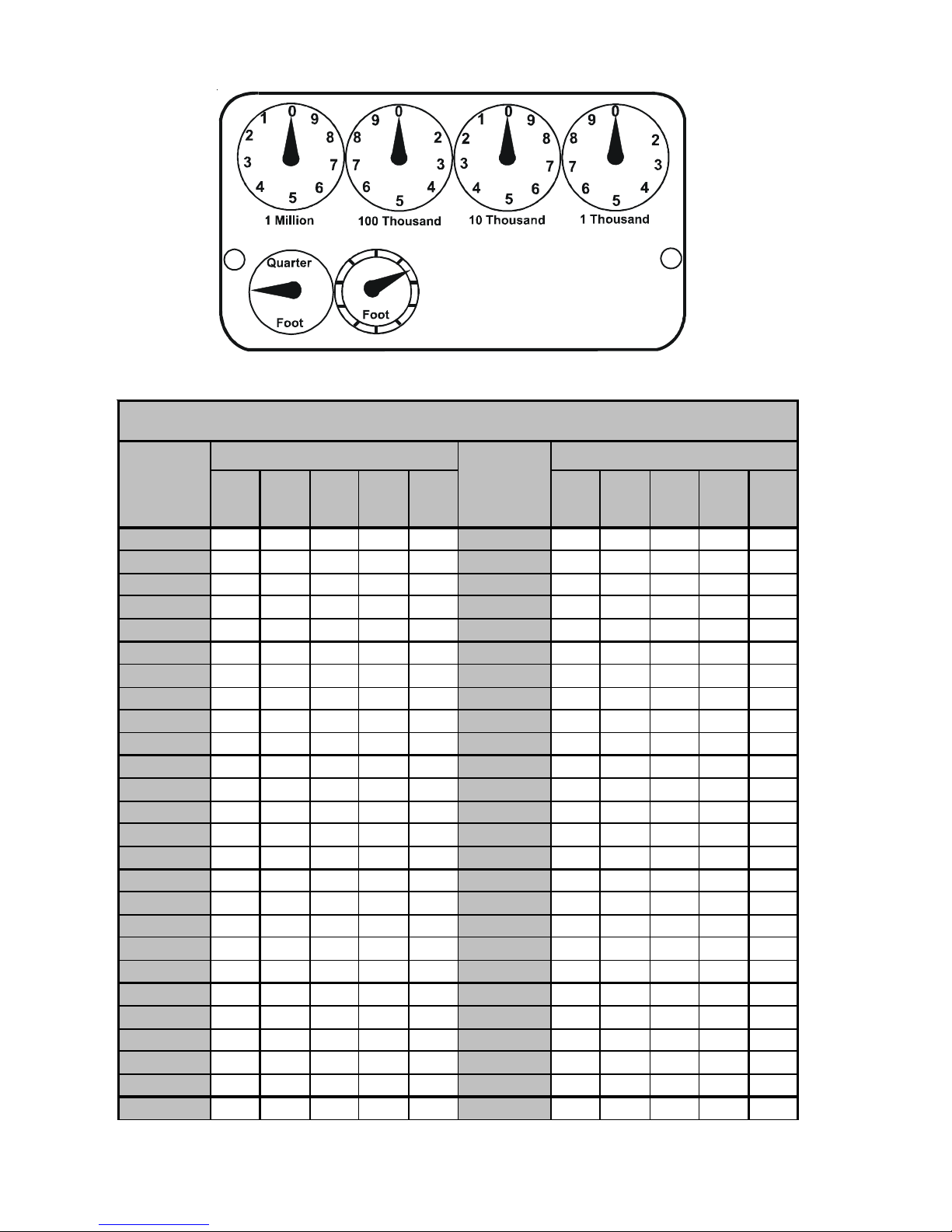
SERVICING
Seconds for
One
Revolutio n
10
11
12
13
14
15
16
17
18
19
20
21
22
23
24
25
26
27
28
29
30
31
32
33
34
35
1
One
G AS RA TE -- CUBIC FEET PER HO UR
Size of Test Dial
1/4
cu/ft
90 180 360 720 1800
82 164 327 655 1636
75 150 300 600 1500
69 138 277 555 1385
64 129 257 514 1286
60 120 240 480 1200
56 113 225 450 1125
53 106 212 424 1059
50 100 200 400 1000
47 95 189 379 947
45 90 180 360 900
43 86 171 343 857
41 82 164 327 818
39 78 157 313 783
37 75 150 300 750
36 72 144 288 720
34 69 138 277 692
33 67 133 265 667
32 64 129 257 643
31 62 124 248 621
30 60 120 240 600
28 56 113 225 563
26 53 106 212 529
1/2
cu/ft1cu/ft2cu/ft5cu/ft
-- -- 116 232 581
-- -- 109 218 545
-- -- 103 206 514
CUBIC
FEET
Seconds for
One
Revolution
36
37
38
39
40
41
42
43
44
45
46
47
48
49
50
51
52
53
54
55
56
57
58
59
60
1
Size of Test Dial
1/4
cu/ft
25 50 100 200 500
23 47 95 189 474
22 45 90 180 450
21 43 86 172 429
20 40 80 160 400
19 38 76 153 383
18 36 72 144 360
17 34 -- 136 340
16 32 64 129 321
15 30 60 120 300
1/2
cu/ft1cu/ft2cu/ft5cu/ft
-- -- 97 195 486
-- -- 92 185 462
-- -- -- 176 439
-- -- -- 167 419
-- 41 82 164 409
-- -- 78 157 391
-- -- 75 150 375
-- -- -- 147 367
-- -- -- 141 355
-- -- 69 138 346
-- -- 67 133 333
-- -- -- 131 327
-- -- -- 126 316
-- 31 62 124 310
-- -- -- 122 305
58
Page 59

SERVICING
Service Problem No Heat Un satisfactory Heat
POSSIB LE CAUSE
DOT S IN ANAL YSIS
GUIDE INDICATE
"POSSIBLE CAUSE"
Power Failure
Blown Fuse
L o ose Con n ec t i on
Shorted or Broken Wires
No Low V oltag e
Faulty Thermostat
Faulty Transformer
Poor or High Res istanc e Ground
Improper Heat Anticipator Setting
Improper Thermostat Location
Fa ulty Limit or Roll Out Switch
Faul ty Fl am e Senso r
F au l ty Ig ni tion C o nt ro l
Gas Valve or Gas Supply Shut Off
Faul ty In du c e d D r af t Blow e r
Faulty Blower Motor (ECM)
Broken or Shorted Ignitor
Dirty Flame Sensor, Low UA
Stuck Gas Valve
Faulty Gas Valve
Open Auxili ary Li mit
Improper Air Flow or Distribution
Cycling on Limit
Dela y e d I g ni t i o n
Flashback
Orifice Size
Gas Pre ssu r e
Cracked Hea t Exchanger
Furn ace Undersized
Furn ace Oversi z e d
Faulty Pressure Switch
Blocked or Restricted Flue
Open Ro ll Out S witch
Bouncin g On Press ur e Sw itc h
SYMPTOM
Burner Won't Ignite
S ys t em Wil l No t St ar t
Burner Ignites-Locks Out
B ur ner Shuts Off prio r to T'Stat being Satisf ied
•
•
•
•
•
•••••
•
•
••
•
•••
•
••
••
•
•
•••
•••
••
••
•• •
••••
•••
••
•
Lo ng Cycles
Short Cycles
Too Much Heat
So o t an d /o r Fu m es
Not Enough Heat
•• ••
•• ••
•
•
•••
•
••
•
•
Test Voltage S-1
Test Voltage S-4
Check Wiring S-2
Check Wiring S-3A
Check Transf ormer S- 4
Che ck Thermostat S-3A
Check Transf ormer S-4
Measure Ground Resistance S-17B
Adju st Heat An ticip at or Settin g S-3 B
Relocate Thermosta t S-316
Test Control S-300 / S-302
Test Flame Sensor S-314
Test Control S-313
Turn Valves to On Position S- 317
Te s t I n du c e d D r af t Mo tor S -3 0 3
Te s t Blo w e r Motor ( & EC M) S-16A,B ,C
Test Ignitor S-308
Clean Fl am e Sensor S-314
Replace Gas Valve S- 304
Replace Gas Valve S- 304
Res et Control S-301
Check Duct S tat i c S- 200
Chec k Controls & Temperature Rise S-201 / S -300
Tes t f or D elay ed Igni tion S- 312
Test for Flas hback S-309 / S-311
Check Orifices S-306 / S-311
Che ck Gas Pressure S-307
Check Burner Flames S-305
Replace w ith Proper S ize Furnace S-318
Replace w ith Proper S ize Furnace S-318
Test Pressure Switc h S-310
Check Flue /Dr awdown P r es sure S-310
Tes t Flame Roll Ou t C ontrol S-302
Test Negative Pressure S-310
Test Met hod
Remedy
See Service Procedure Reference
59
Page 60

SERVICING
SERVICE NUMBERS
S-1 CHECKING VOLT AGE ....................... 61
S-2 CHECKING WIRING .......................... 61
CHECKING THERMOST AT, WIRING
AND ANTICIP ATOR............................ 61
S-3A THERMOST AT AND WIRING ............. 61
S-3B HEATING ANTICIPATOR .................... 61
S-200 CHECKING DUCT STA TIC ................ 65
S-201 CHECKING TEMPERATURE RISE ... 65
S-300 CHECKING PRIMARY
LIMIT CONTROL ................................ 66
S-301 CHECKING AUXILIARY
LIMIT CONTROL ................................ 67
S-302 CHECKING FLAME ROLLOUT
CONTROL ......................................... 67
S-303 INDUCED DRAFT BLOWER Motor ... 68
S-304 CHECKING GAS VAL VE
(REDUNDANT) .................................. 68
S-305 CHECKING MAIN BURNERS............. 69
S-306 CHECKING ORIFICES....................... 69
S-307 CHECKING GAS PRESSURE ........... 69
S-308 CHECKING
HOT SURF ACE IGNITOR .................. 71
S-309 CHECKING FOR FLASHBACK.......... 72
S-310 CHECKING PRESSURE CONTROL. 72
S-311 HIGH ALTITUDE
APPLICA TION (USA).......................... 72
S-312 CHECKING FOR
DELA YED IGNITION........................... 73
S-313 CHECKING INTEGRATED
IGNITION CONTROL BOARDS ........ 73
S-313A MEMORY CHIPS................................ 74
S-314 CHECKING FLAME SENSOR.......... 75
60
Page 61

SERVICING
S-1 CHECKING VOLTAGE
CHECKING THERMOSTAT, WIRING
AND ANTICIPATOR
WARNING
HIGH VOLTAGE
D
ISCONNECT ALL POWER BEFORE SERVICI NG OR
CHANGING ANY E LECTRI CAL WI RING.
SOURCES MAY BE PRESENT.
PROPERTY DAMAGE, PERS ONAL INJURY OR DEATH.
MULTIPLE POWER
FAILURE TO DO SO MAY CAUSE
1. Remove the burner door.
2. Remove cover from the Junction Box and gain access to
incoming power lines.
With Power ON:
WARNING
LINE VOLTAGE NOW PRESENT
3. Using a voltmeter, measure the voltage across the hot
and neutral connections.
NOTE: To energize the furnace, the Door Interlock Switch
must be engaged at this point.
4. No reading - indicates open wiring, open fuse, no power,
or faulty Door Interlock Switch from unit to fused disconnect service. Repair as needed.
5. With ample voltage at line voltage connectors, energize
the furnace blower motor by jumpering terminals R to G
on the integrated ignition control.
6. With the blower motor in operation, the voltage should
be 1 15 volts ± 10 percent.
7. If the reading falls below the minimum voltage, check
the line wire size. Long runs of undersized wire can cause
low voltage. If wire size is adequate, notify the local power
company of the condition.
8. After completing check and/or repair, replace Junction
Box cover and reinstall the service panel doors.
9. Turn on electrical power and verify proper unit operation.
S-2 CHECKING WIRING
WARNING
DISCONNECT ALL POWER BEFORE SERVICING.
1. Check wiring visually for signs of overheating, damaged
insulation and loose connections.
2. Use an ohmmeter to check continuity of any suspected
open wires.
3. If any wires must be replaced, replace with AWM, 105°C.
2/64 thick insulation of the same gauge or its equivalent.
S-3A THERMOSTAT AND WIRING
WARNING
DISCONNECT ALL POWER BEFORE SERVICING.
1. Remove the blower compartment door to gain access to
the thermostat low voltage wires located at the furnace
integrated control module terminals.
2. Remove the thermostat low voltage wires at the furnace
control panel terminal board.
3. Jumper terminals R to W (or W1 and W2 for two-stage
models) on the integrated ignition control.
With Power On (and Door Interlock Switch closed):
WARNING
LINE VOLTAGE NOW PRESENT
4. Induced Draft Motor must run and pull in pressure switch.
5. If the hot surface ignitor heats and at the end of the
ignitor warm-up period the gas valve opens and the burners ignite, the trouble is in the thermostat or wiring.
6. With power off, check the continuity of the thermostat
and wiring. Repair or replace as necessary .
If checking the furnace in the air conditioning mode, pro-
ceed as follows.
7. With power off, Jumper terminals R to Y (or Y1 or Y2 for
two-stage models) to G.
8. Turn on the power.
9. If the furnace blower motor starts and the condensing
unit runs, then the trouble is in the thermostat or wiring.
Repair or replace as necessary .
10. After completing check and/or repair of wiring and check
and/or replacement of thermostat, reinstall blower compartment door .
1 1. Turn on electrical power and verify proper unit operation.
S-3B HEATING ANTICIPATOR
On older thermostats, the heating anticipator is a wire wound
adjustable heater which is energized during the "ON" cycle
to help prevent overheating of the conditioned space.
The anticipator is a part of the thermostat and if it should fail
for any reason, the thermostat must be replaced.
The heating anticipator setting for furnaces covered in this
manual is 0.70 Amps.
Modern thermostats do not have this type of heat anticipator. Many have a selector switch to adjust the number of
cycles per hour
61
Page 62
SERVICING
S-4 CHECKING TRANSFORMER AND Control CIRCUIT
A step-down transformer 120 volt primary to 24 volt secondary, 40 VA (Heating and Cooling Models) supplies ample
capacity of power for either operation.
WARNING
HIGH VOLTAGE
D
ISCO NNECT ALL POWER BEFORE SERVI CING OR
CHANGING ANY ELECTRICAL WIRING.
SOURCES MAY BE PRESENT.
PROPERTY DAMAGE, PERSONAL INJURY OR DEATH.
MULTIPLE POWER
FAILURE TO DO SO MAY CAUSE
ECM Control Connections
ECM control connections are made through the integrated
ignition control. No other control connections are needed.
NOTE: An inductor (Factor Power Choke Correction) is re-
quired when powering the 3/4 and 1 horsepower motors with
115 volts (inductor pictured below). The operation of this inductor is to reduce the line current by storing the electrical
energy in a magnetic field, such that the voltage AC waveform leads the current AC waveform. In other words, the
inductor reduces line current which extends the life of the
3/4 and 1 horsepower motors.
1. Remove blower compartment door to gain access to the
thermostat low voltage wires located at the furnace integrated control module.
2. Remove the thermostat low voltage wires at the furnace
integrated control module terminals.
With Power On (and Door Interlock Switch closed):
WARNING
LINE VOLTAGE NOW PRESENT
3. Use a voltmeter, check voltage across terminals R and
C. Must read 24 V AC.
4. No voltage indicates faulty transformer, open fuse, bad
wiring, bad splice, or open door interlock switch.
5. Check transformer primary voltage at incoming line volt-
age connections, fuse, splices, and blower door interlock switch.
6. If line voltage is available to the primary side of trans-
former and not at secondary side, the transformer is
inoperative. Replace.
7. After completing check and/or replacement of trans-
former and check and/or repair of control circuit, reinstall blower compartment door .
8. Turn on electrical power and verify proper unit operation.
4-Wire ECM Motors
Description
These models utilize an Nidec US motors, 4-wire variable
speed ECM blower motor. The ECM blower motor provides
constant CFM.
The motor is a serially communicating variable speed motor. Only four wires are required to control the motor: +Vdc,
Common, Receive, and Transmit.
The +Vdc and Common wires provide power to the motor's
low voltage control circuits. Typical supply voltage is 9-15
volts DC.
IMPORTANT: If the inductor fails, there will be no motor
operation since this is the "LINE" power supply, black wire,
from the integrated ignition control to the motor. To determine if the inductor is at fault, you can bypass by the inductor by disconnecting the black wire from the inductor and
connecting it directly to the motor. If the motor operates
then the inductor will need to be replaced.
Checking ECM Motors
ECMmotors connect directly to the AC Line Voltage. DO
NOT insert contactors in series with the ECM Motor AC
Line. The control is powered continuously to insure reliable
start-up. The connector plug is polarized, verify and reverify
correct connector orientation before applying power. DO NOT
force plug into motor and make sure power is off before inserting power connector. DO NOT apply voltage to terminals 1 or 2.
General Checks/Considerations
1. Check power supply to the furnace. Ensure power supply is within the range specified on rating plate. See section S-1.
2. Check motor power harness. Ensure wires are continuous and make good contact when seated in the connectors. Repair or replace as needed.
3. Check motor control harness. Ensure wires are continuous and make good contact when seated in the connectors. Repair or replace as needed.
4. Check thermostat and thermostat wiring. Ensure thermostat is providing proper cooling/heating/continuous fan
demands. Repair or replace as needed.
5. Check blower wheel. Confirm wheel is properly seated
on motor shaft. Set screw must be on shaft flat and torqued
to 165 in-lbs minimum. Confirm wheel has no broken or
loose blades. Repair or replace as needed.
62
Page 63

SERVICING
6. Ensure motor and wheel turn freely. Check for interference between wheel and housing or wheel and motor.
Repair or replace as needed.
7. Check housing for cracks and/or corrosion. Repair or
replace as needed.
8. Check motor mounting bracket. Ensure mouting bracket
is tightly secured to the housing. Ensure bracket is not
cracked or broken.
UltraCheck-EZ
The UltraCheck-EZ
(part # UTT-01) to diagnose the ECM motor.
HIGH VOLTAGE!
Disconnect ALL power before servicing
or installing. Multiple power sources
may be present. Failure to do so may
cause property damage, personal injury
or death.
To use the diagnostic tool, perform the following steps:
1. Disconnect power to the furnace.
2. Disconnect the 4-circuit control harness from the motor.
3. Plug the 4-circuit connector from the diagnostic tool into
the motor control connector.
4. Connect one alligator clip from the diagnostic tool to a
ground source.
5. Connect the other alligator clip to a 24VAC source.
NOTE: The alligator clips are NOT polarized.
NOTE: The UltraCheck-EZTM diagnostic tool is equipped
with a nonreplaceable fuse. Connecting the tool to a source
other than 24VAC could damage the tool and cause the
fuse to open. Doing so will render the diagnostic tool inoperable.
6. Turn on power to the furnace.
Line Voltage now present.
TM
Diagnostic Tool
TM
diaganostic tool is the preferred method
WARNING
Replace or repair as needed.
Power
Button
OFF OFF
ON B linking Rotating
ON OFF Rotating
O N Blink ing
ON OFF
Green
LED
Motor
Action
Not
Rotating
Not
Rotating
Not
Rotating
Indication(s)
Confirm 24VAC to
UltraCheck-EZ
If 24VAC is c on firm ed,
diagnost ic tool is
inoperable.
M otor and cont rol/end
bell are funct ioning
properly.
Replace motor
cont rol/end bell.
Ch eck mot o r (s e e
Motor Chec ks below).
Replace motor
cont rol/end bell; verify
motor (see Motor
Check s below).
TM
tool.
9. Depress the orange power button to turn off motor.
10. Disconnect power. Disconnect diagnostic tool.
11. Reconnect the 4-wire harness from control board to
motor.
Electrical Checks - High Voltage Power Circuits
HIGH VOLTAGE!
Disconnect ALL power before servicing
or installing. Multiple power sources
may be present. Failure to do so may
cause property damage, personal injury
or death.
1. Disconnect power to the furnace.
2. Disconnect the 5-circuit power connector to the ECM
motor.
3. Turn on power to the furnace.
7. Depress the orange power button on the diagnostic tool
to send a run signal to the motor. Allow up to 5 seconds
for the motor to start.
NOTE: If the orange power button does not illuminate when
depressed, the tool either has an open fuse or is not properly connected to a 24VAC source.
8. The green LED on the diagnostic tool will blink indicating
communications between the tool and motor. See table
below for indications of tool indicators and motor actions.
WARNING
Line Voltage now present.
4. Measure voltage between pins 4 and 5 on the 5-circuit
connector. Measured voltage should be the same as the
supply voltage to the furnace.
63
Page 64

SERVICING
5
AC Line Hot Connection
Motor Control/End Bell Checks
4
3
2
1
5
4
3
2
1
5. Measure voltage between pins 4 and 3. Voltage should
be approximately zero.
6. Measure voltage between pins 5 and 3. Voltage should
be the same as the supply voltage to the furnace.
7. If no voltage is present, check supply voltage to the furnace. See section S-1.
8. Disconnect power to the furnace. Reconnect the 5-circuit power harness disconnected in step 2.
AC Line Neutral Connection
Gnd
Lines 1 and 2 will be connected
for 120VAC Power Connector
}
applications only
POWER CONNECTOR
(1/2 HP MOTORS)
"Motor Half“
(Viewed from Plug End)
inductor
AC Line Hot Connection
AC Line Neutral Connect ion
Gnd
Lines 1 and 2 will be connected
for 120VAC Power Connector
}
applications only
POWER CONNECTOR
(3/4 & 1 HP MOTORS)
"Motor Half“
(Viewed from Plug End)
HIGH VOLT AGE!
Disconnect ALL power before servicing
or installing. Multiple power sources
may be present. Failure to do so may
cause property damage, personal injury
or death.
1. Disconnect power to the furnace.
NOTE: Motor contains capacitors that can hold a charge
for several minutes after disconnecting power. Wait 5 minutes after removing power to allow capacitors to discharge.
2. Disconnect the motor control harness and motor power
harness.
3. Remove the blower assembly from the furnace.
4. Remove the (3) screws securing the control/end bell to
the motor. Separate the control/end bell. Disconnect
the 3-circuit harness from the control/end bell to remove
the control/end bell from the motor.
5. Inspect the NTC thermistor inside the control/end bell
(see figure below). Replace control/end bell if thermistor
is cracked or broken.
Electrical Checks - Low Voltage Control Circuits
1. Turn on power to the furnace.
WARNING
Line Voltage now present.
2. Check voltage between pins 1 and 4 on the 4-wire motor
control harness between the motor and control board.
Voltage should be between 9 and 15 VDC.
3. If no voltage is present, check control board. See section S-313.
64
6. Inspect the large capacitors inside the control/end bell
(see figure below). Replace the control/end bell if any of
the capacitors are bulging or swollen.
Page 65

SERVICING
7. Locate the 3-circuit connector in the control/end bell. Using
an ohmmeter, check the resistance between each terminal in the connector. If the resistance is 100kΩ or greater,
the control/end bell is functioning properly. Replace the
control/end bell if the resistance is lower than 100kΩ.
8. Reassemble motor and control/end bell in reverse of disassembly. Replace blower assembly into the furnace.
Motor Checks
HIGH VOLTAGE!
Disconnect ALL power before servicing
or installing. Multiple power sources
may be present. Failure to do so may
cause property damage, personal injury
or death.
Too great of an external static pressure will result in insufficient air that can cause excessive temperature rise, resulting in limit tripping, etc. Whereas not enough static may
result in motor overloading.
To determine proper air movement, proceed as follows:
1. With clean filters in the furnace, use a draft gauge (inclined manometer) to measure the static pressure of the
return duct at the inlet of the furnace. (Negative Pressure)
2. Measure the static pressure of the supply duct. (Positive Pressure)
3. Add the two (2) readings together for total external static
pressure.
NOTE: Both readings may be taken simultaneously and
read directly on the manometer if so desired. If an air conditioner coil or Electronic Air Cleaner is used in conjunction
with the furnace, the readings must also include theses components, as shown in the following drawing.
4. Consult proper tables for the quantity of air.
If the total external static pressure exceeds the minimum or
maximum allowable statics, check for closed dampers, registers, undersized and/or oversized poorly laid out duct work.
1. Disconnect power to the furnace.
NOTE: Motor contains capacitors that can hold a charge
for several minutes after disconnecting power. Wait 5 minutes after removing power to allow capacitors to discharge.
2. Disassemble motor as described in steps 2 through 4
above.
3. Locate the 3-circuit harness from the motor. Using an
ohmmeter, measure the resistance between each motor
phase winding. The resistance levels should be equal.
Replace the motor if the resistance levels are unequal,
open circuited or short circuited.
4. Measure the resistance between each motor phase wind-
ing and the motor shell. Replace the motor if any phase
winding is short circuited to the motor shell.
5. Reassemble motor and control/end bell in reverse of dis-
assembly. Replace blower assembly into the furnace.
S-200 CHECKING DUCT STATIC
The maximum and minimum allowable external static pressures are found in the specification section. These tables
also show the amount of air being delivered at a given static
by a given motor speed or pulley adjustment.
The furnace motor cannot deliver proper air quantities (CFM)
against statics other than those listed.
Checking Static Pressure
S-201 CHECKING TEMPERATURE RISE
The more air (CFM) being delivered through a given furnace,
the less the rise will be; so the less air (CFM) being delivered, the greater the rise. The temperature rise should be
adjusted in accordance to a given furnace specifications and
its external static pressure. An incorrect temperature rise
65
Page 66

SERVICING
may result in condensing in or overheating of the heat exchanger. An airflow and temperature rise table is provided
in the blower performance specification section. Determine
and adjust temperature rise as follows:
PRIMARY LIMIT
CONTROL
1. Operate furnace with burners firing for approximately ten
minutes. Check BTU input to furnace - do not exceed
input rating stamped on rating plate. Ensure all registers are open and all duct dampers are in their final (fully
or partially open) position.
2. Place thermometers in the return and supply ducts as
close to the furnace as possible. Thermometers must
not be influenced by radiant heat by being able to “see”
the heat exchanger.
SUPPLY
AIR
*
*
*
*
2
*
**
Primary Limit Control Location
(90% Upflow Furnace Shown, Counterflow Similar)
The following drawing illustrates the style of limit switches
used on the 90% furnaces.
ENCLOSED DISK
RETURN
AIR
Temperature Rise Measurement
3. Subtract the return air temperature from the supply air
temperature to determine the air temperature rise. Allow adequate time for thermometer readings to stabilize.
4. Adjust temperature rise by adjusting the circulator blower
speed. Increase blower speed to reduce temperature
rise. Decrease blower speed to increase temperature
rise. Refer to Circulator Blower Speed section in the
Product Design section of this manual for speed changing details. Temperature rise is related to the BTUH output of the furnace and the amount of air (CFM) circulated over the heat exchanger. Measure motor current
draw to determine that the motor is not overloaded during adjustments.
S-300 CHECKING PRIMARY LIMIT CONTROL
Primary limit controls are nonadjustable, automatic reset,
bi-metal type limit control. Refer to the following drawing for
the location of the primary limit.
FRONT VIEW SIDE VIEW
Primary Limit Control Style
(90% Furnaces)
WARNING
HIGH VOLTAGE
D
ISCONNECT ALL POWER BEFORE SERV I CING OR
CHANGING A NY ELE CTRI CAL WI RIN G.
SOURCES MAY BE PRESENT.
PROPERTY DAMAGE, PERS ONAL I NJURY OR DEAT H.
MULTI PLE POWER
FAILURE TO DO SO MAY CAUSE
1. Remove burner compartment door to gain access to the
primary limit.
2. Remove low voltage wires at limit control terminals.
3. With an ohmmeter, test between these two terminals
as shown in the following drawing. The ohmmeter should
read continuous unless heat exchanger temperature is
above limit control setting. If not as above, replace the
control.
66
Page 67

SERVICING
Manual or Automatic Reset Auxiliary Limits Located
in Blower Side
WARNING
VOLT / OHM
ME T E R
COLOR
IDENTIFYING
TAB
Testing Primary Limit Control
(90% Furnaces)
4. After completing check and/or replacement of primary
limit control, reinstall burner compartment door.
5. Turn on electrical power and verify proper unit operation.
To aid in identifying these controls, refer to the Primary Limit
Charts in furnace Technical Manual for part number, temperature setting and color(s) code.
S-301 CHECKING AUXILIARY LIMIT CONTROL
The auxiliary limit control is designed to prevent furnace operation in case of main blower failure in horizontal or counterflow installations. It may also open if the power supply is
interrupted while the furnace is firing.
The auxiliary limit control is suitable for both horizontal right
and horizontal left installations. Regardless of airflow direction, it does not need to be relocated. The (2) two auxiliary
limits are located on the blower housing (one on each side),
as shown in the following illustration.
AUXILIARY LIMIT
CONTROL
BLOWER HOUSING
HIGH VOLTAGE
ISCONNECT ALL POWER BEFORE SERVICING OR
D
INSTALLI NG THIS UNIT.
BE PRESENT.
DAMAGE, PERS ONAL I NJURY OR D EATH.
MULTIPLE POWER SOURCES MAY
FAILURE TO DO SO MAY CAUSE PROPERTY
1. Remove the wires from the auxiliary limit control terminals.
2. Using an ohmmeter, test for continuity across the two
terminals (only test when the auxiliary limit is at room
temperature).
VOLT / OHM
METER
RED
RESET
BUTTON
COLOR
IDENTIFYING
TAB
Testing Auxiliary Limit Control
WARNING
T
O AVOID POSSIBLE FIRE, ONLY RESET THE AUXILIARY LIMIT CONTROL
I
ONCE.
F IT SHOULD OPEN A SECOND TIME, A QUALIFIED SERVICER
MUST DETERMINE WHY THE AUXILIARY LIMIT OPENED BEFORE
RESETTING AGAIN.
S-302 CHECKING FLAME ROLLOUT CONTROL
A temperature activated manual reset control is mounted to
the manifold assembly on 90% furnaces, as shown in the
following illustration.
Auxiliary Limit Control Location
(Select 90% / 95% Furnaces)
AUXILIARY LIMIT
CONTROL
67
Page 68

SERVICING
FLAME
ROLLOUT
SWITCHES
*
*
*
*
2
*
**
Flame Rollout Switch Location
(90% Upflow Furnace Shown, Counterflow Similar)
The control is designed to open should a flame roll out occur. An over firing condition or flame impingement on the
heat shield may also cause the control to open. If the rollout
control opens, the air circulation blower will run continuously.
WARNING
LINE VOLTAGE NOW PRESENT
1. Remove the burner compartment door to gain access to
the rollout switch(es) mounted to burner bracket.
2. Reset the manual rollout switch.
3. Remove wires from rollout switch.
4. Using an ohmmeter, check for coninuity across the swtch.
5. if the switch will not close afer manually resetting, it must
be replaced.
If a roll out switch has tripped, it is important to find out why.
Possible causes could be flame impingement, orifice plate
out of position, burners with excessive cross-over slot dimension, over-firing, improper orifices, improper gas pressure, air leaking from around the heat exchanger into the
burner compartment, air leaking through the heat exchanger
itself.
6. After check and/or replacement of rollout switch, reinstall burner compartment door and verify proper unit operation.
1. Remove burner compartment door to gain access to the
induced draft blower motor .
2. Disconnect the motor wire leads from its connection
point at the induced draft motor .
3. Using a ohmmeter, test for continuity between each of
the motor leads.
4. Touch one probe of the ohmmeter to the motor frame
(ground) and the other probe in turn to each lead.
If the windings do not test continuous or a reading is
obtained to ground, replace the motor .
5. If the windings have a continuity reading, reconnect wires.
Turn power on to the furnace and turn the thermostat on
in the heating mode. Check voltage for 115V at the
induced draft motor terminals during the trial for ignition.
If you have 115V and the motor does not run, replace
the induced draft motor.
6. After completing check and/or replacement of induced
draft motor, reinst all burner compartment door .
7. Turn on electrical power and verify proper unit operation.
S-304 CHECKING GAS VALVE (REDUNDANT)
A combination redundant operator type gas valve which provides all manual and automatic control functions required for
gas fired heating equipment is used.
The valve provides control of main burner gas flow, pressure
regulation, and 100 percent safety shut-off.
Two stage gas valves always require 24 volts between common and low fire (main coil) to open. The furnace front cover
pressure switch is wired in series with the low (main) solenoid of the gas valve. In the event of a non-functioning gas
valve, always check the front cover pressure switch. Also
see section S-307 on Checking Gas Pressure and section
S-310 on Checking Pressure Switches.
Low (Main)
Common
High
S-303 INDUCED DRAFT BLOWER MOTOR
WARNING
HIGH VOLTAGE
ISCONNECT ALL POWER BEFORE SERVICING OR
D
INSTALLI NG THIS UNIT.
BE PRESENT.
DAMAGE, PERSONAL INJURY OR DEATH.
MULTIPLE POWER SOURCES MAY
FAILURE TO DO SO MAY CAUSE PROPERTY
68
D
ISCONNECT
White-Rodgers 2-Stage Valve
WARNING
ALL
POWER BEFO RE SE RVICING
Page 69

SERVICING
S-305 CHECKING MAIN BURNERS
The main burners are used to provide complete combustion
of various fuels in a limited space, and transfer this heat of
the burning process to the heat exchanger.
Proper ignition, combustion, and extinction are primarily due
to burner design, orifice sizing, gas pressure, primary and
secondary air, vent and proper seating of burners.
B
URNERS
Burners have been redesigned for 34.5" chassis furnaces.
Overall length and width dimensions remain the same as
40" model burners. The burners used 34.5" models have
burner head insert with larger diameter center hole and a
larger number of surrounding holes.
Orifices should be treated with care in order to prevent damage. They should be removed and installed with a box-end
wrench in order to prevent distortion. In no instance should
an orifice be peened over and redrilled. This will change the
angle or deflection of the vacuum effect or entraining of primary air, which will make it difficult to adjust the flame properly. This same problem can occur if an orifice spud of a
different length is substituted.
WARNING
D
ISCONNECT
1. Check orifice visually for distortion and/or burrs.
2. Check orifice size by the number stamped on the orifice.
ALL G
AS AND ELECTRICAL POWER SUPPLY.
A
New 34.5 Burners
WARNING
D
ISCONNECT
In checking main burners, look for signs of rust, oversized
and undersized carry over ports restricted with foreign material, etc., burner cross-over slots should not be altered in
size.
ALL G
AS AND ELECTRICAL POWER SUPPLY.
S-306 CHECKING ORIFICES
A/GMVC, A/GCVC model furnaces have factory installed
#45 natural gas orifices.
The only time resizing is required is when a reduction in
firing rate is required for an increase in altitude or a funace is
being converted for use with L.P. gas.
GAS
STREAM
B
The length of Dimension "A" determines the angle of Gas
Stream "B".
DENT OR
BURR
GAS
STREAM
B
A dent or burr will cause a severe deflection of the gas
stream.
S-307 CHECKING GAS PRESSURE
Gas Supply Pressure Measurement
CAUTION
T
O PREVENT UNRELIABL E OPERATI ON OR E QUIPMENT DAMAGE, T HE
INLET GAS SUPPLY PRESSURE MUST BE AS SPECIFIED ON THE UNIT
RATING PLATE WITH ALL OTHER HOUSEHOLD GAS FIRED APPLIANCES
OPERATING.
Gas inlet and manifold pressures should be checked and
adjusted in accordance to the type of fuel being consumed.
The line pressure supplied to the gas valve must be within
the range specified below. The supply pressure can be measured at the gas valve inlet pressure tap or at a hose fitting
installed in the gas piping drip leg. The supply pressure
must be measured with the burners operating. To measure
the gas supply pressure, use the following procedure.
69
Page 70

SERVICING
WARNING
D
ISCONNECT ELECTRICAL POWER AND SHUT OFF GAS SUPPLY.
1. After turning off gas to furnace at the manual gas shutoff
valve external to the furnace, remove burner compartment door to gain access to the gas valve.
2. Connect a calibrated water manometer (or appropriate
gas pressure gauge) at either the gas valve inlet pressure tap or the gas piping drip leg as shown in the following figures.
NOTE: At either location, a hose fitting must be installed
prior to making the hose connection.
NOTE: Use adapter kit #0151K00000S to measure gas pressure on White-Rodgers 36J54 gas valves.
GAS LINE
GAS SHUTOFF VALVE
GAS LINE
TO FURNACE
WARNING
HIGH V OLTAGE
ISCONNECT ALL ELECTRICAL POWER AND SHU T OFF GAS
D
SUPPLY BEFORE SERVICING OR INSTAL LING THIS UNIT.
MULTIP LE POW ER SOURC ES MAY B E PRES ENT. FAILURE TO
DO SO MAY CAUSE P ROPERTY DAMAG E, PERSONAL INJURY O R DEATH.
5. Disconnect manometer after turning off gas at manual
shutoff valve. Reinstall plug before turning on gas to furnace.
6. Turn OFF any unnecessary gas appliances started in
step 3.
7. Turn on gas to furnace and check for leaks. If leaks are
found, repair and then reinstall burner compartment door.
8. Turn on electrical power and verify proper unit operation.
WARNING
HIGH V OLTAGE
ISCONNECT ALL ELECTRICAL POWER AND SHU T OFF GAS
D
SUPPLY BEFORE SERVICING OR INSTAL LING THIS UNIT.
MULTIP LE POW ER SOURC ES MAY B E PRES ENT. FAILURE TO
DO SO MAY CAUSE P ROPERTY DAMAG E, PERSONAL INJURY O R DEATH.
OPEN TO
ATMOSPHERE
DRIP LEG CAP
WITH FITTING
MANOMETER HOSE
MANOMETER
Measuring Inlet Gas Pressure
(Alternate Method)
3. Turn ON the gas and electrical power supply and operate the furnace and all other gas consuming appliances
on the same gas supply line.
4. Measure furnace gas supply pressure with burners firing. Supply pressure must be within the range specified
in the following table.
INLET GAS SUPPLY PRESSURE
Natural Gas Minimum: 4.5" w.c. Maximum: 10.0" w.c.
Propane Gas Minimum: 11.0" w.c. Maximum: 13.0" w.c.
If supply pressure differs from above, make necessary adjustments to pressure regulator, gas piping size, etc., and/
or consult with local gas utility.
Gas Manifold Pressure Measurement and Adjustment
Natural Gas Adjustments
WARNING
HIGH VOLTAGE
D
ISCONNECT
BEFORE SERVICING OR INSTALLING.
NOTE: Use apapter kit #0151K00000S to measure gas pres-
sure on White-Rodgers 36J54 gas valves.
Only small variations in gas pressure should be made by
adjusting the gas valve pressure regulator. The manifold pressure must be measured with the burners operating. To measure and adjust the manifold pressure, use the following procedure.
1. After turning off gas to furnace at the manual gas shutoff
valve external to the furnace, remove burner compartment door to gain access to the gas valve.
2. Connect a calibrated water manometer (or appropriate
gas pressure gauge) at the gas valve outlet pressure
tap. Refer to Measuring Gas Pressure: Two-Stage Valves
figure for two-stage gas valve outlet pressure tap connections.
ALL
ELECTRICAL POWER AND SHUT OFF GAS SUPPLY
70
Page 71

SERVICING
WARNING
LINE VOLTAGE NOW PRESENT
3. Turn ON the gas and electrical power supply and operate the furnace.
4. White-Rodgers 36J54 Valves:
a. Back outlet pressure test screw (inlet/outlet pressure
boss) out one turn (counterclockwise, not more than
one turn).
b. Attach a hose and manometer to the outlet pressure
outlet pressure boss.
c. Turn ON the gas supply.
d. Turn on power and close thermostat “R” and “W1” con-
tacts to provide a call for low stage heat.
e. Measure the gas manifold pressure with burners fir-
ing. Adjust manifold pressure using the Manifold Gas
Pressure table shown on page 86.
f. Remove regulator cover screw from the low (LO) out-
let pressure regulator adjust tower and turn screw
clockwise to increase pressure or counterclockwise
to decrease pressure. Replace regulator cover screw.
g. Close thermostat “R” and “W2” contacts to provide a
call for high stage heat.
h. Remove regulator cover screw from the high (HI) out-
let pressure regulator adjust tower and turn screw
clockwise to increase pressure or counterclockwise
to decrease pressure. Replace regulator cover screw.
i. Turn off all electrical power and gas supply to the sys-
tem.
j. Remove the manometer hose from the hose barb fit-
ting or outlet pressure boss.
k. Turn outlet pressure test screw in to seal pressure
port (clockwise, 7 in-lb minimum).
r
e
n
o
m
t
e
M
a
e
o
s
H
High Fire Regulator
Adjust
Regulator
Vent
WARNING
HIGH VOLTAGE
D
ISCONNECT
BEFORE SERVICING OR INSTALLING.
GasRateRangeNominal
Natural Gas
ALL
ELECTRICAL POWER AND SHUT OFF GAS SUPPLY
Manifold Gas Pressure
High Stage 3.2 to 3.8" w.c. 3.5" w.c.
Low Stage 1.6 to 2.2" w.c. 1.9" w.c.
WARNING
HIGH V OLTAGE
ISCONNECT ALL ELECTRICAL POWER AND SHU T OFF GAS
D
SUPPLY BEFORE SERVICING OR INSTAL LING THIS UNIT.
MULTIP LE POW ER SOURC ES MAY B E PRES ENT. FAILURE TO
DO SO MAY CAUSE P ROPERTY DAMAG E, PERSONAL INJURY O R DEATH.
WARNING
HIGH VOLTAG E
D
ISCO NNEC T
BEFORE SERVICING OR INSTALLING.
Propane Gas
S-308 CHECKING HOT SURFACE IGNITOR
120V Silicon Nitride Igniter - Amana® Brand and
Goodman® Brand A/GMVC96 and A/GCVC96 furnaces use
a 120V silicon nitride igniter for ignition. The normal operating temperature is approximately 2156°F - 2678°F.
ALL
ELECTRICAL POWER AND SHUT OFF GAS SUPPLY
Manifold Gas Pressure
Gas Rate Range Nominal
High Stage 9.7 to 10.3" w.c. 10.0" w.c.
Low Stage 5.7 to 6.3" w.c. 6.0" w.c.
WARNING
o
n
m
M
e
a
t
e
r
Measuring Manifold Gas Pressure
(36J54 Valve)
DISCONNECT ALL POWER BE FORE SERVICING.
1. Remove burner compartment door to gain access to the
ignitor.
2. Ignitor cool - approximately 70 - 77°F.
3. Disconnect the ignitor from the Ignition Control.
4. Using an ohmmeter measure the resistance of the ignitor:
120 Volt Silicon Nitride : 120V Nitride Igniter should read
between 37 to 68 ohms.
71
Page 72

SERVICING
5. Reconnect ignitor.
WARNING
INE VOLTAGE NOW PRESENT
L
6. Place unit in heating cycle, measure current draw of
ignitor during preheat cycle.
The steady state current at 120V is 0.37 to 0.68 amps.
7. After checking and/or replacing of hot surface ignitor,
reinstall burner compartment door and verify proper unit
operation.
S-309 CHECKING FOR FLASHBACK
Flashback will also cause burning in the burner venturi, but
is caused by the burning speed being greater than the gasair flow velocity coming from a burner port.
Flashback may occur at the moment of ignition, after a burner
heats up or when the burner turns off. The latter is known as
extinction pop.
Since the end results of flashback and delayed ignition can
be the same (burning in the burner venturi) a definite attempt should be made to determine which has occurred.
If flashback should occur, check for the following:
1. Improper gas pressure - adjust to proper pressure (See
S-307 CHECKING GAS PRESSURE)..
2. Check burner for proper alignment and/or replace burner.
3. Improper orifice size - check orifice for obstruction.
S-310 CHECKING PRESSURE CONTROL
The pressure control is a safety device to prevent the combustion cycle from occurring with inadequate venting caused
by a restricted or blocked vent pipe. In addition to the high
fire and low fire pressure switches, A/GMVC96 and A/GCVC
model furnaces have a "front cover pressure switch" wired
in series with the gas valve. This pressure switch keeps
the gas valve from opening in the event of condensate backing up in the secondary heat exchanger. This could occur
from improperly connected drains or a plugged drain tube.
WARNING
HIGH VOLTAGE
ISCONNECT ALL POWER BEFORE SERVICING OR
D
INSTALLI NG THIS UNIT.
BE PRESENT.
DAMAGE, PERSONAL INJURY OR DEATH.
1. Remove burner compartment door to gain access to pressure switch(es).
2. Remove wires from the pressure switch(es) electrical
terminals.
MULTIPLE POWER SOURCES MAY
FAILURE TO DO SO MAY CAUSE PROPERTY
3. Remove the pressure control hose from the control and
interconnect with an inclined manometer as shown in
the following figure.
4. With an ohm meter connected across the pressure
switch terminals and with the inducer running, the switch
should close and the ohm meter should show a complete circuit across the pressure switch. If the switch is
not closed, compare the negative pressure to the closing point specified for the particular switch. Either the
switch is defective or the inducer/venting system is inadequate.
INDUCED DRAFT BLOWER
PRESSURE SWITCH
PRESSURE SWITCH
COIL COVER
PRESSURE SWITCH
*
***
M
1
O
F
*
F
23PC
ON
**
INDUCED
DRAFT
BLOWER
HOSE
1/4" TEE
HOSE TO INDUCED
DRAFT BLOWER TAP
OPEN TO
ATMOSPHERE
INCLINED MANOMETER
Blower Pressure Switch
Negative Pressure Measurement
(90% Upflow Furnace Shown, Counterflow Similar)
S-311 HIGH ALTITUDE APPLICATION (USA)
When furnaces are installed at high altitude, the appropriate
High Altitude Orifice or Pressure Switch Kit must be applied. This is required due to the natural reduction in the
density of both the gas fuel and combustion air as altitude
increases. The High Altitude Orifice Kit will provide the proper
design certified input rate within the specified altitude range.
High Altitude Orifice or Pressure Switch Kits are purchased
according to the installation altitude and usage of either natural or propane gas. Refer to the Technical Manual or product
Specification Sheet for a tabular listing of appropriate altitude ranges and corresponding manufacturer's high altitude
(Natural or Propane Gas) orifice or pressure switch kits.
Do not derate the furnace by adjusting the manifold pressure to a lower pressure than specified on the furnace rating
plate. The combination of the lower air density and a lower
manifold pressure will prohibit the burner orifice from drawing the proper amount of air into the burner. This may cause
incomplete combustion, flashback, and possible yellow tipping.
72
Page 73

SERVICING
In some areas the gas supplier may artificially derate the
gas in an effort to compensate for the effects of altitude. If
the gas is artificially derated the appropriate orfice size must
be determined based on the BTU/ft3 content of the derated
gas and the altitude. Refer to the National Fuel Gas Code,
NFPA 54/ANSI Z223.1, and information provided by the gas
supplier to determine the proper orifice size.
S-312 CHECKING FOR DELAYED IGNITION
Delayed ignition is a delay in lighting a combustible mixture
of gas and air which has accumulated in the combustion
chamber.
When the mixture does ignite, it may explode and/or rollout
causing burning in the burner venturi.
If delayed ignition should occur, the following should be
checked. Furnace design makes this extremely unlikely
unless safety controls have been by-passed or tampered
with. Never by-pass or alter furnace controls.
1. Improper gas pressure - adjust to proper pressure (See
S-307 CHECKING GAS PRESSURE).
2. Improper burner positioning - burners should be in locating slots, level front to rear and left to right.
3. Carry over (lighter tube or cross lighter) obstructed - clean.
4. Main burner orifice(s) deformed, or out of alignment to
burner - replace.
S-313 CHECKING INTEGRATED IGNITION
CONTROL BOARDS
NOTE: Failure to earth ground the furnace, reversing the
neutral and hot wire connection to the line (polarity), or a
high resistance connection in the neutral line may cause
the control to lockout due to failure to sense flame.
WARNING
T
O AVOID THE RISK OF ELECTRICAL SHOCK, WIRING TO THE UNIT
MUST BE PROPERLY POLARIZED AND GROUNDED.
BEFORE PERFORMING SERVICE LISTED BELOW.
D
ISCONNECT POWER
These tests must be completed within a given time frame
due to the operation of the ignition control. The trial for ignition period is 4 seconds.
The ignition control is capable of diagnosing many furnace
failures to help in troubleshooting. The control utilizes a
dual, 7-segment LED display to indicate diagnostic codes.
When the control is powered up normally the light will be on
continuously. The display wil indicate "ON" when powered
and in standby mode. This can be used to test for 120 volts
and 24 volts to the control since both must be present for
the light to be on. If this step fails, check for 120 volts to the
control and check the transformer and its associated wiring.
If this step is successful give the control a call for heat and
wait five (5) seconds or until the furnace goes into lockout. If
the control detects a failure it will now be shown on the
diagnostic indicator light/display. Refer to the Abnormal Op-
eration section in the Sequence of Operation section of this
manual for more detail on failure codes.
1. Check for 120 volts from Line 1 (Hot) to Line 2 (Neutral)
at the ignition control. No voltage, check the door switch
connections and wire harness for continuity.
2. With the thermostat calling for heat, check for 24 volts
from W1 to C terminal on the ignition control. No voltage. Check transformer, room thermostat, and wiring.
If you have 24 volts coming off the transformer but receive approximately 13 volts on the terminal board between (C) and (R), check for blown fuse.
3. Check for 120 volts to the induced draft blower (low-stage)
by measuring voltage between Pin 3 and Pin 4 (on the 5pin connector) located on circuit board. No voltage, check
for loose connection in the 5-pin connector or replace
ignition control.
Check for 120 volts to the induced draft blower (highstage) by measuring voltage between Pin 2 and Pin 4
(on the 5-pin connector) located on circuit board. No voltage, check for loose connection in the 5-pin connector,
no call for high stage heat or replace ignition control.
The ground wire must run from the furnace all the way back
to the electrical panel. Proper grounding can be confirmed
by disconnecting the electrical power and measuring resistance between the neutral (white) connection and the burner
closest to the flame sensor. Resistance should be less than
2 ohms.
The ignition control is a combination electronic and electromechanical device and is not field repairable. Complete unit
must be replaced.
WARNING
INE VOLTAGE NOW PRESENT
L
73
Page 74

SERVICING
GOODMAN PT# PCBKF104
2 Y2
1
b. The two-stage variable speed furnaces should have
120 Volts at the motor at all times, even without a call
for cooling or heating. These motors receive their operational signals through the 4-pin wiring harness,
connected between the motor and integrated control
board. NOTE: For complete troubleshooting information on units using the ECM blower motors, refer to
the servicing section - Checking Air Circulator Blow-
ers (S-16B) in this service manual.
S-313A MEMORY CHIPS
Memory chips are a service only item and are not sent out
with new equipment. They are used only in the rare occurrence where communicating equipment shared data needs
to be restored.
Memory chips should not be routinely installed at the time
of installation. A memory chip is not required when an individual control board or motor is replaced.
A memory chip is only required when all communicating
components have been replaced with service parts containing no shared data. If either an existing control board or
ECM motor needed to be replaced, the service part would
upload the necessary data from the remaining communicat-
DE
W2
OG Y1CW1R
HUM
ing component. In a fully communicating system, this would
include the communicating thermostat and communicating
outdoor unit control board as the necessary data is stored
in all communicating devices.
4. If voltage is present in Steps 1 through 3 and the induced draft blower is operating, check for 120 volts to
the ignitor during the preheat cycle. Measure voltage between Pin 1 and Pin 5 (on the 5-pin connector) located
on ignition control. No voltage, check low stage and high
stage pressure switches or replace the ignition control
board.
5. After the ignitor warmup time, begin checking for 24 volts
to the gas valve. Voltage will be present for seven seconds only if proof of flame has been established.
6. If proof of flame was established voltage will be provided
to the air circulation blower following the heat on delay
period.
a. BEFORE replacing the ECM motor assembly or the
end bell, first check the motor with a Goodman #UTT01 UltraCheck-EZTM diaganostic tool . If the motor
runs with the diagnostic tool, the motor is good. To
check the end bell, see the previous variable speed
testing section of this manual before replacing the end
bell.
A furnace void of shared data will not function in a legacy or
a fully communicating installation. The furnace display would
show “d0” indicating that there is no shared data in the furnace control board. If it is ever necessary to use a memory
chip, the specific memory chip for your furnace number must
be used.
To use a memory chip;
1. Power down all HVAC equipment in the system.
2. As when handling any electronic components; discharge
any static electricity you may be carrying by touching
grounded metal.
74
Page 75

SERVICING
s
3. Insert the memory card in the slot on the control board.
DE
W2
2 Y2
1
Memory Card
Connector
Dual 7-Segment
LED’
4. Power the system back up and allow a few minutes for
the network to establish communication between all
devices.
5. Furnace control board will display "ON”.
6. Check operation.
7. Memory chip can be left on the control board (recommended) or removed once equipment is powered down
again.
OG Y1CW1R
HUM
WARNING
HIGH VOLTAGE
ISCONNECT ALL POWER BEFORE SERVICING OR
D
INSTALLI NG THIS UNIT.
BE PRESENT.
DAMAGE, PERS ONAL I NJURY OR D EATH.
MULTIPLE POWER SOURCES MAY
FAILURE TO DO SO MAY CAUSE PROPERTY
1. Disconnect the flame sensor wire from the sensor.
2. Connect a micro-amp meter in series with this wire and
the sensor terminal.
3. Be sure the positive side of the meter is to the flame
sensor wire and the negative side of the meter is to sensor terminal.
WARNING
INE VOLTAGE NOW PRESENT
L
4. Place the unit into a heating cycle.
5. As soon as flame is established a micro-amp reading
should be evident once proof of flame (micro-amp reading) is established, the hot surface ignitor will be deenergized.
6. The Integrated Ignition controls will have 1 to 4 microamps. If the micro-amp reading is less than the minimum specified, check for high resistance wiring connections, sensor to burner gap, dirty flame sensor, or
poor grounding.
7. If absolutely no reading, check for continuity on all components and if good - replace ignition control module.
NOTE: Contaminated fuel or combustion air can create a
nearly invisible coating on the flame sensor. This coating
works as an insulator causing a loss in the flame sense
signal. If this situation occurs the flame sensor must be
cleaned with steel wool.
S-314 CHECKING FLAME SENSOR
A flame sensing device is used in conjunction with the ignition control module to prove combustion. If proof of flame is
not present the control will de-energize the gas valve and
"retry" for ignition or lockout.
75
Page 76
MAINTENANCE
WARNING
HIGH VOLTAGE
ISCONNECT ALL POWER BEFORE SERVICING OR
D
INSTALLI NG THIS UNIT.
BE PRESENT.
DAMAGE, PERSONAL INJURY OR DEATH.
MULTIPLE POWER SOURCES MAY
FAILURE TO DO SO MAY CAUSE PROPERTY
CAUTION
IF YOU MUST HANDLE THE ITNITOR, HANDLE WITH CARE. TOUCHING
THE IGNITOR BODY WITH BARE FINGERS, ROUGH HANDLING, OR
VIBRATION COULD RESULT IN EARLY IGNITOR FAILURE.
QUALIFIED SERVICER SHOULD EVER HANDLE THE IGNITOR.
ONLY A
ANNUAL INSPECTION
The furnace should be inspected by a qualified installer, or
service agency at least once per year. This check should be
performed at the beginning of the heating season. This will
ensure that all furnace components are in proper working
order and that the heating system functions appropriately.
Pay particular attention to the following items. Repair or
service as necessary.
• Flue pipe system. Check for blockage and/or leakage. Check the outside termination and the connections at the furnace.
• Combustion air intake pipe system (where applicable).
Check for blockage and/or leakage. Check the outside termination and the connection at the furnace.
• Heat exchanger. Check for corrosion and/or buildup
within the heat exchanger passageways.
• Burners. Check for proper ignition, burner flame, and
flame sense.
• Drainage system. Check for blockage and/or leakage.
Check hose connections at and internal to furnace.
• Wiring. Check electrical connections for tightness and/
or corrosion. Check wires for damage.
• Filters.
AIR FILTER
WARNING
NEVER OPERATE FURNACE WIHT OUT A FILTER INSTALL ED AS DUST
AND LINT WILL BUILD UP ON INTERNAL PARTS RESULTING IN LOSS OF
EFFICIENCY, EQUIPMENT DAMAMGE, AND POSSIBLE FIRE.
Filters must be used with this furnace. Filters do not ship
with these furnaces but must be provided by the installer for
proper furnace operation.
Remember that dirty filters are the most common cause of
inadequate heating or cooling performance.
Maintenance
Improper filter maintenance is the most common cause of
inadequate heating or cooling performance. Filters should
be cleaned (permanent) or replaced (disposable) every two
months or as required. It is the owner's responsibility to keep
air filters clean. When replacing a filter, it must be replaced
with a filter of the same type and size.
Filter Removal
Depending on the installation, differing filter arrangements
can be applied. Filters can be installed in the central return
register, the bottom of the blower compartment (upflow only),
a side panel external filter rack kit (upflow only), or the ductwork above a counterflow furnace. A media air filter or electronic air cleaner can be used as an alternate filter. The filter
sizes given in the Product Design section of this manual or
the product Specification Sheet must be followed to ensure
proper unit performance. Refer to the following information
for removal and installation of filters.
FILTER REMOVAL PROCEDURE
Media Air Filter or Electronic Air Cleaner Removal
Follow the manufacturer’s directions for service.
Upright Counterflow Filter Removal
To remove filters from the ductwork above an upright counterflow installation:
1. Turn off electrical power to furnace.
2. Remove access door in ductwork above furnace.
3. Remove filters.
4. Remove blower compartment door. Vacuum compartment. Replace blower compartment door .
5. Replace filters opposite of removal.
6. Replace access door in ductwork.
Horizontal Unit Filter Removal
Filters in horizontal installations are located in the central
return register.
INDUCED DRAFT AND CIRCULATION BLOWERS
The bearings in the induced draft blower and circulator blower
motors are permanently lubricated by the manufacturer. No
further lubrication is required. Check motor windings for accumulation of dust which may cause overheating. Clean as
necessary.
76
Page 77

MAINTENANCE
CONDENSATE DRAINAGE SYSTEM (QUALIFIED
SERVICER ONLY)
The drain tubes, trap, and field supplied drain line must be
checked annually and cleaned as often as necessary to
ensure proper condensate drainage.
FLAME SENSOR (QUALIFIED SERVICER ONLY)
Under some conditions, the fuel or air supply can create a
nearly invisible coating on the flame sensor. This coating
acts as an insulator, causing a drop in the flame sensing
signal. If this occurs, a qualified servicer must carefully clean
the flame sensor with steel wool. After cleaning, the flame
sensor output should be as listed on the specification sheet.
BURNERS
WARNING
HIGH VOLTAGE
E
LECTRICAL COMPONENT S ARE CONTAINED IN BOTH
COMPARTMENTS.
DEATH, DO NOT REMOVE ANY INTERN AL COMPARTMENT COVERS
OR ATTEMPT ANY ADJUS TMENT.
SERVICE AGENT AT ONCE IF AN ABNORM AL FLAME
APPEARANCE SHOU LD DEVELOP.
Periodically during the heating season make a visual check
of the burner flames. Turn the furnace on at the thermostat.
Wait a few minutes since any dislodged dust will alter the
normal flame appearance. Flames should be stable, quiet,
soft and blue with slightly orange tips. They should not be
yellow. They should extend directly outward from the burner
ports without curling downward, floating or lifting off the ports.
T
O AVOID ELECTRICAL SHOCK, INJURY OR
CONTACT A QUALIFIED
To conduct a heating performance test, the BTU input to the
furnace must be calculated.
After the heating cycle has been in operation for at least
fifteen minutes and with all other gas appliances turned off,
the gas meter should be clocked.
To find the BTU input, multiply the number of cubic feet of
gas consumed per hour by the heating value of the gas being used. (The calorific value of the gas being used is found
by contacting your local utility.)
EXAMPLE: It is found by the gas meter, that it takes forty
(40) seconds for the hand on the cubic foot dial to make one
complete revolution, with all appliances off, except the furnace. Take this information and locate it on the gas rate
chart. Observe the forty (40) seconds, locate and read across
to the one (1) cubic foot dial column. There we find the number 90, which shows that ninety (90) cubic feet of gas will be
consumed in one (1) hour.
Let's assume the local gas utility has stated that the calorific value of the gas is 1,025 BTU per cubic foot.
Multiplying the ninety (90) cubic feet by 1,025 BTU per cubic foot gives us an input of 92,250 BTUH.
Checking the BTU input on the rating plate of the furnace
being tested.
EXAMPLE:
INPUT: 92,000 BTU/HR
OUTPUT CAP: 84,000
CAUTION
Check the
Burner Flames for:
1. Stable, soft and blue.
2. Not curling, floating
or lifting off.
Burner Flame
Proper equipment promotes faster, more efficient service and
accurate repairs resulting in fewer call backs.
HEATING PERFORMANCE TEST
Before attempting to diagnose an operating fault, run a heating performance test and apply the results to the Service
Problem Analysis Guide.
A
LWAYS CONNECT A MONOMETER TO THE OUTLET TAP AT THE GAS
VALVE BEFORE ADJUSTING THE PRESSURE REGULATOR.
SHOULD T HE FINAL M ANIFOL D PRESSURE V ARY MOR E THAN PLUS OR
MINUS .3 INCH ES WATER CO LUMN FRO M 3.5 INC HES WATER COLUMN
FOR NATURAL GAS OR 10 INCHES WATER COLUMN FOR PROPANE GAS.
I
N NO CASE
To adjust the pressure regulator on the gas valve, turn down
(clockwise) to increase pressure and input, and out (counterclockwise) to decrease pressure and input.
The dissipation of the heat transferred to the heat exchanger
is now controlled by the amount of air circulated over its
surface.
The amount (CFM) of air circulated is governed by the external static pressure in inches of water column of duct work,
cooling coil, registers, etc., applied externally to the unit
versus the motor speed tap (direct drive) or pulley adjustments of the motor and blower (belt drive).
A properly operating unit must have the BTU per hour input
and CFM of air, within the limits shown to prevent short cycling of the equipment. As the external static pressure goes
up, the temperature rise will also increase. Consult the proper
tables for temperature rise limitation.
77
Page 78

ACCESSORY WIRING DIAGRAMS
HIGH VOLTA GE!
DISCONNECT ALL POWER BEFORE SERVICING OR INSTALL ING THIS
UNIT. MULTIPLE POWER SOURCES MAY BE PRESENT. FAILURE TO
DO SO MAY CAUSE PROPERTY DAMAGE, PERSONAL INJURY OR DEATH.
ALL FUEL SYSTEM CONTROL BOARD - AFE1860A
POWER SUPPLY
INPUT
FURNACE DEMAND
OUTPUT
BLOWER FAN DEMAND
OUTPUT
POWER SUPPLY INPUT
(COMMON)
SECOND STAGE FURNACE
DEMAND OUTPUT
COMPRESSOR OUTPUT
SECOND STAGE
COMPRESSOR OUTPUT
REVERSING VALVE
OUTPUT
POWER SUPPLY OUT
TO THERMOSTAT
CALL FOR
REVERSING VALVE
CALL FOR
COMPRESSOR
CALL FOR
EMERGENCY HEAT
CALL FOR
BLOWER FAN
CALL FOR
FURNACE HEAT
POWER SUPPLY COMMON
OUT TO THER MOSTAT
CALL FOR 2ND STAGE
FURNACE HEAT
CALL FOR 2ND STAGE
COMPRESSOR
POWER SUPPLY OUT
TO HP CONTROL
HP CALL FOR FURNACE
(DURING DEFROST)
REVERSING
VALVE OUTPUT
COMPRESSOR
CONTACTOR OUTPUT
POWER SUPPLY COMMON
OUT TO HP C ON TR OL
ODT (OUTDOOR
THERMOSTAT)
2ND STAGE COMPRESSOR
DEMAND OUTPUT
F
U
R
N
A
C
E
T
H
E
R
M
O
S
T
A
T
H
E
A
T
P
U
M
P
R
W1
G
C
W2
Y
Y2
O
R
O
Y
E
G
W1
C
W2
Y2
R
W2
O
Y
C
OT-NO
OT-NC
OT-C
Y2
P1-8
P1-7
P1-4
P1-6
P1-5
P1-2
P1-3
P1-1
P2-2
P2-1
P2-7
P2-8
P2-5
P2-9
P2-3
P2-4
P2-6
P3-9
P3-8
P3-7
P3-2
P3-6
P3-3
P3-1
P3-4
P3-5
24VAC
24VAC
F1
3A
C
C
24VAC
C
POWER
SUPPLY
1.0K
6.8K
6.8K
+5VDC
E/W1
O
Y
+VDC
+5VDC
+VDC
K1
K2
Q1
MICROPROCESSOR
24VAC
+VDC
K4
Q2
W1-FURN
W2-HP
G-STAT
G-FURN
Y2-HP
Y2-STAT
Y2-FURN
Y-ST AT
Y-FURN
Y-HP
K3
BREAK FOR ODT
1 2
ALL FUEL SYSTEM CONTROL BOARD - AFE18-60A
This wiring diagram is for reference only. Not all wiring is as shown above.
Refer to the appropriate wiring diagram for the unit being serviced.
(For use with Heat Pumps in conjunction with 80% or 90% Single-Stage or Two-Stage Furnaces)
78
Page 79

ACCESSORY WIRING DIAGRAMS
HIGH VOLTA GE!
DISCONNECT ALL POWER BEFORE SERVICING OR INSTALL ING THIS
UNIT. MULTIPLE POWER SOURCES MAY BE PRESENT. FAILURE TO
DO SO MAY CAUSE PROPERTY DAMAGE, PERSONAL INJURY OR DEATH.
INTE GRATED IGNITION CONTROL
DE
2 Y2
1
W2
OG Y1CW1R
HUM
WHITE
BLACK
GREEN
DE-HUMIDISTAT
DE-HUMIDISTAT - DEHUM1
This wiring diagram is for reference only. Not all wiring is as shown above.
Refer to the appropriate wiring diagram for the unit being serviced.
80
70
60
50
40
ON
30
79
 Loading...