

Page 1
DISH FIREBOWL | Installation Manual
OUTDOOR FIREPIT BURNER MODELS CIR-18 & 18P
Burner conforms to: ANSI Z21.97/CSA 2.41 - (2012/10/01) “Outdoor Decorative Gas Appliances”
DANGER - IF YOU SMELL GAS
1. Shut off gas to the appliance.
2. Extinguish any open ame.
3. If odor continues, keep away from the appliance and immediately call your gas
supplier or re department.
WARNING
Do not store or use gasoline or other ammable vapors and liquids in the vicinity
of this or any other appliance. An LP-cyllinder not connected for use shall not be
We recommend that our re pits be
installed and serviced by professionals
that are certied in the U.S. by NFI
(National Fireplace Institute)
stored in the vicinity of this or any other appliance.
DANGER
CARBON MONOXIDE HAZARD
This appliance can produce carbon monoxide which has no odor.
Using it in an enclosed space can kill you.
Never use this appliance in an enclosed space such as a camper, tent,
car or home.
WARNING:
Improper installation, adjustment, alteration, service or maintenance can cause
injury or property damage. Read the installation, operating and maintenance
instructions thoroughly before installing or servicing this equipment.
WARNING: FOR OUTDOOR USE ONLY!
INSTALLER: Leave this manual with the appliance. CONSUMER: Retain this manual for future reference
Page 2

2
DISH FIREBOWL | Owner and Installation Manual
SAFETY INFORMATION
WARNINGS:
IMPORTANT: This appliance should
be inspected before use and at
least once annually by a qualied
service person.
More frequent cleaning may
be required as necessary. It
is imperative that the control
compartment, burners and
circulating air passageways of the
appliance be kept clean.
DANGER: Carbon monoxide
poisoning can lead to death!
CARBON MONOXIDE POISONING:
Early signs of carbon monoxide
poisoning resemble the u, with
symptoms including headache, dizziness,
or nausea. If you experience these signs,
the Fire Pit may not be working properly.
Get fresh air at once! Have the Fire Pit
serviced. Some people are more affected
by carbon monoxide than others,
including pregnant women, people with
heart or lung disease or anemia, those
under the inuence of alcohol, and those
at high altitudes.
NATURAL GAS AND PROPANE:
To assist in detecting leaks, an odorant
has been added to natural gas and
propane. However, this odorant can fade,
and gas may be present even though no
odor exists. Make certain you read and
understand all warnings. Keep this manual
for reference. It is your guide to safe and
proper operation of this appliance.
WARNING: Any modication to this appliance or its
controls can be dangerous.
1. This appliance, as supplied, is only for use with the
type of gas indicated on the rating plate.
2. When this appliance is connected to a xed piping
system, the installation must conform to local codes,
or in the absence of local codes, to the National
Fuel Gas Code, ANSI Z223.1/NFPA 54, or the
International Fuel Gas Code.
3. Keep the appliance area clear and free from
combustible materials, gasoline and other ammable
vapors and liquids
4. Do not burn solid fuel in this appliance. Do not use
this appliance to cook food or to burn paper or other
objects.
5. Children and adults should be alerted to the
hazards of high surface temperatures and should
stay away to avoid burns or clothing ignition.
6. Clothing or other ammable materials should not
be hung from the appliance, or placed on or near
the appliance.
7. Young children should be carefully supervised
when they are in the area of the appliance.
8. Do not use the appliance if any part has been under
water. Immediately call a qualied service technician
to inspect the appliance and to replace any part of
the control system and any gas control which has
been under water.
9. Inspect the appliance before each use.
10. Turn the appliance off and let cool before servicing,
installing, repairing or covering. Any guard or other
protective device removed for servicing the
appliance must be replaced prior to operating the
appliance. Only a qualied service person should
install, service, or repair the appliance.
HIGH ALTITUDE INSTALLATION
The appliance is rated for installations up to 4500’ (1372
m) above sea level. Above 4500’ the appliance must be
derated at the factory for the appropriate altitude unless
the local fuel is pre derated.
LOCAL CODES
Install and use your Outdoor Fire Pit with care. Follow
local codes. In the absence of local codes, use the latest
edition of The National Fuel Gas Code ANSI Z223.1/
NFPA 54 available from:
American National Standards Institute Inc.
1430 Broadway
New York NY 10018
National Fire Protection Association, Inc.
Batterymarch Park
Quincy MA 02269.
Page 3
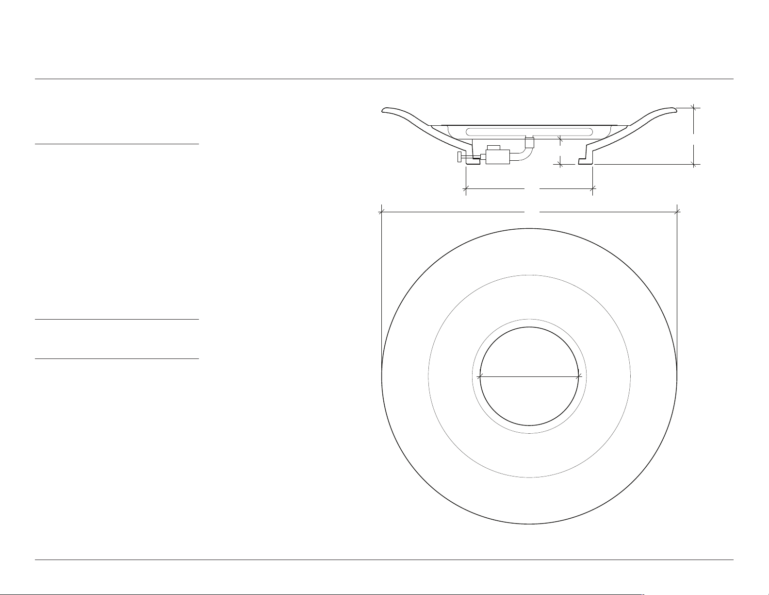
POSITIONING GAS SUPPLY
See page 8 of this manual for Gas
Installation Requirements
The Dish Firebowl has an open base
through which you can bring a gas or
propane line. See Fig. 1.
Please make sure that the gas line is
located only within this area. This will
ensure that the nal position of the
unit will not be compromised.
We recommend that gas risers be
kept as low to grade as possible and
no higher than 3” at their highest
points.
DISH FIREBOWL | Owner and Installation Manual
8”
3 1/2”
18”
42”
3
Air gaps may be used to route
surface-mounted propane hoses.
ATTENTION:
Gas line must be installed by a
licensed contractor in compliance
with local codes.
FIG 1. PLAN AND VERTICAL SECTION
14"
14”
BASE OPENING
Page 4

4
DISH FIREBOWL | Owner and Installation Manual
PLACEMENT AND ASSEMBLY
CAUTION:
HEAVY: Use care
when lifting and
placing to avoid
injury and damage
to property and the
re pit itself. Fire pits
may require 2 or more
people to lift.
ATTENTION: Fragile! Cast concrete will chip if collided with other hard
materials such as stone, metal, or other concrete. HANDLE WITH CARE!
1. Please refer to ‘Clearances to Combustibles’ guide on page 6 of this guide for placement.
2. Ensure that the nal location for the re pit is as at and level as possible. Also provide adequate drainage
beneath the opening in the base of the re pit vessel. Do not block the air/drain gaps (7)
3. Completely unpack the re pit. Some components may be packed inside the Dish body.
4. Remove Burner Assembly (1) and Topping Ring (3) from re pit vessel and carefully set aside.
5. Carefully lift the re pit and place it in its nal position. If there is a gas riser, re pit vessel should be placed
so that the stub is enclosed within the Dish Body (4). If you are using a surface mounted propane hose, feed
it through one of the air gaps (7).
6. If the Dish Body does not sit level, shim appropriately so that it is level and evenly supported.
7. Connect to Natural Gas or Propane Source as per page 8 of this manual.
8. Assemble Burner as per instructions on page 7.
9. Check for leaks and test burner (see page 8)
10. Place Topping Ring (3) back into Body (4). Remove Control Knob (6) and stem from valve assembly. Align
valve with Control Port (5). Place Burner Assembly (1) into Topping Ring.
11. Push Control Knob (6) back into valve.
12. Cover Topping Ring with lava rock following instructions on page 7.
Page 5

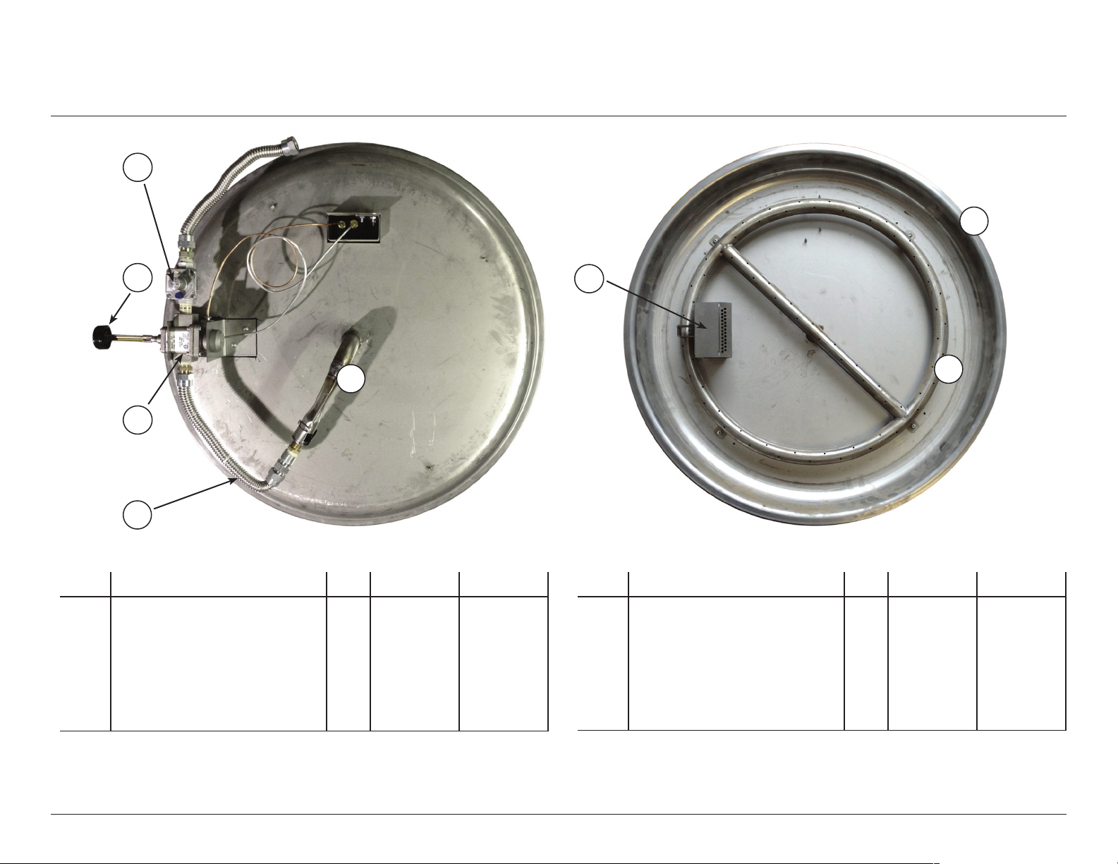
COMPONENTS
1. Burner Assembly
DISH FIREBOWL | Owner and Installation Manual
9. Main Test Point
5
2. Valve Assembly
3. Topping Ring
4. Body
5. Control Port
6. Control Knob
8. Flex Hose/Gas Connection
7. Air/drain gap
FIG 2. DISH - EXPLODED VIEW
Page 6

6
DISH FIREBOWL | Owner and Installation Manual
CLEARANCE TO COMBUSTIBLES
72”
FIG 3. MINIMUM CLEARANCES TO COMBUSTIBLES
12”
Page 7
BURNER ASSEMBLY
DISH FIREBOWL | Owner and Installation Manual
7
WARNING:
Failure to position parts in
accordance with these diagrams
and instructions and/or failure to
use parts specically approved for
use with this appliance may result in
property damage or personal injur y.
CAUTION:
Do not remove the metal data
plates attached to the Outdoor Fire
Pit Burner. These plates contain
important information.
NOTICE:
Installation and repair should be
done by a qualied service person.
The appliance should be inspected
before use and at least once annually
by a qualied service person. More
frequent cleaning may be required
as necessary. It is imperative that
control compartment, burner and
circulating air passageways of the
appliance be kept clean.
TO ASSEMBLE THE BURNER
1. Remove the Burner Assembly and Burner Media
(lava rock) from packaging (see Parts List on pg 15).
2. Connect the Burner Assembly to the gas/propane
supply using the supplied ex connector and
following the instructions on page 8.
3. Carefully leak test all connections following the
procedure on page 8.
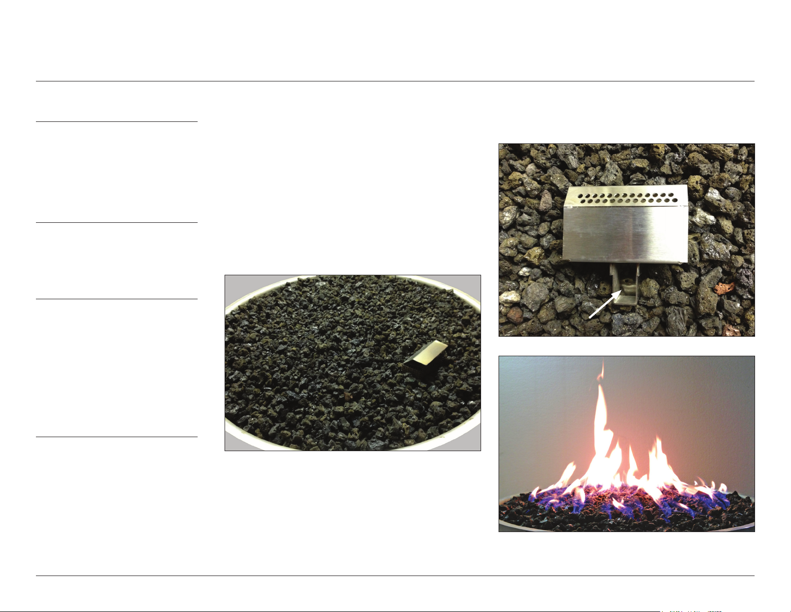
4. Fill the burner pan evenly with burner media covering
burner ring. Media should be level with the top rim of
the pan. Do not obstruct lighting port with burner
media!
7. Place and evenly distribute remaining lava rock on
top of burner and topping ring. Keep the lighting
port open and free of media.
LIGHTING PORT
5. Carefully lift the burner and place it in its housing.
(See page 4)
6. Follow the Initial Lighting Instructions on page 10.
Make sure that the ame carries to all parts of
the burner. Turn OFF the appliance and let it cool
before proceeding to the next step.
Page 8
8
DISH FIREBOWL | Owner and Installation Manual
WARNING:
INSTALLATION REQUIREMENTS
CONNECTING TO GAS SUPPLY
CHECKING GAS CONNECTION
A qualied service person must
connect the appliance to the gas
supply. Follow all local codes.
CAUTION:
Use only new black iron or steel pipe.
Internally tinned copper tubing may be
used in certain areas. Use pipe of 1/2”
diameter or greater to allow proper
gas volume to Outdoor Fire Pit Burner.
If pipe is too small, undue loss of
pressure will occur.
INSTALLATION ITEMS NEEDED:
Before installing the Outdoor
Fire Pit, make sure you have all items
listed bellow:
• piping (check local codes)
• sealant
• manual shutoff valve
• adjustable (crescent) wrench or pliers
• sediment trap
• tee joints
• pipe wrench
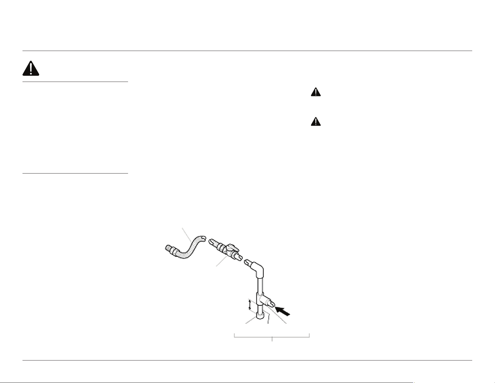
Installation must include a manual shutoff valve, union,
and plugged 1/8” NPT tap. Locate NPT tap within reach
for test gauge hook up. NPT tap must be upstream from
the appliance.
Apply pipe joint sealant lightly to male threads. This will
prevent excess sealant from going into pipe. Excess
sealant in pipe could result in a clogged burner injector.
Install sediment trap in supply line as shown below.
Locate sediment trap where it is within reach for cleaning
and trapped matter is not likely to freeze.
A sediment trap prevents moisture and contaminants
from entering the Outdoor Fire Pit controls. If a sediment
trap is not installed, or is installed incorrectly, the unit may
not work properly.
APPROVED FLEXIBLE GAS HOSE
A.G.A DESIGN-CERTIFIED MANUAL
SHUTOFF VALVE WITH 1/8” NPT TAP
WARNING: Test all gas piping and connections
for leaks after installing or servicing. Correct all leaks
immediately.
WARNING: Never use an open ame to check
for a leak. Apply a mixture of liquid soap and water
to all joints. Bubbles forming on joints while the
gas is running indicate a leak. Correct all leaks at
immediately.
Test Pressures in Excess Of 1/2 psi (3.5 kPa)
This appliance and its individual shutoff valve must be
disconnected from the gas supply piping system during
any pressure testing of that system at test pressures in
excess of ½ psi (3.5 kPa).
Test Pressures Equal To or Less Than 1/2 psi (3.5 kPa)
This appliance must be isolated from the gas supply
piping system by closing its individual manual shutoff
valve during any pressure testing of the gas supply piping
system at test pressures equal to or less than ½ psi (3.5
kPa).
3” MINIMUM
CAP PIPE NIPPLE TEE JOINT
FROM GAS METER (5” W.C.
TO 10.5” W.C. PRESSURE)
SEDIMENT TRAP
Page 9

25"
TECHNICAL DATA
Burner Dimensions
18"
DISH FIREBOWL | Owner and Installation Manual
6"
9
Burner Speci cations
MODEL # MAX INPUT
CIR-18 70,000 4.5” W.C. 10.5” W.C. 3.5” W.C. 18 68 1/8”
CIR-18P 70,000 11.0” W.C. 13.0” W.C. 7.5” W.C. 37 68 1/8”
BTU/Hr
PRESSURE MIN
Minimum Clearances to Combustible Materials:
ABOVE SIDE BELOW
72” 18” 0”
INLET
INLET
PRESSURE MAX
MANIFOLD
PRESSURE
ORIFICE SIZE BURNER PORTS PORT SIZE
Page 10
10
DISH FIREBOWL | Owner and Installation Manual
WARNINGS:
LIGHTING YOUR FIRE PIT
Failure to follow these instructions exactly may result
in re or explosion causing property damage, personal
injury or loss of life.
Before operating the appliance, check all around the
appliance area and on the surrounding oor for the smell
of gas - some gas is heavier than air and may settle on the
oor in the event of a leak. IF YOU SMELL GAS, follow the
safety instructions on page 1 of this manual.
The main gas valve in this appliance is not serviceable. Do
not try to repair or modify the valve, as doing so may result
in a re or explosion. Call a qualied service technician if
you have any safety concerns.
Do not use this appliance if any part of it has been under
water. Immediately call a qualied service technician to
inspect the appliance and to replace any part of the control
system and any gas control that has been under water.
Improper installation, adjustment, alteration, service or
maintenance can result in injury or property damage. For
assistance or additional information, consult a qualied
installer, service agency or the gas supplier.
INITIAL LIGHTING INSTRUCTIONS
1. Purge air from the supply line as follows:
• Open the main shutoff valve.
• Unscrew the main pressure test point.
• Leave the inlet test screw open until gas ows in.
• When the gas is owing, tighten the inlet screw immediately.
2. Test for leaks in each of the following locations:
• The gas supply line connection to the main valve;
• The Burner connections and pilot;
• All joints on the valve and control body;
• All eld made joints and gas shutoff valves;
• All factory made joints and connections.
3. You may check for gas leaks using one of the following methods only:
• Soap and water solution. WARNING: If using a soap and water solution to
test for leaks, DO NOT spray the solution onto electronic parts;
• An approved leak testing spray;
• An electronic sniffer. NOTE: Remove any excess pipe compound from
connections if using this method, as the compound can set off electronic sniffers.
Do not store or use gasoline or other ammable vapors or
liquids in the vicinity of this appliance.
DANGER: NEVER USE AN OPEN FLAME TO CHECK FOR GAS LEAKS.
Page 11
LIGHTING YOUR FIRE PIT
DISH FIREBOWL | Owner and Installation Manual
11
STOP!
Read the safety information on
pages 1, 2 and 8 of this manual.
OPERATING INSTRUCTIONS
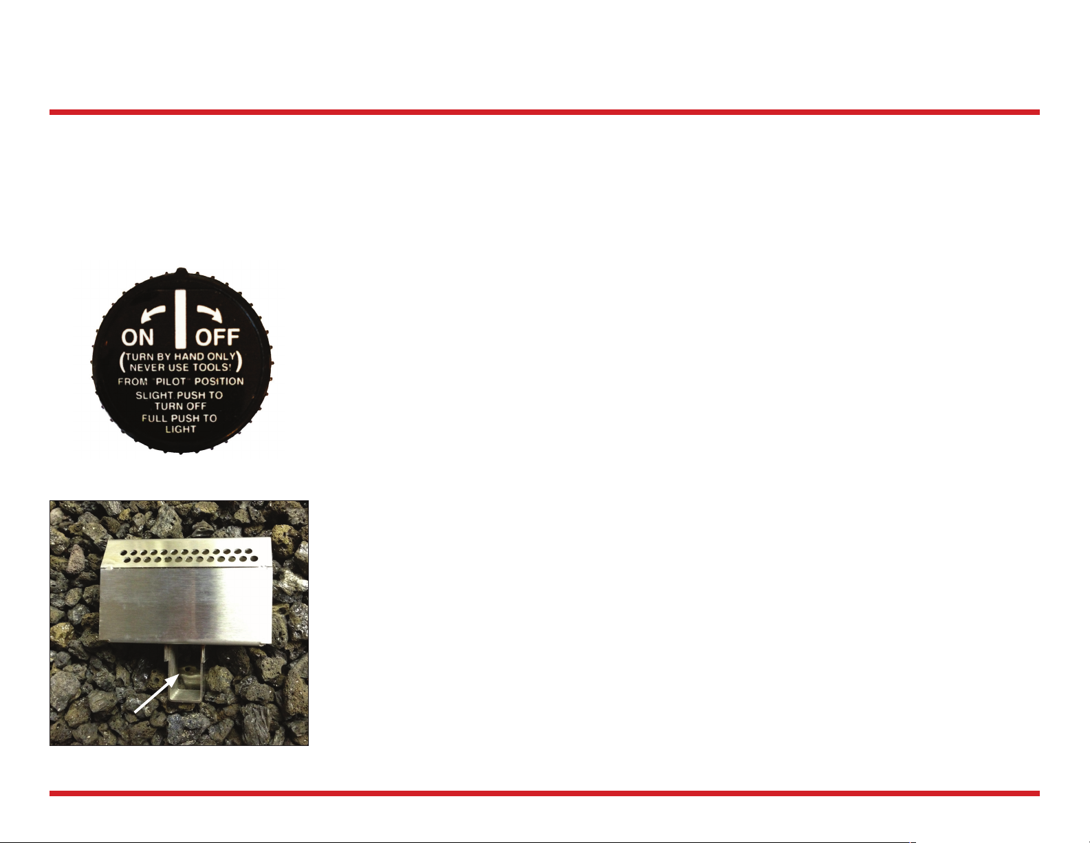
Use only your hand to push in or turn the gas control knob. Never use tools. If the knob will
not push in or turn by hand, don’t try to repair it, call a qualied service technician. Force or
attempted repair may result in a re or explosion.
1. Turn the gas control knob to the OFF position (it will be necessary to depress the knob slightly
at the PILOT position). Allow ve minutes for any gas in the vicinity to dissipate. (LP gas, which
is heavier than air, may require forced ventilation).
2. Turn the gas control knob to the PILOT position.
3. Push down on the gas control knob and light the pilot immediately by applying a ame to the
lighting port. Hold the knob down for one full minute after lighting the pilot.
4. When the gas control knob is released, the pilot ame should continue to burn (if the pilot
goes out, repeat the above steps).
5. Rotate the gas control knob from PILOT to ON position (full counterclockwise position) to
supply full ow to main burner.
NOTE: Not turning the gas control knob to the full ON position will reduce the ow and could
result in poor ignition of main burner.
6. To extinguish main burner, rotate the gas control knob clockwise to the PILOT position.
7. To extinguish pilot, depress control knob slightly and turn to the OFF position (fully clockwise).
LIGHTING PORT
Page 12

12
DISH FIREBOWL | Owner and Installation Manual
WARNING: Turn off gas before servicing re pit. It is recommended that
a quali ed service technician perform these check-ups at the beginning
of each re pit season.
If any irregularities are apparent with operation. Please refer to Troubleshooting
guide, pages 13-14.
BURNER ELEMENT AND PILOT
Keep the burner and pilot area clean by vacuuming or brushing at least twice a year.
Make sure the burner porting and burner air openings are free of obstructions at all
times.
Inspect area around the burner. Remove any lint or foreign material with a brush or
vacuum cleaner.
CLEANING AND MAINTENANCE
Pilot Assembly
The burner must be replaced prior to the appliance being put into operation if it
evident that the burner is damaged.
PILOT FLAME
The ames from the pilot should be
visually checked as soon as the unit is
installed, and periodically during normal
operation. The pilot ame must always be
present when the re pit is in operation.
The pilot ame has two distinct ames:
one engul ng the ame sensor, and the
other reaching to the main burner.
Burner Element
Page 13
TROUBLESHOOTING
DISH FIREBOWL | Owner and Installation Manual
13
WARNING:
Turn off appliance and let cool before
servicing. Only a qualied service
person should service and repair this
appliance.
IMPORTANT: Operating unit where
impurities in air exist may create
odors. Cleaning supplies, paint,
paint remover, cigarette smoke,
cements and glues, new carpet or
textiles, etc., create fumes. These
fumes may mix with combustion
air and create odors. These odors
will disappear over time.
OBSERVED PROBLEM POSSIBLE CAUSE REMEDY
Unit is smoking / sooting excessively.
(Note: It is natural and unavoidable for
appliance sets to produce moderate
levels of carbon (soot) where ames
contact the media.)
Burner is excessively noisy
(Note: The movement and combustion
of gas will create low, unavoidable
levels of noise.)
Gas odor even when manual valve is in
the OFF position
Unit produces unwanted odors 1. Gas leak. See Warning statement
IF YOU SMELL GAS:
1. Poor fuel quality
2. Excessive ame impingement or
blockage
3. Improper fuel/air mixture
1. Passage of air/gas across irregular
surfaces
2. Excessive gas pressure on natural
gas units
1. Gas leak. See Warning statement
below.
2. Main gas valve defective.
below.
1. Contact local natural gas
company
2. Separate the stones to allow
more ame passage
3. Remove any foreign items from
the ame pattern and/or check
for proper orice sizing
1. Relieve any tight bends or kinks
in gas supply line
2. Check/reset gas regulator
pressure
1. Locate and correct all leaks (see
Checking Gas Connections, pg 5)
2. Replace gas valve
1. Locate and correct all leaks (see
Checking Gas Connections, pg 5)
Shut off gas supply.
Do not try to light any appliance.
Do not touch any electrical switch; do not use any phone in the vicinity of the appliance.
Immediately call your gas supplier from a safe distance. Follow your gas supplier’s instructions.
Page 14

14
DISH FIREBOWL | Owner and Installation Manual
TROUBLESHOOTING cont’d
WARNING:
Turn off appliance and let cool before
servicing. Only a qualied service
person should service and repair this
appliance.
OBSERVED PROBLEM POSSIBLE CAUSE REMEDY
Pilot cannot be lit 1. Gas supply turned off or manual
shutoff valve closed
2. Air in gas lines when installed
3. Pilot adjustment screw closed
4. Pilot is clogged
Burner does not light after pilot is lit 1. Burner orice is clogged
2. Inlet gas pressure is too low
3. Burner orice diameter is too small
4. Flame sensor lead loose or
disconnected
Delayed burner ignition 1. Pilot ame needs adjusting 1. Adjust pilot for approximately 1”
Burner ame is too low 1. Incorrect gas supply or pressure
2. Blocked burner orice or burner
ports
3. Improper burner orice size
1. Turn off gas supply or open
manual shutoff valve
2. Purge air from the supply line
3. Adjust pilot ame for approximately 1” blue ame
4. Clean pilot (see Cleaning and
Maintenance, page 12) or replace
pilot assembly
1. Clean burner orice
2. Contact local gas or propane
supplier
3. Replace burner orice
4. Reconnect or tighten lead
blue ame
1. Check for proper gas supply
pressure
2. Free burner orice and burner
ports of any burrs, paint, or other
blockage
3. Verify proper burner orice sizing
(see page 9)
Page 15
ILLUSTRATED PARTS LIST
13
DISH FIREBOWL | Owner and Installation Manual
2
15
10b
3
10
9
BOTTOM TOP
KEY # DESCRIPTION QTY CIR-18 CIR-18P
1
2
3
4
5
6
7
8
9
Burner Assembly
Burner Pan
Venturi
Orice
Lock Nut
3/8” FPT x 1/2” MFL Connector
3/8” MPT x 1/2” MFL Connector
3/8” Nipple Close
1/2” Flex Connector 10”
1
1
1
1
1
1
2
1
2
RBP018
PAN025
VNG017
O33018
LN111C
CO488C
CO468C
CO112C
FC4810
RBP018
PAN025
VLP017
O33037
LN111C
CO488C
CO468C
CO112C
FC4810
12
1
KEY # DESCRIPTION QTY CIR-18 CIR-18P
10
10b
11
12
13
14
15
16
Main Valve
Control Knob
Pilot Assembly
Pilot Shield
Regulator
Valve Bracket Set (2 pieces)
Burner Media - Glass (NG only)
Burner Media - Lava Rock (LP only)
1
1
1
1
1
1
1
VAE764
PNA388
EPC011
RNG20L
BRE764
GC3C18
VAE764
PLP388
EPC011
RLP20L
BRE764
LA3C18
WARNING:
Failure to position parts in accordance with diagrams or failure to use parts specically approved for this appliance may result in property damage or personal injury.
REPLACEMENT PARTS ARE AVAILABLE THROUGH THE MANUFACTURER
Page 16

16
DISH FIREBOWL | Owner and Installation Manual
ILLUSTRATED PARTS LIST cont’d
8
6
10
13
9
14 4
15
11
12
5
3
16
Page 17

NOTES
DISH FIREBOWL | Owner and Installation Manual
17
Page 18

18
DISH FIREBOWL | Owner and Installation Manual
WARRANTY INFORMATION
KEEP THIS FOR WARRANTY
MODEL: (circle one) CIR-18
CI R-18 P
SERIAL NO:
DATE PU RCHA S E D:
OUTDOOR FIRE PIT BURNER: LIMITED LIFETIME WARRANTY
The following components are warranted for life to the original owner, subject to proof of purchase:
BURNER 18 - Outdoor Fire Pit Burner - manufactured by Hevi Manufacturing Inc.
BASIC WARRANTY
Hevi Manufacturing Inc. warrants the components and materials in your appliance to be free from manufacturing
and material defects for a period of one year from date of installation. After installation, if any of the components
manufactured by Hevi Manufacturing Inc. in the appliance are found to be defective in materials or workmanship,
Hevi Manufacturing Inc. will, at its option, replace or repair the defective components at no charge to the original
owner. Hevi Manufacturing Inc. will also pay for reasonable labor cost incurred in replacing or repairing such
components for a period of one year from date of installation. Any products presented for warranty repair must be
accompanied by a dated proof of purchase.
This Limited Lifetime Warranty will be void if the appliance is not installed by a qualied installer in accordance
with installation instructions. The Limited Lifetime Warranty will also be void if the appliance is not operated and
maintained according to the operating instructions supplied with the appliance, and does not extend to (1) re pit
burner assembly damaged by accident, neglect, misuse, abuse, alterations, negligence of others, including the
installation thereof by unqualied installers, (2) the costs of removal, reinstallation or transportation of defective
parts on the appliance, or (3) incidental or consequential damage. All service work must be performed by an
authorized service representative.
This warranty is expressly in lieu of other warranties, express or implied, including the warranty of merchantability
of tness for purpose and of all other obligations or liabilities. Hevi Manufacturing Inc. does not assume for it any
other obligations or liabilities in connection with sale or use of the appliance. In states that do not allow limitations
on how long an implied warranty lasts, or do not allow exclusion of indirect damage, those limitations of exclusions
may not apply to you. You may also have additional right not covered in the Limited Lifetime Warranty. Hevi
Manufacturing Inc. reserves the right to investigate any and all the claims against this Warranty and decide upon
method of settlement. For information about this warranty contact:
Hevi Manufacturing Inc
7650 Kimbel Street
Units 22-27
Mississauga ON L6S 1B1
Canada
 Loading...