

Intertek A/GPD1424 Series, A/GPD1437 Series, A/GPD1436 Series, A/GPD1430 Series, A/GPD1448 Series Installation Instructions Manual
...Page 1

I
NSTALLATION INSTRUCTIONS
A/GPD 14 SEER “M” SERIES - S
D
UAL FUEL GAS-ELECTRIC HEATING
Affix this manual and Users Information Manual
adjacent to the unit.
& C
OOLING UNITS
INGLE PACKAGE
ATTENTION INSTALLING PERSONNEL
Prior to installation, thoroughly familiarize yourself with this
Installation Manual. Observe all safety warnings. During installation or repair, caution is to be observed.
It is your responsibility to install the product safely and to educate the customer on its safe use.
RECOGNIZE THIS SYMBOL
AS A SAFETY PRECAUTION.
These installation instructions cover the outdoor installation
of single package gas electric heating and cooling units. See
the Specification Sheet applicable to your model* for
information regarding accessories.
*NOTE: Please contact your distributor or our website for
the applicable Specifications Sheets referred to in this manual.
This Forced Air Central Unit Design Complies With R equirements
Embodied in The American National Standard / National
Standard of Canada Shown Below.
ANSI Z21.47•CSA-2.3 Central F urnaces
*NOTE: Please contact your distributor or our website for
the applicable Specification Sheet referred to in this manual.
IO-407K
07/2018
is a registered trademark of Maytag Corporation or its related companies and is used under license. All rights reserved.
Goodman Manufacturing Company , L.P.
5151 San Felipe, Suite 500, Houston, TX 77056
www.goodmanmfg.com or www .amana-hac.com
© 2011-2018 Goodman Manufacturing Company, L.P.
O
NLY PERSONNEL THAT HAVE BEEN TRAINED TO INSTALL, ADJUST, SERVICE OR
REPAIR (HEREINAFTER
SHOULD SERVICE THE EQUIPMENT
FOR ANY INJURY OR PROPERTY DAMAGE ARISING FROM IMPROPER SERVICE OR
SERVICE PROCEDURES
FOR ANY INJURY OR PROPERTY DAMAGE WHICH MAY RESULT
JURISDICTIONS THAT REQUIRE ONE OR MORE LICENSES TO SERVICE THE EQUIPMENT
SPECIFIED IN THIS MANUAL, ONLY LICENSED PERSONNEL SHOULD SERVICE THE
EQUIPMENT
THE EQUIPMENT SPECIFIED IN THIS MANUAL, OR ATTEMPTING TO INSTALL, ADJUST
SERVICE OR REPAIR THE EQUIPMENT SPECIFIED IN THIS MANUAL WITHOUT PROPER
TRAINING MAY RESULT IN PRODUCT DAMAGE, PROPERTY DAMAGE, PERSONAL
INJURY OR DEATH
, “
SERVICE
”)
THE EQUIPMENT SPECIFIED IN THIS MANUAL
. THE
MANUFACTURER WILL NOT BE RESPONSIBLE
. IF
YOU SERVICE THIS UNIT, YOU ASSUME RESPONSIBILITY
. IN
ADDITION, IN
. I
MPROPER INSTALLATION, ADJUSTMENT, SERVICING OR REPAIR OF
.
WARNING
Cancer and Reproductive Harmwww.P65Warnings.ca.gov.
,
Page 2

INDEX (continued)
INDEX
TO THE INSTALLER ..................................................... 2
TO THE OWNER ......................................................... 2
SHIPPING INSPECTION ................................................. 2
SAFETY INSTRUCTIONS ................................................ 2
ORDERING PARTS ....................................................... 5
CODES AND REGULATIONS............................................. 5
EPA REGULATIONS ...................................................... 5
NATIONAL CODES ....................................................... 5
PRE-INSTALLATION CHECKS ........................................... 6
UNIT INSTALLATION .................................................... 6
A
LL INSTALLATIONS .............................................. 6
G
ROUND LEVEL INSTALLATIONS ONLY .............................. 6
R
OOFTOP INSTALLATIONS ONLY .................................... 7
ROOF CURB INSTALLATIONS ONLY ................................. 7
GENERAL INFORMATION ............................................... 7
RIGGING DET AILS ........................................................ 8
GAS PIPING .............................................................. 8
H
IGH ALTITUDE DERATE (U.S. INSTALLATIONS ONLY) .............. 8
P
IPING ......................................................... 8
WIRING .....................................................11
H
IGH VOLTAGE WIRING .......................................11
THERMOSTAT CONTROLS ........................................11
L
OW VOLTAGE WIRING ........................................11
I
NTERNAL WIRING ..............................................11
CIRCULA TING AIR AND FIL TERS .....................................12
A
IRFLOW CONVERSION .........................................12
H
ORIZONTAL AIR FLOW .........................................12
D
UCTWORK ....................................................12
F
ILTERS .......................................................13
VENTING ..............................................................13
I
NSTALLATION - FLUE HOOD EXHAUST.............................13
I
NSTALLATION - COMBUSTION AIR INTAKE HOOD....................13
CONDENSATE DRAIN ...................................................14
CONDENSA TE DRAIN CONNECTION.................................14
NORMAL SEQUENCES OF OPERATION ..............................14
HEAT PUMP OPERATION ..............................................14
O
UTDOOR THERMOSTAT .........................................14
O
PTIONAL OUTDOOR THERMOSTAT (OTDFPKG-01) .............1 4
H
EATING CYCLE (HEAT PUMP) ..................................1 4
H
EATING CYCLE (NATURAL GAS/ LP)...........................14
DEFROST CYCLE ...............................................15
C
OOLING ......................................................15
F
AN ONLY ....................................................15
A
IR FLOW MEASUREMENT AND ADJUSTMENT .......................15
AIR FLOW ADJUSTMENTS FOR INDOOR BLOWER MOTOR ............15
START-UP, ADJUSTMENTS, AND CHECKS ............................16
H
EATING START-UP ( NATURAL GAS / LP) ......................16
C
OOLING START-UP .............................................19
MAINTENANCE..........................................................19
F
IL TER REPLACEMENT OR CLEANING...............................19
C
ABINET FINISH MAINTENANCE ..................................19
C
LEAN OUTSIDE COIL (QUALIFIED SERVICER ONLY)...............19
CONDENSER, EVAPORATOR, AND INDUCED DRAFT MOTORS .........19
F
LAME SENSOR (QUALIFIED SERVICER ONLY) ......................19
M
AIN BURNER FLAME (QUALIFIED SERVICER ONLY) ...............20
APPENDIX ..............................................................21
TROUBLESHOOTING...................................................22
I
GNITION CONTROL DIAGNOSTIC INDICATOR CHART .................23
H
EATING TIMING CHART ........................................23
C
OOLING/HEA T PUMP TIMING CHART .............................23
UNIT DIMENSIONS ..............................................24
WIRING DIAGRAM ......................................................25
M
INIMUM CLEARANCES ..........................................27
R
ECOMMENDED FILTER SIZES .....................................27
BLOWER PERFORMANCE DATA ....................................29
START-UP CHECKLIST .................................................. 32
TO THE INSTALLER
Before installing this unit, please read this manual to familiarize yourself on the specific items which must be adhered to,
including maximum external static pressure to unit, air temperature rise, minimum or maximum CFM and motor speed connections.
IMPORTANT NOTE: If a crankcase heater is used, the unit should be energized 24 hours prior to compressor start up to ensure
crankcase heater has sufficiently warmed the compressor. Compressor damage may occur if this step is not followed.
TO THE OWNER
A warranty certificate is provided with the unit. Read the warranty carefully and note what is covered. Keep the warranty
certificate in a safe place so you can find it when necessary.
SHIPPING INSPECTION
Upon receiving the unit, inspect it for damage from shipment. Claims for damage, either shipping or concealed, should be filed
immediately with the shipping company. Check the unit model number, specifications, electrical characteristics and accessories to
determine if they are correct. In the event an incorrect unit is shipped, it must be returned to the supplier and must NOT be
installed. The manufacturer assumes no responsibility for installation of incorrectly shipped units.
SAFETY INSTRUCTIONS
The following symbols and labels are used throughout this manual to indicate immediate or potential safety hazards. It is the
owner’s and installer’s responsibility to read and comply with all safety information and instructions accompanying these symbols.
Failure to heed safety information increases the risk of personal injury, property damage, and/or product damage.
2
Page 3

FIRE OR EX P LOSION HAZARD
Failure to fo l low the saf ety warnings ex actl y could re sult in
serious injury, death or property damage. Never test for
gas leaks with an open flame. Use a commercially available
soap so lution m a d e sp ecific a lly fo r t h e d etectio n o f le aks
to check all connections. A fire or explosion may resul t
causing property damage, personal injury or
loss of life.
AVERTISSEMENT
RISQUE D'INCENDIE OU D'EXPLOSION
Si les consignes de sécurité ne sont pas suivies à la
lettre, cela peut en tr aî ner la mort, de grav es bles sure s
ou des dommages matériels. Ne ja mai s vérifier la
présence de fuites de g az au moyen d'une flamme nue.
Vérifier tous les r accor ds en uti lisant une s olution
savonneuse commerciale conçue spécialement pour la
détection de fuites. Un incendie ou une explosion
risque de se produire, ce qui
peut entraîner la mort,
des blessures ou des dommages matériels.
3
Page 4
AVERTISSEMENT
CARBON MONOXIDE POISONING HAZARD
Failure to follow the steps outlined below for each
appliance connected to the venting sy stem being
placed into operati on could re s ul t in carbon mon oxi de
poisoning or death.
The following steps sha ll be followed for each appliance
connected to the venting system being placed into
operation, while all other appliances connected to the
venting sy s tem are not in operation:
1) Seal any unused openings in the venting system.
2) Inspect the venting system for pr ope r siz e and
horizontal pitch, as requir ed in the National Fuel Gas
Code, ANSI Z223.1/NFPA 54 or the Natural Gas and
Propane Installation Code, CSA B149.1 and these
instru ctions. Determine tha t t here is n o bl o ckage o r
restriction, leakage, cor r osion and other deficiencies
which could cause an unsafe co ndi tion.
3) As far as practical, close all building doors and
windows and all doors between the space in which the
appliance(s) connected t o the v enting system are
located and other spaces of the building.
4) Close fireplac e da mpe rs.
5) Turn on clothes dryers and any appliance not
connected to the venting system. Turn on any exhaust
fans, such as range hoods and bathroom exhausts, so
they are operating at maximum speed. Do not operate
a summer exhaust fan.
6) Follow the lighting instructions. Place the appliance
being inspected into operation. Adjust the thermostat
so app lia nce is op erating cont inuous ly.
7) T est for spillage from draft hood equipped
appliances at the draft hood relief opening after 5
minutes of main burner operation. Use the flame of a
match or candle.
8) If improper venting is observ ed during any of the
above tests, the venting system must be corrected in
accordance with the National Fuel Gas Code, ANSI
Z223.1/NFPA 54 and/or Natural Gas and Propane
Installation Code, CSA B149.1.
9) After it has been determined that eac h app liance
connected to the venting system properly vents when
tested as outlined above, return doors, windows,
exhaust fans, firepl ace dampers and any other gas-fired
burning appliance to their previous conditions of use.
RISQUE D'INTOXICA TION AU MONOXYDE DE
Si
CARBONE
les étapes décrites ci-dessou s n e sont pas
suivies pour chacun des a p pa reils raccordés a u système
de ventilation au moment de sa mise en marche, cela
peut entraîner une intoxication au monoxyde de
carbone ou la mort. Les étapes suivantes doivent être
suivies pour chacun des a p pa reils raccordés a u système
de ventilation au moment de sa mise en marche, alors
que tous les autres appareils r accordés au sys tèm e de
ventilation ne sont pas en marc he :
1) Sceller toutes les ouver tures inutilisées du sy s tème de
ventilation.
2) Inspecte r le système de ventilation a fin de vérifier si
la taille et l'i n cl in a ison par rapport à l'horizontale so nt
conformes aux exigences du National Fuel Gas Code,
ANSI Z223.1/NFPA 54 ou du Code d'installation du gaz
naturel et du propane, CSA B 149.1 et à ces instructions.
Vérifier qu'il n'y a pas d'obstruction ou de res triction, de
fuite, de corrosion et d'autres pr obl èmes qui pourr aient
entraîner une situation dang er euse.
3) Si possible, fermer toutes les portes et fenêtre s du
bâtiment ainsi que toutes les portes séparant l'endroit
où se trouvent les appareils raccordés au système de
ventilation et les autres zones du bâtiment.
4) Fermer le regist re de s foyers.
5) Mettre les sécheuses en marche ainsi que tous les
autres appareils qui ne sont pas raccordés au sy s tème
de ventilation. Met tr e en ma r che tous les ventilateurs
de tirage, comme celui des hottes de cuisine et des
salle s de bains, et les régler à la puissance m axima le. Ne
pas mettre en marche le s ventilateurs d'été.
6) Suivre les in st ru ctions d'allumage. Mett re en marche
l'appareil soumis à l'inspection. Régler le thermostat de
manière à ce que l'appareil fonctionne en continu.
7) Vérifier la présence de fuite au niveau de l'ouverture
du coupe-tirage des appareils qui en sont dotés après 5
minutes de fonctionnement du brûleur principal. Utiliser
la flamme d'une allumette ou d'une bougie.
8) Si un problème de ventilation est observé pendant
l'un des essais décrits ci-dessus, des cor r ec tif s doiven t
être apportés au système de ventilation conformément
au National Fuel Gas Code, ANSI Z223.1/NFP A 54 et (ou)
au Code d'installation du gaz naturel et du propane, CSA
B149.1.
9) Une fois qu'il a été détermi né que chaque
appareil
raccordé au système de ventilation fonctionne
correctement au moyen des essais décr its cidessus, les portes, les fenêtres, les ventilateurs, les
registres de foyer et tous les autres appareils de
combustion alimentés au gaz doivent être remis
dans leur état initial.
4
Page 5
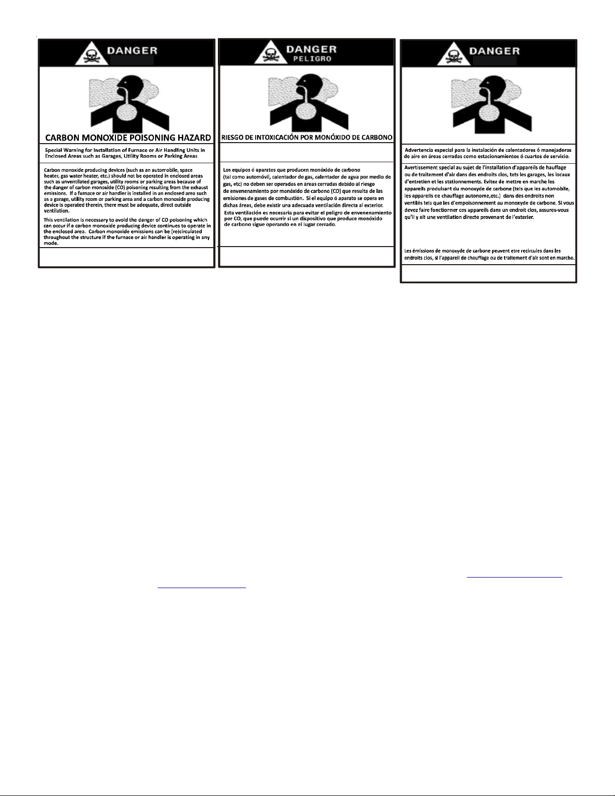
Advertencia especial para la instalación de calentadores ó manejadoras
de aire en áreas cerradas como estacionamientos ó cuartos de servicio.
RISQUE D'EMPOISONNEM ENT A U
MONOXYDE DE CARBONE
Cette venti l ation est nécessaire pour éviter le danger d'intoxicat ion
au CO pouvant survenir si un appareil produisant du monoxyde
de carbone continue de foncti onne r au sein de la zone confinée.
Le monoxyde de
des
dommages permanents au cerveau et meme la mort.
carbone peut causer des maladies graves telles que
B10259-216
CO can cause serious illness including permanent brain
damage or death.
B10259-216
Las emision es de monóx ido de ca rbono pueden circular a tr avés
del aparato cuando se opera en c u alquie r m o do.
El monóxido de carbono puede causar enfermedades severas
com o daño cere b r al perma nente ó mu e rte.
B10259-216
ORDERING PARTS
When reporting shortages or damages, or ordering repair parts,
give the complete model and serial numbers as stamped on the
units nameplate. Replacement parts for this appliance are available through your contractor or local distributor. For the location of
your nearest distributor, consult the white business pages, the yellow page section of the local telephone book or contact:
HOMEOWNER SUPPORT
GOODMAN MANUFACTURING COMPANY, L.P.
19001 KERMIER ROAD
HOUSTON, TEXAS 77484
877-254-4729
CODES AND REGULATIONS
The *PD M-series dual fuel units are designed for OUTDOOR USE ONLY. The *PD is only available in 2 through 4 ton and heating
capacities from 70,000 - 115,000 btu. The units can be easily installed in manufactured or modular homes with existing high-static
duct work. The units can also be easily converted to accommodate a plenum for normal or low-static applications. The *PD M-series
are self contained packaged units so the only connections needed for installation are the supply and return ducts, the line and low
voltage wiring drain connection and appropriate gas piping. Rated performance is achieved after 72 hours of operation. Rated
performance is delivered at the specified airflow. See outdoor unit specification sheet for split system models or product
specification sheet for packaged and light commercial models. Specification sheets can be found at www.goodmanmfg.com for
Goodman® brand products or www.amana-hac.com for Amana® brand products. Within either website, please select the residential
or commercial products menu and then select the submenu for the type of product to be installed, such as air conditioners or
heat pumps, to access a list of product pages that each contain links to that model’s specification sheet.
EPA REGULATIONS
IMPORTANT: THE UNITED STATES ENVIRONMENTAL PROTECTION AGENCY (EPA) HAS ISSUED VARIOUS REGULATIONS REGARDING THE INTRODUCTION AND
DISPOSAL
SUBSTANTIAL
ON
OF REFRIGERANTS IN THIS UNIT. FAILURE TO FOLLOW THESE REGULATIONS MAY HARM THE ENVIRONMENT AND CAN LEAD TO THE IMPOSITION OF
FINES. BECAUSE REGULATIONS MAY VARY DUE TO PASSAGE OF NEW LAWS, WE SUGGEST A CERTIFIED TECHNICIAN PERFORM ANY WORK DONE
THIS UNIT. SHOULD YOU HAVE ANY QUESTIONS PLEASE CONTACT THE LOCAL OFFICE OF THE EPA.
NATIONAL CODES
This product is designed and manufactured to permit installation in accordance with National Codes. It is the installer’s responsibility
to install the product in accordance with National Codes and/or prevailing local codes and regulations.
5
Page 6
PRE-INSTALLATION CHECKS
Before attempting any installation, the following points should be considered:
• Structural strength of supporting members
• Clearances and provision for servicing
• Power supply and wiring
• Air duct connections
• Drain facilities and connections
• Gas piping and connections
• Location may be on any four sides of a home, manufactured
or modular, to minimize noise
UNIT INSTALLATION
A
LL INSTALLATIONS:
• For proper flame pattern within the heat exchanger and proper condensate drainage, the unit must be mounted level.
• The flue outlet hood must be at least 12 inches from any opening through which flue gases could enter a building, and at least
three feet above any forced air inlet located within ten feet. The economizer/manual fresh air intake/motorized fresh air
intake and combustion air inlet mounted on the unit are not affected by this restriction.
• To avoid possible corrosion of the heat exchanger, do not locate the unit in an area where the outdoor air (i.e. combustion
air for the unit) will be frequently contaminated by compounds containing chlorine or fluorine. Common sources of such
compounds include swimming pool chemicals and chlorine bleaches, paint stripper, adhesives, paints, varnishes, sealers,
waxes (which are not yet dried) and solvents used during construction and remodeling. Various commercial and industrial
processes may also be sources of chlorine/fluorine compounds.
• To avoid possible illness or death of the building occupants, do NOT locate outside air intake device (economizer, manual fresh
air intake, motorized fresh air intake) too close to an exhaust outlet, gas vent termination, or plumbing vent outlet. For
specific distances required, consult local codes.
• Allow minimum clearances from the enclosure for fire
protection, proper operation, and service access (see
appendix). These clearances must be permanently
maintained.
• The combustion air inlet and flue outlet hoods on the unit
must never be obstructed. If used, do not allow the
economizer/manual fresh air damper/ motorized fresh air
damper to become blocked by snow or debris. In some
climates or locations, it may be necessary to elevate the
unit to avoid these problems.
• Damper must be in open position when appliance main
burner(s) is operating.
Le registre doit être ouvert lorsque tout brûleur principal
de l’appareil est en état de fonctionnement.
• When the unit is heating, the temperature of the return air
entering the unit must be between 50° F and 100° F.
• Units manufactured on or after May 1, 2017 are not permitted
to be used in Canada for heating of buildings or structures
under construction.
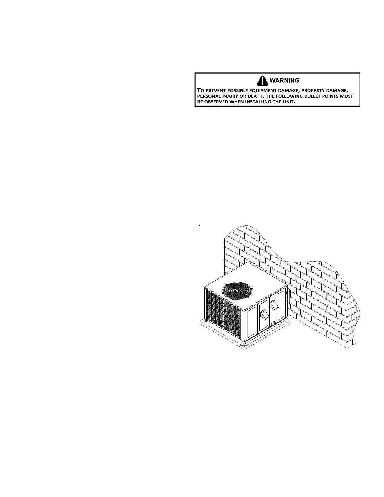
GROUND LEVEL INSTALLATIONS ONLY:
• When the unit is installed on the ground adjacent to the
building, a level concrete (or equal) base is recommended.
Prepare a base that is 3” larger than the package unit
footprint and a minimum of 4” thick.
• The base should also be located where no runoff of water
from higher ground can collect in the unit.
• The top of the unit should be completely unobstructed. If
units are to be located under an overhang, there should be
a minimum of 48” clearance and provisons made to deflect
the warm discharge air out from the overhang.
Outside Slab Installation
6
Page 7
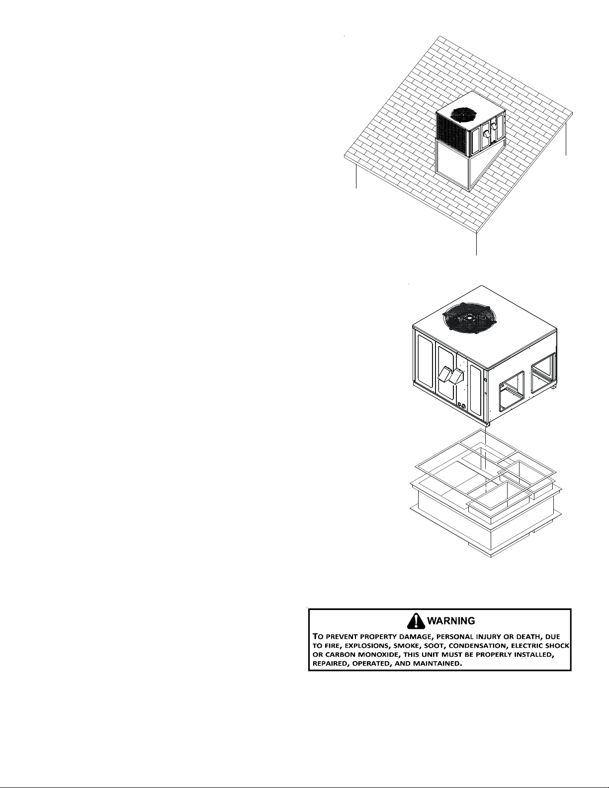
ROOFTOP INSTALLATIONS ONLY:
NOTE: To ensure proper condensate drainage, unit must be installed in
a level position.
• To avoid possible property damage or personal injury, the roof must
have sufficient structural strength to carry the weight of the unit(s)
and snow or water loads as required by local codes. Consult a
structural engineer to determine the weight capabilities of the
roof.
• The unit may be installed directly on wood floors or on Class A,
Class B, or Class C roof covering material.
• To avoid possible personal injury, a safe, flat surface for service
personnel should be provided.
Rooftop Installation
ROOF CURB INSTALLATIONS ONLY:
• Sufficient structural support must be determined prior to locating
and mounting the curb and package unit.
• Ductwork must be constructed using industry guidelines. The duct work must be
placed into the roof curb before mounting the package unit.
• Curb insulation, cant strips, flashing and general roofing material are furnished by
the contractor.
GENERAL INFORMATION
This unit is approved for outdoor installation ONLY. To assure that your unit operates
safely and efficiently, it must be installed, operated, and maintained in accordance with
these installation and operating instructions, all local building codes and ordinances, or
in their absence, with the latest edition of the National Fuel
Gas Code NFPA 54/ANSI Z223.1 and National Standard of Canada
CAN/CSA B149 Installation Codes.
The heating and cooling capacities of the unit should be greater
than or equal to the design heating and cooling loads of the
area to be conditioned. The loads should be calculated by an
approved method or in accordance with A.S.H.R.A.E. Guide or
Manual J - Load Calculations published by the Air Conditioning
Contractors of America.
Obtain from:
American National Standards Institute
25 West 43rd street, 4th Floor
New York, NY 10036
7
Roof Curb Installation
Page 8
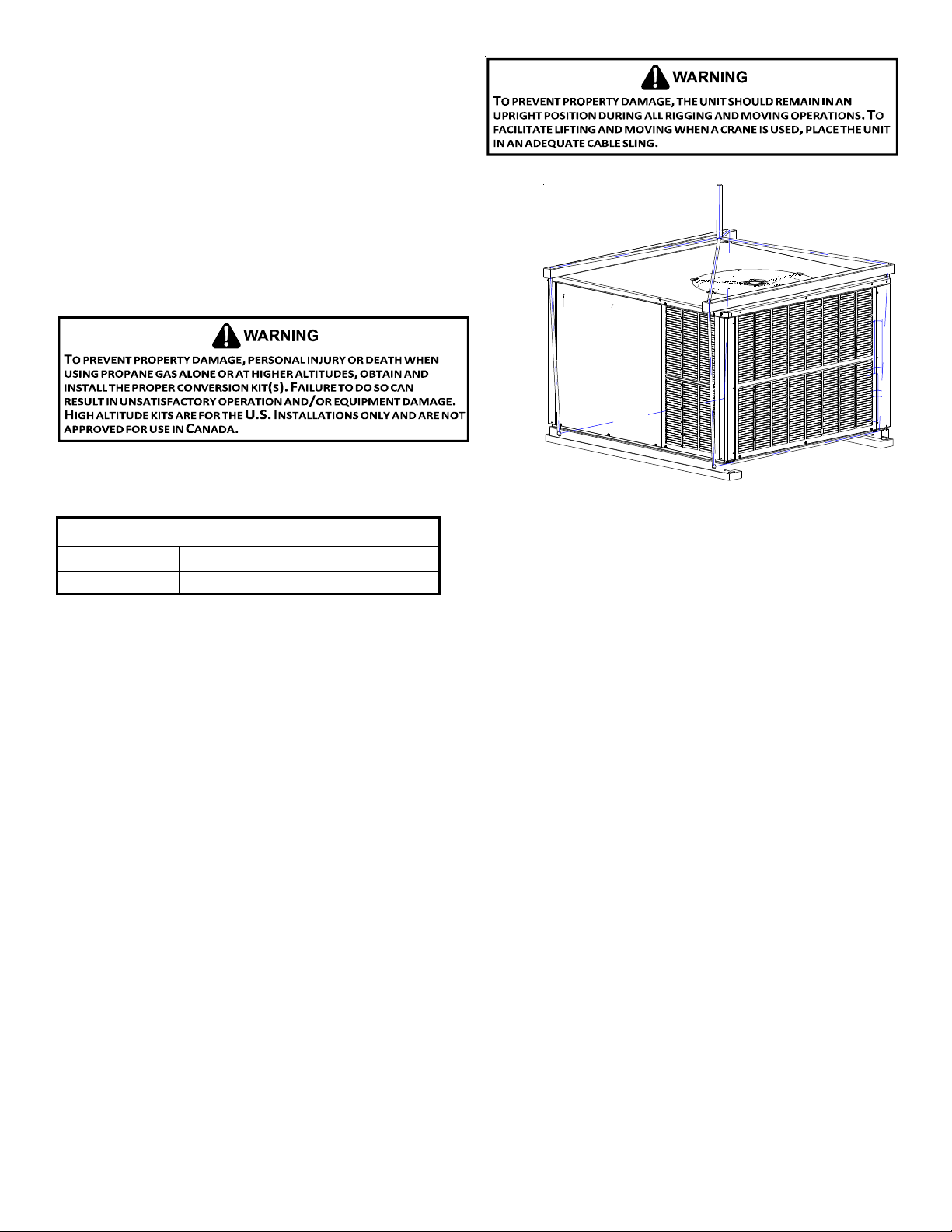
RIGGING DETAILS
Refer to the Unit Installation Instructions for proper unit
installation. Curbing must be installed in compliance with the
National Roofing Contractors Association Manual.
Lower unit carefully onto roof mounting curb. While rigging unit,
center of gravity will cause condenser end to be lower than
supply air end.
GAS PIPING
IMPORTANT NOTE: This unit is factory set to operate on natural gas at
the altitudes shown on the rating plate.
The rating plate is stamped with the model number, type of gas and gas
input rating. Make sure the unit is equipped to operate on the type of
gas available. Conversion to LP gas is permitted with the use of the factory authorized conversion kit LPM-08.
Rigging
INLET GAS PRESSURE
Natural Min. 5.0" W.C., Max. 10.0" W.C.
Propane Min. 11.0" W.C., Max. 13.0" W.C.
Inlet Gas Pressure Must Not Exceed the Maximum Value Shown in Table Above.
The minimum supply pressure should not vary from that shown in the table above because this could prevent the unit from having
dependable ignition. In addition, gas input to the burners must not exceed the rated input shown on the rating plate. Over firing
of the unit could result in premature heat exchanger failure.
HIGH ALTITUDE DERATE (U.S. INSTALLATIONS ONLY)
IMPORTANT NOTE: Installation of this gas/electric package unit at altitudes above 2000 ft (610 m) shall be made in accordance with
the Listed High Altitude Conversion Kit.
L’installation de ce générateur de chaleur à des altitudes supérieures à 2000 pi (610 m) doit être effectuée conformément aux
instructions accompagnant la trousse de conversion pour haute altitude fournie avec cet appareil.
The gas/electric units naturally derate with altitude. Do not attempt to increase the firing rate by changing orifices or increasing
the manifold pressure. This can cause poor combustion and equipment failure. At all altitudes, the manifold pressure must be
within 0.3 inches W.C. of that listed on the nameplate for the fuel used. At all altitudes and with either fuel, the air temperature rise
must be within the range listed on the unit nameplate.
Refer to the Installation Manual provided with the LP kit for conversion from natural gas to propane gas and for altitude adjustments.
Use HA02 for installations above 2000’.
NOTE: Up to 2,000 feet, no changes are required; above 2,000 feet, refer to the gas/electric package unit specification sheets for
required kit(s).
PIPING
IMPORTANT NOTE: To avoid possible unsatisfactory operation or equipment damage due to under firing of equipment, do not
undersize the natural/propane gas piping from the meter/tank to the unit. When sizing a trunk line, include all appliances on that
line that could be operated simultaneously.
The rating plate is stamped with the model number, type of gas and gas input rating. Make sure the unit is equipped to operate on
the type of gas available. The gas line installation must comply with local codes, or in the absence of local codes, with the latest
edition of the National Fuel Gas Code NFPA 54/ANSI Z223.1.
8
Page 9

Natural Gas Connection
Refer to the Proper Piping Practice drawing for the general layout at
the unit. The following rules apply:
1. Use black iron pipe and fittings for the supply piping. The use
of a flex connector and/or copper piping is permitted as long
as it is in agreement with local codes.
2. Use pipe joint compound on male threads only. Pipe joint
compound must be resistant to the action of the fuel used.
3. Use ground joint unions.
4. Install a drip leg to trap dirt and moisture before it can enter
the gas valve. The drip leg must be a minimum of three inches
long.
5. Use two pipe wrenches when making connection to the gas
valve to keep it from turning.
6. Install a manual shut-off valve in a convenient location (within
six feet of unit) between the meter and the unit.
7. Tighten all joints securely.
Length of
Pipe in Feet
10 132 278 520 1050 1600
20 92 190 350 730 1100
30 73 152 285 590 980
40 63 130 245 500 760
50 56 115 215 440 670
60 50 105 195 400 610
70 46 96 180 370 560
80 43 90 170 350 530
90 40 84 160 320 490
100 38 79 150 305 460
Pressure = .50 PSIG or less and Pressure Drop of 0.3" W.C. (Based
CFH =
Natural Gas Capacity of Pipe
in Cubic Feet of Gas Per Hour (CFH)
Nominal Black Pipe Size (inches)
1/2 3/4
on 0.60 Specific Gravity Gas)
1
1 1/4 1 1/2
BTUH Furnace Input
Heating Value of Gas (BTU /Cubic
8. The unit must be connected to the building piping by one of
the following methods:
• Rigid metallic pipe and fittings
• Semirigid metallic tubing and metallic fittings (Aluminum alloy tubing must not be used in exterior locations)
• Listed gas appliance connectors used in accordance with the terms of their listing that are completely in the same room
as the equipment
• In the preceding two methods the connector or tubing must be protected from physical and thermal damage. Aluminum
alloy tubing and connectors must be coated to protect against external corrosion when in contact with masonry,
plaster or insulation or are subject to repeated wettings by liquids (water - not rain water, detergents or sewage).
Foot)
Proper Piping Practice
NOTE: The unit gas supply entrance is factory sealed with plugs.
Keep plugs in place until gas supply is ready to be installed.
Once ready, replace the plugs with the supplied grommets and
install gas supply line.
There will be air in the gas supply line after testing for leaks on
a new installation. Therefore, the air must be bled from the line
by loosening the ground joint union until pure gas is expelled.
Tighten union and wait for five minutes until all gas has been
dissipated in the air. Be certain there is no open flame in the
vicinity during air bleeding procedure. The unit is placed in operation by closing the main electrical disconnect switch for the
unit.
GROMMET
Piping
MANUAL
SHUT-OFF
VALVE
DRIP LEG
GROUND J OIN T UNION
(INSTALLED AHEAD OF GAS VALVE)
9
Page 10

Propane Gas Installations
IMPORTANT NOTE: Propane gas conversion kits must be installed
to convert units to propane gas. Refer to the gas piping section
for the correct LP kit for conversion.
All propane gas equipment must conform to the safety standards of the National Board of Fire Underwriters (See NBFU
Manual 58).
For satisfactory operation, propane gas supply pressure must be within 9.7 - 10.3 inches W.C. at the manifold with all gas appliances
in operation. Maintaining proper gas pressure depends on three main factors:
1. Vaporization rate, which depends on (a) temperature of the liquid, and (b) wetted surface area of the container or containers.
2. Proper pressure regulation.
3. Pressure drop in lines between regulators, and between second
stage regulator and the appliance. Pipe size required will depend
on length of pipe run and total load of all appliances.
Tanks and Piping
Complete information regarding tank sizing for vaporization, recom-
First Stage
Regulator
5 to 15 PSIG
(20 PSIG Max.)
Continuous
11" W.C.
mended regulator settings and pipe sizing is available from most regulator manufacturers and propane gas suppliers.
Since propane gas will quickly dissolve white lead or most standard
commercial compounds, special pipe dope must be used. Shellac base
200 PSIG
Maximum
Seco n d Stage
Regulator
compounds resistant to the actions of liquefied petroleum gases such
as Gasolac®, Stalactic®, Clyde’s® or John Crane® are satisfactory.
See following graphic for typical propane gas piping.
Sizing Bet we en Fir s t and Se co nd Sta ge Regul ator
Maximum Propane Capacities listed are based on 1 PSIG Pressure Drop at 10
PSIG Setting. Capacities in 1,000 BTU/HR
PIPE OR
TUBING
LENGTH,
FEET
30 309 700 1,303 2,205 3,394 1,843 3,854
40 265 599 1,115 1,887 2,904 1,577 3,298
50 235 531 988 1,672 2,574 1,398 2,923
60 213 481 896 1,515 2,332 1,267 2,649
70 196 446 824 1,394 2,146 1,165 2,437
80 182 412 767 1,297 1,996 1,084 2,267
90 171 386 719 1,217 1,873 1,017 2,127
100 161 365 679 1,149 1,769 961 2,009
150 130 293 546 923 1,421 772 1,613
200 111 251 467 790 1,216 660 1,381
250 90 222 414 700 1,078 585 1,224
300 89 201 378 634 976 530 1,109
350 82 185 345 584 898 488 1,020
400 76 172 321 543 836 454 949
To convert to Capacities at 15 PSIG Settings -- Multiply by 1.130
To convert to Capacities at 5 PSIG Settings -- Multiply by 0.879
3/8" 1/2" 5/8" 3/4" 7/8" 1/2" 3/4"
TUBING SIZE, O.D., TYPE L
NOMINAL PIP E SIZE,
SCHEDULE 40
Sizing Between Single or Second Stage Regulator and Appliance*
Maximum Prop ane Capaci ties List ed are Based on 1/2 " W.C. Pres sure D rop at
11" W.C. Setting. Capacities in 1,000 BTU/HR
PIPE OR
TUBING
LENGTH,
FEET
10 49 110 206 348 539 291 608 1,146 2,353 3,525
20 34 76 141 239 368 200 418 788 1,617 2,423
30 27 61 114 192 296 161 336 632 1,299 1,946
40 23 52 97 164 253 137 284 541 1,111 1,665
50 20 46 86 146 224 122 255 480 985 1,476
60 19 42 78 132 203 110 231 436 892 1,337
80 16 36 67 113 174 94 198 372 764 1,144
100 14 32 59 100 154 84 175 330 677 1,014
125 12 28 52 89 137 74 155 292 600 899
150 11 26 48 80 124 67 141 265 544 815
200 10 22 41 69 106 58 120 227 465 697
250 9 19 36 61 94 51 107 201 412 618
300 8 18 33 55 85 46 97 182 374 560
350 7 16 30 51 78 43 89 167 344 515
400 7 15 28 47 73 40 83 156 320 479
*DATA IN ACCORDANCE WITH NFPA PAMPHLET NO. 54
Propane Gas Pipe Sizing
Typical Propane Gas Piping
TUBING SIZE, O.D., TYPE L
3/8" 1/2" 5/8" 3/4" 7/8" 1/2" 3/4" 1" 1-1/4" 1-1/2"
NOMIN A L PIPE SIZE,
SCHEDULE 40
10
Page 11
WIRING
NOTE: All wiring should be made in accordance with the National Electrical Code.
Consult your local Power Company to determine the availability of sufficient power to operate the unit. Check the voltage,
frequency, and phase at the power supply to ensure it corresponds to the unit’s RATED VOLTAGE REQUIREMENT.
In accordance with the N.E.C. or local codes, install a branch circuit fused disconnect near the unit. Determine wire sizes and
overcurrent protection from the unit nameplate ampacity and in accordance with the Minimum Filter Size or the N.E.C. The wiring
should never be sized smaller than is recommended by either of these two sources.
Fuses smaller than that recommended on the rating plate could result in unnecessary fuse failure or service calls. The use of
protective devices of larger size than indicated could result in extensive damage to the equipment. The manufacturer bears no
responsibility for damage caused to equipment as result of the use of larger than is recommended size protective devices.
All units have undergone a run test prior to packaging for shipment. This equipment has been started at minimum rated voltage and
checked for satisfactory operation. Do not attempt to operate this unit if the voltage is not within the minimum and maximum
voltages shown on nameplate.
All exterior wiring must be within approved weatherproof conduit. The unit must be permanently grounded in accordance with
local codes, or in absence of local codes, with N.E.C. ANSI/
NFPA NO. 70-1984 or latest edition by using ground lug in the
control box.
Fuses or HACR type circuit breakers may be used where codes
permit.
IMPORTANT NOTE: Some single phase units are equipped with a
single-pole contactor. Exercise caution when servicing as only
one leg of the power supply is broken with the contractor.
HIGH VOLTAGE WIRING
The unit transformer is factory connected for 230V operation. If
the unit is to operate on 208V, reconnect the transformer primary
lead as shown on the unit wiring diagram. The induced draft blower
on some models is equipped with a low speed 230V lead (blue) and
a low speed 208V lead (black). If equipped, connect the induced
draft blower low speed 208V lead (black) in place of the low speed
230V lead (blue). Place the unused 230V lead on the “PARK” terminal located on ignition control.
• Single Phase. Connect two leads to terminals L1 & L2 in
the electrical control section, using wire sizes specified in
wiring table.
BRANCH CIRCUIT A M PACITY
SUPPLY W IRE LENGTH - FEET
200 64443322
150 86644433
100 108866644
50 141210108866
Wiring Table
15 20 25 30 35 40 45 50
THERMOSTAT CONTROLS
RECOMMENDED: TSTATGTS3275 (Emerson Dual Fuel thermostat) with TSTATTSORS outdoor
temperature sensor.
ALTERNATE: A 1-stage cool/2-stage heat pump thermostat with OTDFPKG-01 outdoor tem-
perature sensor kit.
IMPORTANT NOTE: For optimal performance, an outdoor temperature sensor should be used
with the control thermostat to determine when the unit switches from heat pump mode to
gas mode. The unit is compatible with a standard heat pump thermostat with a minimum of 1
cool - 2 heat. If an outdoor sensor is not installed, the gas will not ignite until the control
thermostat calls for a 2nd stage of heat.
LOW VOLTAGE WIRING
• Heat Pumps. Connect 24V wires from the thermostat to the corresponding wires in
the control box using No. 18 AWG as shown in the table at right:
[A/G]PD14
Terminal
Wire
Red R (24V )
Gr een G (fan)
Or ange O (rev. valve)
White W1 (heat, 2nd)
Brown W2 (heat, 3rd)
Yellow Y (cool)
Blue C (24V Common)
24 - 48
Thermostat
INTERNAL WIRING
A diagram detailing the internal wiring of this unit is located on the Goodman labeled access panel. If any of the original wire
supplied with the appliance must be replaced, the wire gauge and insulation must be the same as the original wiring.
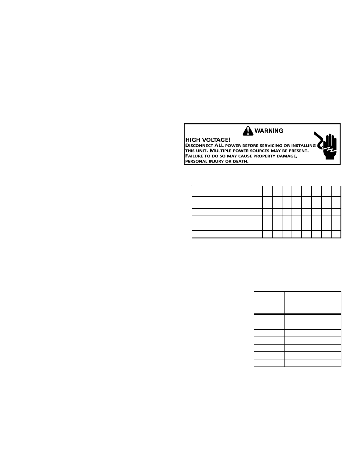
1. For branch circuit wiring (main power supply to unit disconnect), the minimum wire size for the length of run can be
determined using the circuit ampacity found on the unit rating plate and the table below. From the unit disconnect to the
unit, the smallest wire size allowable may be used for the ampacity, as the disconnect must be in sight of the unit.
2. Wire size based on 60°C rated wire insulation and 30°C Ambient Temperature (86°F).
3. For more than three conductors in a raceway or cable, see the N.E.C. for derating the ampacity of each conductor.
11
Page 12

For unit protection, use a fuse or HACR circuit breaker that is in
excess of the circuit ampacity, but less than or equal to the
maximum overcurrent protection device. DO NOT EXCEED THE
MAXIMUM OVERCURRENT DEVICE SIZE SHOWN ON UNIT DA T A PLA TE.
All line voltage connections must be made through weatherproof fittings. All exterior power supply and ground wiring must
be in approved weatherproof conduit. Low voltage wiring from
the unit control panel to the thermostat requires coded cable. See below for ground level and rooftop wiring.
Note :J u nction b o x loc a ti o n
shown is optional and is
for illustration purposes only .
JUNCTION BOX
Typical Electrical Wiring Unit Voltage
CIRCULATING AIR AND FILTERS
A
IRFLOW CONVERSION
Units can easily be converted from horizontal to down-discharge airflow delivery.
In down-discharge or high static installations, the installer should measure the
total external static and review the blower performance charts before performing the installation. In some installations it will be necessary to change the blower
speed to provide proper air flow.
HORIZONTAL AIR FLOW
Single phase models are shipped without horizontal duct covers. If needed, these
kits may be ordered through Goodman’s Service Parts department.
Down Discharge Applications
Cut insulation around bottom openings and remove panels from the bottom of
the unit, saving the screws holding the panels in place.
NOTE: Single phase models require installation of horizontal duct kit
#20464501PDGK (medium chassis) and #20464502PDGK (large chassis).
Duct Cover Installation
DUCTWORK
Duct systems and register sizes must be properly designed for the C.F.M. and external static pressure rating of the unit. Ductwork
should be designed in accordance with the recommended methods of Air Conditioning Contractors of America Manual D (Residential) or Manual Q (Commercial). All ductwork exposed to the outdoors must include a weatherproof barrier and adequate insulation.
A duct system should be installed in accordance with Standards of the National Board of Fire Underwriters for the Installation of Air
Conditioning, Warm Air Heating and Ventilating Systems. Pamphlets No. 90A and 90B.
12
Page 13

The supply duct from the unit through a wall may be installed without clearance. However, minimum unit clearances as shown in the
appendix must be maintained. The supply duct should be provided with an access panel large enough to inspect the air chamber
downstream of the heat exchanger. A cover should be tightly attached to prevent air leaks.
For duct flange dimensions on the unit refer to the Unit Dimension illustration in the appendix.
For down-discharge applications, the ductwork should be attached to the roof curb prior to installing the unit. Ductwork dimensions are shown in the roof curb installation manual.
If desired, supply and return duct connections to the unit may be made with flexible connections to reduce possible unit operating
sound transmission.
FILTERS
Even though a return air filter is not supplied with this unit,
there must be a means of filtering all return air. All units may be
externally filtered.
Refer to the unit filter size chart in the appendix for filter size
information.
Filters installed external to the unit should be sized in accordance with their manufacturer recommendations. A throwaway filter
must be sized for a maximum face velocity of 300 feet per minute.
Filter Installation
IMPORTANT NOTE: When installing a filter, the air flow arrows on the filter must point toward the circulator blower.
VENTING
NOTE: Venting is self-contained. Do not modify or block.
HOOD
INSTALLATION - FLUE HOOD EXHAUST
1. Locate the flue hood assembly box from the blower compartment.
2. Slide screen over flanges on the lower flue hood.
3. Slide screen into hood.
4. Using the three screws provided, attach the hood (with the opening
facing down) over the flue exhaust opening in the utility panel.
LOWER
FLUE
HOOD
SCREEN
INSTALLATION - COMBUSTION AIR INTAKE HOOD
1. Locate the second hood.
2. Using the three screws provided, attach the hood (with
the opening facing down) to the heat exchanger access
door.
LIP
13
Page 14

CONDENSATE DRAIN
C
ONDENSATE DRAIN CONNECTION
A 3/4” NPT drain connection is supplied for condensate piping. An
external trap must be installed for proper condensate drainage.
NORMAL SEQUENCES OF OPERATION
HEAT PUMP OPERATION
DRAIN
CONNECTION
UNIT 2" MINIMUM
FLEXIBLE
TUBING-HOSE
OR PIPE
A POSITIVE LIQUID
SEAL IS R E QUIRED
3" MINIMUM
O
UTDOOR THERMOSTAT
For optimal performance, a dual fuel thermostat with an outdoor temperature sensor should be used. TSTATGTS3275 (Emerson Dual Fuel thermostat) with TSTATTSORS (outdoor temperature sensor) is
recommended.
This will allow the installer to control when the unit switches from heat pump to gas heat based on a set point entered into the
thermostat. It is recommended to set the thermostat between 35° - 45°F, depending on regional climate and energy rates.
Drain Connection
OPTIONAL OUTDOOR THERMOSTAT (OTDFPKG-01)
The outdoor thermostat is an optional accessory that can be set from 0 - 45°F and is set inside a “birdhouse” enclosure. This
enclosure will be mounted near the blower access panel. The dimples and knock-out are located on the corner posts, providing
ease of installation. Once the thermostat closes, a 24 volt signal is sent to the W1 terminal instead of the Y terminal and the heating
cycle will change from Heat Pump to Gas heating. It is recommended to set the thermostat between 35-45°F depending on regional
climate and energy rates.
HEATING CYCLE (HEAT PUMP)
The heat pump operates in the heating cycle by redirecting refrigerant flow through the refrigerant circuit external to the
compressor. This is accomplished through the reversing valve. Hot discharge vapor from the compressor is directed to the indoor
coil (evaporator on the cooling cycle) where the heat is removed, and the vapor condenses to liquid. It then goes through the
expansion device to the outdoor coil (condenser on the cooling cycle) where the liquid is evaporated, and the vapor goes to the
compressor.
When the solenoid valve coil is energizing for cooling, the piston in the reversing valve to the low pressure (high pressure) reverse
positions in the reversing valve. In addition to a reversing valve, a heat pump is equipped with an expansion device for the indoor
coil, and similar equipment for the outdoor coil is provided with a defrost control system.
HEATING CYCLE (NATURAL GAS/ LP)
1. The Dual Fuel unit will operate in gas heat mode when the thermostat calls for a W-1 or W-2 signal. If outdoor thermostat is
installed, the unit will operate in gas heat when ambient is below set point or the unit receives call for low or high stage gas
heat.
2. Induced draft blower energizes for 15-second pre-purge.
3. A 7-second trial for ignition begins by energizing the low and high stages of the gas valve along with this spark ignition.
NOTE: The igniter produces a very intense electrical spark that ignites the gas.
4. Main burners light and control detects presence of flame.
5. If the call is for low stage heat, the induced draft blower switches from high to low speed and the gas valve from high to low
stage within 5 seconds after the main burners light. If call is for high stage heat, induced draft blower remains at high speed
and high stage gas valve remains open.
NOTE: If a W2 is not used, the control will step to low stage after the main burners light and remain at low stage for 5 or
10 minutes, depending on jumper position. If the jumper is set to none, you will never get a call for high stage heat. If the
call for HEAT remains after the transition delay time expires, the control will transition from low stage to high stage.
6. The 30-second HEAT FAN ON delay time begins after the main burners light.
7. The unit delivers heat to the conditioned space until the thermostat is satisfied.
8. Gas valve(s) de-energizes. The induced draft blower continues operation for a 30-second post-purge.
NOTE: Induced draft blower remains at low speed (or switches from high to low if operating at high stage heat) for the 30-
second post purge.
9. Ignition control begins timing the HEAT FAN OFF delay. There is an adjustable HEAT FAN OFF delay of approximately 90/120/
150/180 seconds (factory set at 150). If the unit is operating at high stage when the call for heat is removed, the blower will
operate for 30 seconds at high heat speed then switch to low heat speed for the remainder of the selected HEAT FAN OFF
delay.
NOTE: After the HEAT FAN OFF delay time has elapsed, the blower will de-energize. This allows any additional heat in the heat
exchanger to be transferred to the conditioned space.
14
Page 15

DEFROST CYCLE
NOTE: The defrost board is equipped with a jumper for SmartShift™ defrost technology operation. This operation turns the
compressor off for 30 seconds at defrost initiation and termination. The unit is factory shipped for SmartShift™ defrost technology
operation. To operate unit at rated efficiencies, move the jumper on the defrost board from “DLY” to “NORM”.
During operation the power to the circuit board is controlled by a temperature sensor, which is clamped to a feeder tube enteri ng
the outdoor coil. Defrost timing periods of 30, 60 and 90 minutes may be selected by setting the circuit board jumper to 30, 60 and
90 respectively.
Accumulation of time for the timing period selected starts when the sensor closes (approximately 34°F), and when the wall
thermostat calls for heat. At the end of the timing period, the unit’s defrost cycle will be initiated provided the sensor rem ains
closed.
Upon a call for defrost, the blower will continue to run and the defrost board will send a W1 signal to the ignition control. At the
same time the compressor will stop for 30 seconds, if the SmartShift™ defrost technology delay feature is selected on the defrost
board. At this time, the reversing valve shifts from heat to cool position and condenser fans shut off. The inducer motor will
immediately energize for a 15 second prepurge.
A 7-second trial for ignition begins by energizing the low and high stages of the gas valve along with this spark ignition. Main burners
light and control detects presence of flame. The compressor (after its 30/OFF second delay) restarts in cooling mode to defrost the
condensor coil.
When the sensor opens (approximately 60°F), the defrost cycle is terminated and the timing period is reset. If the defrost cycle is
not terminated due to the sensor temperature, a twelve minute override interrupts the unit’s defrost period. At this time the W1
signal is removed from the ignition control board, the compressor will stop for a 30 second SmartShift™ defrost technology delay (if
selected) and the reversing valve slides back to its normal heat position.
COOLING
1. Thermostat calls for cooling.
2. When the thermostat call is for cooling, the compressor and outdoor fan are energized .
3. The indoor blower will energize approximately 6 seconds later.
4. The unit delivers cooling to the conditioned space until the thermostat is satisfied.
5. The compressor and outdoor fan will be de-energized when the thermostat opens.
6. The indoor blower continues to run at low cool speed for approximately 60 seconds after the thermostat is satisfied. This
allows additional cooling from the indoor coil to be transferred to the conditioned space. Then, the indoor blower is deenergized.
NOTE: A 180-second anti-short cycle is integral to the control and prevents recycling of the compressor.
Cooling Operation
NOTE: Mechanical cooling cannot be reliably provided at ambient temperatures below 50° F.
1. Turn on the electrical power supply to the unit.
2. Place the room thermostat selector switch in the COOL position (or A UTO if available, and if automatic changeover from
cooling to heating is desired).
3. Set the room thermostat to the desired temperature.
FAN ONLY
1. Thermostat calls for FAN ONLY by energizing “G”.
2. The indoor blower is immediately energized at the low heat speed.
3. The indoor blower is immediately de-energized once thermostat call for FAN is removed.
AIR FLOW MEASUREMENT AND ADJUSTMENT
Please review the Duct Work section before proceeding with the airflow measurements and adjustments in this section.
Unit blower curves (see Specification Sheets) are based on external static pressure (ESP per in/W.C.). The duct openings on th e
unit are considered internal static pressure. As long as ESP is maintained, the unit will deliver the proper air up to the maximum
static pressure listed for the CFM required by the application (i.e. home, building, etc.)
In general, 400 CFM per ton of cooling capacity is a rule of thumb. Some applications depending on the sensible and latent capacity
requirements may need only 350 CFM or up to 425 CFM per ton. Check condition space load requirements (from load calculations)
and equipment expanded ratings data to match CFM and capacity.
After unit is set and duct work completed, verify the ESP with a 1-inch inclined manometer with pilot tubes or a Magnahelic gauge
and confirm CFM to blower curves in the Specification Sheets.
NOTE: Never run CFM below 350 CFM per ton, evaporator freezing or poor unit performance is possible.
AIR FLOW ADJUSTMENTS FOR INDOOR BLOWER MOTOR
EEM Motor
Adjust the CFM by changing the 24V low voltage lead at the speed terminal block on the motor. (T1, T2, T3, T4, T5). See Blower
Performance Data in the appendix for airflow delivered at each speed tap.
NOTE: Factory set T1 (G, fan and low stage gas heat), T2 (high stage gas heat, T4 (nominal heat pump / cooling).
T3 is for optional low speed cooling and heat pump. T5 is for optional high speed cooling and heat pump.
15
Page 16

START-UP, ADJUSTMENTS, AND CHECKS
H
EATING START-UP ( NATURAL GAS / LP)
This unit is equipped with an electronic ignition device to automatically light the main burners. It also has a power vent blower to
exhaust combustion products.
On new installations, or if a major component has been replaced, the operation of the unit must be checked.
Check unit operation as outlined in the following instructions. If any sparking, odors, or unusual sounds are encountered, shut off
electrical power and check for wiring errors, or obstructions in or near the blower motors.
Heat Anticipator Setting
Set the heat anticipator on the room thermostat to 0.4 amps to obtain the proper
number of heating cycles per hour and to prevent the room temperature from
overshooting the room thermostat setting.
Rollout Protection Control
The rollout protection device opens, cutting power to the gas valve, if the flames
from the burners are not properly drawn into the heat exchanger. The rollout
protection device is located on the burner bracket. The reason for elevated temperatures at the control must be determined and repaired prior to resetting this
manual reset control.
Rollout Protection on Burner Bracket
Rollout Protection
Secondary Limit Control
The secondary limit control is located on the top of the blower scroll assembly. This
control opens when elevated temperatures are sensed. Elevated temperatures at the
control are normally caused by blower failure.
If the power to the unit is interrupted during the heating cycle, it may cause the
secondary limit to trip. Once the blower compartment temperature drops below the
limit reset temperature, the limit will automatically reset.
Pre-Operation Checks
1. Close the manual gas valve external to the unit.
2. Turn off the electrical power supply to the unit.
3. Set the room thermostat to its lowest possible setting.
4. Remove the heat exchanger door on the side of the unit by
removing screws.
Open to
Atmosphere
M
5. This unit is equipped with an ignition device which automatically
lights the main burner. DO NOT try to light burner by any other
method.
6. Move the gas control valve switch to the OFF position. Do not
force.
7. Wait five minutes to clear out any gas.
8. Smell for gas, including near the ground. This is important because
some types of gas are heavier than air. If you have waited five
minutes and you do smell gas, immediately follow the warnings
on page 4 of this manual. If having waited for five minutes and no
gas smell is noted, move the gas control valve switch to the ON
position.
9. Replace the heat exchanger door on the side of the unit.
10.Open the manual gas valve external to the unit.
n
o
m
a
M
Inlet
Pressure Boss
e
t
e
r
11. Turn on the electrical power supply to the unit.
12. Set the thermostat to desired setting.
White-Rodgers Model 36G54 connected to Manometer
16
e
m
o
n
a
t
e
e
s
o
H
Outlet
Pressure Boss
On/Off Switch
Secondary
Control Limit
Back of Unit
Secondary Limit Control
r
High Fire Regulator
High Fire
Coil Terminal (HI)
Terminal (C)
Adjust
A
Common
Regulator
Vent
Low Fire
Regulator Adjust
Coaxial Coil
Termin al (M)
Page 17

Gas Supply And Manifold Check
Gas supply pressure and manifold pressure with the burners operating must be as specified on the rating plate.
Gas Inlet Pressure Check
Gas inlet pressure must be checked and adjusted in accordance to the type of fuel being consumed.
With Power And Gas Off:
1. Connect a water manometer or adequate gauge to the inlet pressure tap of the gas valve.
Inlet gas pressure can also be measured by removing the cap from the drip leg and installing a predrilled cap with a hose
fitting.
With Power And Gas On:
2. Put unit into heating cycle and turn on all other gas consuming
appliances.
NOTE: Inlet Gas Pressure Must Not Exceed the Maximum Value Shown
Natural Min. 5.0" W.C., Max. 10.0" W.C.
Propane Mi n. 11.0" W.C., Max. 13.0" W.C.
INLET GAS PRESSURE
Inlet Gas Pressure
in the Inlet Gas Pressure chart.
If operating pressures differ from above, make necessary pressure regulator adjustments, check
piping size, etc., and/or consult with local utility.
Gas Line
Gas
Shutoff
Valve
Manifold Pressure Check
1 Turn OFF gas to furnace at the manual gas shutoff valve external to the furnace.
Gas Line
To Furnace
2. Turn off all electrical power to the system.
3. Back outlet pressure test screw (inlet/outlet pressure boss) out one turn (counterclockwise,
not more than one turn).
4. Attach a hose and manometer to the outlet pressure boss of the valve.
Drip Leg Cap
With Fitting
Open To
Atmosphere
5. Turn ON the gas supply.
6. Turn on power and energize main (M) solenoid. Do not energize the HI solenoid.
Manometer Hose
7. Measure gas manifold pressure with burners firing. Adjust manifold pressure using the Manifold
Gas Pressure table.
8. Remove regulator cover screw from the low (LO) outlet pressure regulator adjust tower and
turn screw clockwise to increase pressure, or counterclockwise to decrease pressure.
9. Energize main (M) solenoid as well as the HI terminal.
10.Remove regulator cover screw from the HI outlet pressure regulator adjust tower and turn
Measuring Inlet Gas Pressure
Alternate Method
Manometer
screw clockwise to increase pressure, or counterclockwise to decrease pressure.
11.Turn off all electrical power and gas supply to the system.
12.Remove manometer hose from outlet pressure boss.
13.Turn outlet pressure test screw in to seal pressure port (clockwise,
7 in-lb minimum).
14.Turn on electrical power and gas supply to the system.
15.Turn on system power and energize valve.
16. Using a leak detection solution or soap suds, check for leaks at
pressure boss screw. Bubbles forming indicate a leak. SHUT OFF
GAS AND FIX ALL LEAKS IMMEDIATELY.
Natural Low Sta ge 1.6 - 2.2" w.c. 2.0 " w.c.
Propane Low Stage 5.7 - 6.3" w.c. 6.0" w.c.
Manifold Gas Pressure
Gas
Range Nominal
High Sta ge 3.2 - 3.8" w.c. 3. 5" w.c.
Hi gh Sta ge 9.7 - 1 0.3" w.c. 10 .0" w.c.
Manifold Gas Pressure
NOTE: For gas to gas conversion, consult your dealer for appropriate
conversion.
Gas Input (Natural Gas Only) Check
To measure the gas input use a gas meter and proceed as follows:
1. Turn off gas supply to all other appliances except the unit.
2. With the unit operating, time the smallest dial on the meter for one complete revolution. If this is a 2 cubic foot dial, divide
the seconds by 2; if it is a 1 cubic foot dial, use the seconds as is. This gives the seconds per cubic foot of gas being delivered
to the unit.
3. INPUT=GAS HTG VALUE x 3600 / SEC. PER CUBIC FOOT
Example: Natural gas with a heating value of 1000 BTU per cubic foot and 34 seconds per cubic foot as determined by Step 2, then:
Input = 1000 x 3600 / 34 = 106,000 BTU per Hour. NOTE: BTU content of the gas should be obtained from the gas supplier . This
measured input must not be greater than shown on the unit rating plate.
4. Relight all other appliances turned off in step 1. Be sure all pilot burners are operating.
Main Burner Flame Check
Flames should be stable, soft and blue (dust may cause orange tips but they must not be yellow) and extending directly
outward from the burner without curling, floating or lifting off.
17
Page 18

Temperature Rise Check
Check the temperature rise through the unit by placing thermometers in supply and return air registers as close to the unit
as possible. Thermometers must not be able to sample temperature directly from the unit heat exchangers, or false readings
could be obtained.
1. All registers must be open; all duct dampers must be in their final (fully or partially open) position and the unit operated for
15 minutes before taking readings.
2. The temperature rise must be within the range specified on the rating plate.
NOTE: Air temperature rise is the temperature difference between supply and return air.
With a properly designed system, the proper amount of temperature rise will normally be obtained when the unit is operated at
rated input with the recommended blower speed.
If the correct amount of temperature rise is not obtained, it may be necessary to change the blower speed. A higher blower speed
will lower the temperature rise. A slower blower speed will increase the temperature rise.
NOTE: Blower speed MUST be set to give the correct air temperature rise through the unit as marked on the rating plate.
External Static Pressure Check
The total external static pressure must be checked on this unit to determine if the airflow is proper.
Blower Speed Adjustments
Refer to the wiring diagram and airflow data in the appendix to
verify speed tap settings.
Depending upon the model, blower speeds are changed at the
indoor blower. The ignition control board has four blower speeds:
LOW HEAT, HI HEAT, LOW COOL and HIGH COOL.
O AVOID PERSONAL INJURY OR DEATH DUE TO ELECTRIC SHOCK, REMOVE
T
ELECTRICAL POWER FROM THE UNIT BEFORE CHANGING SPEED TAPS ON THE
BLOWER MOTOR.
WARNING
NOTE: FAN ONLY energizes at LOW HEAT speed.
The *PD14 models are equipped with EEM motors. EEM motors are
constant torque motors with very low power consumption. This
motor is energized by 24VAC. Adjust the CFM for the unit by
changing the 24VAC leads to the speed terminal block on the
motor.
NOTE: Heating airflow must be adjusted to provide the temperature
rise shown on rating plate. A higher speed tap may not provide
more airflow. Blower speeds are programmed to deliver adequate
airflow at rated external static pressure (ESP). Refer to airflow
table provided in the Appendix for details.
Limit Check
GAS HE ATING COOLING
Lead
Col or
White T1
Brown T2
Speed
Tap
Definition
Low
Speed Heat
High
Speed Heat
Lead
Color
Yellow T4
Speed
Tap
Definition
Cool/HP
T3
Optional Low
Speed
Cool/HP
Speed
T5 High Static
Check limit control operation after 15 minutes of operation by
blocking the return air grille(s).
1. After several minutes the main burners must go OFF . Blower will continue
to run.
2. Remove air restrictions and main burners will relight after a cool down
period of a few minutes.
Adjust the thermostat setting below room temperature.
1. Main burners must go OFF.
2. Circulating Air Blower will continue to run for 90, 120, 150 or 180 seconds,
depending on the setting.
LO COOL
HI COOL
LO HEAT
HI HEAT
U6
U7
U4
U3
U5
P1
K2
K1
NOTE: If necessary, adjust fan OFF delay settings to obtain satisfactory comfort level.
Unit Shutdown
1. Set the thermostat to lowest setting.
2. Turn off the electrical power supply to the unit.
3. Remove the heat exchanger door on the side of the unit by removing
screws.
4. Move the gas control valve switch to the OFF position. Do
not force.
5. Close manual gas shutoff valve external to the unit.
6. Replace the heat exchanger door on the unit.
7. If cooling and/or air circulation will be desired, turn ON
the electrical power.
18
SW1
SPEEDUP
FAULT
RECALL
BLOWER
OFF DELAY
STAGE
DELAY
F1
ECON
R C W1 W2
Control Board (Top)
GY1Y2
Page 19

COOLING START-UP
NOTE: Check all manual reset limit controls in heating circuit if
cooling mode does not operate.
Compressor Protection Devices
The compressor includes components which are designed to
protect the compressor against abnormal operating conditions.
Refrigerant Charge Check (Units with Fixed Orifice Devices)
After completing airflow measurements and adjustments the unit’s refrigerant charge must be checked. The unit comes factory charged, but
this charge is based on 325 CFM per ton and minimum ESP per AHRI test
conditions (generally between .15 -.28 ESP). When air quantity or ESP is
different than above, the refrigerant charge must be adjusted to the
proper amount. All package units with fixed orifice devices are charged
using the super heat method at the compressor suction line.
After superheat is adjusted it is recommended to check unit sub-cooling
at the condenser coil liquid line out. For charge adjustments, see superheat and subcooling charts shown for each model.
A/GPD1424***M41
A/GPD1430***M41
A/GPD1436***M41
A/GPD1437***M41
A/GPD1442***M41
A/GPD1448***M41
Design superheat & subcooling
@ 95 °F outdoor ambient temperature
Models # Superhe at ± 3°F Subcooling ± 3°F
10 11
610
11 10
11 10
815
13 10
MAINTENANCE
Have the gas heating section of the unit checked at least once a
year before the heating season begins, to be sure that the combustion air inlet and flue outlet hoods are not blocked by debris,
which would prevent adequate combustion air and a properly
operating vent system.
FILTER REPLACEMENT OR CLEANING
A return air filter is not supplied with this unit; however, there
must be a means of filtering all of the return air. The filter(s) may
be located in the return air duct(s), or return air filter grille(s). Consult with your installing dealer for the actual location of the
return air filter(s) for your unit.
Dirty filters are the most common cause of inadequate heating or cooling performance. Filter inspection should be made at least
every two months; more often if necessary because of local conditions and usage.
Dirty throwaway filters should be discarded and replaced with a new, clean filter. Dirty permanent filters should be washed with
water, thoroughly dried and sprayed with a filter adhesive before being reinstalled. (Filter adhesives may be found at many hardware
stores.) Permanent filters should last several years. However, should one become torn or uncleanable, it should be replaced.
CABINET FINISH MAINTENANCE
Use a fine grade automotive wax on the cabinet finish to maintain the finish’s original high luster. This is especially important in
installations with extended periods of direct sunlight.
CLEAN OUTSIDE COIL (QUALIFIED SERVICER ONLY)
The coil with the outside air flowing over it should be inspected annually and cleaned as frequently as necessary to keep the finned
areas free of lint, hair and debris.
CONDENSER, EVAPORATOR, AND INDUCED DRAFT MOTORS
Bearings on the air circulating blower motor, condenser motor and the combustion fan
motor are permanently lubricated. No additional oiling is required.
Flame
Sensor
FLAME SENSOR (QUALIFIED SERVICER ONLY)
A drop in the flame current can be caused by a nearly invisible coating on the flame sensor.
This coating, created by the fuel or combustion air supply, can be removed by carefully
cleaning the flame sensor with steel wool.
NOTE: After cleaning, the microamp signal should be stable and in the range of 4 - 6 microamps
DC.
FLUE PASSAGES (QUALIFIED SERVICER ONLY)
At the start of each heating season, inspect and, if necessary, clean the unit flue passage.
1. Shut off electric power and gas supply to the unit.
2. Remove burner assembly by disconnecting the gas line and removing the manifold bracket
from the partition panel.
19
Flame Sensor
Page 20

3. Remove the flue from the induced draft blower and the collector box cover from the partition panel.
4. The primary heat exchanger tubes can be cleaned using a round wire brush attached to a length of high grade stainless steel
cable, such as drain cleanout cable. Attach a variable speed reversible drill to the other end of the spring cable. Slowly rotate
the cable with the drill and insert it into one of the primary heat exchanger tubes. While reversing the drill, work the cable
in and out several times to obtain sufficient cleaning. Use a large cable for the large tube, and then repeat the operation with
a small cable for the smaller tube. Repeat for each tube.
5. When all heat exchanger tubes have been cleaned, replace the parts in the reverse order in which they were removed.
6. To reduce the chances of repeated fouling of the heat exchanger, perform the steps listed in “Start-up, Adjustments, and
Checks”.
MAIN BURNER FLAME (QUALIFIED SERVICER ONLY)
Flames should be stable, soft and blue (dust may cause orange
tips but must not be yellow). The flames must extend directly
outward from the burner without curling, floating or lifting off.
At least once a year, prior to or during the heating season, make
a visual check of the burner flames.
NOTE: This will involve removing and reinstalling the heat exchanger door on the unit, which is held by two screws. If you
are uncertain about your ability to do this, contact a qualified
servicer.
If a strong wind is blowing, it may alter the airflow pattern within
the unit enough that an inspection of the burner flames is not
possible.
Check the burner flames for:
1. Good adjustment
2. Stable, soft and blue
3. Not curling, floating, or lifting off.
Burner Flame
1. Shut off electric power and gas supply to the unit.
2. Remove the screws securing the manifold to the burner
retention bracket. Remove the manifold and rotate each
burner counterclockwise to remove.
Burner
3. Remove the burners.
4. Use a bottle brush to clean burner insert and inside of the burners.
5. Replace burners and manifold, inspect the burner assembly for proper seating
of burners in retention slots.
Burner
Bracket
6. Reconnect electrical power and gas supply.
Manifold
Manifold Assembly
For further information on the yearly inspection, consult the User Manual. It is recommended that a qualified servicer inspect
and service the unit at least once each year.
Turn the unit on at the thermostat. Wait a few minutes, since any dislodged dust will alter the normal flame appearance. Flames
should be predominantly blue and directed into the tubes. They should not be yellow. They should extend directly outward from
the burner ports without curling downward, floating or lifting off the ports.
20
Page 21

APPENDIX
21
Page 22

TROUBLESHOOTING
(S)
DIAGNOSTIC
LED - RED
ON
OFF
1 FLASH
2 FLASHES
3 FLASHES
4 FLASHES
5 FLASHES
6 FLASHES
ST A T US
NORMAL OPERATION
NO POWER OR
INTERNAL CONTROL
FAUL T
IGNI TION FAILURE
PRESSURE SWITCH OPEN
WITHOUT INDUCER ON
OPEN LIMIT SWITCH
FA LSE FLAM E DETECTED
COMPR. SHORT CYCLE DE L AY
CHECK
CHECK
-
-
CHECK INPUT POWER
CHECK FUSE
GAS FLOW
GAS PRES SUR E
GAS VALVE
FLAME SENSOR
CHECK PRESSURE SW ITCH
CHECK TUBING
CHE CK VE NT MO TOR
CHE CK PRESS URE SWITCHPRESSURE SWITCH CLOSED
CHECK WIRING FOR SHORTS
CHECK MAIN LIMIT SWITCH
CHECK AUXILIARY LIMIT SW.
CHECK ROLLOUT LIMIT SW.
CHECK GAS VALVE
CHECK FOR SHORTS IN
FLAME SENSOR WIRIN G
3 MIN COMP. SHORT
CYCLE DELAY
DIAGNOSTIC
LED - AMBER
OFF
ON
1 FLASH
2 FLASHE S
STATUS
NO FLAME PRESENT
LOW FLAME SIGN AL
FALSE FLAME DETECTED
CHECK
-
-NORMAL FLAME PRESENT
GAS FLOW
GAS PR ES SU RE
GAS VALVE
FLAME SENSOR
CHECK GAS VALVE
CHECK FOR SHORTS IN
FLAME SENSOR WIR ING
NOTE:
Fault Recall
The ignition control stores the last 5 faults in memory with the most recent fault indicated
first. To retrieve the faults, depress the fault recall button for 2 seconds while in the standby mode. To clear the fault memory , depress fault button for 5 seconds but not more than 10
seconds.
22
Page 23

IGNITION CONTROL DIAGNOSTIC INDICATOR CHART
Red Light Signal Refer to Abnormal Heating or Cooling Operation Sections of this Manual
Off Internal Control Failure
1 Flash External Lockout
2 Flashes Pressure Switch Stuck Open
3 Flashes Pressure Switch Stuck Closed
4 Flashes Thermal Protection Device Open
5 Flashes Flame Detected with Gas Valve Closed
6 Flashes Short Cycle Compressor Delay (Cooling Only)
7 Flashes Limit Opened Five (5) Times Within The Same Call For Heat
8 Flashes Indoor/Outdoor Thermostat Open (Cooling Only; Devices Not present On All Models)
9 Flashes High Pressure/Loss of Charge Switch Open (Cooling Only; Devices Not Present On All Models)
Amber Light Signal Refer to Abnormal Heating or Cooling Operation Sections of this Manual
Off No Flame Present
On Normal Flame
1 Flash Low Flame Current
2 Flashes Flame Detected with Gas Valve De-energized.
HEATING TIMING CHART
HIGH
Circulator
Blower
Gas Valve
LOW
OFF
HIGH
LOW
OFF
Igniter
Induced
Draft
Blower
Thermostat
Seconds
ON
OFF
HIGH
LOW
OFF
HIGH
LOW
OFF
0 15 22 27 52 0 30
COOLING/HEAT PUMP TIMING CHART
Circulator
Blower
Compressor
Outdoor Fan
HIGH
LOW
OFF
HIGH
LOW
OFF
HIGH
LOW
OFF
90, 120, 150, 180
23
Page 24

UNIT DIMENSIONS
SUCTION/LIQUID PRE SSU RE PORT S
BEHIND COMPRESSOR ACCESS PANEL
COMBUST I O N AIR INT A KE
HEAT EXCHANGE A CCESS PANEL
CONDE N SA TE DRAIN CO NN EC T ION
F
O
R
Y
E
T
T
I
N
V
E
A
C
R
G
20
24
47
GAS SUPPLY ENTRANCE
3/4" NPT FEMALE
FLUE EXHAUST
HOOD
C
4 3/4
16 1/8
19 1/8
7 5/16
7 7/8
POWER WIRE ENTRANCE
CONTROL WIRE ENTRANCE
18 7/16
FLUE EXHAUST
7 15/16
51
16
1 3/8
5 1/2
16
B
B
DIMENSION
(INCHES)
SUPPLY
MEDIUM
3
EVAPORATOR/CONTROL PANEL ACCESS PANEL
RETURN
LARGE
A3240
B1618
C9 1/214
A
2 3/4
5 1/4
COMBUSTION
AIR INTAKE
SUPPLY
EXHAUST FLUE HO OD
BLOWER ACCESS PANEL
11
5 3/4
22
11
RETURN
22
24
Page 25

WIRING DIAGRAM
[A/G]PD14[24-48]***M41**
R
D
B
S RC
COMP
K
Y
L
YL
LPS
YL
P
K
Y
/
L
P
K
Y
/
L
R
D
PK
ALS
DFT
BL/PK
BL/PK
HPS
OR
P1 - PIN # 1
OR
PS
RS
P1 - PIN # 6
YL
P1 - PIN # 8
YL
OR
OR
P1 - PIN # 3
R
D
G
R
WH
VM
B
L
B
K
C
EM
T1
T3T2
BK
BL
P
U
NGL
T5T4
YL
.
ISCONNECT POWER BEFORE SE RVICING
D ALL .
RD
SEE NOTE 3
ULTIPLE POW ER S O URCES MAY BE PRESENT A ILURE TO DO
SO MAY CAUSE PROPERTY DAMAGE, PERSONAL INJURY OR DEA TH
HIGH VOLTAGE!
M. F
SEE NOTE 4
BR
IGN
FS
RD
BK
R
D
BK
B
R
P
U
B
K
B
R
CM
H
C
R
D
F
RCCF
Y
L
B
K
P
U
B
C
Y
Y
RD
R-PS1
PS2
PK
CCR
HVDR
DF2
BK
LS
BK
OR
RD
L
DC
LVDR
RD
B
DF1
PU
PU
P
U
P
U
B
L
B
L
6
3
R
D
BK
2
P
U
B
L
B
L
P1 - PIN # 5
SEE NOTE 8
R
D
PU
O
H
W
4
1
PU
1
C
BL
P
U
T2
T1
B
L
R
R
H
W
W
O
R
SEE NOTE 2
BK
3
2
240
208
TR
R
D
24V
RD
B
L
OR
RVC
BK
B
L
B
L
L
C
C
C-RV
CNT
O
O-RV
W
R
R
R-DFT
DFT
BL
B
L
O
R
PU
O
R
P
U
H
W
R
D
B
L
O
R
RD
D
R
PU
RD
P
U
B
L
O
R
P1 - PIN # 2
P
BK
RD
PU
B
L
BK
R
D
BL
P
U
BK
PU
O
R
P
U
PU
P
U
U
P
U
L2
OR
R
D
BL
Y
L
B
R
H
W
FS
5
LO COOL
4
24VAC COM
3
HI COOL
2
HI HEAT
1
LO HEAT
T1
OR
RD
ECON
O
R
B
L
LO
INDUCER
RD
F
BK
BK
BK
RD
HI
OR
BL
1
2
3
OR
RD
BK
BK
BK
L1
ODF
HILO
BK
C
I
I
YL
6
5
4
BR
BL
P1
7
8
5
YL
9
6
H
W
Y
L
PU
W2
C
R
G
W1
G
H
W
BR
BL
RD
SEE NOTE 7
CHS
P
U
P
U
L2
C
L1
D
H
BK
BK
P
U
BK
BK
GND
H
W
W
BK
H
W
W
P
U
BK
PARK
P
U
3
2
1
YL
Y1
R
H
W
P2
YL
P
U
Y2
YL
BK
H
H
PU
P
U
SEE NOTE 5
H
W
CH
GR
BK
SEE NOTE 4
2
0
8
2
4
0
/
1
/
6
0
Y
321
P
L
O
T
P
U
Y
L
H1
GV
C
M
BR
BL
PU
P1 - PIN # 7
P1 - PIN # 5
P1 - PIN # 9
SEE NOTE 4
W1
ROC
THERMOSTAT CLASS 2 WIRES
GY
W2
CONTROL
BOX
0140G04500-C
Wiring is subject to change. Always refer to the wiring diagram on the unit for the most up-to-date wiring.
25
Page 26

[A/G]PD14[24-48]***M41** WIRING DIAGRAM
L1
CH
T1
C
IIC
LO
L1
ODF
HI
LO
INDUCER
HI
L1
L1
P1
F
2
.
IS CONNECT POWER BE F O R E SERVICI NG
D ALL .
UL TIPLE P OW ER SOURCES MAY BE PRESENT AILURE TO DO
SO MA Y CAUSE PROPERTY DAMAGE, PERSONA L INJURY OR DEATH
HIGH VOLTAGE!
M. F
DIAGNOSTIC
5 FL ASHES
6 FLA SHES
1
3
R
6
W1
8
W2
2 FLA SHES
3 FLA SHES
4 FLA SHES
9
TO
MICRO
7
5
Y2
C
P2
1
Y1
4
5
3
6
2
G
TO
MICRO
LO HEAT
1
HI HEAT
2
COOL
5
P9
RCW1 GY1Y2
RCW2W1
W2
G
THERMOSTAT
LED - RED
ON
OFF
1FLASH
COMPR. SHORT CYCLE DELAY
SUPPLY VOLTAGE
SEE NOTE 7
SEE NOTE 8
C
COMP
DC
DF2
DF1
HVDR
VM
EM
3
TR
PS
DC
R
CNT
C
++
STATUS
NORMAL OPERATION
NO POWER OR
INTERNA L CONTROL
FAULT
IGNITION FAILURE
PRESSURE S W ITCH OPEN
WITHOU T IND UCER ON
OPEN LIMIT S WITCH
FALS E FLAME DETEC T ED
208-230/1/60
CHS
R
S
CM
2
LSALS
M
HI
C
DR
6
RVC
C-RV
R-DFT
DFT
T1
T2
EM
T3
T5
T4
2
1
OTP
Y1
C
T2
C
RCCF
H
F
SEE NOTE 3
SEE NOTE 2
1
RS
GV
4
2
1
3
HPS
Y
O
O-RV
DFT
C
SEE NOTE 5
PS2
R-PS1
LPS
SEE NOTE 6
3
O
CHECK INPUT POWER
CHECK FUSE(S)
REPLACE CONTROL
GAS PRESSURE
GAS VALVE
FLAME SENS OR
CHECK PRES SURE SW ITCH
CH ECK TUB ING
CHECK VENT MOTOR
CHECK PRE SSURE S W ITCHPRESSURE S W ITCH CLOSED
CHECK WIRING FOR SHORTS
CHECK MAIN LIMIT SWITCH
CHE CK AUXILIARY LIMIT SW.
CHECK ROLLOU T LIMIT SW.
CHEC K GAS VA LVE
CHECK FOR SHOR TS IN
FLAME SENSOR WIRING
3MINCOMP.SHORT
CYCLE DELAY
IIC
PARK
W
C
CHECK
CHECK
-
-
GA S FLOW
L2
COMPONENT LEGEND
ALS AUXILLARY LIMITSWITCH
C CONTACTOR
CH CRANKCASE HEATER
CHS CRANKCASE HEATER SWITCH
CM CONDENSER MOTOR
COMP COMPRESSOR
DC DEFROSTCONTROL BOARD
DFT DEFROST THERMOSTAT
DR DEFROST RELAY
L2
EM EVAPORATOR MOTOR
L2
L2
L2
L2
FFUSE
FS FLAME SENSOR
GND EQUIPMENTGROUND
GV GAS VALVE
HPS HIGHPRESSURESWITCH
IIC INTEGRATED IGNITIONCONTROL
IGN IGNITOR
LPS LOW PRESSURE SWITCH
LS LIMIT SWITCH
OTP OUTD OOR THERMOSTAT PLUG
P1 9 PIN CONNECTOR PLUG
P2 6 PIN CONNECTOR PLUG
PS PRESSURE SWITCH
RCCF RUN CAPACITOR COMPRESSOR / FAN
RS ROLLOUT SWI TC H
RVC REVERSINGVALVECOIL
TR TRANSFORMER
VM VENT MOTOR
ACTORY WIRING
F
LINE VOLTAGE
LOW VOLTAGE
OPTIONAL HIGH
VOLTAGE
F
IELD WIRING
HIGH VOLTAGE
LOW VOLTA GE
IRE CODE
W
BK BLACK
BL BLUE
BR BRO W N
GR GREEN
OR ORANGE
PK PINK
PU PURPLE
RD RED
WH WHITE
YL YELLOW
NOTES
1. REPLACEMENT WIREMUST BE THE SAME SIZE AND TYPEOF
INSULATIONAS ORIGINAL (AT LEAST 105°C). USE COPPER
CONDUCTOR ONLY.
2. FOR 208V TRANSFORMER OPERATIONMOVE BLACK WIRE FROM
TERMINAL 3 TO TERMINAL 2 ON TRANSFORMER.
3. F OR 208VVENT MOTOR OPERATION, REMOVE BLUE LEAD FROM
INDUCER LOW TERMINAL. MOVE BLACKLEAD FROM PARK TERMINAL
TO INDUCERLOW TERMINAL,AND PLACE BLUE LEAD ON PARK.
4. USE COPPER CONDUCTORS ONLY.
++ USE NEC CLASS 2 WIRE.
5. F OR OUTDOORTHERMOSTAT, R EMOVE PLUGFROM HARNESS AND
CONNECT PLUG FROM OUTDOOR THERMOSTAT TOHARNESS.
6. TO CHANG E AIRFLOW MOVE YELLOW WIRE (COOLING / HEAT PUMP),
WHITE W IRE (LOW STAGE GAS), ORBROWN WIRE (HIGH-STAGE GAS)
TO SPEED TAPT1, T2, T3, T 4, OR T5 AT EVAPORATOR MOTOR.
REFER TO UNIT AIRFLOW TABLES FOR TO DETERMINE THE
APPROPRIATE SPEED TAP F OR APPLICATION. UNITS SHIPPED W ITH
YELLOW, WH I TE, AND BROWN ON T4, T1, AND T2RESPECTIVELY.
7. CRANKCASE HEATER ANDCRA N KCASE HEATER SWITCHFACTORY
EQUIPPEDWHEN REQUIRED.
8. DOUBLE POLECONTACTOR SHOWN. SINGLE POLE CONTACTOR
COULD BE FACTORY EQUIPPED AS AN ALTERNA TE CONFIGURATION.
JUNCTION
TERMINAL
INTERNAL TO
INTEGRATED CONTROL
PLUG CONNECTION
IGNITER
SWITCH (PRESS.)
DIAGNOSTIC
LED - R ED
7 FLA SHES
9 FLA SHES
DIAGNOSTIC
LED - AMBER
OFF
ON
1FLASH
2 FLA SHES
FALS E FLAME DETECTED
STATUS
LIMIT OPEN 5 TIMES IN
SAME CALL FOR HEAT
IDT/ODT OP E N8 FLA SHES
PSW/LOC OPEN
STATUS
NO FLAME PRESENT
LOW FLAME SIGNAL
EQUIPMENT GROUND
FIELD GROUND
FIELD SPLICE
SWITCH (TEMP)
OVERCURRENT
PROT. DEVICE
CHECK
CHECK MAIN LIMIT SWITCH
CHECK AUXILIARY LIMIT SW.
CHECK JUMPER BETWEEN
1AND4ON6-CIRCUIT
CONNECTOR
CHEC K OPTIONAL
REFRIGERANT SWITCHES
CHECK REFRIGERANT
SW ITCHES FOR LOSS OF
CHARGE ORHIGHHEAD
PRESS UR E
CHECK
GAS FL OW
GAS P RE SSURE
GAS VALVE
FLAME SENSOR
CHECK GAS VAL VE
CH ECK FOR S HORTS I N
FLAME SENSOR WIRING
-
-NORMAL FLAME PRES ENT
0140G04501-A
Wiring is subject to change. Always refer to the wiring diagram on the unit for the most up-to-date wiring.
26
Page 27

MINIMUM CLEARANCES
Clearance in accordance with local installation codes, the
requirements of the gas supplier and the manufacturer ’s
installation instructions.
Dégaugement conforme aux codes d’installation locaux, aux
exigences du fournisseur de gaz et aux instructions
d’installation du fabricant
RECOMMENDED FILTER SIZES
UNIT 2 Ton 2 1/2 Ton 3 Ton 3 1/2 / 4 Ton
Min. Filter Size (1)20 x 20 x 1 (1)20 x 25 x 1 (1)25 x 25 x1 (2)20 x 20 x 1
NOTE: Roof overhang should be no more than 36".
27
Page 28

THIS PAGE LEFT INTENTIONALLY BLANK
28
Page 29

BLOWER PERFORMANCE DATA
*PD1424060M41A* - Rise Range: 35° - 65°
E.S.P
ST
1
CFM W ATTS RISE CFM W ATTS RISE CFM W ATTS CFM WATTS CFM WATTS
0.1 616 51 55 845 105 53 859 94 8 85 103 1048 140
0.2 581 60 58 809 116 56 810 102 836 111 999 148
0.3 535 69 63 774 124 58 761 109 788 118 950 155
0.4 476 79 X 736 134 61 713 117 740 126 901 163
0.5 422 87 X 695 140 65 664 125 692 134 852 171
0.6 365 95 X 646 14 8 X 615 133 643 142 803 179
0.7 334 101 X 580 161 X --- --- --- --- --- ---
0.8 300 103 X 532 167 X --- --- --- --- --- ---
*PD1424070M41B* - Rise Range: 35° - 65° F
E.S.P
ST
1
CFM W ATTS RISE CFM W ATTS RISE CFM W ATTS CFM WATTS CFM WATTS
0.1 708 57 50 1004 12 9 52 859 94 885 103 1048 140
0.2 659 65 57 955 137 54 810 102 836 111 999 148
0.3 610 72 63 906 145 56 761 109 788 118 950 155
0.4 561 80 X 857 153 59 713 117 740 126 901 163
0.5 512 88 X 808 160 63 664 125 692 134 852 171
0.6 --- --- --- 760 168 X 615 133 643 142 803 179
0.7 --- --- --- --- --- --- --- --- --- --- --- ---
0.8 --- --- --- --- --- --- --- --- --- --- --- ---
T1
Stage Heating Speed
T1
Stage Heating Speed
T2
2nd Stage Heating Speed
T2
2nd Stage Heating Speed
T3
Coo ling Speed
T3
Coo ling Speed
T4
Cooling Speed
T4
Cooling Speed
T5
Cooling Speed
T5
Cooling Speed
*PD143080M41A* - Rise Range: 35° - 65°
E.S.P
ST
T1
1
Stage Heating Speed
2nd Stage Heating Speed
T2
T3
Coo ling Speed
T4
Cooling Speed
T5
Cooling Speed
CFM W ATTS RISE CFM W ATTS RISE CFM W ATTS CFM WATTS CFM WATTS
0.1 997 147 45 1276 28 4 47 1059 137 1071 142 1333 234
0.2 965 155 47 1238 28 4 48 1008 144 1023 149 1285 242
0.3 922 165 49 1206 28 9 50 956 151 976 157 1237 250
0.4 886 173 51 1164 30 2 52 908 158 928 164 1189 257
0.5 835 182 54 1131 31 4 53 857 166 880 172 1141 265
0.6 781 188 58 1086 31 9 55 784 175 832 180 1094 273
0.7 731 200 62 1038 31 9 58 732 180 784 187 --- ---
0.8 677 202 X 984 322 61 673 188 736 195 --- ---
*PD1430090M41B* - Rise Range: 45° - 75° F
E.S.P
ST
T1
1
Stage Heating Speed
2nd Stage Heating Speed
T2
T3
Coo ling Speed
T4
Cooling Speed
T5
Cooling Speed
CFM W ATTS RISE CFM W ATTS RISE CFM W ATTS CFM WATTS CFM WATTS
0.1 1059 137 49 1260 213 55 1059 137 1071 142 133 3 234
0.2 1008 143.5 52 1212 221 57 1008 143.5 1023 149 1285 242
0.3 956 151 54 1165 22 9 59 956 151 976 157 1237 250
0.4 908 157.5 57 1117 236 62 908 157.5 928 164 1189 257
0.5 857 165.5 60 1069 244 64 857 165.5 880 172 1141 265
0.6 784 175 63 1021 25 2 68 784 175 832 180 1094 273
0.7 732 180 69 973 25 9 70 732 180 784 187 --- ---
0.8 673 187.5 72 - - - 673 187.5 736 195 --- ---
X = Outside of Temperature Rise Range - Not Recommended.
NOTE:
The shaded area indicates ranges in excess of maximum external static pressure allowable when heating. For satisfactory operation,
external static pressure should not exceed 0.5" w.c.
29
Page 30

BLOWER PERFORMANCE DATA
*PD1436080M41A* - Rise Range: 35° - 65°
T1
E.S.P
St age Heating Speed
1
2nd Stage Heating Speed
ST
CFM WATTS RISE CFM WATTS RISE CFM W ATTS CFM W ATTS CFM WATTS
0.1 997 147 45 1276 284 47 1317 230 1317 230 1453 269
0.2 965 155 47 1238 284 48 1269 237 1269 237 1405 277
0.3 922 165 49 1206 289 50 1221 245 1221 245 1357 284
0.4 886 173 51 1164 302 52 1174 253 1174 253 1309 292
0.5 835 182 54 1131 314 53 1126 260 1126 260 1261 300
0.6 781 188 58 1086 319 55 1078 268 1078 268 1213 307
0.7 731 200 62 1038 319 58 1030 276 1030 276 --- ---
0.8 677 202 X 984 322 61 982 283 982 283 --- ---
*PD1436090M41B* - Rise Range: 45° - 75° F
T1
E.S.P
ST
St age Heating Speed
1
2nd Stage Heating Speed
CFM WATTS RISE CFM WATTS RISE CFM W ATTS CFM W ATTS CFM WATTS
0.1 1053 143 49 1257 236 55 1136 181 1136 181 1408 304
0.2 1007 151 52 1211 243 57 1090 188 1090 188 1362 311
0.3 961 158 54 1165 250 59 1044 195 1044 195 1315 319
0.4 915 165 57 1119 258 62 997 203 997 203 1269 326
0.5 869 173 60 1073 265 64 951 210 951 210 1223 334
0.6 823 180 63 1027 273 68 905 218 905 218 1177 341
0.7 777 188 69 980 280 70 859 225 859 225 --- ---
0.8 731 195 72 --- --- --- 813 233 813 233 --- ---
T2
T2
T3
Cooling Speed
T3
Cooling Speed
T4
Cooling Speed
T4
Cooling Speed
Cooling Speed
Cooling Speed
T5
T5
*PD1437090M41A* - Rise Range: 45° - 75° F
E.S.P
T1
1ST Stage Heating Speed
2nd Stage Heating Speed
T2
T3
Cooling Speed
T4
Cooling Speed
Cooling Speed
CFM WATTS RISE CFM WATTS RISE CFM W ATTS CFM W ATTS CFM WATTS
0.1 1059 137 49 1260 213 55 1317 230 1317 230 1453 269
0.2 1008 144 52 1212 221 57 1269 237 1269 237 1405 277
0.3 956 151 54 1165 229 59 1221 245 1221 245 1357 284
0.4 908 158 57 1117 236 62 1174 253 1174 253 1309 292
0.5 857 166 60 1069 244 64 1126 260 1126 260 1261 300
0.6 784 175 63 1021 252 68 1078 268 1078 268 1213 307
0.7 732 180 69 973 259 70 1030 276 1030 276 --- ---
0.8 673 188 72 - - - 982 283 982 283 --- ---
*PD1442100M41A* - Rise Range: 35° - 65°
E.S.P
T1
ST
1
St age Heating Speed
2nd Stage Heating Speed
T2
T3
Cooling Speed
T4
Cooling Speed
Cooling Speed
CFM WATTS RISE CFM WATTS RISE CFM W ATTS CFM W ATTS CFM WATTS
0.1 1098 167 51 1423 324 53 1354 260 1501 320 1609 365
0.2 1038 178 54 1375 335 55 1296 267 1446 328 1556 373
0.3 991 184 57 1322 347 57 1237 275 1391 336 1504 381
0.4 932 192 60 1275 347 59 1178 283 1336 344 1451 388
0.5 871 204 65 1224 357 61 1120 291 1281 352 1399 396
0.6 811 213 X 1172 364 64 1061 299 1226 359 1347 404
0.7 753 210 X 1130 379 X 1002 306 1171 367 1294 412
0.8 704 221 X 1075 384 X 9 44 314 1116 375 1242 420
T5
T5
X = Outside of Temperature Rise Range - Not Recommended.
NOTE:
The shaded area indicates ranges in excess of maximum external static pressure allowable when heating. For satisfactory operation,
external static pressure should not exceed 0.5" w.c.
30
Page 31

BLOWER PERFORMANCE DATA
*PD1442115M 41B* - Rise Range: 45° - 75° F
T1
E.S.P
ST
1
Stage Heati ng Speed
2nd Stage Heating Speed
CFMWATTSRISE CFMWATTSRISE CFMWATTSCFMWATTSCFMWATTS
0.1 1090 150 52 1286 231 57 1354 260 1501 320 1609 365
0.2 1025 158 57 1225 239 61 1296 267 1446 328 1556 373
0.3 960 166 62 1165 247 64 1237 275 1391 336 1504 381
0.4 895 174 X 1105 255 X 1178 283 1336 344 1451 388
0.5 830 181 X 1045 262 X 1120 291 1281 352 1399 396
0.6 765 189 --- 984 270 X 1061 299 1226 359 1347 404
0.7 699 197 --- 924 278 - -- 1002 306 1171 367 1294 412
0.8 634 205 --- --- --- --- 944 314 1116 375 1242 420
*PD1448100M41A* - Rise Range: 35° - 65°
T1
E.S.P
ST
Stage Heati ng Speed
1
2nd Stage Heating Speed
CFMWATTSRISE CFMWATTSRISE CFMWATTSCFMWATTSCFMWATTS
0.1 1098 167 51 1423 324 53 1164 180 1397 315 1758 427
0.2 1038 178 54 1375 335 55 1100 188 1354 320 1709 435
0.3 991 184 57 1322 347 57 1037 196 1306 329 1660 443
0.4 932 192 60 1275 347 59 974 204
0.5 871 204 65 1224 357 61 910 212 1211 343 1563 458
0.6 811 213 X 1172 364 64 847 220 1168 356 1514 466
0.7 753 210 X 1130 379 X 784 227 1111 373 1466 474
0.8 704 221 X 1075 384 X 720 235 1066 373 1417 482
T2
T2
T3
Cooling Speed
T3
Cooling Speed
T4
Cooling Speed
T4
Cooling Speed
1261 338
T5
Cooling Speed
T5
Cooling Speed
1612 450
*PD1448115M 41B* - Rise Range: 45° - 75° F
E.S.P
T1
ST
1
Stage Heati ng Speed
2nd Stage Heating Speed
T2
T3
Cooling Speed
T4
Cooling Speed
Cooling Speed
CFMWATTSRISE CFMWATTSRISE CFMWATTSCFMWATTSCFMWATTS
0.1 1164 180 56 1435 293 61 1164 180 1675 392 1758 427
0.2 1100 188 59 1378 301 63 1100 188 1624 400 1709 435
0.3 1037 196 62 1322 309 65 1037 196 1573 408 1660 443
0.4 974 204 65 1265 316 68 974 204 1522 416 1612 450
0.5 910 212 70 1208 324 70 910 212 1472 424 1563 458
0.6 847 220 75 1152 332 73 847 220 1421 431 1514 466
0.7 784 227 X 1095 340 X 784 227 1370 439 1466 474
0.8 720 235 X 1038 348 X 720 235 1319 447 1417 482
T5
X = Outside of Temperature Rise Range - Not Recommended.
NOTE:
The shaded area indicates ranges in excess of maximum external static pressure allowable when heating. For satisfactory operation,
external static pressure should not exceed 0.5" w.c.
31
Page 32

Air Conditioning & Heating
Start-up Checklist
*Store in job file
Date: ___________________________________
Model Number: ___________________________________
Serial Number: ___________________________________
Technician: ___________________________________
Pre Start-Up
(Check each item as completed)
Verify all packaging material has been removed.
Remove all shipping brackets per installation instructions.
Verify the job site voltage agrees with the unit serial plate.
Verify condensate connection is installed per installation instructions.
Verify proper clearance around the unit for safety, service, maintenance and proper unit operation.
Verify proper weatherproofing of all ductwork, roof curbs and electrical connections.
Location: __________________________________________
__________________________________________
__________________________________________
Unit #: __________________________________________
Check that the flue screen is in place.
Check gas piping for leaks.
Verify gas pressure to the unit is within the range specified on the serial plate.
Check to ensure that all fans, pulleys and wheels are secure.
Check for proper belt tension and alignment per installation instructions.
Check refrigerant piping for rubbing and leaks. Repair if necessary.
Check unit wiring to ensure it is not in contact with refrigerant piping or sharp metal edges.
Check all electrical connections and terminals. Tighten as needed.
Verify that the crankcase heaters have been energized for 24 hours.
Verify the scroll compressor(s) are rotating in the right direction.
Verify all accessories are installed and operating correctly.
Check filters and replace if necessary.
Verify the installation of the thermostat.
is a r egistere d trademark of Ma ytag Corpora tion or its related companies and is used under license to Goodman Comp any , L.P., Houston, TX, USA. All rights reserved.
32
9/2014
Page 33

Air Conditioning & Heating
ELECTRICAL
Start-up Checklist
Start-Up
(Insert the values as each item is completed.)
Supply Voltage
Circ uit 1 Compressor Amps
Circ uit 2 Compressor Amps
Blower Amps
Condenser Fan Amps
BLOWER EXTERNAL STATIC PRESSURE
Return Air Static Pressure
Supply Air Stat ic Pressure
To ta l External St a tic Pr e s s ure
Blo wer Wheel RPM
TEMPERATURES
Outdoor Air T emperat ur e
Return Air Temperature
Co o lin g S u p p ly Air T em p e r atur e
He ating Supply A ir Tem pera ture
L1 - L2 L2 - L3 L3 - L1
L1 L2 L3
L1 L2 L3
L1 L2 L3
Fan 1Fan 2Fan 3
IN. W.C.
IN. W.C.
IN. W.C.
RPM
DB WB
DB WB
DB WB
DB
PRESSURES
Gas Inlet Pressure
Gas Manifold Pressur e
Superheat (Orifice System)
Superheat (Orifice System)
Discharge Circuit 1
Subcooling (TXV Syst em)
Discharge Circuit 2
Subcooling (TXV Syst em)
(HEAT PUMP ONLY)
Discharge Circuit 1
Discharge Circuit 2
Suction Cir cuit 1
Suction Cir cuit 2
Suction Cir cuit 1
Suction Cir cuit 2
IN. W.C.
IN. W.C. (Low Fire) IN. W.C. (High Fire)
PSIG °F
°F
PSIG °F
°F
PSIG °F
°F
PSIG °F
°F
PSIG °F
PSIG °F
PSIG °F
PSIG °F
33
Page 34

THIS PAGE LEFT INTENTIONALLY BLANK
34
Page 35

THIS PAGE LEFT INTENTIONALLY BLANK
35
Page 36

CUSTOMER FEEDBACK
We are very interested in all product comments.
Please fill out the feedback form on one of the following links:
Goodman® Brand Products: (http://www.goodmanmfg.com/about/contact-us).
Amana® Brand Products: (http://www.amana-hac.com/about-us/contact-us).
You can also scan the QR code on the right for the product brand
you purchased to be directed to the feedback page.
PRODUCT RE GISTRA TION
Thank you for your recent purchase. Though not required to get the protection of
the standard warranty, registering your product is a relatively short process, and
entitles you to additional warranty protection, except that failure by California
and Quebec residents to register their product does not diminish their warranty
rights.
For Product Registration, please register as follows:
Goodman® Brand products:
(https://www.goodmanmfg.com/product-registration).
Amana® Brand products: (http://www.amana-hac.com/product-r egistration)
You can also scan the QR code on the right for the product brand
you purchased to be directed to the Product Registration page.
GOODMAN® BRAND
GOODMAN® BRAND
AMANA® BRAND
AMANA® BRAND
NOTE: SPECIFICA TIONS AND PERFORMANCE DATA LISTED HEREIN ARE SUBJECT T O CHANGE WITHOUT NOTICE
Quality Makes the Difference!
All of our systems are designed and manufactured with the same high quality standards regardless of
size or efficiency. We have designed these units to significantly reduce the most frequent causes of
product failure. They are simple to service and forgiving to operate. We use quality materials and
components. Finally, every unit is run tested before it leaves the factory.
That’s why we know. . .There’s No Better Quality.
Visit our website at www.goodmanmfg.com or www.amana-hac.com for information on:
• Products • Parts
• Warranties • Contractor Programs and Training
• Customer Services • Financing Options
© 2011-2018 Goodman Manufacturing Company, L.P.
is a registered trademark of Maytag Corporation or its related companies and is used under license. All rights reserved.
36
 Loading...