

Page 1
Installation/Owner’s Manual
1802 1808 1810 Access Plus
1810
7
8
9
4
5
6
1
2
3
0
3
2
4
23
1
3
3
2
1
1
7
D
i
x
o
n
D
D
o
m
i
n
i
c
k
P
D
o
n
i
ck
P
Do
n
n
er
K
D
on
t
er
F
3
2
2
0
6
8
8
8
8
5
1
8
3
5
8
4
6
7
7
6
5
9
5
4
9
9
2
H
en
d
r
i
x
K
Hi
r
d
A
H
i
t
ch
J
H
i
t
ch
F
H
o
d
g
es
A
H
o
o
ver
H
J
en
se
n
D
Jo
h
n
so
n
M
Jo
h
n
so
n
T
Jo
n
es
A
Jo
n
es
G
1
2
0
7
3
2
18
6
2
3
2
3
3
3
8
3
5
3
0
2
0
6
4
0
0
5
4
9
0
3
4
1
8
7
9
5
5
7
0
3
2
4
1
9
L
ev
i
n
e
D
L
ew
i
s B
L
u
ci
d
i
B
M
an
c
i
n
i
G
M
ast
i
n
D
M
as
t
o
n
F
M
o
zi
n
a
J
M
u
ce
r
a
J
M
u
l
i
n
B
N
ab
o
r K
N
ab
u
r
J
N
eu
man
n
J
Ni
xo
n
R
P
a
t
t
er
so
n
F
P
e
r
ez
F
P
e
t
r
o
l
l
i
A
R
ay
J
0
2
6
9
9
6
3
3
8
4
7
6
1
0
1
0
6
9
2
4
7
1
2
2
0
4
0
6
4
0
4
4
7
0
0
6
7
4
5
5
4
6
5
0
1
3
3
0
2
1
1
5
4
3
9
8
7
3
5
2
R
es
s
eg
i
e
u
R
R
o
l
l
i
n
s
A
S
ch
u
st
er
S
S
ee
l
ey
J
S
el
l
ec
k
H
S
h
a
er
R
S
h
a
n
k
D
S
i
m
o
n
s
L
S
m
i
t
h
J
S
o
m
a
c
h
H
S
t
e
e
l
e
F
S
t
o
l
l
ac
h
H
S
yn
f
o
l
A
T
o
m
l
in
s
o
n
L
T
o
mp
s
o
n
A
T
o
mp
so
n
S
T
yl
er
Q
W
as
hi
n
g
t
o
n
G
W
a
s
h
i
n
g
t
o
n
K
W
e
n
t
L
W
hi
t
i
n
g
M
W
i
n
st
o
n
F
W
ya
t
t
J
0
8
1
1
4
8
8
8
7
0
6
3
8
8
3
5
5
1
7
3
1
4
3
5
0
5
5
0
8
2
65
0
7
9
1
0
2
1
07
6
1
0
0
3
3
4
2
1
3
2
2
9
0
0
7
1
3
4
6093
8
9
67
9
2
1
1
6
7
0
4
4
1
1802
7
8
9
4
5
6
1
2
3
0
1808
7
8
9
4
5
6
1
2
3
0
NA
ME
A
d
ams
J
B
e
r
n
a
r
d
E
B
r
o
wn
L
Da
v
i
s
T
Ho
dg
e
s
S
Miller
J
S
m
it
h
K
T
h
o
mas
W
Z
im
me
r
R
1
9
5
2
4
6
8
3
7
C
ODE
7
8
9
4
5
6
1
2
3
0
O
pera
ti
n
g
I
ns
t
r
u
c
t
ions
c
a
t
e
C
o
de
N
u
m
b
e
r
O
n
D
ir
e
c
t
o
ry
7
6
5
9
5
4
9
92
Jen
se
n
D
Jo
h
n
so
n
M
Jo
h
n
so
n
T
Jo
n
e
s
A
Jo
n
e
s
G
3
0
2
0
64
0
05
4
9
0
3
4
1
87
9
5
5
7
03
2
4
1
9
M
u
ce
r
a
J
Mul
i
n
B
N
ab
o
r
K
N
ab
u
r
J
N
e
u
m
a
n
n
J
Ni
x
o
n
R
P
at
t
er
so
n
F
P
e
r
ez
F
P
et
r
o
l
l
i
A
R
ay
J
2
4
7
1
2
2
0
4
0
6
4
0
4
4
7
0
0
6
7
4
5
5
4
6
50
1
3
3
0
21
1
5
4
3
9
8
7
3
5
2
S
i
m
o
n
s L
S
m
i
t
h
J
S
o
m
a
c
h
H
S
t
e
e
l
e
F
S
t
o
l
l
ac
h
H
S
yn
f
o
l
A
T
o
m
l
i
n
so
n
L
T
o
m
p
so
n
A
T
o
m
p
so
n
S
T
yl
er
Q
W
as
h
i
n
g
t
o
n
G
W
a
sh
i
n
g
t
o
n
K
W
en
t
L
W
h
i
t
i
n
g
M
W
i
n
st
o
n
F
W
y
at
t
J
7
3
1
4
3
5
0
5
5
0
8
2
6
5
0
7
9
1
0
2
1
0
7
6
1
0
0
3
3
4
2
1
3
2
2
9
0
0
7
1
3
4
6
0
9
3
8
9
6
7
9
2
1
1
6
7
0
4
4
1
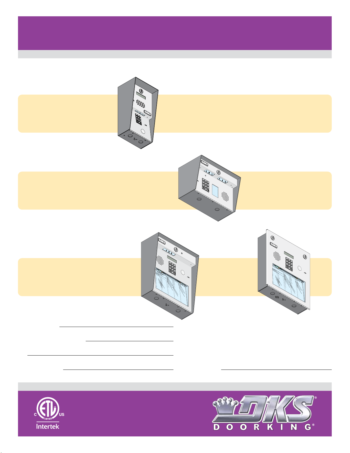
PC Programmable Telephone Entry/Access Control System
1802 1808 1810 Access Plus
1802 1808 1810 Access Plus
Use this manual for circuit board 1970-010 Revision U or higher.
Control a main door, gate and six additional RS-485 entry points.
Surface Mount
1
2
3
1802
1802
Access Plus
1808
1808
Access Plus
1802-092
INS
1
.
L
ocate
D
ir
2.
Press Code Number.
If Li
B
T
3.
E
4
5
6
7
8
9
OP
E
RA
0
T
T
RUC
ING
TIONS
Co
e
c
d
to
e
ry.
N
u
mb
ne
e
utt
r
i
s
o
on
B
n
usy
ry
to
Agai
,
H
P
a
ress
n
ng
te
n
.
r
U
A
on
p
n
.
y
Ton
e
.
Surface Mount
1
2
3
4
5
7
6
NA
ME
A
8
d
ams
B
e
J
r
n
9
a
r
B
d
r
E
o
wn
Da
0
L
v
i
s
Ho
T
dg
e
Miller
s
S
J
S
m
it
h
T
K
h
o
mas
Z
im
W
me
r
R
1808-085
1810-162-A-6-16
C
ODE
1
9
5
2
4
6
8
3
7
1810
1810
Access Plus
Date Installed:
Installer/Company Name:
Phone Number:
Leave Manual with Owner
Surface Mount
1
2
3
4
5
7
6
8
1
2
3
NA
M
E
1810-095
Copyright 2016 DoorKing, Inc. All rights reserved.
9
0
R
es
s
L
eg
ev
i
i
e
n
H
R
u
e
en
o
R
D
1
3
D
2
i
4
x
o
n
D
23
D
o
1
m
i
n
i
c
3
k
D
3
o
2
n
i
ck
P
1
Do
1
7
n
n
er
K
D
on
t
er
F
l
0
l
d
L
i
2
8
n
r
ew
0
1
s
i
3
x
0
A
2
i
2
K
Hi
s B
S
2
6
ch
r
7
d
1
u
L
3
A
4
st
u
2
0
6
8
P
8
8
8
5
1
8
3
5
8
4
6
7
7
6
5
9
5
4
9
9
2
8
ci
9
er
9
d
H
S
S
6
i
i
B
ee
t
ch
18
8
l
M
8
ey
6
7
J
an
3
J
3
c
H
S
i
8
i
n
el
t
ch
i
2
0
l
ec
G
M
3
6
F
2
3
ast
k
4
H
7
H
S
i
6
n
o
h
D
d
a
3
8
er
M
g
3
8
es
3
3
R
as
1
A
0
t
H
S
o
1
o
h
n
o
8
a
5
F
n
M
ver
3
5
k
5
1
o
0
D
zi
H
6
J
S
n
9
en
a
i
m
3
7
J
se
M
0
o
3
n
2
1
n
u
s
2
ce
D
4
L
Jo
S
r
7
m
a
h
0
4
J
i
n
M
t
6
3
h
so
4
5
u
J
1
l
n
i
2
n
Jo
S
M
2
B
o
h
0
m
0
n
N
0
5
a
so
5
ab
5
c
0
h
n
o
4
H
Jo
S
T
r K
0
t
e
n
4
0
e
es
N
9
8
l
e
0
ab
2
A
F
6
u
4
Jo
S
r
0
J
t
o
n
3
65
l
es
N
4
l
ac
1
eu
0
G
h
4
man
4
S
H
7
yn
8
7
n
f
Ni
7
9
o
9
J
1
l
xo
0
A
0
n
T
6
o
R
m
5
0
P
5
2
l
in
7
a
1
t
s
7
t
er
o
4
T
n
5
o
so
L
mp
0
07
n
P
3
2
e
F
6
s
r
o
5
ez
n
4
T
6
o
A
F
mp
4
1
P
1
0
9
e
0
so
t
5
r
o
n
0
T
l
1
yl
l
S
i
er
A
3
R
3
Q
ay
4
3
J
3
W
0
as
2
1
hi
3
n
2
g
1
W
t
1
o
a
n
2
s
G
2
h
9
i
n
5
g
4
W
t
3
o
e
n
0
n
K
0
t
7
L
9
8
W
7
hi
1
t
3
i
n
4
g
3
5
M
W
2
i
n
60
st
9
o
n
F
W
ya
3
8
t
t
9
J
67
9
2
1
1
6
7
0
4
4
1
Circuit Board
Serial Number
and Revision Letter:
Flush Mount
1
2
3
4
5
7
6
8
1
.
Lo
2
3
1810-096
9
O
c
a
t
e
C
o
de
pera
0
ti
n
N
g
u
m
I
b
ns
e
r
t
O
r
n
u
D
c
ir
t
ions
e
c
t
o
ry
Jen
3
se
M
0
2
n
u
7
ce
D
6
Jo
5
r
a
h
0
J
n
Mul
64
so
9
n
5
i
n
Jo
4
M
B
h
0
n
N
05
so
ab
9
n
92
o
Jo
T
r
K
n
4
e
N
9
s
0
ab
A
u
Jo
r
J
n
3
e
N
4
s
1
e
G
u
m
a
n
87
n
Ni
9
J
x
o
n
R
5
P
5
7
at
t
er
so
03
n
P
2
e
F
r
ez
F
4
P
1
9
et
r
o
l
l
i
A
R
ay
J
S
i
m
7
o
3
n
1
s L
2
4
S
7
m
4
i
t
3
h
5
J
1
2
S
2
o
m
0
5
a
5
c
0
h
4
S
H
0
t
e
0
e
8
l
e
2
F
6
4
S
0
t
o
6
l
l
5
ac
0
h
4
4
S
H
7
yn
7
f
9
o
1
l
0
A
0
T
6
o
m
0
2
l
i
n
1
so
7
4
T
n
5
o
L
m
0
7
p
6
so
5
n
4
T
6
o
A
m
1
0
p
0
so
50
n
T
S
1
yl
er
3
3
Q
4
3
3
W
0
as
2
1
h
3
i
n
21
g
W
t
1
o
a
n
2
sh
G
2
9
i
n
5
g
4
W
t
3
o
en
n
0
K
0
t
L
7
9
8
W
7
h
1
i
t
3
i
n
4
g
3
5
M
W
2
i
n
6
st
0
9
o
n
W
F
y
3
at
8
t
9
J
6
7
9
2
1
1
6
7
0
4
4
1
UL Listed
Copyright 2009 DoorKing, Inc. All rights reserved.
Page 2

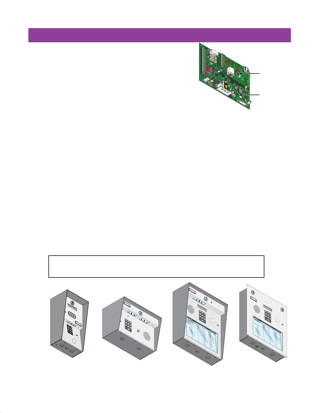
QUICK GUIDE: Terminals & LED Descriptions
J1
J1
Phone In
(Twisted Pair)
OR
Wireless
Adapter
Phone Out
(Twisted Pair)
Emergency
and/or Postal
Entry Switch
Back-Up
Battery Power
Relay 1
(Access Control Device)
Relay 2
(Access Control Device)
Input Power
(Transformer)
DO NOT
use 24V.
1. Phone In (Negative - Ring)
18-PIN Terminal
2. Phone In (Positive - Tip)
3. Ground (Required)
4. Phone Out (Positive - Tip)
5. Phone Out (Negative - Ring)
6. Not Used.
7. Switch Input Relay 1. A switch closure across terminals 7 & 9
will activate relay 1 for its programmed strike time.
8. Switch Input Relay 2. A switch closure across terminals 8 & 9
will activate relay 2 for its programmed strike time.
9. - 12 VDC Battery Negative. Also Common for terminals 7 & 8.
10. + 12 VDC Battery Positive.
11. Relay 1 Normally Open
12. Relay 1 Normally Closed
13. Relay 1 Common
14. Relay 2 Normally Open
15. Relay 2 Normally Closed
16. Relay 2 Common
17. 16.5 VAC Input Power
18. 16.5 VAC Input Power
WARNING
Maximum
input voltage to terminals
9 and 10 is 14.5 Volts DC.
BATT CHARGE LED: When
battery is connected to 9
and 10, Green LED will
light when charging and
turn OFF when charged.
Over Voltage Power Note: OV LED will light up if too much power is applied to circuit board.
1970-010
J1
1
2
3
4
5
6
7
8
9
10
11
12
13
14
15
16
17
18
OV
J4
1
2
3
4
5
6
7
8
BATT
CHARGE
1970-010
J1
1
2
3
4
5
6
7
8
9
10
11
12
13
14
15
16
17
18
RS-485 DATA A (+)
RS-485 DATA B (-)
RS-485 Common
Terminals 4-8 are
ONLY used with
1816 Access Plus
Telephone
Interface
application.
See section 1.9.
J4
1
2
3
4
5
6
LAN CONNECTION
CONNECTION
7
8
8-PIN
Terminal
SW2
TERMINATION
BAD DNS
LAN
ON
J1
RJ-45
RJ-45
Jack
Connector
(Cat5)
(Cat5)
RS-485 RX
RS-485 RX
LAN DOWN
LAN DOWN
DATA
DATA TRANSMIT
TRANSMIT
SW1
ON
MODEM / TCP ENB
MODEM / TCP ENB
PHONE LINE
1972-010
Interface Board
J3
KEYPAD
PHONE LINE
IN USE
IN USE
MIC VOL
MASTER
CODE
Microphone
Gain Adjust
Speaker
OV
1970-010
SPEAKER
VOL
J2
1112345678910
Volume
Adjust
RS-485 RX - Green LED indicates that the system is on-line and scanning the RS-485 devices.
BAD DNS - Yellow LED indicates an email server problem, rejecting the mail server.
LAN DOWN - Red LED indicates a problem with the LAN. IP or Gateway (router) down or wrong gateway IP address.
PHONE LINE IN USE - Yellow LED indicates that the phone line is being used (dial-out, call forwarding, etc.).
LAN CONNECTION - Green LED indicates that the wire connection from the unit to the computer or router is good.
DATA TRANSMIT - Yellow LED indicates that the TCP / IP connection is transmitting data or sending an email.
SW1 - Modem/TCP Enable - Turning SW1 Off disables the modem and TCP / IP, but will speed up programming from the keypad.
SW2 - Termination Switch - Only used when RS-485 access control devices are being used (See section 1.11.1).
2 Quick Guide - 1
1810-162-A-6-16
Page 3
Quick Reference Table
Page # Factory SettingsSection Command
Section 2.1 Programming Master Code
Program a Master Code
2.132
Press Master
Code Button
NO Master Code
Programmed
Section 2.3 Programming Network Setup for a Computer
Enable / Disable TCP / IP Support - System Reboot
Set the Unit’s IP Address (reboot required)
Sub-Net Mask (reboot required)
Set the Gateway (Router) IP Address (reboot required)
NOT Programmable from Software.
Program from System Keypad ONLY.
Set the Port Number (reboot required)
34
34
35
35
35
2.3.1
2.3.2
2.3.3
2.3.4
2.3.5
*
*
*
*
*
5 0
5 1
5 2
5 3
5 6
192.168.001.030
255.255.255.000
192.168.001.001
Section 2.4 System Parameters Programming
Single or Multiple Systems
Single or Double Ring
Number of Resident Rings Before Unit Hangs Up
Talk Time
Relay Strike Time
Tone Open Numbers
Answer Incoming Call on X Rings
Call Waiting ON / OFF
Turn Speaker On / Control Relay from Phone Call
Set Call Forward Microphone Gain & Speaker Volume
Hang-Up Tone
(1816 Interface ONLY)
(1816 Interface ONLY)
(1816 Interface ONLY)
37
37
37
38
38
38
39
39
39
40
40
2.4.2
2.4.4
2.4.5
2.4.6
2.4.7
2.4.8
2.4.9
2.4.11
2.4.12
2.4.13
2.4.14
*
*
*
*
*
*
*
*
*
*
*
6 1
6 3
6 4
0 8
0 3
0 5
1 8
2 0
1 6
1 1
1 7
1 (Single System)
1 (Double Ring)
05 (5 Rings)
060 (60 Sec.)
Relay 1: 9 8 7 6
Relay 2: 5 4 3 2
Relays 3-8 Not Set
06 (6 Rings)
7 (Mic) 1 (Speaker)
Section 2.5 Directory Codes
Directory Codes 1 – 23 Pre-Set (1816 Interface ONLY)
Directory Codes 24 – 50 “Dial Phone Number”
Delete a Phone Number from Directory Codes 24 – 50
Delete All Phone Numbers from Directory Codes 24 – 50
40
40
41
41
2.5.0
2.5.1
2.5.2
2.5.3
*
*
*
*
4 0
4 1
4 2
4 3
Section 2.6 Access Codes for Access Control Devices
“Simple” Access Code Programming (Relays 1&2: 24/7 Operation)
Number of RS-485 Devices
Additional Relay Off-Line Function
“Time Zone Restricted” Device Access Code Programming
Delete an Access Code (Simple or Time Zone Restricted)
Delete All Access Codes for the Same Type of Device (Simple or TZR)
Program Temporary Access Codes
Delete Temporary Access Code
Delete All 10 Temporary Access Codes
(Up to 10)
41
41
42
42
42
42
43
43
43
2.6.1
2.6.2
2.6.3
2.6.4
2.6.5
2.6.6
2.6.7
2.6.8
2.6.9
*
*
*
*
*
*
*
*
*
0 2
0 9
0 7
7 0
7 1
7 2
7 3
7 4
7 5
Section 2.7 Time Functions
Time and Date Calendar Chip Programming
Automatic Relay Activation Time Zone Programming (Up to 4 zones)
Access Code Time Zone Programming (Up to 4 zones)
44
44
45
2.7.1
2.7.5
2.7.6
*
*
*
3 3
3 5
3 6
Section 2.8 Miscellaneous
Restore Factory Settings
Erase Transaction Log
Note: Program section numbers have been intentionally skipped that DO NOT apply to these Access Plus systems in this manual. This allows ALL of the
Access Plus manuals to remain in sync with each other when referencing programming numbers.
45
45
2.8.1
2.8.2
*
*
9 0
9 1
0
01030
1 Sec
1 (ON)
N / A
0
Empty
Empty
N/ A
N / A
Empty
0
0
Empty
N / A
N / A
Empty
N / A
N / A
Empty
Empty
Empty
N / A
N / A
1810-162-A-6-16
Quick Guide - 2
3
Page 4
SPECIFICATIONS
7
8
9
4
5
6
1
2
3
0
P
us
h
B
utton
T
o Cal
l
7
8
9
4
5
6
1
2
3
0
rn
ard
E
lli
n
g
s
L
ro
ke
r
T
B
ro
s
e S
B
ro
w
n
J
B
ro
w
n
K
B
r
ya
n
t
W
Byr
o
n
R
B
ya
n
G
2
2
1
3
2
1
2
4
9
4
7
6
0
0
3
1
1
2
2
9
2
8
2
2
4
9
1
3
2
4
2
3
1
3
3
2
1
1
7
C
o
lyer
R
C
o
rd
u
l
a
D
C
o
u
r
t
E
C
r
ains
G
D
al
to
n
B
D
an
ie
ls
R
D
a
w
ls
J
D
eL
ah
ae
M
D
i
ll
P
D
illo
n
M
D
i
x
o
n
D
D
o
m
in
i
ck
P
D
o
n
ick
P
D
o
n
n
er
K
D
o
n
ter
F
5
0
3
5
0
1
4
0
4
4
6
1
2
4
9
7
7
2
6
3
3
4
8
1
1
0
4
3
2
2
0
6
8
8
8
8
5
1
8
3
5
8
4
6
7
7
6
5
9
5
4
9
9
2
Fara
g
o
F
Farro
w
M
Fern
an
d
e
z
S
G
ar
f
ie
l
d
S
G
ar
r
ea
u
J
G
en
t
r
y
M
G
o
n
z
alez
H
H
ab
er
f
el
d
A
H
a
m
m
er
V
H
en
d
rix
K
H
ir
d
A
H
it
c
h
J
H
it
ch
F
H
o
d
g
es A
H
o
o
ve
r
H
Je
n
s
en
D
Jo
h
n
s
o
n
M
J
o
h
n
so
n
T
Jo
n
es
A
Jo
n
es
G
3
5
2
W
h
i
t
in
g
M
W
in
sto
n
F
W
y
at
t
J
1
3
4
6
0
9
3
8
9
6
7
9
2
1
1
6
7
0
4
4
1
7
8
9
4
5
6
1
2
3
0
7
8
9
4
5
6
1
2
3
0
c
a
t
e
C
o
de
N
u
m
b
e
r
O
n
D
i
r
ec
t
o
r
y
e
s
s
C
od
e
N
u
m
b
er.
I
f
L
in
e
I
s
Bu
s
y,
P
r
e
s
s
A
n
y
B
u
t
t
o
n
H
a
n
g
U
p
.
Tr
y
Ag
a
i
n
.
n
t
e
r
O
n
“O
P
EN
” D
i
s
p
l
a
y
o
r
T
o
n
e
.
J
M
e
J
so
n
H
g
a
t
e
B
l
l
i
n
gs
L
r
o
ke
r
T
B
r
o
se
S
B
r
o
w
n
J
B
r
o
w
n
K
B
r
y
an
t
W
B
y
r
o
n
R
B
y
an
G
2
4
9
47
6
0
0
3
11
2
2
9
2
8
2
2
4
9
1
3
2
4
23
1
3
3
2
11
7
C
o
u
r
t
E
C
r
ai
n
s
G
D
a
l
t
o
n
B
D
a
n
i
el
s
R
D
a
w
l
s
J
D
e
L
ah
ae
M
D
i
l
l
P
D
i
l
l
o
n
M
D
i
xo
n
D
D
o
m
i
n
i
ck
P
D
on
i
ck
P
D
o
n
n
e
r
K
D
on
t
e
r
F
5
0
1
4
0
4
4
61
2
4
9
7
7
2
6
33
4
8
1
1
0
4
3
2
2
0
68
8
8
8
5
18
3
5
8
4
6
7
7
6
5
9
5
4
9
9
2
Far
r
o
w
M
F
er
n
an
d
e
z
S
G
a
r
f
i
el
d
S
G
ar
r
ea
u
J
G
e
n
t
r
y
M
G
o
nz
al
ez
H
H
ab
e
r
f
el
d
A
H
a
m
m
er
V
H
e
nd
r
i
x
K
Hi
r
d
A
Hi
t
ch
J
H
i
t
ch
F
H
o
d
g
es
A
H
o
o
v
er
H
J
en
sen
D
J
o
h
n
so
n
M
J
o
h
n
so
n
T
J
o
nes
A
J
o
n
es
G
82
8
3
4
2
7
3
3
4
4
1
6
1
2
9
1
4
54
2
1
2
0
7
3
2
1
8
6
2
3
2
3338
3
5
30
2
0
6
4
0
0
5
49
0
3
4
1
8795
57
0
3
2
4
19
Jo
r
g
en
sen
B
K
l
ei
n
D
K
no
b
l
i
c
h
B
L
am
b
B
L
an
d
D
L
a
n
der
s
S
L
a
n
g
s
t
r
o
m
B
L
e
vi
n
e
D
L
e
w
i
s
B
L
u
ci
d
i
B
M
a
n
ci
n
i
G
6
79
2
1
1
6
70
4
4
1
J1
1
2
3
4
5
6
7
8
9
10
11
12
13
14
1
For 1802/1808/1810 Access Plus with circuit board
1970-010 Rev U or higher ONLY.
5
16
17
18
OV
Both Boards Together - 1970-010
Features
• IP Addressable – program from your PC using the DoorKing programming software via a LAN or WAN connection, or via a
built-in modem.
• When internet connection is provided, system can send e-mail notification on 58 selectable events and 20 access codes.
• Two internal relays allow the system to control a main entry gate plus a pedestrian access gate.
• Control up to six (6) additional entry points with card readers, keypads or wireless RF via RS-485 connection.
• 100 card / transmitter / keypad codes when programming from the software application.
• Holiday schedule.
• 500 event transaction buffer.
• Unique distinctive ring (when interfaced with the 1816 Access Plus telephone interface).
• Unit connects directly to the tenant’s existing telephone line. No additional monthly expense for a second telephone line (when
interfaced with the 1816 Access Plus telephone interface).
• Built in call waiting assures that incoming calls or guest calls are not missed (when interfaced with the 1816 Access Plus
telephone interface).
• Up to 27 preprogrammed dial-out telephone numbers + 23 pre-set phone interface lines (when using the 1816 Access
Plus telephone interface).
• Built-in clock / calendar.
• Four hold-open time zones.
• Entry code time zones.
• 10 temporary access codes.
• Unit can be programmed to work with PBX and KSU phone systems.
• Optional secondary keypad can be added for remote entry code activation of door or gate. Order part number 1812-082.
J4
1
2
3
4
5
ON
6
SW
2
7
RS-485
8
RX
BAD
DNS
J1
LA
N
DOW
RJ-45
N
SW
ON
Jack
1
(Cat5)
MODE
M
19
72-010
J3
KEYPAD
1970-010
J2
1
2
3
45
6
7
8910
MASTER
CODE
MIC VO
L
SPEAKE
R
VO
L
11
Interface Board
Control Board
Included with the system is an extra random keyed cabinet lock. If desired, for added security against
unauthorized entry into the system, the standard lock may be replaced with the random lock.
Note: DoorKing cannot replace this specific lock or keys if lost.
1
.
L
o
c
2
a
.
t
e
P
C
r
o
e
de
s
s
t
N
o
C
u
od
H
m
3
a
e
.
n
b
N
g
e
E
r
-
u
n
U
O
m
t
p
e
n
b
r
.
er.
D
N
Tr
O
A
i
n
y
M
r
ec
I
“O
E
f
Ag
L
t
o
A
P
in
a
d
r
EN
i
am
y
e
n
.
s
I
” D
s
J
A
Bu
k
i
i
n
s
s
s
p
M
y,
l
a
A
y
P
n
n
r
o
ese
e
r
s
T
J
s
A
o
n
A
d
n
er
n
e
so
.
n
A
p
H
p
l
e
g
a
t
e
B
B
i
l
l
i
C
n
gs
o
u
r
L
t
B
E
r
o
2
ke
C
4
r
9
r
ai
T
n
B
s
r
G
o
47
se
D
a
6
l
S
t
o
B
n
r
B
o
0
w
D
0
a
n
3
n
J
i
el
B
s
r
o
11
R
w
D
a
n
2
w
K
l
s
B
r
J
y
2
an
D
9
e
2
t
L
W
ah
B
ae
y
r
8
o
D
2
M
n
i
2
l
l
R
P
B
y
an
4
D
9
G
i
1
l
l
o
n
M
3
D
2
i
4
xo
n
D
23
D
o
1
m
i
n
i
ck
3
D
3
P
on
2
i
ck
P
11
D
o
7
n
n
e
r
K
D
on
t
e
r
F
1810
Flush
1
4
7
y
B
u
t
t
o
n
Far
r
o
w
5
M
0
F
1
er
n
an
4
d
0
e
G
4
z
a
S
r
f
i
el
d
4
61
S
G
ar
r
ea
2
u
4
J
G
9
e
n
t
r
y
7
M
7
G
2
o
nz
al
6
ez
33
H
H
ab
e
r
f
4
el
8
d
H
1
a
A
m
m
er
1
0
H
4
V
e
nd
r
i
x
3
2
K
Hi
2
r
d
A
0
68
Hi
t
ch
J
8
8
H
8
i
t
ch
F
5
18
H
o
d
g
es
3
5
A
H
8
o
o
v
er
4
H
6
J
7
en
sen
7
D
6
J
5
o
h
n
so
9
n
5
J
4
M
o
h
n
so
9
n
9
J
2
T
o
nes
A
J
o
n
es
G
2
3
5
6
8
9
0
Jo
r
g
en
sen
82
K
8
l
ei
B
n
D
3
K
4
2
no
b
l
i
c
7
h
L
3
B
am
3
b
B
4
L
4
an
1
d
D
6
L
1
a
2
n
der
s
9
L
S
1
a
4
n
g
s
t
r
54
o
L
m
e
2
vi
B
n
e
D
1
L
2
e
0
w
i
s
B
7
L
3
u
2
ci
d
i
B
1
M
8
6
a
n
ci
n
i
2
G
3
2
33
3
8
3
5
30
2
0
6
4
0
0
5
49
0
3
4
1
87
9
5
57
0
3
2
4
19
6
79
2
1
1
6
70
4
4
1
1810-162-A-6-16
1
2
3
4
5
7
6
1
1
2
3
4
1
2
3
4
5
6
7
8
9
OPERATING
INSTRUCTIONS
0
1
.
Lo
cate
Di
r
2.
Co
ector
Press Code
de
y
Num
.
If
L
i
n
ber on
e
B
u
i
Number
s
t
t
o
B
n t
Tr
u
s
y
o
y
3
,
A
Ha
.
P
.
gain
En
r
e
ng
te
ss
.
r
Up
A
o
n
n
.
y
T
one.
1802
5
7
8
0
1808
6
Push B
9
utt
T
o Call
on
2
3
N
A
M
E
B
ern
B
illin
B
B
B
1810
8
9
0
C
o
lyer
Fara
R
2
C
g
2
ard
o
o
1
rd
5
F
0
u
Farro
E
3
l
a
3
D
C
2
g
o
w
1
s
u
5
M
r
0
L
t
Fern
1
E
ro
2
ke
C
4
an
r
9
r
ains
4
d
T
0
e
G
z
4
ro
ar
G
S
4
f
s
D
ie
7
e S
al
6
l
d
4
to
6
S
G
n
1
ro
ar
B
0
r
w
D
0
ea
an
n
3
u
2
J
ie
4
J
G
B
9
ls
ro
en
1
R
w
D
t
1
r
a
n
y
2
w
7
K
M
7
ls
G
B
2
r
o
J
ya
n
2
D
z
9
n
alez
eL
2
t
6
W
ah
3
H
Byr
3
H
ae
ab
8
o
D
M
er
2
n
i
2
ll
f
4
R
el
P
8
d
H
B
1
ya
a
A
m
4
D
n
9
m
illo
1
G
1
er
0
n
H
4
V
M
en
3
D
d
2
rix
i
4
x
3
o
2
n
K
H
2
D
ir
d
2
D
3
A
o
1
m
0
6
in
H
8
it
i
ck
c
3
D
h
3
P
o
2
J
n
8
ick
8
H
8
it
P
ch
1
D
1
o
7
F
n
5
n
1
H
er
8
o
d
K
D
g
o
es A
n
3
ter
5
H
8
o
F
o
ve
r
4
H
6
Je
7
n
s
en
7
D
6
Jo
5
h
n
s
o
9
n
5
J
M
4
o
h
n
so
9
n
9
Jo
2
T
n
es
A
Jo
n
es
G
W
h
1
i
t
3
in
4
g
3
5
M
W
2
in
6
sto
0
9
n
W
F
y
3
at
8
t
9
J
6
7
9
2
1
1
6
7
0
4
4
1
Surface
DoorKing, Inc. reserves the right to make changes in the products described in this manual without notice and without obligation of DoorKing, Inc. to notify any persons of any such
revisions or changes. Additionally, DoorKing, Inc. makes no representations or warranties with respect to this manual. This manual is copyrighted, all rights reserved. No portion of this
manual may be copied, reproduced, translated, or reduced to any electronic medium without prior written consent from DoorKing, Inc.
4
Page 5

TABLE OF CONTENTS
Quick Guide: Terminals and LED Descriptions
Quick Reference Table
SPECIFICATIONS
Important Notices FCC - United States, DOC - Canada
General Information Installation Guidelines and Safety Information
SECTION 1 - INSTALLATION
1.1 Mount the Access Plus System
1.1.1 1802 Access Plus
1.1.2 1808 Access Plus
1.1.3 1810 Access Plus Surface Mount
1.1.4 1810 Access Plus Flush Mount
1.2 Postal Lock Installation
1.3 Telephone Line Wire
1.4 16.5 VAC Power Wiring ONLY!
1.5 Grounding and Surge Suppression
1.6 Wire ONE Unit to a Telco Line - Auto-Dialer
1.7 Wire ONE Unit to the Internet - Auto-Dialer
1.8 Wire Multiple Units - Auto-Dialer: Telco/Internet
1.9 1816 Access Plus Telephone Interface Wiring
1.10 Main Terminal Description
1.11 Access Plus System Interface Board
1.11.1 RS-485 8-Pin Connector Description
RS-485 Daisy Chain Wiring
RS-485 Configurations, Sample of Multiple Unit Configuration Connection (Auto-Dialer ONLY)
1.11.2 Network Connections
1.11.3 Phone Modem Connection
Quick Guide - 1
Quick Guide - 2
Previous Page
3
4
5
5
6
7-8
9-11
12-15
16
17
18
18
19
20
21
22-23
24
24
25
26
27
28-29
30
SECTION 2 - PROGRAMMING
2.1 Programming the Master Code
2.2 Programming Methods
2.3 Programming the Network Setup for a Computer
2.3.1 Enable / Disable TCP / IP Support - System Reboot
2.3.2 Set the Access Plus System IP Address (reboot required)
2.3.3 Sub-Net Mask (reboot required)
2.3.4 Set the Gateway (Router) IP Address (reboot required)
2.3.5 Set the Port Number (reboot required)
2.4 System Parameters Programming
Programming from the System Keypad
Programming from a Touch-Tone Telephone
Quick Reference Table
2.4.2 Single or Multiple Systems
2.4.4 Single or Double Ring
2.4.5 Number of Resident Phone Rings Before Unit Hangs Up
2.4.6 Talk Time
2.4.7 Relay Strike Time
2.4.8 Tone Open Numbers
2.4.9 Answer Incoming Call on X Rings
2.4.11 Call Waiting ON/OFF
2.4.12 Turn Speaker On / Control Relay from Phone Call
2.4.13 Set Call Forward Microphone Gain and Speaker Volume
2.4.14 Hang-Up Tone Number
31
31
32
33
33
33
34
34
34
35
35
35
36
37
37
37
38
38
38
39
39
39
40
40
1810-162-A-6-16
1
Page 6

TABLE OF CONTENTS
2.5 Directory Codes
2.5.0 Directory Codes 01 – 23 PRE-SET (1816 Access Plus Telephone Interface ONLY)
2.5.1 Directory Codes 24 – 50 Programming “Dial Phone Number”
2.5.2 Delete a Phone Number from Directory Codes 24 – 50
2.5.3 Delete ALL Phone Numbers from Directory Codes 24 – 50
2.6 Access Codes to Operate Access Control Devices
2.6.1 “Simple” Access Code Programming (Relays 1&2: 24/7 Operation)
2.6.2 Number of RS-485 Devices
2.6.3 Additional Off-Line Relay Function
2.6.4 “Time Zone Restricted” Access Code Programming
2.6.5 Delete an Access Code (Simple and Time Zone Restricted)
2.6.6 Delete All Access Codes for the Same Type of Device (Simple and Time Zone Restricted)
2.6.7 Temporary Device Access Code Programming
2.6.8 Delete a Temporary Device Access Code
2.6.9 Delete ALL Temporary Device Access Codes
2.7 Time Functions
2.7.1 Time and Date Calendar Chip Programming
2.7.5 Automatic Relay Activation Time Zone Programming (Up to 4)
2.7.6 Access Code Time Zone Programming (Up to 4)
2.8 Miscellaneous
2.8.1 Restore Factory Settings
2.8.2 Erase Transaction Log
SECTION 3 - ADJUSTMENTS
Speaker Volume
Microphone Gain
Interface Board LED Status
System Keypad
40
40
40
41
41
41
41
41
42
42
42
42
43
43
43
44
44
44
45
45
45
45
46
46
46
46
46
SECTION 4 - USER INSTRUCTIONS
4.1 Resident Operating Instructions
4.1.1 Granting or Denying a Guest Access
4.1.2 Call Waiting (1816 Access Plus Telephone Interface ONLY)
4.1.3 Dial-Out Phone Numbers
4.1.4 Access Codes
4.2 Remote Operation
4.2.1 Remote Programming (Touch-Tone Phone)
4.2.2 Remote Relay Activation (Touch-Tone Phone)
4.2.4 Remote Relay Activation Check (Touch-Tone Phone)
SECTION 5 - MAINTENANCE
5.1 Troubleshooting
5.2 Phone Line Polarity
5.3 Troubleshooting Table
5.4 Access Plus Wiring Schematic
5.5 Accessories
5.6 Programmed Information Log Sheets
Master Code, Relays, Access Codes and Time Zone Log Sheets; Directory Code / Dial-Out Phone Numbers Log Sheet;
Access Code Log Sheets (50 with phone numbers, 50 as access only), 1-10 Temporary Access Codes Log Sheet when using
software ONLY.
47
47
47
47
47
47
48
48
48
48
49
49
50
51
52
53
54-61
2
1810-162-A-6-16
Page 7

Important Notices
FCC – United States
This equipment has been tested and found to comply with the limits for a class A digital device, pursuant to Part 15 of the FCC
Rules and Regulations. These limits are designed to provide reasonable protection against harmful interference when the
equipment is operated in a commercial environment. This equipment generates, uses, and can radiate radio frequency energy
and, if not installed and used in accordance with the instruction manual, may cause harmful interference to radio communications. Operation of this equipment in a residential area is likely to cause harmful interference in which case the user will be
required to correct the interference at his own expense.
FCC Registration Number: DUF6VT-12874-OT-T
DOC - Canada
The Canadian Department of Communications label identifies certified equipment. This certification means that the equipment
meets certain telecommunications network protective, operational, and safety requirements. The Department does not guarantee the equipment will operate to the users satisfaction.
Before installing this equipment, users should ensure that it is permissible to be connected to the facilities of the local telecommunications company. The equipment must also be installed using an acceptable means of connection. The customer should be
aware that compliance with the above conditions may not prevent degradation of service in some situations.
Repairs to certified equipment should be made by an authorized Canadian maintenance facility designated by the supplier. Any
repairs or alterations made by the user to this equipment, or equipment malfunctions, may give the telecommunications
company cause to request the user to disconnect the equipment.
Users should ensure, for their own protection, that the electrical ground connections of the power utility, telephone lines, and
internal metallic water pipe system, if present, are connected together. This precaution may be particularly important in rural
areas.
CAUTION: Users should not attempt to make such connections themselves, but should contact the appropriate electric inspection authority, or electrician, as appropriate.
DOC Registration Number: 1736 4507 A
Notice:
The Load Number (LN) assigned to each terminal device denotes the percentage of the total load to be connected to a telephone
loop which is used by the device, to prevent overloading. The termination on a loop may consist of any combination of devices
subject only to the requirement that the sum of the load numbers of all the devices does not exceed 100.
Notice:
DoorKing does not provide a power transformer on units sold into Canada. Use only transformers that are CSA listed to power
the telephone entry system. The Access Plus system requires a 16.5-volt, 20 VA transformer.
1810-162-A-6-16
3
Page 8

General Information
• Prior to beginning the installation of the telephone entry system, we suggest that you become familiar with the
instructions, illustrations, and wiring guidelines in this manual. This will help insure that you installation is performed in
an efficient and professional manner.
• The proper installation of the telephone entry panel is an extremely important and integral part of the overall access
control system. Check all local building ordinances and building codes prior to installing this system. Be sure your
installation is in compliance with local codes.
• When used to control a door or pedestrian gate, try to locate the telephone entry system as near as possible to the entry
point. The unit should be mounted on a rigid wall to prevent excessive shock and vibration from closing doors or gates.
Continuous vibration and shock from slamming doors or spring-loaded pedestrian gates will damage the circuit board.
Under no circumstances should the unit be mounted directly to a moving door or gate.
• ADA mounting requirements for door control. The requirements below apply only when the telephone entry system is
being used to control entry through a public door only. If this system is used to control entry through a vehicular gate or
private entrance, the dimensions noted below do not apply.
1. If the clear floor space allows only forward approach to the system, the maximum high forward reach allowed is
48 inches above grade to the top of the keypad.
2. If the high forward reach to the system is over an obstruction of greater than 20 inches but less than 25 inches,
the maximum high forward reach allowed is 44 inches above grade to the top of the keypad.
3. If the clear floor space allows parallel approach by a person in a wheelchair, the maximum high side reach shall
be 54 inches above grade to the top of the keypad.
4. If the high side reach is over an obstruction of 24 inches or less, the maximum high side reach allowed is 46
inches above grade to the top of the keypad.
• When used to control a vehicular gate with an automatic gate operator, the telephone entry system must be
mounted a minimum of ten (10) feet away from the gate and gate operator, or in such a way that a person cannot
operate the entry system and/or touch the gate or gate operator at the same time.
• Be sure that the system is installed so that it is not directly in the traffic lane. Goose neck mounting post and kiosks
work well for these type systems. When planning where to locate the system, take into consideration traffic lane layouts,
turn around lanes for rejected access, conduit runs, power availability, etc.
• Environmental factors must also be taken into account. Surface mount units are designed for direct outdoor
installations, however it is preferable to protect them from direct exposure to driven rain or snow whenever possible.
Flush mount units must be protected from direct exposure to the elements.
• This telephone entry system contains a number of static sensitive components that can be damaged or destroyed by
static discharges during installation or use. Discharge any static prior to removing the circuit board from the lobby panel
by touching a proper ground device.
• Instruct the end user to read and follow these instructions. Instruct the end user to never let children play with or
operate any access control device. This Owner’s Manual is the property of the end user and must be left with them
when installation is complete.
4
1810-162-A-6-16
Page 9

SECTION 1 - INSTALLATION
Installation of the Access Plus Telephone Entry System involves the installation of the hardware and the wiring of these components. Be sure that all dirt, metal or wood debris is removed from inside after mounting it. Any debris inside could damage the
control board and cause the Access Plus system to malfunction during operation.
When the Access Plus system is used to control a vehicular gate with an automatic gate operator, it must be
mounted a minimum of ten (10) feet away from the gate and gate operator, or in such a way that a person
cannot operate the Access Plus system and/or touch the gate or gate operator at the same time.
WARNING
Included with the system is an extra random keyed cabinet lock. If desired, for added security against unauthorized entry into the system,
the standard lock may be replaced with the random lock. Note: DoorKing cannot replace this specific lock or keys if lost.
1.1 Mount the Access Plus System
Ground
Wire
18-PIN
1810
Surface
Mount
Enclosure
J1
1
2
3
4
5
6
7
8
9
10
11
12
13
14
15
16
17
18
OV
Terminal
J4
1
2
3
4
5
6
SW
ON
2
7
RS
-
8
4
85
RX
BAD
DNS
J1
LA
N
DO
W
N
RJ-
45
S
ON
W1
Jack
(Cat5)
M
ODE
M
M
A
S
TE
R
C
ODE
197
KEYP
AD
Door
2-01
0
Accessorie
Plug
M
IC
VO
L
1970-01
SP
0
E
J
AK
2
E
R
VOL
12
345
6
7
891
0
1
1
s
Keypad
Plug
Remove the Control
Board and Faceplate
The control board removal is the same
for all access plus systems.
CAUTION The control board contains
static sensitive components. Discharge
any static electricity from your hands
by touching a proper ground device
before removing the control board.
1810-162-A-6-16
Faceplate
Hing
e
Locknuts
Faceplate
Mfg.
in U.
S.
DO
A.
O
Ac
R
c
K
es
Thi
I
s
N
Control
s
pr
G
or more of
®
oduc
,
S
ince
I
N
S
t is manuf
C
olut
1948
P
.
atent
the foll
i
ons
N
ac
o.
ow
tured under on
ing
Da
te
U
.
S
.
P
atents
e
P
atent
.
No
.
Date
OTHER
PA
DOO
TE
NTS
RK
I
P
NG IN
ENDIN
C., IN
G
G
LEWOOD C
A
D
O
O
P
R
A
R
KI
T
NU
N
M
G
®
B
E
,
R
M
I
N
A
D
C
E
I
.
N
U
SA
R
E
V
SE
R
IA
L
N
O
.
1. Unlock and open the door.
2. Disconnect the keypad plug and
door accessories plug from the
control board.
3. Remove green ground wire.
4. Remove 18-PIN terminal from circuit
board. Not necessary for 1808.
ACCESS CON
S
YSTE
M
T
O
C
R
UT
O
U
O
N
DOOR
D
NI
L
FOR
O
O
T
R
S
K
In
M
U
IN
SE
g
S
l
G
e
/ W
w
TO
M
o
o
o
E
del
U
d
T
,
S
L
C
e
#
a
S
ri
1
a
9
T
8
l
C
0
D
00
#
3
ompl
0
2
S
1
94
er
F
.
i
C
e
i
e
s
.C
s
F
.
D
.C
Reg
U
.
C
F
.
6
i
R
s
P
V
tr
a
i
T
ng
rt
-1
ation
e
2
6
J
r
874
8
a
E
c
#
quiv
k
-
USOC R
OT
.
-T
0
.
0
A
J11C
or
W
5. Remove the 4 screws from board.
Carefully remove control board.
Keep the control board in a protected
area during the mounting installation.
6. Remove faceplate from the housing.
7. Mount enclosure, see following
pages for specific mounting of your
chosen access plus system.
5
Page 10
9
6
3
0
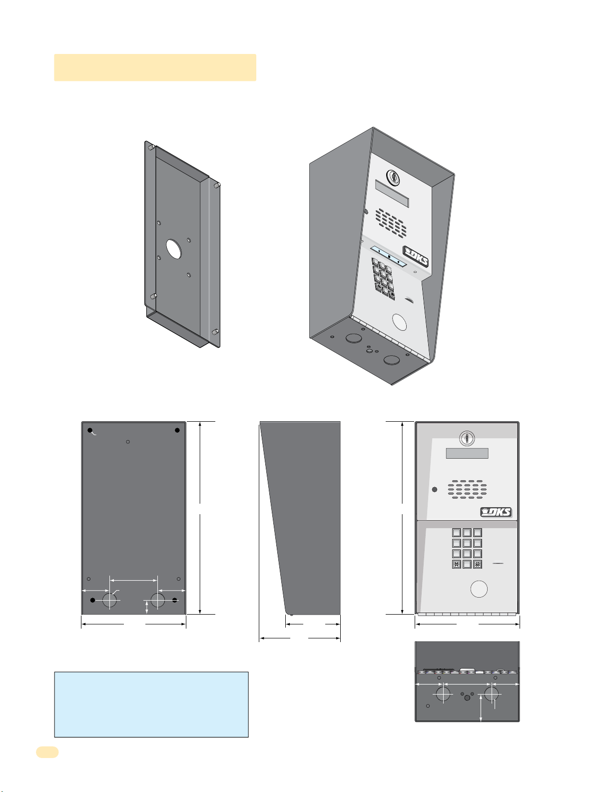
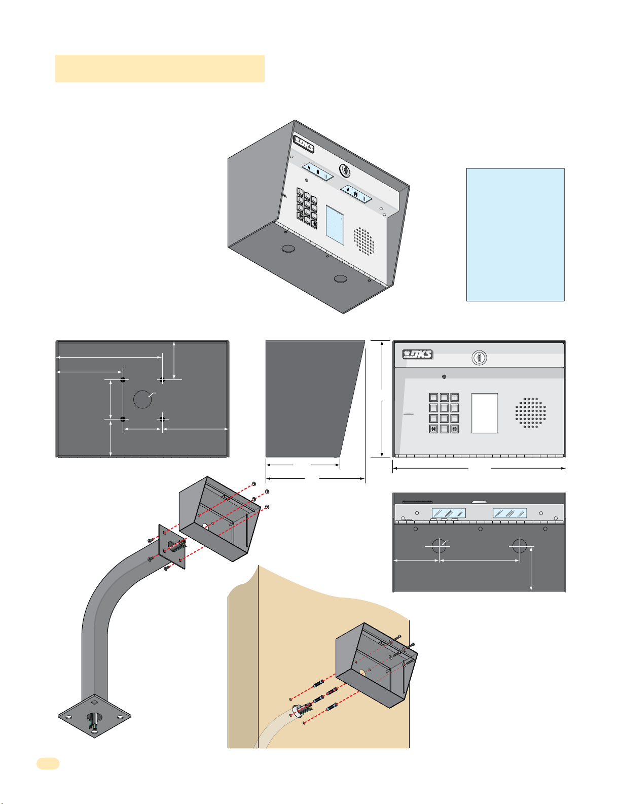
1.1.1 1802 Access Plus
7
8
9
4
5
6
1
2
3
0
Surface mount units can be mounted directly to a wall, pilaster, post mounted using a DoorKing Adapter Plate (P/N 1802-111)
with DoorKing mounting posts (P/N 1200-036, 1200-045, 1200-0046 and 1200-049). See next page. Be sure the unit is
mounted securely and is not subject to vibration from closing doors or gates.
Adapter
Plate
1
2
3
4
5
6
Sold
Separately
OPERATING
INSTRUCTIONS
1.
Locate Code
D
irecto
2.
Press Code Numb
If
Line is Busy
Button to
Tr
y Again
3.
Enter on To
7
8
9
0
ry.
N
u
m
ber
on
er.
, Pr
Hang
ess
.
U
Any
p
.
ne
.
.25” Dia. Mounting Hole
12” 12”
3”
1.75”
.875” Dia
.875”
1.75”
6.5”
WARNING! If this entry system is used to control a
vehicular gate with an automatic gate operator, the entry
system must be mounted a minimum of ten (10) feet away
from the gate and gate operator, or in such a way that a
person cannot operate the entry system and touch the gate
or gate operator at the same time.
Side ViewBack View Front View
11223
44556
77889
0
6.5”
3.375”
1.
2.
3.
OPERATING
INSTRUCTIONS
Locate Code Number on
Directory.
Press Code Number.
If Line is Busy, Press Any
Button to Hang Up.
Try Again.
Enter on Tone.
5”
1.625”
.875” Dia
Bottom View
1.75”1.75” 3”
6
1810-162-A-6-16
Page 11

1.1.1 1802 Access Plus Continued
The illustrations below show typical installations but specific installations can vary from this.
1. Mount the enclosure using the mounting holes provided in the corners (see sections 1.2 and 1.3 for your chosen model
dimensions). Be sure that mounting screws or nuts (Not supplied) do not protrude into the enclosure where they could cause a
short on the back of the circuit board. Make any necessary conduit connections through the back or bottom of the enclosure
using the existing conduit knock-outs. DO NOT make any new conduit holes in the enclosure.
2. Route all wiring through conduit or mounting post (not supplied) into enclosure.
3. Clean out the enclosure. Make sure that all dirt, metal and/or wood debris is removed.
4. Re-install components back into the enclosure (Reverse section 1.1). Use the wiring schematics in the back of this manual to
help re-install the components if necessary. DO NOT apply any power at this time.
Mount to a Mounting Post
There are different styles
of DoorKing mounting
posts. All mounting posts
need the adapter plate to
mount the 1802.
P/N 1802-111
Adapter
Plate
Sur
face
Mount
Enclosure
Use hardware supplied with
mounting post to secure
adapter plate to post.
Use hardware supplied with
adapter plate to secure
enclosure to adapter plate.
Note: A gooseneck
mounting post anchored
in concrete does not
make a good ground.
Knock-ou
ts
Mount ON a Surface
(See section 1.2).
Wall
Use appropriate
hardware to secure
enclosure to the wall
(not supplied).
Conduit run
to junction box
Conduit
sweep run
M
ou
nting
S.
.
U
in
I
Mfg.
K
R
C
OO
ess
D
c
c
A
u
d
o
r
p
s
ore
i
h
m
T
r
o
ten
Pa
Surface
Mount
Enclosure
S
crew
s
(Not
supplied)
.
A
.
e
C
s
on
N
.
s
I
r
on
t
i
n
e
,
de
®
t
ut
e
l
n
a
at
G
D
So
P
N
l
S.
o.
ro
ured u
t
.
t
N
1948
c
U
t
on
n
e
ng
nce
at
Si
anufa
P
owi
l
m
l
s
o
i
f
t
e
c
h
t
f
o
e
t
Da
G
N
I
A
o.
C
N
ND
t
E
P
OOD
NTS
EW
E
L
T
G
A
N
P
I
ER
NC.,
I
TH
O
G
N
I
K
R
O
O
D
Jack USOC RJ11C or W
Ringer Equiv. 0.0A
DUF6VT-12874-OT-T
F.C.C. Registration #
Complies F.C.C. Part 68
Serial #
Model # 1800 Series
Inglewood, Ca 90301
DOORKING
OUTDOOR USE / WET
SYSTEM UNITS
ACCESS CONTROL
CONFORMS TO UL STD 294
Knock-ou
ts
1810-162-A-6-16
Run all wires
inside post.
Examples of conduit runs that may be used, depending on how
you choose to run the wiring. Some installations will allow the
conduit to be run outside the wall and connect to the bottom of the
enclosure but this is generally NOT recommended.
7
Page 12
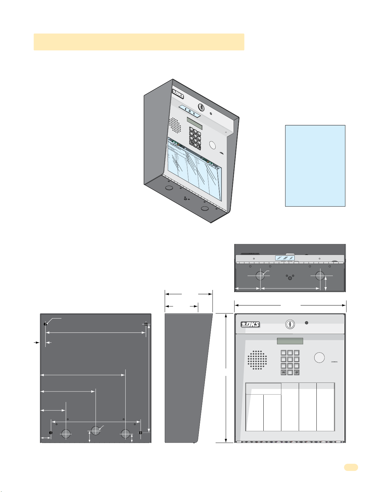
1.1.2 1808 Access Plus
7
8
9
4
5
6
1
2
3
0
NAME
Adams
J
Bernard E
Brown
L
Davis T
Hodges
S
Miller
J
Smith
K
Thomas
W
Zimmer R
1
9
5
2
4
6
8
3
7
CODE
9
6
3
0
1808 units can be mounted directly to a wall, pilaster, post mounted using a DoorKing mounting post (P/N 1200-045 or
1200-046). Be sure the unit is mounted securely and is not subject to vibration from closing doors or gates.
Creating Printed Directories for 1808 unit:
The Access Plus Account Manager software
will print a directory for the 1808 Access
Plus. The directory can then be easily
inserted into the unit’s directory slot.
6.75”
4.25”
2.5”
2.5”
2.5”
2.5”
.875” Dia
4.25”
Mount to a Mounting Post
Use existing 4 holes in cabinet
box to bolt the surface or wall
mount models on a DoorKing
mounting post. Use the
hardware that is supplied
with the mounting post.
Enclosure
WARNING! If this entry
1
2
3
4
5
7
6
NAME
Adams
8
0
CODE
Bernard E
J
9
Brown
1
Davis T
L
9
Hodges
5
Miller
S
2
Smith
J
4
Thomas
K
6
Zimmer R
W
8
3
7
1808
system is used to control a
vehicular gate with an
automatic gate operator, the
entry system must be
mounted a minimum of ten
(10) feet away from the gate
and gate operator, or in
such a way that a person
cannot operate the entry
system and touch the gate
or gate operator at the same
time.
Side ViewBack View Front View
CODE
NAME
1
Adams J
9
Bernard E
5
Brown L
2
Davis T
4
Hodges S
6
Miller J
8
Smith K
3
Thomas W
7
Zimmer R
11”
Bottom View
.875” Dia
5”
2.625”
4.75”
6.5”
7.5”
11223
44556
77889
0
3”
Note: A gooseneck
mounting post anchored
in concrete does not
make a good ground.
Mount Directly to
a Wall or Pilaster
Use the 4 existing holes in the cabinet box.
Run conduit inside or outside of wall or
Plastic screw
anchors for
masonry if
required.
(Not supplied)
pilaster if desired. Use appropriate
hardware to mount the cabinet (Not
supplied). Be sure that the mounting
hardware does not protrude into the
cabinet where it could cause a short.
8
Conduit shown inside wall
Enclosure
Installation
1. Route all wiring through conduit or
mounting post (not supplied).
2. Clean out the enclosure. Make sure that all
dirt, metal and/or wood debris is removed.
4. Re-install components back into the
enclosure (Reverse section 1.1). Use the
wiring schematics in the back of this manual
to help re-install the components if needed.
DO NOT apply any power at this time.
1810-162-A-6-16
Page 13
7
8
9
4
5
6
1
2
3
0
cat
e
C
ode Num
ber On Director
y
Br
o
s
e
S
Br
o
w
n
J
Br
o
w
n
K
Br
y
a
n
t
W
By
ro
n
R
By
a
n
G
4
7
6
00
3
1
1
2
2
9
2
8
2
2
49
1
3
2
4
23
1
33
2
11
7
Da
lt
o
n
B
Da
ni
e
l
s
R
Da
wl
s
J
De
L
ah
a
e
M
D
i
l
l
P
Di
ll
o
n
M
Di
x
o
n
D
Dom
i
ni
c
k
P
Doni
c
k
P
Don
n
e
r
K
Don
t
e
r
F
46
1
2
4
9
77
2
6
3
3
4
8
1
10
4
3
2
2
0688
8
8
5
1
8
35
8
46
7
76
5
95
4
99
2
G
a
rf
i
e
l
d
S
G
a
r
r
ea
u
J
G
en
t
r
y
M
G
o
nz
a
le
z
H
H
ab
e
rf
e
l
d
A
H
a
mm
e
r
V
H
e
n
d
r
ix
K
H
i
r
d
A
H
i
t
c
h
J
H
i
t
c
h
F
H
o
dg
e
s
A
H
oo
v
e
r
H
J
e
n
s
e
n
D
J
o
hn
s
o
n
M
J
o
h
n
s
o
n
T
J
o
n
e
s
A
J
ones
G
3
4
2
7
3
3
4
4
1
61
2
9
1
4
5
4
2
1
2
0
7
3
2
1
8
6
2
3
2
3
3
3
8
3
5
3
0
2
0
6
4
0
0
5
4
9
0
3
4
1
8
7
9
5
5
7
0
3
2
4
1
9
K
n
o
b
li
c
h
B
L
a
mb
B
L
a
n
d
D
L
a
n
d
e
r
s
S
L
a
ng
s
t
r
o
m
B
L
e
v
i
n
e
D
L
e
w
i
s
B
L
u
c
id
i
B
M
a
n
c
i
n
i
G
M
a
s
t
i
n
D
M
a
s
t
o
n
F
M
o
z
in
a
J
M
u
c
e
ra
J
M
u
l
in
B
N
a
b
o
r
K
N
a
b
u
r
J
N
e
u
m
a
n
n
J
N
i
x
o
n
R
P
a
t
ter
s
o
n
F
P
e
r
e
z
F
P
e
tr
o
l
li
A
R
a
y
J
0
2
3
56
2
6
4
7
7
3
6
4
0
8
8
0
3
0
2
6
9
9
6
3
3
8
4
7
6
1
0
1
0
6
9
2
4
7
1
2
2
0
4
0
6
4
0
4
4
7
0
0
6
7
4
5
5
4
6
5
0
1
3
3
0
2
1
1
54
3
9
8
7
3
5
2
N
A
M
E
R
e
e
s
e
D
R
e
ige
r
B
R
e
m
i
n
g
t
o
n
S
R
e
s
s
eg
i
e
u
R
R
o
l
li
n
s
A
S
c
h
u
s
t
e
r
S
S
e
e
le
y
J
S
e
l
le
c
k
H
S
h
a
e
r
R
S
h
a
n
k
D
S
i
m
o
n
s
L
S
m
it
h
J
S
o
m
a
c
h
H
S
t
e
e
le
F
S
t
oll
a
ch
H
S
y
n
fo
l
A
T
o
m
l
ins
o
n
L
T
o
m
p
s
o
n
A
T
o
m
p
so
n
S
Ty
l
e
r
Q
W
a
s
h
i
n
g
t
o
n
G
W
a
s
h
i
n
g
t
o
n
K
We
n
t
L
W
h
i
t
i
n
g
M
W
i
n
s
t
o
n
F
W
y
a
t
t
J
0
8
1
1
4
8
8
8
7
0
6
3
8
8
3
5
5
1
7
3
1
4
3
5
0
5
5
0
8
2
6
5
0
7
9
1
0
2
1
0
7
6
1
0
0
3
3
4
2
1
3
2
2
9
0
0
7
1
3
4
6
0
9
38
9
6
7
9
2
1
1
6
7
0
4
4
1
C
O
D
E
9
6
3
0
1.1.3 1810 Access Plus Surface Mount
Surface mount units can be mounted directly to a wall, pilaster, post mounted using a DoorKing architectural style mounting
post (P/N 1200-037 and 1200-038) or recessed in a wall with the surface mount recess kit (P/N 1803-150). Be sure the unit is
mounted securely and is not subject to vibration from closing doors or gates.
Creating Printed Directories for 1810 unit:
The Access Plus Account Manager software
will print a directory for the 1810 Access
Plus. The directory can then be easily
inserted into the unit’s directory slot.
1
.
L
ocat
2
e
C
ode Num
3
NAM
E
Br
o
s
e
S
Br
o
w
n
J
Br
o
w
n
K
Br
y
a
n
t
W
By
ro
n
R
By
a
n
G
1810 Surface Mount
ber On Director
1
2
3
4
5
7
6
8
9
0
y
WARNING! If this entry
system is used to control a
vehicular gate with an
automatic gate operator, the
entry system must be
G
a
3
rf
4
Da
7
6
lt
o
00
Da
3
ni
1
Da
1
2
wl
2
De
9
2
L
8
D
2
i
2
l
49
Di
1
ll
3
Di
2
4
23
Dom
1
33
Doni
2
11
Don
7
K
4
i
e
2
n
l
46
1
n
B
2
4
e
9
l
s
R
77
s
2
J
6
3
ah
3
a
e
M
4
l
P
8
1
10
o
n
M
x
3
o
2
n
D
06
i
ni
c
k
P
8
c
k
P
5
n
e
r
K
Don
t
e
r
F
0
o
d
2
b
N
S
G
3
li
a
r
r
ea
u
J
G
en
t
r
y
M
G
o
nz
a
le
H
ab
e
rf
e
H
a
mm
H
4
e
n
d
r
ix
H
2
i
r
d
A
H
8
i
t
c
h
8
H
8
i
t
c
h
1
H
8
o
dg
35
H
8
oo
46
J
7
e
n
76
J
5
o
hn
95
J
4
o
99
J
2
o
J
ones
A
c
M
7
h
L
3
E
B
a
3
mb
56
R
2
e
B
e
4
s
L
4
e
a
1
n
D
6
d
4
R
7
D
e
ige
61
L
a
2
r
n
7
B
d
3
z
R
e
6
H
e
r
s
m
9
L
S
1
i
n
a
4
g
ng
4
t
0
l
d
A
e
r
V
K
J
F
e
s
A
v
e
r
H
s
e
n
D
s
o
n
h
n
s
o
n
e
s
A
o
R
C
s
8
n
e
t
O
r
s
5
S
o
D
s
L
4
m
eg
E
e
2
v
8
B
i
i
e
0
n
R
u
3
e
o
R
0
D
l
1
li
8
L
2
n
1
e
0
s
w
0
A
2
i
S
s
6
c
B
h
7
3
2
1
8
6
2
3
2
3
3
3
8
3
5
3
0
2
0
6
4
M
0
0
n
T
4
9
3
4
G
8
5
1
u
4
L
s
8
u
t
c
9
e
id
r
9
S
6
S
i
e
B
e
8
le
8
M
7
y
a
3
J
n
3
c
S
8
i
e
n
l
0
i
le
6
G
M
c
3
k
a
4
s
H
7
t
S
i
6
n
h
8
a
D
e
8
M
r
3
a
R
1
s
0
t
S
o
1
h
n
5
a
F
n
5
M
k
1
o
0
D
z
6
in
S
9
i
a
m
7
J
3
o
M
1
n
u
s
2
c
4
L
e
S
7
ra
m
4
it
J
3
M
h
5
u
J
1
l
in
2
S
2
o
B
0
m
5
N
a
5
0
1
7
9
5
7
0
3
2
4
1
9
5
a
c
0
b
h
4
o
S
H
0
r
t
e
K
0
e
8
N
le
2
a
F
6
b
4
u
S
0
r
t
oll
J
6
5
N
a
0
ch
e
4
u
4
m
S
H
7
y
a
n
n
7
fo
n
9
N
1
i
l
J
x
0
A
o
0
T
n
6
o
R
m
0
2
P
l
ins
1
a
t
7
ter
o
4
T
n
5
o
s
m
L
o
0
n
7
P
p
6
e
s
F
r
o
5
e
n
4
T
z
6
o
A
F
m
1
0
P
p
0
e
so
tr
5
n
0
o
Ty
1
l
S
li
l
3
e
A
3
r
R
Q
4
a
3
y
3
W
J
0
a
2
s
1
h
3
i
n
2
g
1
W
t
1
o
a
n
2
s
2
G
h
9
i
n
54
g
We
t
3
o
n
0
n
0
K
t
7
L
9
8
W
7
h
1
i
3
t
i
4
n
g
3
5
M
W
2
i
6
n
0
s
t
9
o
n
W
F
y
38
a
t
t
9
J
6
7
9
2
1
1
6
7
0
4
4
1
mounted a minimum of ten
(10) feet away from the gate
and gate operator, or in
such a way that a person
cannot operate the entry
system and touch the gate
or gate operator at the same
time.
.25” Dia. Mounting Hole
.5”
5.625”
2.625”
1.125”
8.625”
10.125”
9”
.875” Dia
Bottom View
.875” Dia
CODE NAME
023
562
647
736
408
803
026
996
338
476
101
069
247
122
040
640
447
006
745
546
501
330
211
543
987
352
Reese D
Reiger B
Remington S
Ressegieu R
Rollins A
Schuster S
Seeley J
Selleck H
Shaer R
Shank D
Simons L
Smith J
Somach H
Steele F
Stollach H
Synfol A
Tomlinson L
Tompson A
Tompson S
Tyler Q
Washington G
Washington K
Went L
Whiting M
Winston F
Wyatt J
1.625”
CODE
081
148
887
063
883
551
731
435
055
082
650
791
021
076
100
334
213
229
007
134
609
389
679
211
670
441
2.625”
6”
4.75”
CODE
807
503
501
404
461
249
772
633
481
104
322
068
888
518
358
467
765
954
992
11.25”
11223
44556
77889
0
NAME
Dorland T
Downward L
Dubreuil M
Dukes D
Enghard L
Ellis W
Farago F
Farrow M
Fernandez S
Garfield S
Garreau J
Gentry M
Gonzalez H
Haberfeld A
Hammer V
Hendrix K
Hird A
Hitch J
Hitch F
Hodges A
Hoover H
Jensen D
Johnson M
Johnson T
Jones A
Jones G
CODE NAME
290
152
028
072
828
342
733
441
612
914
542
120
732
186
232
333
835
302
064
005
490
341
879
557
032
419
Jordan M
Jorden L
Jorgensen B
Klein D
Knoblich B
Lamb B
Land D
Landers S
Langstrom B
Levine D
Lewis B
Lucidi B
Mancini G
Mastin D
Maston F
Mozina J
Mucera J
Mulin B
Nabor K
Nabur J
Neumann J
Nixon R
Patterson F
Perez F
Petrolli A
Ray J
10.875”
3.25”
13”
Operating Instructions
1. Locate Code Number On Directory
2. Press Code Number. If Line Is Busy, Press Any Button
to Hang-Up. Try Again.
3. Enter On “OPEN” Display or Tone.
CODE NAME
NAME
Byers M
009
Adams J
Cardillo P
115
Akins M
Carney P
352
Annese J
Collins G
551
Anderson H
Colyer R
656
Applegate B
Cordula D
078
Austin D
Court E
221
Balsbaugh B
Crains G
321
Bass J
Dalton B
249
Bejar I
Daniels R
476
Berlin J
Dawls J
003
Bernard E
DeLahae M
112
Billings L
Dill P
292
Broker T
Dillon M
822
Brose S
Dixon D
491
Brown J
Dominick P
324
Brown K
Donick P
231
Bryant W
Donner K
332
Byron R
Donter F
117
Byan G
1”1.125”
Side ViewBack View Front View
1810-162-A-6-16
9
Page 14
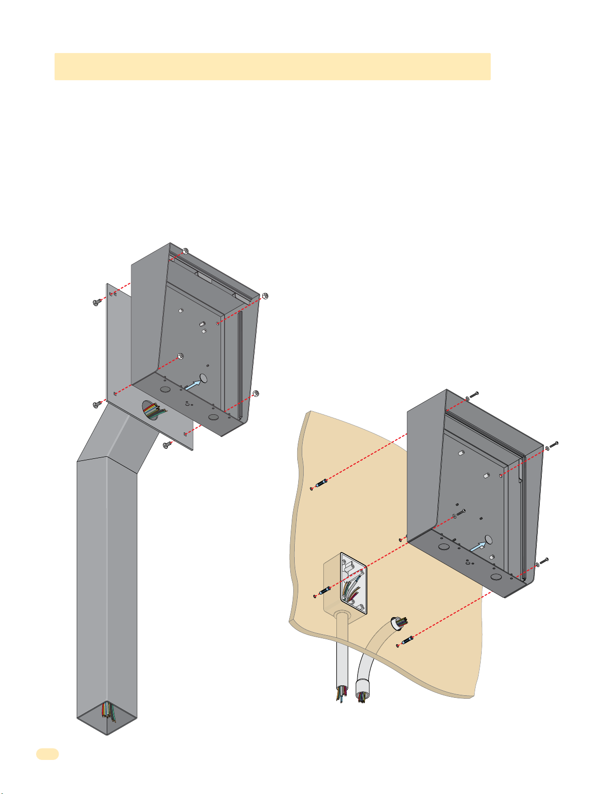
1.1.3 1810 Access Plus Surface Mount Continued
The illustrations below show typical surface mount installations but specific installations can vary from this.
1. Mount the enclosure using the mounting holes provided in the corners. Be sure that mounting screws (Not supplied) do not
protrude into the enclosure where they could cause a short on the back of the circuit board. Make any necessary conduit
connections through the back or bottom of the enclosure using the existing conduit knock-outs. DO NOT make any new conduit
holes in the enclosure.
2. Route all wiring through conduit or architectural post (not supplied) into enclosure.
3. Clean out the enclosure. Make sure that all dirt, metal and/or wood debris is removed.
4. Re-install components back into the enclosure (Reverse section 1.1). Use the wiring schematics in the back of this manual to
help re-install the components if necessary. DO NOT apply any power at this time.
Mount to an
Architectural
Mounting
Post
Mounting Hole
Su
rface Mount
Enclosure
Knock-ou
t
Use hardware supplied with
architectural post to secure
enclosure to post.
Note: An architectural
mounting post anchored
in concrete does not
make a good ground.
Mount ON a Surface
(See sections 1.2).
Wall
Use appropriate
hardware to secure
enclosure to the wall
(not supplied).
Mounting Hole
Surface Mount
Enclosur
e
Knock-out
Conduit run
to junction box
Run all wires
inside post.
10
Examples of conduit runs that may be used, depending on how you choose to run
the wiring. Some installations will allow the conduit to be run outside the wall and
connect to the bottom of the enclosure but this is generally NOT recommended.
Conduit
sweep run
1810-162-A-6-16
Page 15
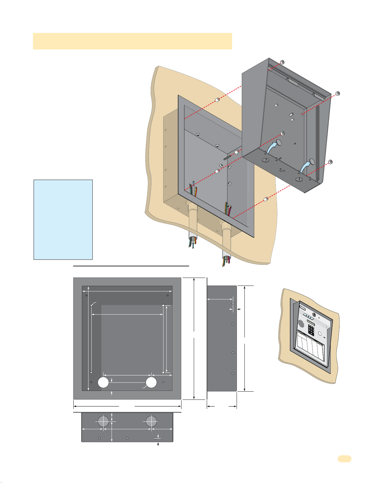
7
8
9
4
5
6
1
2
3
0
1.1.3 1810 Surface Mount Recess Kit
1810 surface mount unit can be recessed
into a wall or pilaster by using the optional
surface mount recess kit if desired (P/N
1803-150). This allows a recessed 1810
telephone entry system to have a lighted
keypad which the flush mount unit DOES
NOT have. The recess box gets installed in
the wall. Use appropriate hardware (not
included) to secure the box in the wall. Run
all necessary conduit (not included) to the
recess box. Slide the enclosure in the recess
box and secure it with the hardware included
in the kit. Be sure the unit is mounted
securely and is not subject to vibration from
closing doors or gates.
WARNING! If this entry
system is used to control a
vehicular gate with an
automatic gate operator, the
entry system must be
mounted a minimum of ten
(10) feet away from the gate
and gate operator, or in
such a way that a person
cannot operate the entry
system and touch the gate
or gate operator at the same
time.
Recess Box
Front View
Mount In a Surface
Wall
Plastic Spacer
Mounting Screws (Not supplied)
Recess
Box
Side View
Locknut
Surface Mount
Enclosure
Knock-outs
1810-162-A-6-16
25” Dia. Mounting Hole
13.25”
1”
1.125”
2.625”
2.5”
Bottom View
11.25”
9”
6”
1.375” Dia.
13.375”
6”
Threaded Stud
2.625”
2.625”
.4”
8.5”
15.25”
3.2”
.4”
Mounting
Holes
.25” Dia.
3.625”
13.25”
1
2
3
4
5
7
6
8
9
0
N
A
M
E
A
d
a
m
s
J
A
k
i
n
s
M
A
n
n
e
s
e
N
C
J
A
A
O
M
n
D
d
E
EN
e
r
s
D
o
o
n
A
0
r
p
H
l
0
a
p
A
9
n
l
M
e
d
g
E
T
D
a
t
o
A
e
1
w
B
u
B
1
y
s
n
5
e
t
w
i
r
n
a
s
D
r
D
M
d
u
B
3
L
b
C
a
5
r
l
a
sb
e
2
r
u
d
a
i
C
i
l
l
u
D
l
O
M
o
g
u
B
D
h
5
P
k
C
a
E
e
5
B
s
a
s
1
s
r
n
D
J
e
E
y
2
n
B
N
P
C
9
g
6
C
e
0
A
O
h
5
j
o
M
a
D
a
6
l
r
r
l
E
E
i
d
n
I
E
s
L
1
l
J
l
B
G
5
i
0
o
s
C
e
2
8
7
r
r
o
W
d
0
l
8
l
i
a
y
n
7
n
e
J
r
F
M
0
a
R
J
B
2
r
2
o
C
a
e
8
5
2
r
g
r
o
d
0
n
1
o
r
en
3
a
d
F
r
u
d
F
l
L
0
a
ar
J
E
B
7
3
o
D
C
r
i
2
l
5
o
2
r
l
o
i
g
0
w
1
n
u
e
1
g
r
n
M
t
s
F
s
E
C
8
e
e
L
K
B
2
O
rn
n
2
C
l
r
8
e
D
4
4
o
B
a
r
i
0
9
E
a
k
n
n
i
4
e
d
n
D
r
e
s
G
T
z
3
G
a
K
B
4
S
0
r
4
D
n
r
2
f
2
4
7
o
s
e
S
B
r
o
w
n
J
B
r
o
w
n
K
B
r
y
a
n
t
W
B
y
ro
n
R
B
y
a
n
G
N
i
o
a
e
3
6
6
b
l
A
l
t
1
d
l
o
M
i
c
n
S
G
E
h
7
a
B
L
3
B
5
rr
0
a
D
3
6
2
0
R
m
e
a
2
4
3
a
e
n
b
9
u
e
i
e
se
B
J
G
l
s
4
e
L
4
D
R
6
n
1
a
D
1
4
7
t
1
R
n
a
r
7
7
2
d
y
e
w
2
i
g
D
M
l
s
e
G
6
r
J
o
L
1
B
7
2
n
a
D
2
3
6
9
R
z
n
e
a
6
3
2
d
e
L
l
3
e
m
e
a
r
z
h
H
s
i
n
a
9
H
a
L
S
e
g
1
4
b
8
a
D
C
t
4
M
0
4
o
e
2
R
n
i
l
2
l
P
4
D
9
i
l
1
l
o
n
M
3
D
2
i
x
4
o
n
D
2
D
3
o
1
m
i
n
3
D
3
o
2
n
i
c
1
D
1
o
7
n
n
D
o
n
t
O
r
8
8
n
g
e
f
D
1
st
e
s
S
E
l
s
d
r
H
e
o
5
g
a
A
L
m
4
8
m
i
e
e
2
0
1
R
v
u
B
m
0
3
0
i
o
n
8
R
4
e
l
e
l
1
r
i
n
H
D
V
1
s
e
L
2
0
n
e
A
0
2
3
d
S
w
1
6
2
r
c
i
i
4
s
2
h
x
8
u
B
K
H
s
7
i
t
L
r
3
e
9
d
u
2
r
9
0
S
c
A
8
S
6
6
i
e
d
8
8
e
i
7
l
e
B
H
y
1
i
i
c
M
t
8
J
3
k
c
6
a
3
8
h
S
P
n
0
8
8
e
J
c
6
8
l
l
i
3
e
n
H
k
c
i
2
k
i
G
M
P
tc
3
4
H
2
a
7
5
h
S
s
8
6
1
h
F
t
8
8
i
a
n
3
e
e
H
r
D
3
r
o
M
R
3
K
1
d
3
a
0
3
S
g
s
5
1
5
e
h
to
5
8
s
a
1
e
n
n
A
H
r
k
8
F
o
D
M
F
3
0
o
5
o
6
4
S
v
7
z
9
6
e
i
i
m
3
r
7
n
1
a
H
o
J
n
3
J
e
M
s
0
n
2
2
s
u
L
4
7
S
e
4
c
7
6
m
n
e
3
5
r
i
5
D
t
a
J
h
0
o
J
M
J
6
h
1
4
n
u
2
9
S
0
s
l
2
5
o
i
o
n
5
4
m
n
5
B
J
a
M
0
o
c
N
0
h
h
0
ab
5
n
4
9
S
H
0
s
0
9
t
o
o
e
8
2
r
e
n
2
l
K
J
e
T
4
o
N
9
F
n
6
a
0
e
4
S
b
s
6
0
t
u
o
5
A
r
l
0
l
J
a
J
3
c
o
N
4
h
n
4
e
1
e
4
S
H
u
s
7
7
y
m
9
G
n
1
a
f
o
n
8
l
n
N
7
A
0
i
J
9
x
0
T
0
o
o
6
2
n
m
1
R
l
i
5
n
P
5
s
7
a
o
7
4
To
t
n
0
t
5
e
7
m
L
r
6
s
p
o
0
s
n
P
3
o
5
e
F
2
n
4
T
r
1
e
o
6
A
0
z
m
0
F
p
4
s
P
1
o
5
e
9
n
0
T
t
3
r
1
y
S
o
3
l
e
l
4
l
r
i
A
Q
R
3
a
3
W
y
2
0
a
J
1
s
3
h
i
n
2
g
1
W
t
o
2
1
a
n
2
s
9
G
h
i
n
5
g
4
W
t
o
0
3
e
n
0
n
7
K
t
L
9
8
Wh
1
7
3
i
4
t
i
n
g
3
M
5
Wi
6
2
0
n
9
s
t
o
n
Wy
F
3
8
a
9
t
t
J
6
7
9
2
1
1
6
7
0
4
4
1
11
Page 16
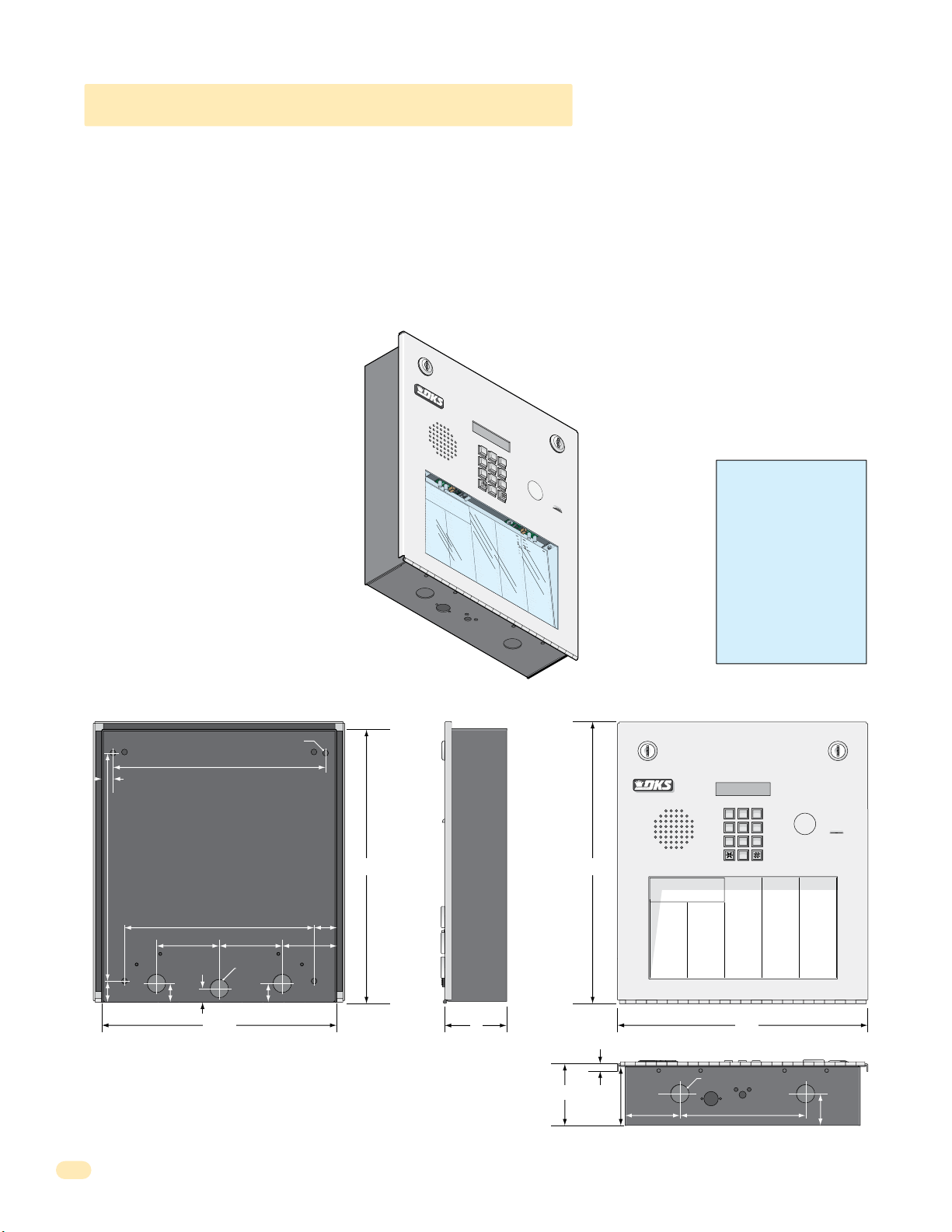
7
8
9
4
5
6
1
2
3
0
Op
er
a
ting Inst
ructions
cate
Code Number On Direct
or
y
ess Co
d
e
Num
ber. I
f Line
Is Busy
, Pr
ess Any Bu
t
ton
Hang-Up.
T
ry
Ag
a
in.
nt
er
On
“OP
EN” Display or
T
one
.
J
M
e
J
so
n
H
e
g
a
te
B
n
D
b
a
u
g
h
B
s
J
a
r
I
rl
in
J
rn
a
r
d
E
llin
g
s
L
ro
k
e
r
T
B
ro
s
e
S
B
ro
wn
J
B
ro
wn
K
B
ry
a
n
t
W
B
y
ro
n
R
B
y
a
n
G
0
0
9
1
1
5
3
5
2
5
5
1
6
5
6
0
7
8
2
2
1
3
2
1
2
4
9
4
7
6
0
0
3
1
1
2
2
9
2
8
2
2
4
9
1
3
2
4
2
3
1
3
3
2
1
1
7
C
OD
E
NAME
B
ye
rs
M
C
ard
i
ll
o
P
C
arn
e
y
P
C
o
l
lin
s
G
C
o
l
y
e
r
R
C
o
rd
u
la
D
C
o
u
rt
E
C
ra
in
s
G
Da
lt
o
n
B
Da
n
i
el
s
R
Dawl
s
J
De
L
a
h
a
e
M
Di
ll
P
Di
l
lo
n
M
Di
x
o
n
D
Do
min
i
c
k
P
Do
n
i
c
k
P
Do
n
n
e
r
K
Do
n
t
e
r
F
8
0
7
5
0
3
5
0
1
4
0
4
4
6
1
2
4
9
7
7
2
6
3
3
4
8
1
1
0
4
3
2
2
0
6
8
8
8
8
5
1
8
3
5
8
4
6
7
7
6
5
9
5
4
9
9
2
C
ODE
NA
M
E
Do
r
l
a
n
d
T
Do
w
n
w
a
rd
L
Du
b
re
u
il
M
Du
k
e
s
D
E
n
g
h
a
r
d
L
E
llis
W
F
a
ra
g
o
F
F
a
rr
o
w
M
F
e
rna
n
d
e
z S
Garf
ie
l
d
S
Garrea
u
J
Gen
tr
y
M
Go
n
za
lez
H
Hab
e
r
f
e
ld
A
Hamme
r
V
He
n
d
r
i
x
K
Hir
d
A
Hit
c
h
J
Hit
c
h
F
Ho
d
g
es
A
Ho
o
v
e
r
H
J
e
n
s
e
n
D
J
o
h
n
s
o
n
M
J
o
h
n
s
o
n
T
J
o
n
e
s
A
J
o
n
e
s
G
2
9
0
1
5
2
0
2
8
0
7
2
8
2
8
3
4
2
7
3
3
44
1
6
1
2
9
1
4
5
4
2
1
2
0
7
3
2
1
8
6
2
3
2
3
3
3
8
3
5
3
0
2
0
6
4
0
0
5
4
9
0
3
4
1
8
7
9
5
5
7
0
3
2
4
1
9
C
ODE
N
A
ME
J
o
rd
an
M
J
o
rd
en
L
J
o
rg
en
s
e
n
B
K
l
e
i
n
D
K
n
o
b
li
c
h
B
L
a
mb
B
L
a
n
d
D
L
a
n
d
e
rs
S
L
a
n
g
s
tr
o
m
B
L
e
v
in
e
D
L
e
w
is
B
L
u
c
id
i
B
Ma
n
c
in
i
G
Ma
sti
n
D
Ma
s
t
o
n
F
Mo
zi
n
a
J
Muc
e
r
a
J
Mulin
B
N
a
b
o
r
K
N
a
b
u
r
J
N
e
u
m
a
n
n
J
N
ix
o
n
R
P
at
t
e
r
s
o
n
F
P
erez F
Pe
t
ro
ll
i
A
R
a
y
J
0
2
6
9
9
6
3
3
8
4
7
6
1
0
1
0
6
9
2
4
7
1
2
2
0
4
0
6
4
0
4
4
7
0
0
6
7
4
5
5
4
6
5
0
1
3
3
0
2
1
1
5
4
3
9
8
7
3
5
2
R
e
s
s
e
g
ie
u
R
R
o
l
l
in
s
A
S
ch
u
st
e
r
S
S
ee
le
y
J
Se
l
le
c
k
H
S
h
ae
r
R
S
h
a
n
k
D
Simo
n
s
L
S
mit
h
J
S
o
m
a
c
h
H
St
e
e
le
F
S
t
o
lla
c
h
H
S
yn
fo
l
A
T
o
ml
i
n
s
o
n
L
T
o
mps
o
n
A
T
o
mps
o
n
S
Ty
le
r
Q
W
a
s
h
in
g
t
o
n
G
W
a
s
h
in
g
to
n
K
W
e
n
t
L
W
h
it
in
g
M
W
in
st
o
n
F
W
y
a
t
t
J
0
8
1
1
4
8
8
8
7
0
6
3
8
8
3
5
5
1
7
3
1
4
3
5
0
5
5
0
8
2
6
5
0
7
9
1
0
2
1
0
7
6
1
0
0
3
3
4
2
1
3
2
2
9
0
0
7
1
3
4
6
0
9
3
8
9
6
7
9
2
1
1
6
7
0
4
4
1
1.1.4 1810 Access Plus Flush Mount
9
6
3
0
Flush mount 1810 is installed with a flush mount kit P/N 1814-165 (stainless) or 1814-166 (gold). Flush mount kits are NOT
INCLUDED with the flush mount entry system (See next page for flush mount kit installation).
The flush mount units may also be installed ON the surface of a wall with a flush mount surface mounting kit if desired P/N
1814-152 (silver only). Flush mount surface mounting kits are NOT INCLUDED with the flush mount entry system (See page 14
for flush mount surface mounting kit installation).
DoorKing offers a self-standing lighted kiosk for the flush mount unit ideal for walk-up pedestrian applications P/N 1200-170
(See page 15 for self-standing kiosk installation).
Flush mount 1810 is installed into a wall/kiosk and can be mounted outside, exposed to the weather. It is preferred that they
have limited direct exposure to the weather. We suggest that when they are mounted outdoors, it is in a covered protected area.
Be sure the unit is mounted securely and is
not subject to vibration from closing doors
or gates.
The flush mount unit DOES NOT have a
lighted keypad.
1
2
3
4
5
7
Creating Printed Directories for 1810 unit:
The Access Plus Account Manager software
will print a directory for the 1810 Access
Plus. The directory can then be easily
inserted into the unit’s directory slot.
6
1
.
Lo
Op
cate
2
.
P
er
Code Number On Direct
ress Co
a
ting Inst
to Hang-Up.
d
3.
e
En
Num
t
er
ber. I
On
NA
T
ry
ME
Ag
“OP
f Line
A
a
d
EN” Display or
in.
a
ms
J
A
k
in
s
M
A
n
n
e
s
e
J
A
C
n
OD
d
e
E
rs
o
n
A
H
p
p
0
l
0
e
9
g
a
te
A
u
B
s
1
t
1
i
n
5
D
B
a
ls
3
5
b
2
a
u
g
B
h
a
B
s
5
s
5
1
J
B
e
ja
6
5
r
6
I
B
e
rl
0
in
7
8
J
B
e
rn
2
2
a
1
r
d
E
B
i
llin
3
2
g
1
s
L
B
ro
2
k
4
e
9
r
T
B
ro
4
s
7
e
S
B
ro
0
wn
0
J
B
ro
1
wn
K
B
ry
2
a
n
t
W
B
y
ro
8
n
R
B
y
a
n
G
1810 Flush Mount
8
9
0
ructions
or
y
Is Busy
, Pr
ess Any Bu
T
NA
one
M
E
.
Do
r
NAME
l
a
t
n
ton
d
T
Do
w
B
n
ye
w
rs
a
Du
rd
M
L
b
C
re
ard
u
il
i
Du
ll
M
C
o
ODE
P
k
C
e
arn
s
D
e
E
y
n
g
P
2
C
o
l
lin
C
o
l
y
C
o
rd
C
o
C
ra
Da
6
Da
3
Dawl
1
2
9
2
2
2
4
9
1
3
2
4
2
3
1
3
3
2
1
1
7
N
h
9
C
a
A
0
ODE
r
ME
d
E
L
s
llis
G
1
J
5
W
o
2
rd
8
0
e
r
R
u
la
u
rt
E
in
s
lt
o
n
n
i
el
s
De
L
a
Di
ll
P
Di
l
lo
Di
x
Do
Do
Do
Do
an
F
7
a
M
ra
0
J
2
g
o
8
o
rd
5
F
0
en
F
3
a
L
rr
0
D
J
o
7
o
w
2
rg
5
M
0
en
F
1
e
s
rna
8
e
K
2
n
8
l
n
e
B
4
d
i
n
0
e
Garf
4
z S
G
B
s
R
J
h
a
e
n
M
o
n
D
min
n
i
c
k
n
n
e
n
t
e
D
3
K
4
ie
2
n
l
4
d
o
6
S
b
Garrea
1
li
c
7
h
L
3
B
a
3
mb
2
u
4
J
Gen
9
B
44
L
tr
a
1
y
n
7
M
d
7
Go
2
D
6
n
L
1
za
a
2
lez
n
6
d
3
Hab
e
3
H
rs
9
M
i
c
k
P
r
r
L
e
S
1
r
a
4
f
n
4
e
g
8
ld
Hamme
1
1
0
He
4
n
d
3
2
Hir
2
d
0
6
Hit
8
c
P
8
8
Hit
8
5
1
Ho
8
K
3
5
Ho
8
F
4
6
J
7
e
7
6
J
5
9
5
J
4
9
9
2
R
s
A
tr
e
s
5
o
s
L
4
m
e
e
2
g
B
v
ie
in
r
R
V
e
o
D
l
1
l
in
L
2
e
r
0
i
x
K
A
h
J
c
h
F
d
g
es
o
v
e
r
n
s
e
n
o
h
n
s
o
h
n
s
J
o
n
e
J
o
n
e
s
w
0
2
is
S
6
ch
B
7
u
L
3
st
u
2
c
9
id
9
S
6
i
ee
B
1
le
Ma
8
y
6
3
n
3
c
Se
8
in
l
i
2
le
G
Ma
3
c
2
4
sti
7
S
6
n
h
ae
D
3
Ma
3
r
3
1
s
0
t
A
S
o
1
h
n
a
8
F
n
Mo
3
5
0
zi
H
6
Simo
n
9
a
3
J
Muc
0
2
2
D
4
e
S
7
r
mit
a
0
J
Mulin
6
4
o
1
n
2
S
M
2
B
o
m
0
N
0
5
a
o
b
0
n
o
4
St
r
T
0
e
K
4
N
9
s
0
a
A
b
6
u
4
S
r
0
t
o
J
3
N
4
s
1
e
G
u
4
m
4
S
7
a
yn
n
8
n
N
7
9
ix
J
0
o
0
n
T
6
o
R
5
P
5
7
at
7
t
e
4
T
r
5
s
o
0
n
P
3
2
erez F
F
5
4
T
6
4
Pe
1
9
t
5
ro
0
1
ll
i
A
R
a
y
3
3
J
0
2
1
1
5
4
3
9
8
7
3
5
2
u
R
0
8
1
A
1
4
8
e
r
S
8
8
7
J
0
6
3
k
H
8
8
3
R
5
5
k
1
D
7
3
n
1
s
L
4
3
h
5
J
0
5
a
5
c
h
H
0
e
8
le
2
F
6
lla
5
0
c
h
H
7
fo
9
1
l
A
ml
0
2
i
1
n
s
o
n
o
mps
L
0
7
6
o
n
o
A
mps
1
0
0
o
n
Ty
S
le
3
r
3
4
Q
W
a
2
s
1
h
3
in
g
W
t
o
a
n
2
s
G
2
h
9
in
g
W
to
e
n
0
n
K
0
t
7
L
W
h
1
it
3
in
4
g
M
W
in
6
st
0
9
o
n
W
F
y
3
a
8
t
t
9
J
6
7
9
2
1
1
6
7
0
4
4
1
WARNING! If this entry
system is used to control a
vehicular gate with an
automatic gate operator, the
entry system must be
mounted a minimum of ten
(10) feet away from the gate
and gate operator, or in
such a way that a person
cannot operate the entry
system and touch the gate
or gate operator at the same
time.
10.875”
1”
.5”
25” Dia. Mounting Hole
10.125”
9”
3”
.5”
.875”
3”
.875” Dia
.875”
11.25”
2.625”
1.125”
Side ViewBack View Front View
11223
44556
77889
0
13.5”13”
Operating Instructions
1. Locate Code Number On Directory
2. Press Code Number. If Line Is Busy, Press Any Button
to Hang-Up. Try Again.
3. Enter On “OPEN” Display or Tone.
NAME
CODE NAME
Adams J
009
Byers M
Akins M
115
Cardillo P
Annese J
352
Carney P
Anderson H
551
Collins G
Applegate B
656
Colyer R
Austin D
078
Cordula D
Balsbaugh B
221
Court E
Bass J
321
Crains G
Bejar I
249
Dalton B
Berlin J
476
Daniels R
Bernard E
003
Dawls J
Billings L
112
DeLahae M
Broker T
292
Dill P
Brose S
822
Dillon M
Brown J
491
Dixon D
Brown K
324
Dominick P
Bryant W
231
Donick P
Byron R
332
Donner K
Byan G
117
Donter F
3”
CODE NAME
NAME
Jordan M
Dorland T
290
Jorden L
Downward L
152
Jorgensen B
Dubreuil M
028
Klein D
Dukes D
072
Knoblich B
Enghard L
828
Lamb B
Ellis W
342
CODE
733
Land D
Farago F
807
441
Landers S
Farrow M
503
612
Langstrom B
Fernandez S
501
914
Levine D
Garfield S
404
542
Lewis B
Garreau J
461
120
Lucidi B
Gentry M
249
732
Mancini G
Gonzalez H
772
186
Mastin D
Haberfeld A
633
232
Maston F
Hammer V
481
333
Mozina J
Hendrix K
104
835
Mucera J
Hird A
322
302
Mulin B
Hitch J
068
064
Nabor K
Hitch F
888
005
Nabur J
Hodges A
518
490
Neumann J
Hoover H
358
341
Nixon R
Jensen D
467
879
Patterson F
Johnson M
765
557
Perez F
Johnson T
954
032
Petrolli A
Jones A
992
419
Ray J
Jones G
12”
.25”
.875” Dia
3”
2.75”
2.625”
6”
Bottom View
CODE NAME
023
562
647
736
408
803
026
996
338
476
101
069
247
122
040
640
447
006
745
546
501
330
211
543
987
352
CODE
Reese D
081
Reiger B
148
Remington S
887
Ressegieu R
063
Rollins A
883
Schuster S
551
Seeley J
731
Selleck H
435
Shaer R
055
Shank D
082
Simons L
650
Smith J
791
Somach H
021
Steele F
076
Stollach H
100
Synfol A
334
Tomlinson L
213
229
Tompson A
007
Tompson S
134
Tyler Q
609
Washington G
389
Washington K
679
Went L
211
Whiting M
670
Winston F
441
Wyatt J
1.5”
12
1810-162-A-6-16
Page 17
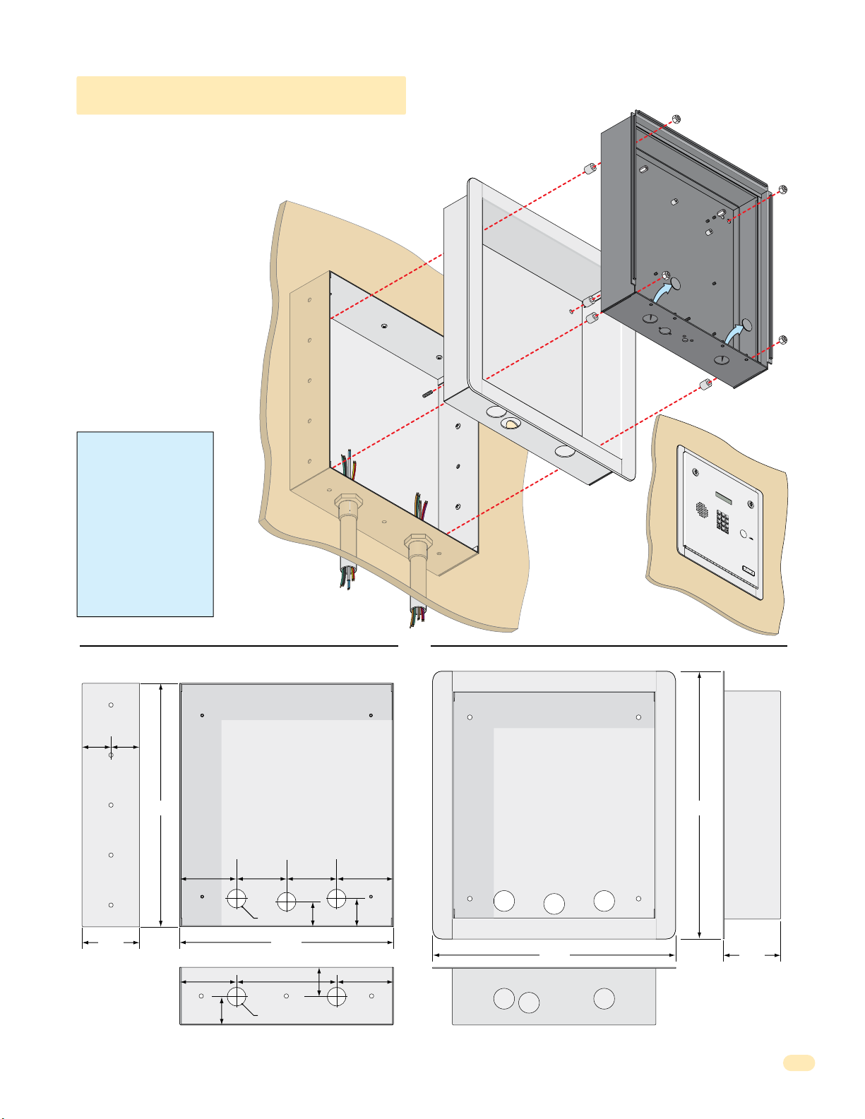
7
8
9
4
5
6
1
2
3
0
O
P
E
R
W
X
Y
Z
TU
V
P
Q
R
S
M
N
O
J
K
L
G
H
I
D
E
F
A
B
C
S
P
1.1.4 1810 Flush Mount Kit
The flush mount kit has two
parts; the rough-in box and the
trim ring. The rough-in box is
installed in the wall first. Use
appropriate hardware (not
included) to secure the box in the
wall. Run all necessary conduit
(not included) to rough-in box.
Slide the trim ring into the
rough-in box. Slide the enclosure
in the trim ring and secure them
all together with the hardware
included in the kit. Be sure the
unit is mounted securely and is
not subject to vibration from
closing doors or gates. See
previous page for flush mount
enclosure dimensions.
WARNING! If this entry
system is used to control a
vehicular gate with an
automatic gate operator, the
entry system must be
mounted a minimum of ten
(10) feet away from the gate
and gate operator, or in
such a way that a person
cannot operate the entry
system and touch the gate
or gate operator at the same
time.
Mount In a Surface
Wall
Rough-In
Box
Mounting Screws
(Not supplied)
Plastic Spacer
Trim
Ring
Locknut
Flush Mount
Enclosure
Knock-outs
T
E
L
E
PH
O
NE
E
N
T
RY
SYS
S
P
1
A
B
C
2
D
G
E
H
F
I
3
4
J
K
L
5
P
M
Q
N
R
O
S
6
7
TU
V
8
W
X
Y
Z
9
OP
E
R
0
O
1.
PE
Loc
R
2.
at
A
P
e
T
re
C
I
ode
N
s
s
P
G
C
re
I
o
Nu
3.
s
de
NST
s
m
Enter
“#”
N
ber
um
R
t
on
ber
UCT
on
o
H
D
.
T
ang
irec
one.
I
f
Line
U
t
P.
i
T
s
r
y
A
g
ai
T
E
M
I
O
N
or
S
y
.
B
us
y
,
n.
M
ODE
L
1
8
0
3
Side View
1.74” 1.71”
Mounting
Holes
.25” Dia.
3.45”
Rough-In Box Trim Ring
Front View
Threaded Stud
14.6” 16”
1.5”
3.4”
1.685”
Mounting
Hole
3.4”
3”
3”
1.125” Dia
12.8”
3.4” 3.4”
1.74”
6”
1.8”
1.125” Dia
Front View
Hole for Threaded Stud
14.7”
Bottom ViewBottom View
Side View
3.45”
1810-162-A-6-16
13
Page 18
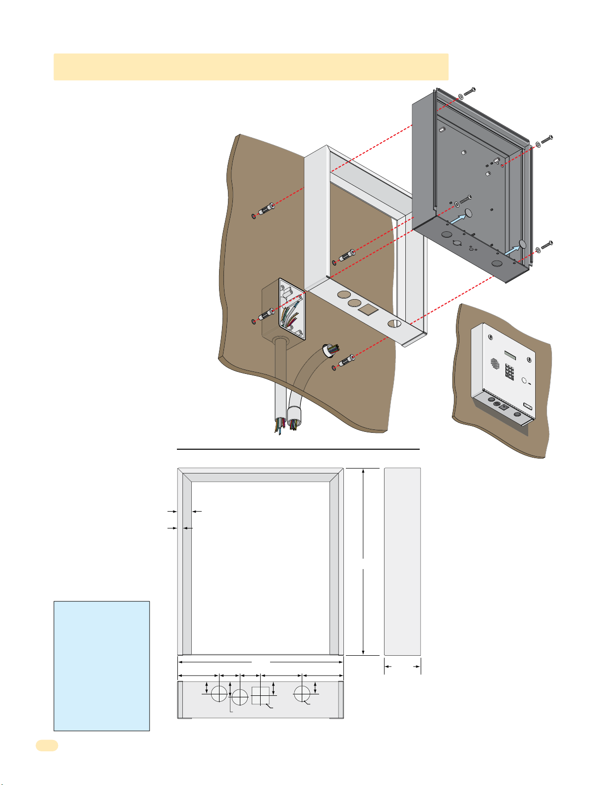
7
8
9
4
5
6
1
2
3
0
O
P
E
R
W
X
Y
Z
T
U
V
P
Q
R
S
M
N
O
J
K
L
G
H
I
D
E
F
A
B
C
S
P
1.1.4 1810 Flush Mount Surface Mounting Kit
Flush mount unit can be mounted ON a
wall or pilaster and NOT IN the wall by
using the optional flush mount surface
mounting kit (P/N 1814-152). This is
useful when cutting a large hole into a wall
or pilaster would be very difficult (marble
or granite for example). The flush mount
surface mounting kit is a trim ring that fits
around the flush mount enclosure. The
enclosure and trim ring get installed
directly on the wall using appropriate
hardware (not included) after running all
necessary conduit to the enclosure. Be
sure the unit is mounted securely and is
not subject to vibration from closing
doors or gates.
The flush mount unit DOES NOT have a
lighted keypad.
Examples of some
small holes in the
wall that may be
needed, depending
on how you choose
to run the wiring.
to junction box
Trim Ring
Mount On a Surface
Wall
Trim Ring
Conduit run
Conduit
sweep
run
Mounting Screws
(Not supplied)
Flush Mount
Enclosure
Knock-outs
T
E
L
E
PH
O
1.
PE
Loc
2.
at
P
e
re
s
s
P
re
3.
s
s
Enter
O
NE
E
N
T
RY
SYST
E
M
S
P
1
A
B
C
2
DE
GH
F
I
3
4
J
K
L
5
P
MN
Q
R
O
S
6
7
TU
V
8
WX
Y
Z
9
O
P
E
R
0
R
A
T
C
I
ode
N
G
C
I
o
Nu
de
NST
m
“#”
N
ber
um
R
t
on
ber
UCT
on
o
H
D
.
T
ang
irect
one.
I
f
I
O
Line
U
N
or
P.
S
y
i
.
Tr
s
y
B
A
us
gain.
y
,
M
ODEL
1
8
0
3
WARNING! If this entry
system is used to control a
vehicular gate with an
automatic gate operator, the
entry system must be
mounted a minimum of ten
(10) feet away from the gate
and gate operator, or in
such a way that a person
cannot operate the entry
system and touch the gate
or gate operator at the same
time.
14
.375”
.875”
1”
12”
1.5”
1.5”3” 3” 3”
1.125”
1.125” Sq
Bottom View
Side ViewFront View
13.5”
2.625”
1”
.875”
1.125” Dia
1810-162-A-6-16
Page 19
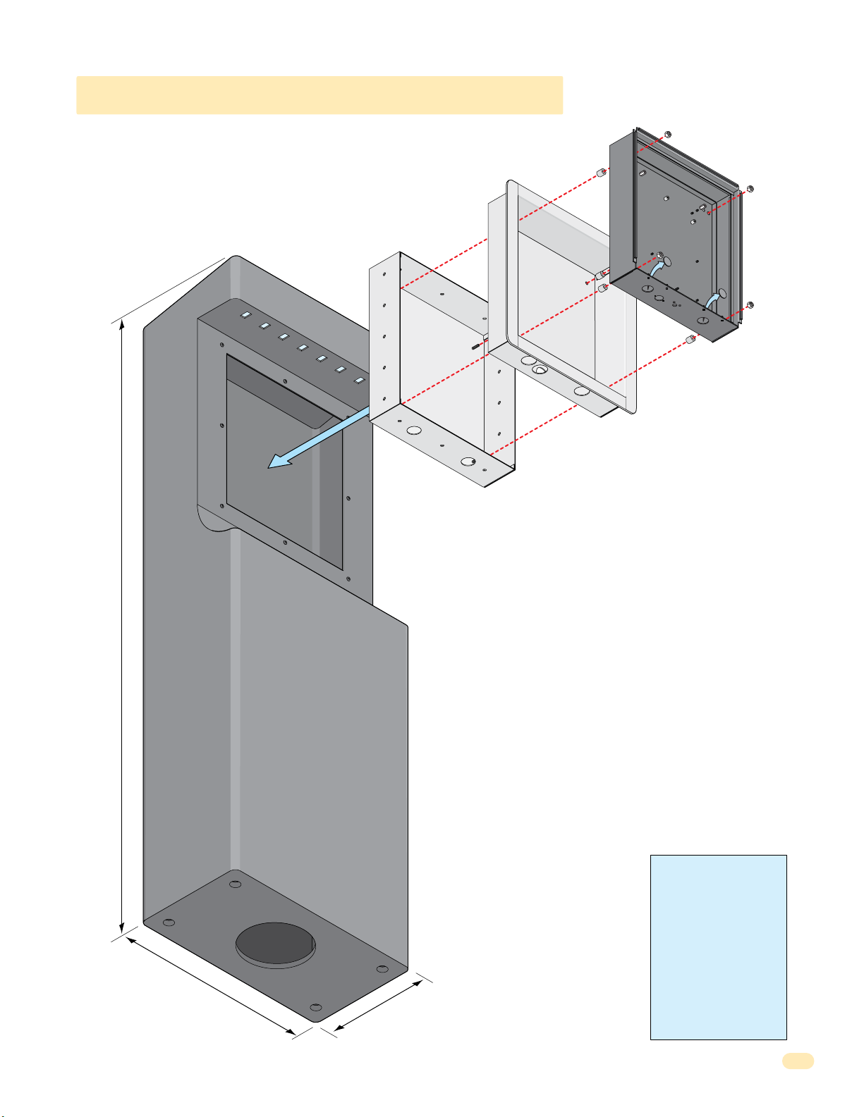
1.1.4 1810 Self-Standing Lighted Kiosk
The flush mount kit (Sold separately, see previous page) is installed into
the self-standing kiosk (P/N 1200-170) to secure the flush mount 1810
in place.
Secure the rough-in box in the kiosk. Run all necessary wires to
rough-in box. Slide the trim ring into the rough-in box. Slide the
enclosure in the trim ring and secure them all together with hardware
included in the kit.
Rough-In
Box
Plastic Spacer
Trim
Ring
Locknut
Flush Mount
Enclosure
Knock-
outs
60”
18
.5”
10
WARNING! If this entry
system is used to control a
vehicular gate with an
automatic gate operator, the
entry system must be
mounted a minimum of ten
(10) feet away from the gate
and gate operator, or in
such a way that a person
cannot operate the entry
”
system and touch the gate
or gate operator at the same
time.
1810-162-A-6-16
15
Page 20
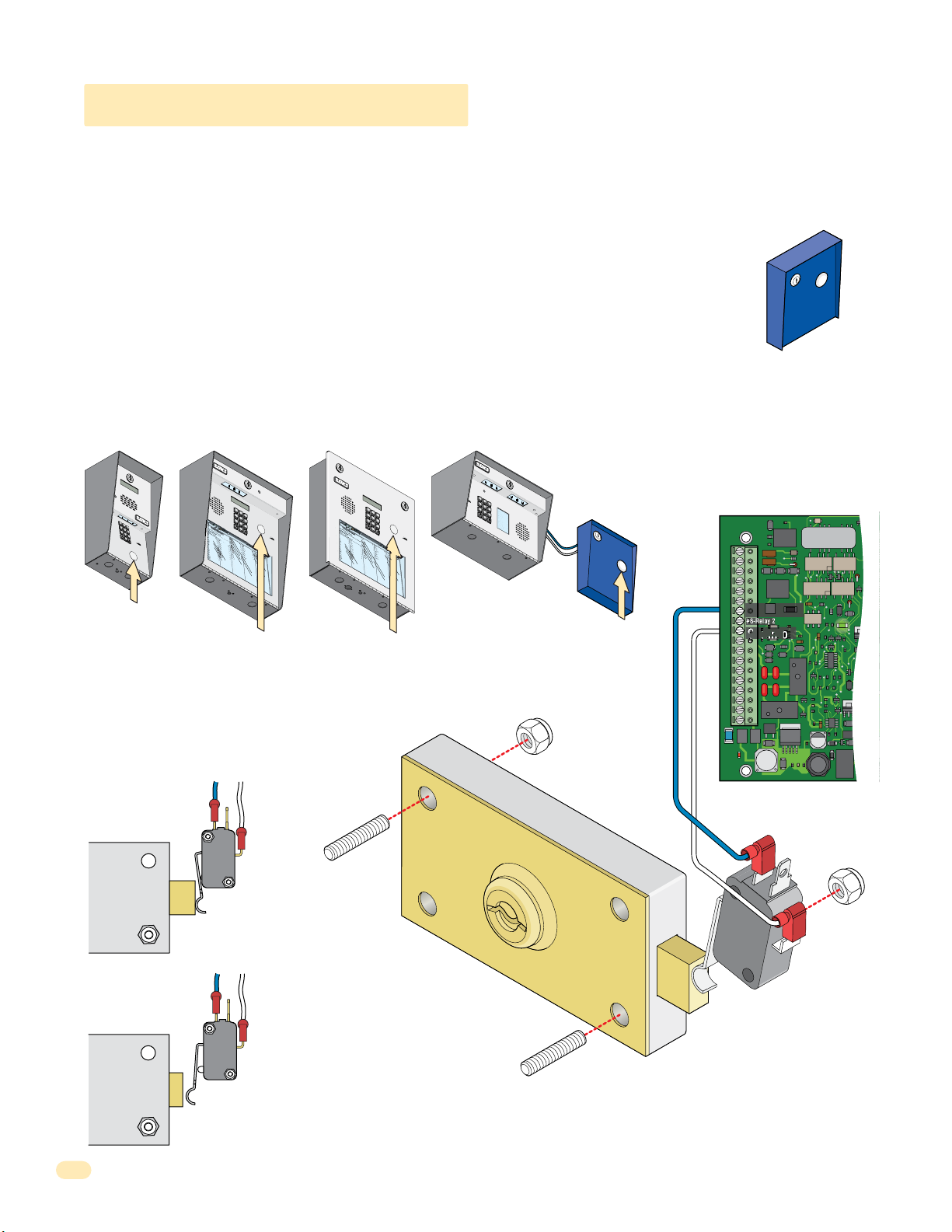
7
8
9
4
5
6
1
2
3
0
1.2 Postal Lock Installation
7
8
9
4
5
6
1
2
3
0
2
3
1
33
2
11
7
D
i
x
on
D
D
o
m
i
ni
c
k
P
D
oni
c
k
P
D
o
nne
r
K
D
ont
e
r
F
32
2
068
8
8
8
518
3584
67
76
5
954
99
2
H
e
ndr
i
x
K
H
i
r
d
A
H
i
t
c
h
J
H
i
t
c
h
F
H
o
d
g
e
s
A
H
oo
v
e
r
H
J
e
ns
e
n
D
J
oh
ns
on
M
J
ohns
o
n
T
J
on
e
s
A
J
on
e
s
G
7
32
18
6
2
32
333
8353
02
06
4
00
5
49
0
3
41
8
7
9
5
57
0
32
419
L
e
w
i
s
B
L
uc
i
d
i
B
M
a
n
c
i
ni
G
M
a
s
t
i
n
D
M
a
s
t
o
n
F
M
oz
i
na
J
M
u
c
e
r
a
J
M
ul
i
n
B
N
a
bo
r
K
N
a
bu
r
J
N
e
um
a
nn
J
N
i
x
o
n
R
Pa
t
t
e
r
s
on
F
P
e
r
e
z
F
P
e
t
r
o
l
l
i
A
R
a
y
J
026
9
9
6
3
38
4
7
6
101
0
6
9
2
47
12
2
0406
40
44
7
00
6
745
546
50
1
33
0
2
1
1
5
4
3
98
7
352
R
o
l
l
i
ns
A
S
c
h
us
t
e
r
S
S
e
e
l
e
y
J
Se
l
l
e
c
k
H
S
h
a
e
r
R
Sh
a
nk
D
S
i
m
o
n
s
L
S
m
i
t
h
J
S
o
m
a
c
h
H
S
t
e
e
l
e
F
S
t
ol
l
a
c
h
H
S
y
n
f
o
l
A
To
m
l
i
n
s
on
L
T
o
m
ps
on
A
T
om
ps
o
n
S
T
y
l
e
r
Q
W
a
s
hi
ng
t
on
G
W
a
s
hi
n
g
t
o
n
K
W
e
nt
L
W
hi
t
i
ng
M
W
i
ns
t
o
n
F
W
y
a
t
t
J
148
8
87
06
3
883
551
7
31
435
0
5
5
08
2
650
79102
1
076100
334
2
13
22
9
0
0
7
1
3
4
6
0
9389
67
9
2
11
6
7
0
44
1
7
8
9
4
5
6
1
2
3
0
NAME
Ada
ms
J
Bern
a
r
d
E
Brow
n
L
Da
vi
s T
Hodge
s S
Mil
ler
J
Smith
K
Tho
ma
s
W
Z
im
me
r
R
1
9
5
2
4
6
8
3
7
C
ODE
7
8
9
4
5
6
1
2
3
0
3
2
4
2
3
1
3
3
2
1
1
7
D
il
l
o
n
M
D
i
x
o
n
D
D
o
m
i
n
i
c
k
P
D
o
n
ic
k
P
D
o
n
n
e
r
K
Do
n
te
r
F
1
0
4
3
2
2
0
6
8
8
8
8
5
1
8
3
5
8
4
6
7
76
5
9
5
4
9
9
2
H
a
m
m
e
r
V
H
e
n
d
r
i
x
K
H
i
r
d
A
H
i
tc
h
J
H
it
c
h
F
H
o
dg
e
s
A
H
o
o
v
e
r
H
J
e
n
s
e
n
D
J
o
h
n
s
on
M
J
o
hn
s
o
n
T
J
o
n
e
s
A
J
o
n
e
s
G
1
2
0
7
3
2
1
86
2
3
2
3
3
3
8353
0
2
0
6
4
0
0
5
4
9
0
3
4
1
8
79
5
5
7
0
3
2
4
1
9
L
e
v
i
n
e
D
L
e
w
is
B
L
uc
i
d
i
B
M
a
n
c
i
n
i
G
M
a
s
t
in
D
M
a
s
t
on
F
M
o
z
i
n
a
J
M
uc
e
r
a
J
M
u
l
i
n
B
N
a
b
o
r
K
N
a
b
u
r
J
N
e
u
m
a
n
n
J
N
ix
o
n
R
P
a
t
t
e
r
s
o
n
F
P
e
r
e
z
F
P
e
tr
o
ll
i
A
R
a
y
J
8
0
3
0
2
6
99
6
33
8
4
7
6
10
1
0
6
9
2
4
7
1
2
2
0
4
0
6
4
0
4
4
7
0
0
6
7
4
5
5
4
6
5
0
1
3
3
0
2
1
1
5
4
3
9
8
7
3
5
2
R
e
s
s
e
g
ie
u
R
R
ol
li
n
s
A
S
c
h
u
s
t
e
r
S
S
e
e
le
y
J
S
e
l
l
e
c
k
H
S
h
a
e
r
R
S
h
a
n
k
D
S
i
m
o
n
s
L
S
m
i
t
h
J
S
o
m
a
c
h
H
S
te
e
l
e
F
S
to
l
l
a
c
h
H
S
y
n
fo
l
A
T
o
m
li
n
s
o
n
L
T
o
m
p
s
o
n
A
T
o
m
p
s
o
n
S
T
y
le
r
Q
Wa
s
h
i
n
g
t
on
G
Wa
s
h
i
n
g
t
on
K
We
n
t
L
W
h
i
t
in
g
M
W
in
s
t
o
n
F
W
y
a
tt
J
0
8
1
1
4
8
8
8
7
0638
8
3
5
5
1
7
3
1
4
3
5
0
5
5
082
65
0
7
9
1
0
2
1
0
7
6
1
0
0
3
3
4
2
1
3
2
2
9
0
0
7
1
3
4
6
0
9
3
8
9
6
79
2
1
1
6
7
0
4
41
At some locations, such as gated communities, it will be necessary to provide access to the mail carrier so that they can
deliver the mail. Mail carrier access will be provided by the installation of an Arrow Postal Lock. This is the same lock that the
Post Office uses for gang mailboxes. These locks are not available to the public. The installer or the building owner/manager
will have to call the Post Office and arrange for the installation of this lock into the access plus system. DoorKing 1802 & 1810
access plus systems are designed to accept installation of the postal lock. If you are using the 1808 and need postal service
access, use the DoorKing Postal Lock Box wired to #7 & #9 shown below, P/N 1402-080 postal box sold separately.
Prior to installation of the postal lock, be sure power to the access plus system is turned OFF.
1. Remove the hole plug on the faceplate of the telephone entry system.
2. Cut the wire tie wrapped around the switch ONLY when installing postal lock.
POSTAL
CK BOX
LO
3. Remove the two hex nuts from the postal lock-mounting studs. Mount postal lock on the studs and secure with the hex nuts.
When the lock is installed, the pawl of the lock, in the extended position is depressing the switch. When the mail carrier inserts
his key and turns the postal lock, the pawl is withdrawn into the lock and the switch will activate Relay 1 for the programmed
strike time. Note: Postal switch can activate Relay 2 when connected to #8 & #9 if desired.
1
2
3
4
5
7
6
1808
NAME
Ada
8
ms
C
Bern
ODE
J
9
a
r
Brow
d
E
1
n
Da
0
L
vi
9
s T
Hodge
5
Mil
s S
ler
2
Smith
J
4
Tho
K
ma
6
Z
s
im
W
me
8
r
R
3
7
POSTAL
LOCK BOX
Postal Box
Hole Plug
g
g postal
n
n
Existi
1970-010
J1
1
2
3
4
5
6
7
8
9
10
11
12
13
14
15
16
17
18
OV
#7-Relay 1
#8-Relay 2
Common
J4
1
2
3
4
5
6
7
8
lock-mounti
nuts.
1
2
3
4
5
7
1
2
3
4
5
6
7
8
9
OPE
INS
RATIN
0
1.
Lo
T
R
c
UC
a
G
D
t
e
i
TION
r
2
Code
e
.
ct
Pres
o
ry
S
N
s
.
If
u
Code
mber o
Li
n
e
B
N
ut
i
s
t
u
on
B
n
mb
Try Aga
us
to
y
er
3
,
H
.
P
.
E
ang
r
n
e
in
te
ss
.
r
U
A
o
p
ny
n
.
T
o
n
e
.
Hole Plug
1802
6
8
1
9
2
0
3
N
A
ME
H
R
e
o
ndr
l
D
l
L
i
ns
i
e
x
i
w
32
x
on
026
A
i
K
H
s
S
2
D
i
c
B
r
h
7
d
2
3
1
33
11
1810 Surface Mount
148
D
us
L
32
A
o
uc
t
m
068
9
e
i
r
9
d
i
H
S
ni
6
i
S
i
e
t
B
c
c
e
18
8
k
D
h
l
M
87
e
P
oni
6
2
y
J
a
8
3
n
J
8
38
c
c
H
Se
8
k
i
i
ni
t
P
c
l
2
06
l
D
h
e
G
M
32
c
o
7
3
F
a
k
nne
518
4
s
H
7
t
H
S
i
6
n
o
r
h
d
D
333
a
K
883
D
g
e
M
ont
r
e
a
s
35
R
101
s
A
t
e
H
Sh
o
8
r
oo
n
F
8
a
551
F
v
nk
M
35
e
oz
r
4
0
D
H
67
6
i
J
S
na
9
e
i
ns
m
3
7
J
M
02
o
31
e
n
n
u
76
s
2
c
D
47
e
L
J
S
5
r
oh
m
a
06
435
J
ns
i
M
t
h
4
ul
on
954
J
12
i
n
J
S
M
2
ohns
o
B
00
m
0
N
5
a
5
a
5
o
c
99
bo
04
h
n
J
S
H
2
T
r
0
on
t
K
e
49
08
e
e
N
l
s
e
0
a
2
A
bu
F
6
40
J
S
r
on
t
J
ol
3
650
e
N
l
41
s
a
e
c
G
um
h
44
S
H
7
a
y
nn
n
8
79
f
N
7
o
9
i
J
1
l
x
00
A
o
n
To
6
R
m
5
02
Pa
57
l
i
n
1
t
s
745
t
e
on
T
r
o
s
on
m
L
0
07
P
32
ps
e
F
6
r
on
546
e
z
T
om
A
F
419
100
P
ps
e
t
o
50
r
o
n
T
l
1
y
l
S
i
l
e
A
334
R
r
a
Q
y
33
J
W
0
a
2
s
13
hi
ng
2
1
W
t
1
on
a
22
s
G
hi
9
n
5
g
4
W
t
3
o
e
n
0
nt
K
0
7
L
98
W
7
hi
1
t
3
i
ng
4
352
M
W
i
ns
6
0
t
9
o
n
W
F
y
38
a
t
t
9
J
67
9
2
11
6
7
0
44
1
Hole Plug
1
2
3
4
5
7
6
8
1
9
2
0
3
H
R
a
e
m
s
D
s
L
m
e
il
e
g
l
v
1
e
o
8
ie
i
r
0
n
n
0
H
R
4
V
u
e
3
M
e
ol
R
D
n
1
3
2
4
2
3
1
3
3
2
1
1
7
0
li
D
d
L
2
8
n
i
r
e
0
1
x
s
i
w
3
x
o
0
A
2
n
is
2
K
H
S
2
6
B
D
i
c
r
h
7
d
1
D
u
L
3
4
A
o
s
uc
2
8
t
m
0
99
e
i
6
r
d
i
H
S
n
8
6
i
S
i
e
i
tc
B
c
e
1
8
k
D
le
h
M
86
8
P
o
y
7
J
a
n
8
33
n
J
ic
8
c
H
S
8
k
8
i
it
n
e
P
l
c
i
2
06
l
D
e
h
G
M
3
c
o
2
3
F
a
k
n
5
4
s
n
1
H
7
t
H
S
e
in
8
6
o
r
h
dg
a
D
3
K
8
Do
e
M
3
8
r
e
3
3
a
n
s
3
R
10
s
te
5
A
t
H
S
on
8
r
1
o
h
F
o
a
83
5
F
n
v
M
5
e
k
5
1
o
r
4
0
D
z
H
6
6
i
J
S
n
7
9
e
a
i
m
n
3
7
J
s
M
0
o
3
e
2
n
1
n
uc
76
s
2
D
4
e
L
J
S
5
7
r
o
m
a
h
0
4
J
i
n
M
6
t
3
h
s
4
5
on
u
9
J
1
l
5
i
2
n
J
S
4
M
2
o
o
B
hn
m
0
0
N
0
5
a
s
5
a
5
c
o
9
b
0
h
n
9
o
4
J
S
H
2
T
r
0
o
te
K
n
4
082
e
e
N
9
l
s
e
0
a
A
b
F
6
u
4
J
S
r
0
o
to
J
n
3
65
l
e
N
4
l
s
a
1
e
0
c
G
u
h
4
m
4
S
H
7
a
y
n
n
8
7
n
fo
N
79
9
ix
1
J
l
0
A
o
0
n
T
6
o
R
m
5
0
P
5
2
li
7
a
n
1
t
s
7
t
e
o
4
T
r
n
5
o
s
o
m
L
0
0
n
P
3
7
p
2
e
6
F
s
r
o
5
e
n
4
z
T
6
o
A
F
m
4
1
P
1
0
p
9
e
0
s
tr
o
5
o
n
0
T
ll
1
y
S
i
le
3
A
R
r
3
a
Q
4
y
3
3
J
Wa
0
2
s
1
h
3
i
n
2
g
1
Wa
t
1
on
2
s
G
2
h
9
i
n
5
g
4
We
t
3
on
0
n
K
0
t
7
L
9
8
W
7
h
1
i
t
3
in
4
g
3
5
M
W
2
in
6
s
0
t
9
o
n
W
F
y
3
a
8
tt
9
J
6
79
2
1
1
6
7
0
4
41
1810 Flush Mount
Hole Plug
Extended Pawl
NC
Com
Pawl
Blue Wire
N.C. #7
White Wire
Com #9
Lock
0
02 & 181
Withdrawn Pawl
NC
Com
s
Factory wired Postal
Switch in 18
or inside Postal Lock Box
sold separately.
2 & 1810
sting postal lock-mounting stud
i
located inside the faceplate of
Relay Activates
Ex
16
the 180
sold separately.
or inside Postal Lock Box
1810-162-A-6-16
Page 21

1.3 Telephone Line Wire
Be sure to observe electrical safety when working with phone lines. Phone lines carry electricity and the ring voltage can deliver
a substantial jolt.
In most residences, the phone cable contains four wires; green, red, black, yellow. The green and red are twisted to make one
pair and the black and yellow are twisted to make another pair (This allowed for the addition of a second phone line since
telephones use only two wires). Most phone lines installed in the U.S. in the second half of the 20th Century have this type of
wire. This type of wire is now obsolete. All new telephone projects are using Cat5 wire. If you have Cat5 wiring in your
residence, the conversion is simple:
Wire
Conversion
1st Line
2nd Line
Four Conductor
Wire
Older Residences
Green
Red
Black
Yellow
The convention for Cat5 wire is as follows:
• Colored pairs match; e.g., WHITE/blue mark (Tip +) wire goes
with BLUE/white mark (Ring -) wire for one phone line, etc.
• The pairs are used in the order pictured: for the first line, you
use BLUE, for the second line you use ORANGE, etc.
• An easy way to remember this is that the colors run from the
sky to the earth. BLUE sky comes first; ORANGE sunset second;
GREEN grass third; BROWN earth last.
3rd Line
4th Line
Tip (+)
Ring (-)
(+) Tip
(-) Ring
(+) Tip
(-) Ring
(+) Tip
(-) Ring
Blue Pair
Cat5 Wire
Orange Pair
Modern Residences
Green Pair
Brown Pair
“Tip” and “Ring” Definition. Common terms in the telephone service industry referring to the two wires or sides of
an ordinary telephone line. Tip is the ground side (positive) and Ring is the battery (negative) side of a phone circuit. The
ground side is common with the central office of the telephone company (telco); the battery side carries -48 volts of DC voltage
when in an “Idle” or “On Hook” state.
Phone Line Polarity. Tip and ring reversal is mostly immaterial, except for special circuits including DID (Direct Inward
Dialing) trunks, T-1 lines, and ground start lines where the field side (“terminal”) equipment (a company's PBX switch, for
example) can only function correctly with correct tip and ring polarity.
Wire Type. It is extremely important to use the correct type of wire in telephone applications. Since the Access Plus system
requires phone lines to be run outdoors or in an underground environment, we recommend that you use only wire that is
rated for direct underground burial. For example, use Cat5e Gel Filled (flooded) UV Resistant Direct Burial Cable run in
conduit for your Access Plus system phone line requirements. Do not use thinly insulated brown-jacketed telephone wire (the
type found in the walls of a structure) for outdoor or underground phone line wiring. Using improper wire can cause noise and
hum on the phone line. Be sure that phone wire pairs are twisted.
Wire Size and Distance. Phone lines can be run up to 3600 feet, provided that the proper wire size is used.
Telephone Wire Run Table
Wire Size Max Distance
24 AWG
22 AWG
20 AWG
18 AWG
800 ft
1600 ft
2200 ft
3600 ft
Underground Cutaway
Telephone
Wire Conduit
Note: Do not run telephone wires and high voltage power
wires in the same conduit. Separate the high voltage
conduit and the telephone conduit by at least 18 inches to
prevent any electrical field interference that could occur.
Electrical field from power wires.
18” minimum
High Voltage
Power Wire
Conduit
1810-162-A-6-16
17
Page 22

9
6
3
0
9
6
3
0
1.4 16.5 VAC Power Wiring ONLY!
The Access Plus system operates ONLY on 16.5 VAC. DO NOT power the unit with 24 volt AC power. Use the supplied power
transformer, 16 VAC, 20 VA (or U.L. listed equivalent) to power the telephone entry system. DO NOT power any other devices
(electric strikes, magnetic locks, etc.) from the unit’s power transformer. See table below for wire run distances.
Power Transformer Wire Run Table
Wire Size Max Distance
18 AWG
16 AWG
100 ft
200 ft
Supplied Transformer
Power Interruption Note: The Time
and Date calendar chip (Section 2,
2.7.1) in the Access Plus system will
keep time for approximately 48 hours
if power to the system is lost or
removed. If power is off longer than
CAUTION
DO NOT power the unit from a 24-Volt
source (Such as a gate operator).
Damage will occur to the unit that is
NOT covered under DoorKing’s warranty.
Over Voltage Power Note: LED located on
OV
bottom left corner of board will light up if
too much power is applied to circuit board.
Output
16.5 VAC
20 VA
Polarity does
not matter.
Power Transformer Wires
(Not supplied)
this, the Time and Date will need to
be reprogrammed into the system.
All other specific programming that
has been done will remain intact after
power has been restored.
DoorKing offers a 12 volt .8 amp
hour gel cell battery that can
connect to the main terminals 9 and
10 to provide back-up power during
power interruptions.
(DoorKing P/N 1801-008)
1.5 Grounding and Surge Suppression
Proper Grounding and the use of surge suppressors can significantly reduce the chance of component failure because of static
charges or surges. To be effective, ground connections should be made with a minimum 12 AWG wire to a ground point within
10 feet of the device being protected. The ground point can be at an electrical panel, a metallic cold water pipe that runs in the
earth or a grounding rod driven at least 10 feet into the soil. A gooseneck mounting post anchored in concrete does NOT make
a good ground.
Some Acceptable Ground Sources
IMPORTANT: Ground wire shown without
safety protection for clarity. Make sure
Electrical
Panel
Ground to existing electrical system.
Telephone Line Surge Suppressor
It is highly recommended that telephone line surge
suppressor (DoorKing P/N 1877-010) be installed
to help protect the system from phone line power
surges. Surge suppressor must be positioned 3 ft
or less from the ground source, 12 AWG min.
Low Voltage Surge Suppressor
It is highly recommended that a low voltage surge
suppressor (DoorKing P/N 1878-010) be installed to
help protect the telephone entry system from power
surges. Surge suppressor must be positioned 3 ft or
less from the ground source, 12 AWG min.
18
Ground
Wire
Ground to metallic cold water pipe.
Phone Company
Transformer
1877-010
PHONE LINE
Surge suppressor within
3 ft of ground source.
1878-010
POWER LINE
Surge suppressor within
3 ft of ground source.
ground wire is protected from being
touched or electrical shock could occur!
Ground
Wire
Grounding rod 10 feet in soil.
Surge suppressor
within 10 ft of unit.
Surge suppressor
within 10 ft of unit.
Operating Instructions
1. Locate Code Number On Directory
2. Press Code Number. If Line Is Busy, Press Any Button
to Hang-Up. Try Again.
3. Enter On “OPEN” Display or Tone.
NAME
CODE NAME
Adams J
009
Byers M
Akins M
115
Cardillo P
Annese J
352
Carney P
Anderson H
551
Collins G
Applegate B
656
Colyer R
Austin D
078
Cordula D
Balsbaugh B
221
Court E
Bass J
321
Crains G
Bejar I
249
Dalton B
Berlin J
476
Daniels R
Bernard E
003
Dawls J
Billings L
112
DeLahae M
Broker T
292
Dill P
Brose S
822
Dillon M
Brown J
491
Dixon D
Brown K
324
Dominick P
Bryant W
231
Donick P
Byron R
332
Donner K
Byan G
117
Donter F
Operating Instructions
1. Locate Code Number On Directory
2. Press Code Number. If Line Is Busy, Press Any Button
to Hang-Up. Try Again.
3. Enter On “OPEN” Display or Tone.
CODE NAME
NAME
Byers M
009
Adams J
Cardillo P
115
Akins M
Carney P
352
Annese J
Collins G
551
Anderson H
Colyer R
656
Applegate B
Cordula D
078
Austin D
Court E
221
Balsbaugh B
Crains G
321
Bass J
Dalton B
249
Bejar I
Daniels R
476
Berlin J
Dawls J
003
Bernard E
DeLahae M
112
Billings L
Dill P
292
Broker T
Dillon M
822
Brose S
Dixon D
491
Brown J
Dominick P
324
Brown K
Donick P
231
Bryant W
Donner K
332
Byron R
Donter F
117
Byan G
11223
44556
77889
0
CODE NAME
NAME
Dorland T
290
Downward L
152
028
Dubreuil M
072
Dukes D
828
Enghard L
342
Ellis W
CODE
733
Farago F
807
441
Farrow M
503
612
Fernandez S
501
914
Garfield S
404
542
Garreau J
461
120
Gentry M
249
732
Gonzalez H
772
186
Haberfeld A
633
232
Hammer V
481
333
Hendrix K
104
835
Hird A
322
302
Hitch J
068
064
Hitch F
888
005
Hodges A
518
490
Hoover H
358
341
Jensen D
467
879
Johnson M
765
557
Johnson T
954
032
Jones A
992
419
Jones G
11223
44556
77889
0
NAME
CODE NAME
290
Dorland T
152
Downward L
028
Dubreuil M
072
Dukes D
828
Enghard L
Ellis W
342
CODE
Farago F
733
807
Farrow M
441
503
Fernandez S
612
501
Garfield S
914
404
Garreau J
542
461
Gentry M
120
249
Gonzalez H
732
772
Haberfeld A
186
633
Hammer V
232
481
Hendrix K
333
104
Hird A
835
322
Hitch J
302
068
Hitch F
064
888
Hodges A
005
518
Hoover H
490
358
Jensen D
341
467
Johnson M
879
765
Johnson T
557
954
Jones A
032
992
Jones G
419
1810-162-A-6-16
CODE
CODE NAME
Jordan M
023
Reese D
081
Jorden L
562
Reiger B
148
Jorgensen B
647
Remington S
887
Klein D
736
Ressegieu R
063
Knoblich B
408
Rollins A
883
Lamb B
803
Schuster S
551
Land D
026
Seeley J
731
Landers S
996
Selleck H
435
Langstrom B
338
Shaer R
055
Levine D
082
476
Shank D
Lewis B
650
101
Simons L
Lucidi B
791
069
Smith J
Mancini G
021
247
Somach H
Mastin D
076
122
Steele F
Maston F
100
040
Stollach H
Mozina J
334
640
Synfol A
Mucera J
213
447
Tomlinson L
Mulin B
229
006
Tompson A
Nabor K
007
745
Tompson S
Nabur J
134
546
Tyler Q
Neumann J
609
501
Washington G
Nixon R
389
330
Washington K
Patterson F
679
211
Went L
Perez F
211
543
Whiting M
Petrolli A
670
987
Winston F
Ray J
441
352
Wyatt J
CODE NAME
CODE
081
Reese D
023
Jordan M
148
Reiger B
562
Jorden L
887
Remington S
647
Jorgensen B
063
Ressegieu R
736
Klein D
883
Rollins A
408
Knoblich B
551
Schuster S
803
Lamb B
731
Seeley J
026
Land D
435
Selleck H
996
Landers S
Shaer R
338
Langstrom B
055
Shank D
476
Levine D
082
Simons L
101
Lewis B
650
Smith J
069
Lucidi B
791
Somach H
247
Mancini G
021
Steele F
122
Mastin D
076
Stollach H
040
Maston F
100
Synfol A
640
Mozina J
334
Tomlinson L
447
Mucera J
213
Tompson A
006
Mulin B
229
Tompson S
745
Nabor K
007
Tyler Q
546
Nabur J
134
Washington G
501
Neumann J
609
Washington K
330
Nixon R
389
Went L
211
Patterson F
679
Whiting M
543
Perez F
211
Winston F
987
Petrolli A
670
Wyatt J
352
Ray J
441
Page 23

1.6 Wire ONE Unit to a Telco Line - Auto-Dialer
J1
Connect to Incoming Telephone Company’s
Phone Line
Locate the telephone company demarcation device.
IMPORTANT Identify the telephone line that will connect to the Access Plus
unit and wire as shown.
Use only twisted pair telephone wire that is rated for direct underground
burial. DO NOT use wire that is intended for indoor applications.
Recommend Cat5e Gel Filled (flooded) UV Resistant Direct Burial Cable in
conduit. DO NOT run telephone wires and high voltage wires in the same
conduit. For complete info, see section 1.3.
Telephone
Company
Demarcation
Point
Central Office (C.O.)
Demarcation Device
Telco
Locate unit’s Phone Line
Inside Device
Phone at
APT #11
Tip
Ring
Access Plus
System
Tip
Ring
Phone at
APT #13
Tip
Ring
TIP (+): White/blue mark
RING (-): Blue/white mark
Cat5e
Access Control Devices
“Normally Open”
Vehicular
Gate Operator
Use minimum 18
WA
RN
IN
G
MO
V
S
I
NG
ERIOUS
GA
O
T
p
E
INJ
e
r
a
C
a
t
n
e
A
d f
g
URY
N
a
r
t
e
e
e
C
o
o
n
A
f
OR
l
D
pe
y
US
o
w
o
n
h
p
o
e
o
l
E
t
e
DE
n
r
al
g
a
o
l
n
p
a
o
d
A
t
e
w
e
o
r
c
a
T
a
b
t
r
h
e
H
st
ea
i
D
l
ga
r
dr
o
uc
i
s
t
en
e
n
t
i
.
ions
ot
n
p
t
s
a
o
s
t
p
i
h
gh
t
.
a
l
n
w
ay
t
d
h
in
i
i
l
n
e
ga
ga
R
ga
ea
t
t
t
e
e
e
d o
a
pa
i
s
r
e
w
t
m
a
h
ne
o
o
v
r
r
i
’
w
ng
s
m
a
.
l
k
a
n
t
hr
ua
ou
l
a
g
n
h
d sa
f
e
t
y
i
ns
t
r
uc
t
i
o
ns
.
C
ONF
OR
A
N
M
S
I
S
/
U
T
L
O
-
3
C
C
2
A
E
5
N
R
/
T
C
I
F
S
I
A
E
D
C
VE
2
T
2
O
.
H
2
I
N
CU
O
5
.
3
C
2
3
L
8
L
A
2
4
A
7
R
S
S
G
A
TE
M
ODE
O
P
E
L
R
A
T
S
O
E
H
R
R
P
I
A
L
V
O
L
T
S
A
M
P
S
M
A
P
X
H
G
A
A
S
T
E
E
L
O
A
D
6
D
o
0
o
H
r
K
z
i
n
g
,
I
n
c
.
,
I
n
gl
e
w
o
o
d
,
CA
Pedestrian
Gate/Door
AWG wire for runs
up to 100 feet.
16 AWG wire for
runs up to 200 feet.
(Term. 11 and 13)
Separate UL
Listed Power
Transformer
Electric
Strike
Maglock
Supplied Transformer
Polarity does not matter.
PHONE LINE
INPUT
TIP RING GND GND
Recommended
Ground 12 AWG
Cat5e Without
Surge Board
Be sure to properly
ground ALL boards.
See section 1.5 for
acceptable
grounding sources.
Ground
12 AWG Min.
utput
C
O
VA
.5
16
20 VA
1877-010
OUTPUT
TIP RING
Min. Within 3 ft
of Surge Board
Optional Phone Line Surge Suppressor
DoorKing Surge Suppressor
P/N 1877-010 (or equivalent) is optional but
highly recommended.
For best protection, surge suppressor ground
wire MUST be 3-ft. or less in length. Use
minimum 12 AWG wire. Refer to instruction
sheet included with surge board and section
1.5 for complete information.
Telephone Line
(Twisted Pair)
For complete info,
see section 1.3.
Check Polarity of Telephone Line
Check for polarity on the phone “IN” wires, terminals 1 and
2. Terminal 2 must be positive with respect to terminal 1. Set
a VOM meter to measure DC volts. Place the positive lead on
terminal 2 and the negative lead on terminal 1. If the meter
shows a positive voltage - OK. If the meter shows a negative
voltage (needle moves off scale to the left), reverse the wires
on terminals 1 and 2.
Cat5e
Main
Terminal
J1
1 RING
2 TIP
3
GND
4
5
6
7
8
9
10
11 N.O.
12 N.C.
13 Com
14 N.O.
15 N.C.
16
Com
17
16.5
VAC
18
Phone In
(1-2)
1970-010
Relay 1
(11-13)
Relay 2
(14-16)
Power
(17-18)
J4
1
2
3
4
5
6
7
8
Note: Each relay can control a
normally open OR normally close
access control device. Relay
contacts are rated for 3 amps @
30 VAC maximum.
The Access Plus system operates ONLY
“Normally Close” with Maglock
“Normally Open” with Electric Strike
(Terminal 15 and 16)
Magnetic locks or electric strikes must be
powered from a separate UL Listed power
transformer. DO NOT power strikes or magnetic
locks from the unit’s power transformer. Use
minimum 18 AWG wire for runs up to 100 feet;
16 AWG wire for runs up to 200 feet. It is
recommended to keep power wire runs as short
as possible.
(Terminal 14 and 16)
on 16.5 VAC. DO NOT power the unit
with 24 Volt transformer or source
voltage. Use the supplied power
transformer, 16.5 VAC, 20 VA (or UL
listed equivalent) to power the
telephone entry system. DO NOT power
any other devices (electric strikes,
magnetic locks, additional units etc.)
from the unit’s power transformer.
See section 1.4 for wire size and run
distances.
Recommended
Recommended
OV
Access Plus System Circuit Board
Optional Low Voltage Surge Suppressor
OUTOUT
OUTPUT
INPUT
Ground
12 AWG Min.
Within 3 ft
of Surge Board
LOW VOLTAGE LINE
1878-010
1810-162-A-6-16
DoorKing Surge Suppressor P/N 1878-010 (or
ININGNDGND
equivalent) is optional but highly recommended.
For best protection, surge suppressor ground wire
MUST be 3-ft. or less in length. Use minimum 12 AWG
wire. Refer to instruction sheet included with surge
board for complete information.
19
Page 24

1.7 Wire ONE Unit to the Internet - Auto-Dialer
J1
Typical “Existing”
Internet Source
Internet
Internet
DSL/Cable
Modem
Router
Fiber / VolP
Device
RJ-11
Phone
Connector
TIP (+): White/blue mark
RING (-): Blue/white mark
Phone
Jack
Access Control Devices
“Normally Open”
Vehicular
Gate Operator
Use minimum 18
WA
RNIN
G
MO
V
S
I
NG
ERI
GA
O
US
O
T
pe
E
IN
r
at
C
a
n
e
J
A
d
g
UR
f
N
a
r
t
ee
e
C
o
Y
of
n
A
OR DEA
l
D
y
pe
U
o
w
n
op
S
he
ot
o
le
E
n
r
all
a
o
g
n
pe
a
o
d
t
w ch
e
ob
r
a
T
ar
t
e
H
st
e
i
D
l
a
ga
r
dr
o
u
i
s
t
c
e
e
n
t
n
i
.
i
ot st
n
on
p
t
s
a
o
t
s
i
h
g
p
.
a
h
l
n
w
a
t
y
d i
hi
i
n
l
n
e
ga
R
ga
g
a
e
t
t
t
a
e a
e
e
d
pa
i
s
o
r
e
w
t
m
a
h
n
o
or
e
v
r
i
’
n
s
w
g.
m
a
l
k
a
n
t
h
u
r
al
o
u
an
g
h
d
sa
f
et
y
i
n
st
r
u
c
t
i
o
n
s
.
C
ON
F
OR
A
N
M
S
I
S
/
U
T
L
O
-
3
C
C
2
A
E
5
N
R
/
T
C
I
F
S
I
A
E
D
C
VE
2
T
2
O
.
HI
2
N
CU
O.
5
3
C
3
L
2
8
L
AR
2
4
A
7
S
S
G
A
TE
M
OP
O
D
E
E
L
RAT
S
O
E
H
R
R
P
I
A
L
V
O
L
T
S
A
M
P
S
M
A
P
X
H
G
A
A
S
T
E
E
L
O
A
D
6
D
o
0
o
H
r
K
z
i
n
g
,
I
n
c
.
,
I
n
g
l
e
w
o
o
d
,
C
A
Pedestrian
Gate/Door
AWG wire for runs
up to 100 feet.
16 AWG wire for
runs up to 200 feet.
(Term. 11 and 13)
Separate UL
Listed Power
Transformer
Electric
Strike
Maglock
Supplied Transformer
Polarity does not matter.
Telephone Line (Cat5e)
For complete information,
see section 1.3.
Cat5e
Be sure to properly ground
ALL boards. See section
1.5 for acceptable
grounding sources.
Ground
12 AWG Min.
utput
O
VAC
16.5
VA
20
Cat5e
Check Polarity of Telephone Line
Check for polarity on the phone “IN” wires, terminals 1 and
2. Terminal 2 must be positive with respect to terminal 1. Set
a VOM meter to measure DC volts. Place the positive lead on
terminal 2 and the negative lead on terminal 1. If the meter
shows a positive voltage - OK. If the meter shows a negative
voltage (needle moves off scale to the left), reverse the wires
on terminals 1 and 2.
Main
Terminal
J1
1 RING
Phone In
GND
N.O.
Com
16.5
VAC
(1-2)
1970-010
Relay 1
(11-13)
Relay 2
(14-16)
Power
(17-18)
2 TIP
3
4
5
6
7
8
9
10
11 N.O.
12 N.C.
13 Com
14
15 N.C.
16
17
18
J4
1
2
3
4
5
6
7
8
Note: Each relay can control a
normally open OR normally close
access control device. Relay
contacts are rated for 3 amps @
30 VAC maximum.
“Normally Close” with Maglock
“Normally Open” with Electric Strike
(Terminal 15 and 16)
Magnetic locks or electric strikes must be
powered from a separate UL Listed power
transformer. DO NOT power strikes or magnetic
locks from the unit’s power transformer. Use
minimum 18 AWG wire for runs up to 100 feet;
16 AWG wire for runs up to 200 feet. It is
recommended to keep power wire runs as short
as possible.
20
(Terminal 14 and 16)
The Access Plus system operates ONLY
on 16.5 VAC. DO NOT power the unit
with 24 Volt transformer or source
voltage. Use the supplied power
transformer, 16.5 VAC, 20 VA (or UL
listed equivalent) to power the
telephone entry system. DO NOT power
any other devices (electric strikes,
magnetic locks, additional units etc.)
from the unit’s power transformer.
See section 1.4 for wire size and run
distances.
Ground
12 AWG Min.
Within 3 ft
of Surge Board
Recommended
1878-010
Recommended
OUTOUT
OUTPUT
LOW VOLTAGE LINE
INPUT
OV
Low Voltage Surge Suppressor
DoorKing Surge Suppressor P/N 1878-010 (or
ININGNDGND
equivalent) is optional but highly recommended.
For best protection, surge suppressor ground wire
MUST be 3-ft. or less in length. Use minimum 12 AWG
wire. Refer to instruction sheet included with surge
board for complete information.
1810-162-A-6-16
Page 25

1.8 Wire Multiple Units - Auto-Dialer: Telco/Internet
J1
9
6
3
0
9
6
3
0
9
6
3
0
9
6
3
0
9
6
3
0
Telco Phone
Line
OR
Fiber / VolP
Device
Internet
Phone Line
1st Unit
2nd Unit
3rd Unit
4th Unit
5th Unit
Maximum Units
Wiring
Configuration
Phone In
11223
1
9
5
44556
2
4
6
77889
8
3
0
7
Phone Out
Phone In
11223
1
9
5
44556
2
4
6
77889
8
3
0
7
Phone Out
Phone In
11223
1
9
5
44556
2
4
6
77889
8
3
0
7
Phone Out
Phone In
NAME
CODE
11223
Adams J
1
Bernard E
9
Brown L
5
44556
Davis T
2
Hodges S
4
Miller J
6
77889
Smith K
8
Thomas W
3
0
Zimmer R
7
Phone Out
Phone In
11223
1
9
5
44556
2
4
6
77889
8
3
0
7
See previous 2
pages for more
information
about Telco OR
Internet wiring.
Be sure to properly ground ALL
units. See section 1.5 for
acceptable grounding sources.
Relay 1 to Access Control Device
See previous
2 pages for
wiring and
Relay 2 to Access Control Device
information.
To 16.5 VAC Supplied Transformer
PHONE LINE
INPUT
TIP RING GND GND
Cat5e
Cat5e Without
Surge Board
Ground 12 AWG
Ground 12 AWG Min.
OUTPUT
TIP RING
Cat5e
Min. Within 3 ft
of Surge Board
Cat5e
1877-010
Optional Phone Line Surge Suppressor
DoorKing Surge Suppressor
P/N 1877-010 (or equivalent) is optional but highly
recommended for Telco line.
For best protection, surge suppressor ground wire MUST be
3-ft. or less in length. Use minimum 12 AWG wire. Refer to
instruction sheet included with surge board and section
1.5 for complete information.
Check Polarity of Telephone Line
Check for polarity on the phone “IN” wires, terminals 1 and 2.
Terminal 2 must be positive with respect to terminal 1. Set a VOM
meter to measure DC volts. Place the positive lead on terminal 2
and the negative lead on terminal 1. If the meter shows a positive
voltage - OK. If the meter shows a negative voltage (needle moves
off scale to the left), reverse the wires on terminals 1 and 2.
Main
Terminal
J1
1 RING
2 TIP
3 GND
4 TIP
RING
5
6
7
8
9
10
11 N.O.
12 N.C.
13 Com
14 N.O.
15 N.C.
16
Com
17
16.5
VAC
18
Phone In
(1-2)
Phone Out
(4-5)
1970-010
Relay 1
Relay 2
Power
1st Unit
J4
1
2
3
4
5
6
7
8
Up to five (5) Units may be wired in series to ONE phone line:
1st unit’s PHONE OUT to 2nd unit’s PHONE IN;
2nd unit’s PHONE OUT to 3rd unit’s PHONE IN, etc.
When connecting
multiple (more than 1)
Access Plus units, the
1816 Access Plus
Be sure to properly ground ALL
units. See section 1.5 for
acceptable grounding sources.
Ground 12 AWG Min.
telephone interface
feature CANNOT be
used.
The master code
To next Access Plus System
“Phone In #1 & #2” terminal
Connect up to 5 units on ONE phone line.
Maintain polarity when connecting
multiple Access Plus units together!
number is used to
distinguish each unit
when multiple units
are connected
together. They CAN
NOT function together
with duplicate master
codes.
See previous
2 pages for
wiring and
information.
Relay 1 to Access Control Device
Relay 2 to Access Control Device
To 16.5 VAC Supplied Transformer
Cat5e
OV
Main
Terminal
J1
J1
1 RING
2 TIP
3 GND
4 TIP
RING
5
6
7
8
9
10
11 N.O.
12 N.C.
13 Com
14 N.O.
15 N.C.
16
Com
17
16.5
VAC
18
OV
Phone In
(1-2)
Phone Out
(4-5)
1970-010
Relay 1
Relay 2
Power
J4
1
2
3
4
5
6
2nd Unit
7
8
1810-162-A-6-16
21
Page 26

1.9 1816 Access Plus Telephone Interface Wiring
9
6
3
0
Telco Phone Line - OPTIONAL
Relay 00 is reserved for Central Office (C.O.)
phone line ONLY when using Access Plus
Auto-dialer and modem programming.
RJ71C - Block 1 RJ71C - Block 2
Relay
Optional Incoming Central Office (C.O.)
phone lines for individual apartments.
Relay
Relay
Relay 00
not used
Relay
Relay
DOORKING 2370-010
POWERED RJ71
00
LINE IN
00
LINE IN
PHONE LINE
01
LINE IN
INPUTS
02
LINE IN
03
01
LINE IN
04
LINE IN
T
05
LINE IN
H
06
LINE IN
R
07
U
LINE IN
08
LINE IN
09
LINE IN
11
10
LINE IN
11
PHONE LINE/NO PHONE LINE
LINE IN
00
LINE IN
01
LINE IN
PHONE LINE
02
OUTPUTS
LINE IN
03
LINE IN
01
04
LINE IN
05
T
LINE IN
06
H
LINE IN
R
07
LINE IN
U
08
LINE IN
09
LINE IN
10
11
LINE IN
11
EXTENSION
OUTPUT
12VDC
INPUT
12VDC
12VDC
Input
12VDC
Output
Outgoing phones lines to individual apartments
Use only twisted pair telephone wire, see section 1.3.
Second
Relay
Board
1
2
3
4
5
6
7
8
1982-010
The RJ71 wiring configuration is not recognized by
all telephone companies. For Bell Canada (Ontario,
Quebec), refer to CA-79X block for interconnection
to the 1816 system. For BC Tel (British Columbia),
refer to BC Tel CRTC Spec 182 B5.
DOORKING 2370-010
POWERED RJ71
Relay
12
T
H
R
U
Relay
23
Relay
12
T
H
R
U
Relay
23
LINE IN
00
LINE IN
01
LINE IN
02
LINE IN
03
LINE IN
04
LINE IN
05
LINE IN
06
LINE IN
07
LINE IN
08
LINE IN
09
LINE IN
10
LINE IN
11
LINE IN
00
LINE IN
01
LINE IN
02
LINE IN
03
LINE IN
04
LINE IN
05
LINE IN
06
LINE IN
07
LINE IN
08
LINE IN
09
LINE IN
10
LINE IN
11
PHONE LINE
INPUTS
PHONE LINE/NO PHONE LINE
PHONE LINE
OUTPUTS
EXTENSION
OUTPUT
12VDC
INPUT
12VDC
Optional Incoming Central Office (C.O.)
phone lines for individual apartments.
Outgoing phones lines to individual apartments
1816 Access Plus Telephone Interface is used
in a complex to connect to the tenant/resident
when NO phone lines exist at the complex.
Outside phone lines can be added if desired
but is not required.
Directory codes 01 to 23 are for use with the
1816 Access Plus telephone interface ONLY.
12VDC
Input
12VDC
Output
PHONE LINE/NO PHONE LINE switch.
Set to left (Phone Line) if resident has
central office phone service. Set to right
(No Phone Line) if resident does not
have central office phone service.
Program these directory codes if using this
option. Section 2.5.0.
1816 Access Plus telephone interface
cabinet comes standard with a Decoder
Board and one (1) 1982-010 Relay
Board. Second Relay Board is ordered
separately.
Connecting cable is ordered separately.
One (1) connecting cable is required for
each Relay Board used.
RJ71C Phone Block is ordered
separately. One (1) RJ71C is required
for each Relay Board used.
Optional Central Office phone line is
required only if the auto-dialer and/or
modem programming function will be
used along with the no-phone-line
Connecting Cable
function of the Access Plus system.
See 1816 manual for more information.
Connecting Cable
Relay
Board
Only a SINGLE (1)
Access Plus system can
be used when interfacing
with the 1816 Access
1
2
3
4
5
6
7
8
1982-010
Decoder
Board
1ON2 3 4 5 6 7 8
1816 Access Plus Telephone Interface
DOORKING 1881-010 DECODER BOARD
22
10987654321
To Access Plus System
See next page
Plus telephone interface.
11223
44556
77889
0
CODE NAME
CODE NAME
1. Locate Code Number On Directory
2. Press Code Number. If Line Is Busy, Press Any Button
to Hang-Up. Try Again.
3. Enter On “OPEN” Display or Tone.
NAME
Adams J
Akins M
Annese J
Anderson H
Applegate B
Austin D
Balsbaugh B
Bass J
Bejar I
Berlin J
Bernard E
Billings L
Broker T
Brose S
Brown J
Brown K
Bryant W
Byron R
Byan G
Operating Instructions
CODE NAME
009
115
352
551
656
078
221
321
249
476
003
112
292
822
491
324
231
332
117
NAME
Dorland T
290
Downward L
152
Dubreuil M
028
Dukes D
072
28
Enghard L
8
342
Ellis W
CODE
733
Farago F
Byers M
807
441
Farrow M
Cardillo P
503
612
Fernandez S
Carney P
501
914
Garfield S
Collins G
404
542
Garreau J
Colyer R
461
120
Gentry M
Cordula D
249
732
Gonzalez H
Court E
772
186
Haberfeld A
Crains G
633
232
Hammer V
Dalton B
481
333
Hendrix K
Daniels R
104
835
Hird A
Dawls J
322
302
Hitch J
DeLahae M
068
064
Hitch F
Dill P
888
005
Hodges A
Dillon M
518
490
Hoover H
Dixon D
358
341
Jensen D
Dominick P
467
879
Johnson M
Donick P
765
557
Johnson T
Donner K
954
032
Jones A
Donter F
992
419
Jones G
CODE
Jordan M
023
Reese D
Jorden L
562
Reiger B
Jorgensen B
647
Remington S
Klein D
736
Ressegieu R
Knoblich B
408
Rollins A
Lamb B
803
Schuster S
Land D
026
Seeley J
Landers S
996
Selleck H
Langstrom B
338
Shaer R
Levine D
476
Shank D
Lewis B
101
Simons L
Lucidi B
069
Smith J
Mancini G
247
Somach H
Mastin D
122
Steele F
Maston F
040
Stollach H
Mozina J
640
Synfol A
Mucera J
447
Tomlinson L
Mulin B
006
Tompson A
Nabor K
745
Tompson S
Nabur J
546
Tyler Q
Neumann J
501
Washington G
Nixon R
330
Washington K
Patterson F
211
Went L
Perez F
543
Whiting M
Petrolli A
987
Winston F
Ray J
352
Wyatt J
1810-162-A-6-16
081
148
887
063
883
551
731
435
055
082
650
791
021
076
100
334
213
229
007
134
609
389
679
211
670
441
Page 27

1.9 Continued
1816 Access Plus Telephone Interface
Decoder
Board
DOORKING 1881-010 DECODER BOARD
Use only twisted pair telephone wire that is rated for direct underground
burial. DO NOT use wire that is intended for indoor applications.
Recommend Cat5e Gel
Filled (flooded) UV
Resistant Direct Burial
Cable in conduit. DO NOT
run telephone wires and
high voltage wires in the
same conduit. For
complete info, see
section 1.3.
1ON2 3 4 5 6 7 8
DIP-switches
MUST be ON.
Telephone Wire Cat5e
Telephone Wire Cat5e
RING
TIP
TIP
RING
54321
109876
Telephone Wire
Cat5e
#6 to #6
#7 to #7
#8 to #8
#9 to #5
#10 to #4
Decoder Board
Telephone Wire Run Table
Wire Size Max Distance
24 AWG
22 AWG
20 AWG
18 AWG
Access Plus
1810
Only a SINGLE (1) Access
Plus system can be used
when interfacing with the
1816 Access Plus telephone
800 ft
1600 ft
2200 ft
3600 ft
interface.
Be sure to properly ground the
unit. See section 1.5 for
acceptable grounding sources.
Relay 1 to Access Control Device
Relay 2 to Access Control Device
To 16.5 VAC Supplied Transformer
See section 1.6 for wiring
and information.
Main
Terminal
J1
1 RING
2 TIP
3 GND
4 TIP
RING
5
6
7
8
9
10
11 N.O.
12 N.C.
13 Com
14 N.O.
15 N.C.
16
Com
17
16.5
VAC
18
OV
Phone In
(1-2)
Phone Out
(4-5)
Relay 1
Note: Each relay can control a
normally open OR normally close
access control device.
Relay 2
See section 1.6 for wiring info.
Power
J4
1
2
3
4
ON
BAD DNS
SW2
5
6
7
8
LAN CONNECTION
J1
RJ-45
Connector
(Cat5)
RS-485 RX
LAN DOWN
DATA TRANSMIT
SW1
1972-010
J3
KEYPAD
1810 Access Plus System
ON
MODEM / TCP ENB
PHONE LINE
IN USE
1970-010
J2
MIC VOL
SPEAKER
1112345678910
MASTER
CODE
VOL
1810-162-A-6-16
23
Page 28

1.10 Main Terminal Description
M
M
Phone In
(Twisted Pair)
OR
Wireless
Adapter
Phone Out
(Twisted Pair)
Emergency
and/or Postal
Entry Switch
Back-Up
Battery Power
Relay 1
(Access Control Device)
Relay 2
(Access Control Device)
Input Power
(Transformer)
DO NOT
use 24V.
1. Phone In (Negative - Ring)
2. Phone In (Positive - Tip)
3. Ground (Required)
4. Phone Out (Positive - Tip)
5. Phone Out (Negative - Ring)
6. Not Used.
7. Switch Input Relay 1. A switch closure across terminals 7 & 9
will activate relay 1 for its programmed strike time.
8. Switch Input Relay 2. A switch closure across terminals 8 & 9
will activate relay 2 for its programmed strike time.
9. - 12 VDC Battery Negative. Also Common for terminals 7 & 8.
10. + 12 VDC Battery Positive.
11. Relay 1 Normally Open
12. Relay 1 Normally Closed
13. Relay 1 Common
14. Relay 2 Normally Open
15. Relay 2 Normally Closed
16. Relay 2 Common
17. 16.5 VAC Input Power
18. 16.5 VAC Input Power
WARNING
Maximum
input voltage to terminals
9 and 10 is 14.5 Volts DC.
BATT CHARGE LED: When
battery is connected to 9
and 10, Green LED will
light when charging and
turn OFF when charged.
1970-010
J1
1
2
3
4
5
6
7
8
9
10
11
12
13
14
15
16
17
18
OV
1.11 Access Plus System Interface Board
J4
1
2
3
4
5
6
7
8
BATT
CHARGE
Over Voltage Power Note:
OV LED will light up if too much
power is applied to circuit board.
The Access Plus interface board (1972-010) is piggybacked onto the main unit’s Plus circuit board (1970-010). The interface
board provides additional connections to the unit for keypads, card readers and/or RF receivers using RS-485 communication
protocol.
The Access Plus system can be programmed via a PC using a network or modem connection. An RJ-45 jack (Cat5) is provided
on the interface board for network connections.
1.11.1 RS-485 8-Pin Connector Description
Use the RS-485 terminals to add up to six (6) card readers, keypads and/or RF receivers to the Access Plus system. These
devices must be wired in a daisy-chain format with a maximum wire run distance of 4000 feet. We recommend that you use
Cat5e wire for all RS-485 wire runs.
DO NOT power RS-485 devices from the Access Plus system. These devices must be supplied with their own power source.
Refer to the individual device wiring instructions for connection information and wiring guidelines for these products.
1970-010
J1
1
2
3
4
5
6
7
8
9
10
11
12
13
14
RS-485 DATA A (+)
RS-485 DATA B (-)
RS-485 Common
Terminals 4-8 are
ONLY used with
1816 Access Plus
Telephone
Interface
application.
See section 1.9.
J4
1
2
SW2
TERMINATION
ON
BAD DNS
3
4
RS-485 RX
LAN DOWN
SW1
ON
MODEM / TCP ENB
MASTER
CODE
5
6
7
LAN CONNECTION
J1
8
RJ-45
Jack
(Cat5)
DATA TRANSMIT
PHONE LINE
IN USE
1972-010
J3
MIC VOL
KEYPAD
24
1810-162-A-6-16
Page 29

MASTER
M
CODE
J1
J3J3J3
J
0
11
109
7
6
5
4
RS-485 Daisy Chain Wiring
7
8
9
4
5
6
1
2
3
0
N
0
1513-010
J1
LAN CONNECTION
E
DATA
1970-010
1970-01
Terminals 1 and 2
MUST be twisted.
J1
1
2
2
3
3
4
5
6
7
8
8
9
10
11
12
13
The wires connecting terminals 1 & 2 from
14
the Access Plus system to terminals 8 & 7
15
on the DoorKing RS-485 boards MUST be
16
twisted. We recommend that you use
17
Cat5e cable for all the RS-485 connec-
18
tions (See section 1.3 for wire size and
run distances table). Use one twisted pair
Cat5e
to connect these terminals (terminal 1
connects to terminal 8; terminal 2
connects to terminal 7) and then one wire
from another twisted pair to connect the
common terminal (terminal 3 from the
Access Plus system to terminal 6 on the
RS-485 board).
RS-485
Keypad
1
2
3
4
5
7
6
8
9
0
Device Address
Set to 003
MASTER CODE
SW1
When 6 RS-485 wires are
connected to terminal,
1513-010
then SW2 termination
switch MUST be OFF.
678 10954321
-
+
If wiring will be
outdoors or under-
ground, use Cat5e
Gel Filled (flooded)
UV Resistant Direct
Burial Cable.
Com
Any RS-485 Keypad, Cardreader and
MicroPlus RF Receiver sequence
allowed. Maximum distance from end
to end is 4000 feet in a Daisy Chain
format as shown, see next page for
different RS-485 wiring configurations.
J4
+
-
Com
RS-485
Cardreader
13
ON
OFF
SW2
RS-485 DATA A (+)
1
RS-485 DATA B (-)
2
RS-485 Common
3
4
5
6
7
8
TERMINATION
TERMINATIO
TERMINATION
SW2
When 3 RS-485 wires are
connected to terminal,
LAN CONNECTION
then SW2 termination
switch MUST be ON.
Device Address
Set to 004
When 6 RS-485 wires are
connected to terminal,
then SW1 termination
switch MUST be OFF.
Terminals 7 and 8
MUST be twisted.
Cat5e
BAD DNS
ON
J1
RJ-45
(Cat5)
2354-010
2354-01
678 10954321
Com
-
Jack
-
RS-485 RX
LAN DOWN
DATA TRANSMIT
SW1
ON
MODEM / TCP ENB
PHONE LINE
IN USE
1972-010
J3
KEYPAD
N
O
4
W
S
SPEAKER
J2
1112345678910
0
1
9
2
8
3
7
4
6
5
SW4 SW2 SW3
ON
BOARD ADDRESS
8
7
9
6
0
5
1
4
2
3
8
7
9
6
0
5
1
4
2
3
RS-485
MicroPlus
1970-010
RF Receiver
Device Address
Set to 005
SW4 SW5SW2 SW3
ON
9
8
7
6
When 3 RS-485 wires are
connected to terminal, then
SW 5 termination switch
MUST be ON (End of chain).
8053-010
0
1
2
3
4
5
67854321
OFF
SW1
Terminals 7 and 8
MUST be twisted.
+
Cat5e
Setting the device address switches
are different for each RS-485 device.
Refer to the individual RS-485
instruction sheet to set the addresses
for these products and see the next
page for more information about
address restrictions.
Do Not power RS-485 devices from the access
plus system. RS-485 devices must be powered
from their own power source. Refer to the
individual device wiring instructions for connection information and wiring guidelines for these
products.
-
Com
MIC VOL
1
0
9
8
7
2
1
3
0
3
0
1
W
S
4
9
-0
5
8
53
7
0
6
8
W2
S
VOL
ON
+
MASTER
CODE
N
O
5
2
W
3
S
4
5
6
1810-162-A-6-16
25
Page 30

RS-485 Configurations
9
6
3
0
9
6
3
0
9
6
3
0
9
6
3
0
9
6
3
0
9
6
3
0
9
6
3
0
Device Address
Every RS-485 device (keypad, card reader, MicroPlus RF
receiver) must have a unique address assigned to it, starting
with 003. The address selector switches are located on the
RS-485 circuit board (see instruction sheets that come with
each RS-485 device). The address order of the devices
connected to the access plus system does not matter. What is
important is that the addresses must be numbered in
sequence. Do not skip a number in the address sequence
and start the sequence with 003
(e.g. If three (3) RS-485 devices are daisy chain wired to the
access plus system and their addresses are 003, 004 and 006,
this is wrong. They must be addressed 003, 004 and 005).
The 2 internal relays on the access plus system circuit board
are 001 and 002. Valid RS-485 external device addresses for
use with the Access Plus system are 003, 004, 005, 006,
007 and 008.
Important Note: The device address is referred to as a “Relay
Number” in the programming software.
ON
Device Termination Switch
A termination switch is located on every RS-485 circuit
board. The termination switch must be turned OFF for
every device wired in a daisy chain except for the last
device. It must have it’s termination switch turned ON.
A single RS-485 device wired to the access plus system
must have it’s termination switch turned ON. A maximum
of 2 devices or 2 daisy chains can be individually wired to
a single unit (Only 2 terminated devices allowed).
ON
Access Plus System
SW2
SW2 Termination Switch
Single run (Daisy chain) of RS-485 devices. SW2 ON.
Runs in two different directions of RS-485 devices. SW2 OFF.
Some Configuration Problems to Avoid:
1
The total distance for the complete wire
run is greater than 4000 ft.
2
There are more than 6 RS-485 devices.
3
There are more than 2 wire runs coming
out of the access plus system.
4
There are more than 2 end devices
terminated and/or incorrect end device
terminations (Not turned ON).
5
There are more than 6 addresses and/or
duplicate or skipped addresses.
6
An RS-485 device can not have 2 RS-485
devices separately continued from it.
7
The access plus system must have it’s
SW2 termination switch turned OFF when
2 terminated end devices are being used.
26
1
4
Term Sw
Address
003
5 5
2
CORRECT Configuration Samples
Internal Addresses
Term Sw
001 for Relay 1
002 for Relay 2
(Factory Set)
SW2
CODE
11223
1
9
5
44556
2
4
6
77889
8
3
0
Zimmer R
7
Terminated
Device
Term Sw
Address
003
ONON
1 Device
Maximum of six (6)
devices allowed.
Any RS-485 Keypad,
Card Reader and
Internal Addresses
Term Sw
ON
001 for Relay 1
002 for Relay 2
SW2
(Factory Set)
11223
Adams J
1
Bernard E
9
Brown L
5
44556
Davis T
2
Hodges S
4
Miller J
6
77889
Smith K
8
Thomas W
3
0
Zimmer R
7
Term Sw
Address
003
OFF
Terminated
End Device
Term Sw
Address
004
ON
MicroPlus RF Receiver
sequence allowed.
A single “Daisy Chain”
wiring sequence has
the strongest signal
2 Devices “Daisy Chain”
Internal Addresses
Term Sw
ON
001 for Relay 1
002 for Relay 2
(Factory Set)
SW2
11223
44556
77889
0
Term Sw
Address
1
9
5
2
4
6
8
3
7
003
Term Sw
Address
OFF
004
Term Sw
Address
OFF
005
6 Devices “Daisy Chain”
The Access Plus system does not have to be a single “Daisy Chain” wiring sequence. What
is important is that the distance restriction (4000 ft) be observed and that the devices at the
end of the chain have their termination switch turned ON and the unit’s SW2 termination
switch turned OFF.
Terminated
Device
Term Sw
Address
004
Terminated
End Device
ON
Term Sw
Address
007
Address
Term Sw
006
4000 ft Maximum (3/4 Mile)
Internal Addresses
Term Sw
OFF
OFF
001 for Relay 1
002 for Relay 2
(Factory Set)
SW2
11223
44556
77889
0
Term Sw
Address
005
NAME
CODE
Adams J
1
Bernard E
9
Brown L
5
Davis T
2
Hodges S
4
Miller J
6
Smith K
8
Thomas W
3
Zimmer R
7
OFF
ON
Term Sw
OFF
SW2
3 Devices “Daisy Chain” 2 Devices “Daisy Chain”
Terminated
Device
Term Sw
Address
008
1 Device
ON
Internal Addresses
Term Sw
OFF
001 for Relay 1
002 for Relay 2
(Factory Set)
11223
44556
77889
0
INCORRECT Configuration
Term Sw
Address
003
NAME
CODE
Adams J
1
Bernard E
9
Brown L
5
Davis T
2
Hodges S
4
Miller J
6
Smith K
8
Thomas W
3
Zimmer R
7
Term Sw
Address
OFF
5 Devices “Daisy Chain”
strength.
Term Sw
Address
OFF
Terminated
Device
ON
Term Sw
Address
003
Internal Addresses
001 for Relay 1
002 for Relay 2
(Factory Set)
NAME
CODE
11223
Adams J
1
Bernard E
9
Brown L
5
44556
Davis T
2
Hodges S
4
Miller J
6
77889
Smith K
8
Thomas W
3
0
Zimmer R
7
Address
OFF
004
Address
OFF
006
Maximum of two (2)
terminated end
devices allowed.
2 Devices
Address
Term Sw
OFF
005
4000 ft Maximum (3/4 Mile)
Terminated
Term Sw
ON
Address
Term Sw
004
Address
OFF
008
Term Sw
Address
007
44
ON
Device
Term Sw
ON
Address
005
6
ON
Internal Addresses
Term Sw
ON
001 for Relay 1
002 for Relay 2
(Factory Set)
SW2
7
11223
44556
77889
0
CODE
1
9
5
2
4
6
8
3
7
3
2 Devices “Daisy Chain”
Term Sw
007
Term Sw
003
Term Sw
Address
006
Term Sw
Address
003
Terminated
End Device
Term Sw
Address
OFF
008
Terminated
End Device
Term Sw
Address
OFF
004
Terminated
End Device
Term Sw
Address
OFF
007
Terminated
End Device
Term Sw
Address
OFF
004
1810-162-A-6-16
ON
ON
ON
ON
Page 31

Auto-Dialer ONLY - Sample of Multiple Units Configuration Connection
9
6
3
0
9
6
3
0
9
6
3
0
9
6
3
0
9
6
3
0
Phone
Company
Maximum of 5 Units
Fiber / VolP
Device
Internet
Each unit has 2
internal relays
to control TWO
(2) access
control devices
like a vehicular
gate operator
and a
pedestrian gate
or door:
Address 001
and 002.
OR
Relay 2
Relay 1
Relay 2
Relay 1
Relay 2
Relay 1
1st Unit
Unique Master Code
2nd Unit
Unique Master Code
3rd 1Unit
Unique Master Code
INSTRUCTIONS
Locate Code Number on
1.
Directory.
Press Code Number.
2.
If Line is Busy, Press Any
Button to Hang Up.
Try Again.
Enter on Tone.
3.
INSTRUCTIONS
1.
Locate Code Number on
Directory.
2.
Press Code Number.
If Line is Busy, Press Any
Button to Hang Up.
Try Again.
Enter on Tone.
3.
INSTRUCTIONS
Locate Code Number on
1.
Directory.
2.
Press Code Number.
If Line is Busy, Press Any
Button to Hang Up.
Try Again.
3.
Enter on Tone.
OPERATING
OPERATING
OPERATING
11223
44556
77889
11223
44556
77889
11223
44556
77889
0
0
0
Phone In
Phone Out
Phone In
Phone Out
Phone In
Phone Out
Phone In
Relay 3
Term Sw
Address
003
Relay 4 Relay 5 Relay 6 Relay 7 Relay 8
Term Sw
Address
OFF
004
Term Sw
Address
OFF
005
Term Sw
Address
OFF
006
OFF
Term Sw
Address
007
ON
Term Sw
Terminated
Address
008
End Device
OFF
Note: Any Keypad, Cardreader or RF Receiver daisy chain sequence allowed. Each
RS-485 device will control 1 “Normally Open” OR “Normally Close” access control
device. ALL RS-485 devices must be powered from their own power source.
RS-485 Devices (Relays 3 - 8) connected to 2nd unit if desired (2nd unit’s SW2 term. switch is ON).
RS-485 Devices (Relays 3 - 8) connected to 3rd unit if desired (3rd unit’s SW2 term. switch is ON).
Maximum of 6 RS-485 Devices “Daisy Chain” per Unit
ON
SW2
ON
SW2
4th Unit
Unique Master Code
Relay 2
Relay 1
5th Unit
Unique Master Code
Relay 2
Relay 1
INSTRUCTIONS
Locate Code Number on
1.
Directory.
Press Code Number.
2.
If Line is Busy, Press Any
Button to Hang Up.
Try Again.
Enter on Tone.
3.
INSTRUCTIONS
Locate Code Number on
1.
Directory.
Press Code Number.
2.
If Line is Busy, Press Any
Button to Hang Up.
Try Again.
Enter on Tone.
3.
OPERATING
OPERATING
11223
44556
77889
11223
44556
77889
0
0
Phone Out
Phone In
Units MUST be programmed for MULTIPLE UNITS, see section 2.4.2.
1810-162-A-6-16
RS-485 Devices (Relays 3 - 8) connected to 4th unit if desired (4th unit’s SW2 term. switch is ON).
RS-485 Devices (Relays 3 - 8) connected to 5th unit if desired (5th unit’s SW2 term. switch is ON).
ON
SW2
ON
SW2
27
Page 32

1.11.2 Network Connections
(
There are a number of ways to communicate with the Access Plus system via a network connection. Before any programming
can be attempted, you need to install the Access Plus programming software on the computer you want to use for this purpose.
The computer must have a network card installed. Follow the instructions in the Access Plus programming software help guide
and refer to section 2.3 for setup information.
Using a network connection, you can connect to the Access Plus system in different ways:
Direct Connection Using a Crossover Cable
Locally with a direct connection from the computer to the Access Plus system using a commercially available crossover cable.
J4
1
2
3
4
5
6
SW
ON
2
SOFTWARE
INSTALLED
J-45
R
Maximum distance on Cat5 wire
run (Crossover cable) is limited
to 325 feet (100 meters).
7
8
RS
-
4
85
RX
B
AD
DN
J1
LA
S
N
DO
WN
RJ
-
SW1
ON
45
Jack
(Cat5)
MODEM / TCP EN
B
1972-010
Note: Connect to the 1st
Access Plus systemwhen multiple units are
connected together.
RJ-45
Cable
(Cat5)
Direct Connection Using a Router (LAN)
Locally by connecting the computer to the Access Plus system through a router. This is a Local Area Network (LAN) connection.
Wired to a PC
for LAN Connec
SOFTWARE
INSTALLED
Note: Router address is set to 192.168.001.001
(See 2.3.4 Set the gateway (router) IP address).
Internet
1
2
3
4
RJ-45
ion
t
Wired or Wireless Router
Cat5
RJ-45
RJ-45
(Wireless shown)
or LAN Connection
5 f
Cat
Maximum distance on
Cat5 wire run is limited
to 325 feet (100 meters).
SOFTWARE
INSTALLED
ing a
Wireless
When us
Wireless Router
Note: Connect to the 1st
Access Plus system
when multiple units are
J4
connected together.
1
2
3
4
5
6
SW
ON
1
7
8
RS
-
485
RX
B
AD
DN
J1
LA
S
N
DOWN
RJ-45
SW
Jack
(Cat5)
1972-010
RJ-45
Cable
(Cat5)
Note: Access Plus
system address is set to
192.168.001.030
(See 2.3.2 Set the
Access Plus system IP
address).
ON
1
MOD
EM
/ TCP ENB
Note: Notebook OR PC address is set to 192.168.001.107
Notebook OR PC searches for 192.168.001.030 in LAN network).
28
1810-162-A-6-16
Page 33

Through the Internet (WAN)
• Through the internet with a static IP address. This is a Wide Area Network (WAN) connection and will require a router
and a DSL or cable modem with an internet connection.
• Through the internet with a dynamic IP address. This is a Wide Area Network (WAN) connection and will require a
router and a DSL or cable modem with an internet connection. You will also need a registered DDNS host name.
Note: The gateway address must set into the
Access Plus system. This allows the unit to
“register” with the LAN 192.168.001.001
(See 2.3.4 Set the gateway (router) IP address).
J4
1
2
3
4
5
6
7
8
ON
SW
2
RS
-
4
85
RX
B
AD
DNS
J1
LAN
DOWN
RJ
-
SW
ON
45
1
Jack
(Cat5)
MO
D
EM
/ TCP
ENB
1972-010
RJ-45
Cable
(Cat5)
Note: Access Plus system address
is set to 192.168.001.030
(See 2.3.2 Set the unit’s IP
address). The Access Plus
system’s address must be
“unique” within the LAN network.
This allows a computer to locate
the unit within the LAN.
Cat5 for WAN Connection
DSL Modem or
Cable Modem
Phone Company or
Cable Company Input
R
J-45
Router address: 192.168.001.001
Int
ernet
1
2
3
4
Wired or Wireless Router
R
J-45
R
Cat5
J-45
Cat5 for LAN Connection
Note: Connect to the 1st Access
Plus system when multiple units
are connected together.
(Wireless shown)
Maximum distance on
Cat5 wire run is limited
to 325 feet (100 meters).
SOFTWARE
INSTALLED
PC with Internet Access
Internet
A computer searches
for 192.168.001.030
in the network.
SOFTWARE
INSTALLED
Laptop with Internet Access
(Wireless is optional)
1810-162-A-6-16
29
Page 34

1.11.3 Phone Modem Connection
9
6
3
0
The Access Plus system has a dedicated phone line. A PC MUST be connected to a separate phone line to program the Access
Plus system.
Phone Modem Connection: Access Plus system and PC connected on DIFFERENT phone lines.
11223
Operating Instructions
CODE NAME
009
Byers M
115
Cardillo P
352
Carney P
551
Collins G
656
Colyer R
078
Cordula D
221
Court E
321
Crains G
249
Dalton B
476
Daniels R
003
Dawls J
112
DeLahae M
292
Dill P
822
Dillon M
491
Dixon D
324
Dominick P
231
Donick P
332
Donner K
117
Donter F
CODE
807
503
501
404
461
249
772
633
481
104
322
068
888
518
358
467
765
954
992
44556
77889
NAME
Dorland T
Downward L
Dubreuil M
Dukes D
Enghard L
Ellis W
Farago F
Farrow M
Fernandez S
Garfield S
Garreau J
Gentry M
Gonzalez H
Haberfeld A
Hammer V
Hendrix K
Hird A
Hitch J
Hitch F
Hodges A
Hoover H
Jensen D
Johnson M
Johnson T
Jones A
Jones G
0
CODE NAME
Jordan M
290
Jorden L
152
Jorgensen B
028
Klein D
072
Knoblich B
828
Lamb B
342
Land D
733
Landers S
441
Langstrom B
612
Levine D
914
Lewis B
542
Lucidi B
120
Mancini G
732
Mastin D
186
Maston F
232
Mozina J
333
Mucera J
835
302
Mulin B
064
Nabor K
005
Nabur J
490
Neumann J
341
Nixon R
879
Patterson F
557
Perez F
032
Petrolli A
419
Ray J
CODE
CODE NAME
023
Reese D
081
562
Reiger B
148
647
Remington S
887
736
Ressegieu R
063
408
Rollins A
883
803
Schuster S
551
026
Seeley J
731
996
Selleck H
435
338
Shaer R
055
476
Shank D
082
101
Simons L
650
069
Smith J
791
247
Somach H
021
122
Steele F
076
040
Stollach H
100
640
Synfol A
334
447
Tomlinson L
213
006
Tompson A
229
745
Tompson S
007
546
Tyler Q
134
501
Washington G
609
9
330
Washington K
38
679
211
Went L
211
543
Whiting M
670
987
Winston F
441
352
Wyatt J
To Phone Company Telephone Lines
Phone Cable
hone
Telep
Company
DEDICATED Phone Line
To “Phone In”
Terminal
1. Locate Code Number On Directory
2. Press Code Number. If Line Is Busy, Press Any Button
to Hang-Up. Try Again.
3. Enter On “OPEN” Display or Tone.
NAME
Adams J
Akins M
Annese J
Anderson H
Applegate B
Austin D
Balsbaugh B
Bass J
Bejar I
Berlin J
Bernard E
Billings L
Broker T
Brose S
Brown J
Brown K
Bryant W
Byron R
Byan G
To Phone Company
Telephone Lines.
Phone Modem
External
phone modem
connection to
the PC shown.
RJ-11
SOFTWARE
INSTALLED
30
1810-162-A-6-16
Page 35

?
SECTION 2 - PROGRAMMING
9
6
3
0
9
6
3
0
Before You Start Programming: IMPORTANT! Make sure the Access Plus system has power and we strongly suggest that you
become familiar with these programming instructions before beginning any programming of the Access Plus system.
The unit has been programmed at the factory with many of the programming parameters already set (default setting) for a
typical residential application with a single unit. There is no need to reprogram these parameters unless you want to change
them. For easy reference, refer to the chart on page 36 that list the various programming functions and their default settings.
2.1 Programming the Master Code
This programming step sets the system MASTER CODE. The master code is the four-digit number required to gain access to
the system memory.
The unit comes from the factory WITHOUT a master code programmed into it. You MUST program a MASTER CODE.
CODE
NAME
11223
1
The Master Code can ONLY be programmed from the system keypad.
Step 1. Open the cabinet of the unit and press the master code button (See below). The Blinking LED right above the
button will remain ON.
Note: After you press the master code push button, the blinking LED will stay ON indicating that you are in
the master code programming sequence. If a master code is not entered within 10 seconds, the master code
program sequence will automatically end and the LED will return to a blinking state indicating that you have
exited the master code programming sequence.
Step 2. Enter a four-digit master code then press *.
11223
1
9
Brown L
5
44556
Davis T
2
Hodges S
4
Miller J
6
77889
Smith K
8
Thomas W
3
0
Zimmer R
7
System Keypad
Actual keystrokes used on system keypad:
Same keystrokes as written in this manual: [ _ _ _ _ * (beep)]
any four numbers
???????
Multiple units Master Codes Note: The master code number is used to distinguish each unit when multiple
units are connected together. They CAN NOT function together with duplicate master codes.
Step 3. The LED will revert to Blinking. Close the cabinet. You should write down your master code, see note below.
Adams J
9
Bernard E
System Keypad
5
Brown L
44556
2
Davis T
4
Hodges S
6
Miller J
77889
8
Smith K
3
Thomas W
0
7
Zimmer R
Then
“BEEP”
J4
J1
1
2
3
4
5
6
7
8
9
1
2
3
4
ON
BAD DNS
SW2
5
6
7
8
LAN CONNECTION
J1
RJ-45
Connector
(Cat5)
RS-485 RX
LAN DOWN
DATA TRANSMIT
ON
MODEM / TCP ENB
SW1
PHONE LINE
IN USE
MASTER
1972-010
Master Code
LED
CODE
Master Code
Push Button
10
11
12
13
14
KEYPAD
J3
MIC VOL
15
16
17
18
SPEAKER
OV
1970-010
VOL
J2
1112345678910
Programming Documentation Note: There are programming log sheets in the back of this manual to document your specific
master code, and keep track of all other programming that is preformed to this Access Plus system. Keep this with all other
system documentation for future reference. There is no way of retrieving the master code after it has been programmed in. If
you forget it, you will have to program in a new one but all other previously programmed information will remain intact.
1810-162-A-6-16
31
Page 36

2.2 Programming Methods
9
6
3
0
The Access Plus system can be programmed from a computer, the system keypad (Keypad on the unit) or from a touch-tone
telephone.
CODE
NAME
SOFTWARE
INSTALLED
Computer connected directly
to the Access Plus unit or the internet.
11223
44556
77889
0
Direct “System Keypad”
Adams J
Bernard E
Brown L
Davis T
Hodges S
Miller J
Smith K
Thomas W
Zimmer R
1
9
5
2
4
6
8
3
7
Touch-Tone Telephone.
We highly recommend programming the Access Plus system from a computer using the DoorKing Access Plus Management
software as this greatly simplifies the programming task (See section 2.3 for more information). There are also several features
in the Access Plus system that MUST be setup using a computer.
The following features and programming parameters can only be programmed from a computer:
Strike Out: This feature can be turned ON or OFF and will set the number of invalid access codes allowed before the system
shuts down for a period of time. The default is OFF.
Holiday Schedules: Program up to 31 different Holiday schedules. This feature can be turned ON or OFF. The default is OFF.
Email Notification: Set the Access Plus system to send emails to a specified email address on events of your choice. Requires
an Internet connection. This feature can be turned ON or OFF. It comes from the factory with this feature turned OFF (factory
setting OFF). Note: When the mail server uses SSL (Secure link), the unit cannot send e-mails.
Transaction Log: Download and view the system transaction log.
Computer - PC’s only, NOT for use with MACs
This is the preferred method of programming the Access Plus system as it will simplify all of the programming steps
•
and allow you to enjoy all of the features and benefits available with this system. The Access Plus Management software
must be installed on your computer and the unit must be connected to the computer via one of the methods shown in
section 1.11.2 or 1.11.3. Refer to the Access Plus software help screens for more information.
System Keypad
We strongly recommend that you become familiar with the entire programming sequence before attempting to program
•
some of the more complex features of this system using the system keypad. If you make a single error in the program-
ming steps, you will have to re-do the sequence from step 1.
Touch-Tone Telephone
The programmable features that can be programmed using the system keypad can also be programmed using a touch-
•
tone telephone from any outside phone line by calling into the Access Plus unit. This method of programming is useful for
programming simple steps or for turning certain features ON or OFF, but is not recommended for complex programming
steps.
32
1810-162-A-6-16
Page 37

MIC VOL
MASTER
M
CODE
J1
J3J3J3
13
1211
1
9
6
5
2
1
0
2.3 Programming the Network Setup for a Computer
9
6
3
0
9
6
3
0
Before proceeding with any of the programming steps in this section, install the Access Plus Management software on the
computer (PC ONLY) that will be used for this purpose. Be sure that the computer has a network card installed, or a modem
installed in it (or connected to it) depending on which connection method will be used. Once the software is installed and the
unit is connected, refer to the software programming steps and help screen instructions to proceed with the programming steps
in this section. The system keypad may be used to program the computer’s network setup in this section but can be a little
tedious to use.
Be sure that SW1 is in the ON position (MODEM/TCP ENB) on the Access Plus Interface Board.
1970-010
1970-01
J1
1
2
3
3
4
5
6
7
8
8
9
10
0
11
12
13
14
Reboot Note: If a programming step calls for a reboot, follow the programming steps in 2.3.1. If you are performing several
15
programming steps that call for a reboot, complete ALL of those steps first, then perform the reboot sequence in 2.3.1.
16
Important Note: The unit will prompt you with short tones (beep) when each programming step has been correctly keyed
17
in and with a long tone (beeeeeep) when all of the programming steps have been successfully completed in the sequence.
18
J4
1
2
3
4
5
6
7
8
TERMINATION
SW2
LAN
CONNECTION
ON
J1
BAD DNS
RJ-45
Jack
(Cat5)
RS-485 RX
LAN DOWN
DATA TRANSMIT
SW1
ON
MODEM / TCP ENB
PHONE LINE
IN USE
MASTER
CODE
1972-010
Cat5 Cable
J3
MIC VOL
2.3.1 Enable / Disable TCP / IP Support - System Reboot
Factory setting is: 0 (TCP / IP Disabled)
1970-010
J2
SPEAKER
VOL
This programming sequence enables or disables the support for TCP / IP. It will also cause an automatic reboot of the unit
two seconds after the programming sequence is completed. For this reason, perform this step after all other network setup
1112345678910
programming sequences have been completed (sections 2.3.2 through 2.3.5) or whenever an individual network programming step is performed.
NAME
CODE
11223
Adams J
1
Bernard E
9
Brown L
5
44556
Davis T
2
Hodges S
4
Miller J
6
77889
Smith K
8
Thomas W
3
0
Zimmer R
7
System Keypad
1. Press
2. Press 0
3. The system will reboot automatically.
5 0 and enter the MASTER CODE. [* 5 0 _ _ _ _ (beep)]
*
to disable TCP / IP OR press 1 * to enable TCP / IP. [ _ * (beep)]
*
Once the unit is connected, the green LED on the RJ-45 jack on the interface board should light indicating that a good wire
connection has been made (See illustration above). The LAN DOWN LED should go off after a few seconds if all previous
programming steps have been completed and programmed successfully.
2.3.2 Set the Access Plus System IP Address (reboot required)
Factory setting is: 192.168.001.030
This must be set to the same address that was programmed in the software. A valid value for any of the three digit fields in
this sequence is 000 to 255. (See section 1.11.2 for network configurations and addresses)
All 3 digits MUST be entered in each field between dots, for example: 192.168.1.30 must be entered as 192.168.001.030
5 1 and enter the MASTER CODE. [* 5 1 _ _ _ _ (beep)]
*
key to enter the “dot”.
*
(beep) _ _ _ *(beep) _ _ _ *(beep) _ _ _ *(beep)]
*
NAME
CODE
11223
Adams J
1
Bernard E
9
Brown L
5
44556
Davis T
2
Hodges S
4
Miller J
6
77889
Smith K
8
Thomas W
3
0
Zimmer R
7
System Keypad
1. Press
2. Enter the IP address. Use the
[ _ _ _
3. Press 0 # TOGETHER to end. [0 # (beeeeeep)]
1810-162-A-6-16
33
Page 38

2.3.3 Sub-Net Mask
9
6
3
0
9
6
3
0
9
6
3
0
9
6
3
0
(reboot required)
Factory setting is: 255.255.255.000
All sub-net mask should be set to 255.255.255.000. This rarely needs to be changed, consult with your network expert
first. Valid values for any of the three digit numbers is 000 to 255.
1. Press
CODE
11223
Adams J
1
Bernard E
9
Brown L
5
44556
Davis T
2
Hodges S
4
Miller J
6
77889
Smith K
8
Thomas W
3
0
Zimmer R
7
System Keypad
2.3.4 Set the Gateway (Router) IP Address (reboot required)
2. Enter the sub-net mask number. Use the * key to enter the “dot”.
[ _ _ _
3. Press 0 # TOGETHER to end. [0 # (beeeeeep)]
5 2 and enter the MASTER CODE. [* 5 2 _ _ _ _ (beep)]
*
(beep) _ _ _ *(beep) _ _ _ *(beep) _ _ _ *(beep)]
*
Factory setting is: 192.168.001.001
If the unit is connected directly to the computer with a crossover cable, then this address must be set to 000.000.000.000.
If the unit is connected to the computer through a router, then set this value to the router’s IP address. Valid value for any
of the three digit numbers is 000 to 255. (See section 1.11.2 for network configurations and addresses)
1. Press * 5 3 and enter the MASTER CODE. [* 5 3 _ _ _ _ (beep)]
CODE
11223
Adams J
1
Bernard E
9
Brown L
5
44556
Davis T
2
Hodges S
4
Miller J
6
77889
Smith K
8
Thomas W
3
0
Zimmer R
7
System Keypad
2.3.5 Set the Port Number (reboot required)
2. Enter the gateway (router) IP address. Use the * key to enter the “dot”.
[ _ _ _ *(beep) _ _ _ *(beep) _ _ _ *(beep) _ _ _ *(beep)]
3. Press 0 # TOGETHER to end. [0 # (beeeeeep)]
Factory setting is: 01030
This must be the same port number that was programmed in the software. Valid values are 01024 to 65535.
All 5 digits must be entered in the field, for example: 1030 must be entered as 01030
CODE
11223
1
Adams J
9
Bernard E
5
Brown L
44556
2
77889
Davis T
4
Hodges S
6
Miller J
8
Smith K
3
Thomas W
0
7
Zimmer R
2. Enter the port number, then press *. [ _ _ _ _ _ * (beep)]
3. Press 0 # TOGETHER to end. [0 # (beeeeeep)]
1. Press * 5 6 and enter the MASTER CODE. [* 5 6 _ _ _ _ (beep)]
System Keypad
If you are OR are going to use a computer with the Access Plus system, NO other programming at the System
Keypad is required. All programming parameters beyond this point can be set in the Management software.
STOP!
This software will show all the specific programming parameters that will exist in the memory of the Access Plus system
after it has been programmed. It can be easily recalled for future modification or re-programming.
PC’s only, NOT for use with MACs
SOFTWARE
INST
ALLE
D
SOFTWA
INST
RE
AL
L
ED
NAME
CODE
11223
Adams J
1
Bernard E
9
Brown L
5
44556
Davis T
2
Hodges S
4
Miller J
6
77889
Smith K
8
Thomas W
3
0
Zimmer R
7
System Keypad
SOFTWARE
INSTALLED
The system keypad DOES NOT have the capability to show any of the programming that will exist
in the memory of the unit after being programmed. The only way to keep track of the specific
parameters that have been programmed into the unit for future reference when NOT using the
management software, is to physically write down all the information in a log (In back of manual).
34
1810-162-A-6-16
Page 39

2.4 System Parameters Programming
9
6
3
0
IMPORTANT! We strongly suggest that you read these programming instructions in their entirety
before beginning any manual programming of the Access Plus system.
The programming table on the next page provides a quick reference to:
Programming from the System Keypad
Follow the programming instructions as described in each section of this manual.
CODE
NAME
11223
44556
77889
0
Programming from a Touch-Tone Telephone
1
Adams J
9
Bernard E
5
Brown L
2
Davis T
4
Hodges S
6
Miller J
8
Smith K
3
Thomas W
7
Zimmer R
IMPORTANT The system will prompt you with short tones (beep) when programming steps have
been correctly keyed in and with a long tone (beeeeeep) when all of the programming steps have
been successfully completed in the sequence.
If you make a mistake while programming steps, press “0 #” together and start at step 1 again.
Follow these steps when programming the Access Plus system from a Touch-Tone
Telephone.
IMPORTANT The unit must be programmed to answer incoming calls, section 2.4.9.
1. Call the resident telephone number. The unit will answer with a short beep after the programmed
number of rings.
2. Follow the programming instructions as described in each section of this manual. The system will
prompt you with short (beep) tones when programming steps have been followed correctly.
3. When complete, hang up. You cannot use 0# pressed together to end programming steps from a
touch-tone telephone. Wait 30 seconds before calling back to program another feature.
1810-162-A-6-16
35
Page 40

Quick Reference Table
Page # Factory SettingsSection Command
Section 2.1 Programming Master Code
Program a Master Code
2.132
Press Master
Code Button
NO Master Code
Programmed
Section 2.3 Programming Network Setup for a Computer
Enable / Disable TCP / IP Support - System Reboot
Set the Unit’s IP Address (reboot required)
Sub-Net Mask (reboot required)
Set the Gateway (Router) IP Address (reboot required)
NOT Programmable from Software.
Program from System Keypad ONLY.
Set the Port Number (reboot required)
34
34
35
35
35
2.3.1
2.3.2
2.3.3
2.3.4
2.3.5
*
*
*
*
*
5 0
5 1
5 2
5 3
5 6
192.168.001.030
255.255.255.000
192.168.001.001
Section 2.4 System Parameters Programming
Single or Multiple Systems
Single or Double Ring
Number of Resident Rings Before Unit Hangs Up
Talk Time
Relay Strike Time
Tone Open Numbers
Answer Incoming Call on X Rings
Call Waiting ON / OFF
Turn Speaker On / Control Relay from Phone Call
Set Call Forward Microphone Gain & Speaker Volume
Hang-Up Tone
(1816 Interface ONLY)
(1816 Interface ONLY)
(1816 Interface ONLY)
37
37
37
38
38
38
39
39
39
40
40
2.4.2
2.4.4
2.4.5
2.4.6
2.4.7
2.4.8
2.4.9
2.4.11
2.4.12
2.4.13
2.4.14
*
*
*
*
*
*
*
*
*
*
*
6 1
6 3
6 4
0 8
0 3
0 5
1 8
2 0
1 6
1 1
1 7
1 (Single System)
1 (Double Ring)
05 (5 Rings)
060 (60 Sec.)
Relay 1: 9 8 7 6
Relay 2: 5 4 3 2
Relays 3-8 Not Set
06 (6 Rings)
7 (Mic) 1 (Speaker)
Section 2.5 Directory Codes
Directory Codes 1 – 23 Pre-Set (1816 Interface ONLY)
Directory Codes 24 – 50 “Dial Phone Number”
Delete a Phone Number from Directory Codes 24 – 50
Delete All Phone Numbers from Directory Codes 24 – 50
40
40
41
41
2.5.0
2.5.1
2.5.2
2.5.3
*
*
*
*
4 0
4 1
4 2
4 3
Section 2.6 Access Codes for Access Control Devices
“Simple” Access Code Programming (Relays 1&2: 24/7 Operation)
Number of RS-485 Devices
Additional Relay Off-Line Function
“Time Zone Restricted” Device Access Code Programming
Delete an Access Code (Simple or Time Zone Restricted)
Delete All Access Codes for the Same Type of Device (Simple or TZR)
Program Temporary Access Codes
Delete Temporary Access Code
Delete All 10 Temporary Access Codes
(Up to 10)
41
41
42
42
42
42
43
43
43
2.6.1
2.6.2
2.6.3
2.6.4
2.6.5
2.6.6
2.6.7
2.6.8
2.6.9
*
*
*
*
*
*
*
*
*
0 2
0 9
0 7
7 0
7 1
7 2
7 3
7 4
7 5
Section 2.7 Time Functions
Time and Date Calendar Chip Programming
Automatic Relay Activation Time Zone Programming (Up to 4 zones)
Access Code Time Zone Programming (Up to 4 zones)
44
44
45
2.7.1
2.7.5
2.7.6
*
*
*
3 3
3 5
3 6
Section 2.8 Miscellaneous
Restore Factory Settings
Erase Transaction Log
Note: Program section numbers have been intentionally skipped that DO NOT apply to these Access Plus systems in this manual. This allows ALL of the
Access Plus manuals to remain in sync with each other when referencing programming numbers.
45
45
2.8.1
2.8.2
*
*
9 0
9 1
0
01030
1 Sec
1 (ON)
N / A
0
Empty
Empty
N/ A
N / A
Empty
0
0
Empty
N / A
N / A
Empty
N / A
N / A
Empty
Empty
Empty
N / A
N / A
36
1810-162-A-6-16
Page 41

2.4.2 Single or Multiple Systems
Factory setting is 1 (Single System).
Set for single if the unit is the only unit connected to the phone line, or set to multiple if more than one unit is connected to
the phone line.
1. Press * 6 1 and enter the MASTER CODE. [* 6 1 _ _ _ _ (beep)]
2. Press 1
3. Press 0 # TOGETHER to end. [0 # (beeeeeep)]
If you make a mistake while programming steps, press “0 #” together and start at step 1 again.
for a single system OR press 0 * for multiple systems. [ _ *(beep)]
*
2.4.4 Single or Double Ring
The Access Plus unit can be used in both an AUTO-DIALER and/or 1816 Access Plus telephone INTERFACE configuration.
When used as an AUTO-DIALER, the double ring programming has NO affect on the ring – this is controlled by the phone
company and it will always be the standard single ring no matter how the ring is programmed in the Access Plus unit.
In the telephone INTERFACE mode connected to the 1816 Access Plus telephone Interface module, the double ring
provides a unique ring so that a call from the Access Plus unit is easily identified by the resident.
In the telephone interface mode connected to the 1816 AP module, the double ring provides a unique ring so that a call
from the Access Plus unit is easily identified by the resident.
Factory setting is 1 (Double Ring).
1. Press * 6 3 and enter the MASTER CODE. [* 6 3 _ _ _ _ (beep)]
2. Press 1 * for a double ring OR press 0 * for a single ring. [ _ *(beep)]
3. Press 0 # TOGETHER to end. [0 # (beeeeeep)]
2.4.5 Number of Resident Phone Rings Before Unit Hangs Up
This programming step is only used if the Access Plus unit is connected with the 1816 Access Plus telephone interface.
This programming step is not applicable when the Access Plus unit is used as an auto-dialer.
This programming sequence sets the number of unanswered rings to the resident’s phone before the Access Plus unit
hangs up.
Factory setting is 05 (5 Rings).
1. Press * 6 4 and enter the MASTER CODE. [* 6 4 _ _ _ _ (beep)]
2. Enter the number of rings before unit hangs up (01-99), then press *. [ _ _ *(beep)]
3. Press 0 # TOGETHER to end. [0 # (beeeeeep)]
1810-162-A-6-16
37
Page 42

2.4.6 Talk Time
Factory setting is 060 (60 Seconds).
This programming sequence sets the maximum time allowed for conversation when the Access Plus unit places a call
either through the 1816 Access Plus telephone interface (directory codes 01-23) or through the auto-dialer (directory
codes 24-50). Talk time can be set from 10 seconds up to 255 seconds (4 minutes, 15 seconds) and is entered as a
three-digit number. For example, to set a talk time of 30 seconds, enter 030 in step 2.
1. Press
2. Enter the three-digit talk time code (010-255), then press
3. Press 0 # TOGETHER to end. [0 # (beeeeeep)]
0 8 and enter the MASTER CODE. [* 0 8 _ _ _ _ (beep)]
*
. [ _ _ _ *(beep)]
*
2.4.7 Relay Strike Time
Factory setting for Relays 1 and 2 is 01 (1 Second). Relays 3 through 8 are not set.
These steps will program the system relay strike times.
Strike times can be programmed from 1/4 second - enter 0 0 * in step 3, up to 99 seconds - enter 9 9 * in step 3.
System relays 1 and 2 are the two relays on the Access Plus unit’s main circuit board. System relays 3 through 8 are the
relays associated with additional RS-485 devices (card readers, keypads, RF receivers, etc.) connected to the system.
1. Press
2. Enter a relay number (1 – 8), then press
3. Enter the two-digit strike time (00-99), then press
4. Repeat steps 2 and 3 to set other relay strike times if necessary.
5. Press 0 # TOGETHER to end. [0 # (beeeeeep)]
0 3 and enter the MASTER CODE. [* 0 3 _ _ _ _ (beep)]
*
. [ _ *(beep)]
*
. [ _ _ *(beep)]
*
2.4.8 Tone Open Numbers
Factory setting is 9876 for Relay 1; 5432 for Relay 2. Relays 3 – 8 are not set.
These steps will program the tone open number(s) for each relay in the system (each relay is programmed independently).
You will need to enter a four-digit number (see chart below) to set each relay in step 3. If a function is not desired, enter #
in place of a number. Use a different number for each of the four-digits in step 3 when multiple functions are desired.
Example 1: If you want the relay to have a momentary activation function only, and you want the relay to activate when the
(beep)]
*
in step 3.
*
in step 3.
*
. [ _ *(beep)]
*
.
*
number 9 is pressed, enter 9 # # #
Example 2: If you only want the relay to hold open when the number 8 is pressed and the relay deactivated when the
number 7 is pressed, enter # 8 7 #
1. Press * 0 5 and enter the MASTER CODE. [* 0 5 _ _ _ _ (beep)]
2. Enter a relay number (1 – 8), then press
3. Choose and enter a four-digit tone open number code (see chart below), then press
[ _ _ _ _
If a tone open function is not desired, enter # in place of a number.
4. Repeat steps 2 and 3 to set other relay tone open number(s) if desired.
5. Press 0 # TOGETHER to end. [0 # (beeeeeep)]
4 Digit Tone Open Number Code Function
1st Digit (Step 3)
2nd Digit (Step 3)
3rd Digit (Step 3)
4th Digit (Step 3)
38
Momentary activation. The relay will activate for its programmed relay strike time.
Hold open. The relay will activate and remain activated until commanded to deactivate.
Deactivate relay.
Hold open 1 hour. The relay will activate for 1 hour and then deactivate itself.
1810-162-A-6-16
Page 43

2.4.9 Answer Incoming Call on X Rings
Factory setting is 06 (6 Rings).
This programming section sets the number of rings that the unit will allow to pass through the system before it picks up
the call. The number of rings to answer can be set from 1 to 99 rings and must be entered as a two-digit number.
For example, if you want the unit to answer the call after the sixth ring, enter 0 6 * in step 2. If you program 0 0 * in step
2, this will prevent (disable) the unit from answering incoming calls to it.
1. Press * 1 8 and enter the MASTER CODE. [* 1 8 _ _ _ _ (beep)]
2. Enter the number of rings (01-99), then press *. [ _ _ *(beep)]
(enter 00 in this step to disable this feature)
3. Press 0 # TOGETHER to end. [0 # (beeeeeep)]
2.4.11 Call Waiting ON/OFF
This programming step is ONLY used if the Access Plus unit is connected with the 1816 Access Plus telephone
interface. This programming step is not applicable when the Access Plus unit is used as an auto-dialer.
These steps will turn the Call Waiting feature either ON or OFF. The call waiting feature will allow the resident to place an
outside call on hold when a visitor places a call from the Access Plus unit. Once communication with the visitor is established, access can be granted or denied. If access is granted (press the tone open number to open the door or gate), the
unit will automatically switch the call back to the outside call. If the resident wants to deny access, they simply press the #
key to switch back to the outside call.
Factory setting is 1 (Call Waiting On).
1. Press * 2 0 and enter the MASTER CODE. [* 2 0 _ _ _ _ (beep)]
2. Press 1 * to turn Call Waiting ON OR press 0 * to turn Call Waiting OFF. [ _ *(beep)]
3. Press 0 # TOGETHER to end. [0 # (beeeeeep)]
2.4.12 Turn Speaker On / Control Relay from Phone Call
This command allows you to call the unit from a touch-tone phone and turn on the speaker at the unit to enable two-way
voice communication and will allow relay control – all “Tone Open Numbers” that are programmed (2.4.8).
1. Call the resident’s phone number. After the programmed number of rings (2.4.9) the unit will answer
with a tone.
2. Press * 1 6 and enter the MASTER CODE. [* 1 6 _ _ _ _ (beep)]
If you use a “tone open number” during the call to activate a relay, the unit will automatically hang up
after the “tone open number” is used. Only one activation number will function per phone call.
Example: If you call and want to “Hold Open” the relay, you will have to call back to “Deactivate” it later.
3. Hang up when your conversation is completed if NOT using a “tone open number”.
1810-162-A-6-16
39
Page 44

(
2.4.13 Set Call Forward Microphone Gain and Speaker Volume
Factory setting is 71 (7 - Microphone, 1 - Speaker).
This adjustment is required only if the Access Plus unit is being used in the auto-dialer mode (directory codes 24-50). This
step will adjust the microphone gain (the remote handset loudness) and the speaker volume (the Access Plus unit
loudness) during call forwarding operation. You may have to perform these steps several times to get the optimal microphone gain and speaker volume adjustment.
Before making any adjustments, do a test call as the programmed defaults may work fine for you and no additional
adjustments may be necessary. If adjustments are made, you will need to do a call forward test call after each adjustment
to determine if the result is to your liking.
The valid values for both the microphone gain and speaker volume are 0 through 9. These values are entered as a two-digit
number in step 2 below. The first digit is the microphone gain; the second digit is the speaker volume. The default setting is
71, which means that the microphone gain is set to 7 and the speaker volume is set to 1. A higher value increases the
loudness where as a lower value decreases the loudness.
1. Press
2. Enter a two-digit microphone gain and speaker volume setting, then press
The first digit is the microphone gain (0-9); the second digit is the speaker volume (0-9).
3. Press 0 # TOGETHER to end. [0 # (beeeeeep)]
1 1 and enter the MASTER CODE. [* 1 1 _ _ _ _ (beep)]
*
. [ _ _ *(beep)]
*
2.4.14 Hang-Up Tone Number
Factory setting is 0
This sets the number that when pressed on the phone will hang-up the Access Plus unit after conversation is complete.
1. Press
2. Choose and enter a single-digit hang-up number, then press
3. Press 0 # TOGETHER to end. [0 # (beeeeeep)]
1 7 and enter the MASTER CODE. [* 1 7 _ _ _ _ (beep)]
*
. [ _ _ *(beep)]
*
2.5 Directory Codes
2.5.0 Directory Codes 1 – 23
This programming step is only used if the Access Plus unit is connected to an 1816 Access Plus telephone interface.
This programming step is not applicable when the Access Plus unit is used as an auto-dialer.
Directory codes 01-23 are PRE-SET to dial relay numbers and telephone interface lines associated with the 1816 system.
Pre-Set numbers can be turned off but MUST to be ON to function.
1. Press * 4 0 and enter the MASTER CODE. [* 4 0 _ _ _ _ (beep)]
2. Enter a two-digit directory code (01-23), then press
3. Press 0
4. Repeat steps 2 and 3 to turn other directory codes ON or OFF.
5. Press 0 # TOGETHER to end. [0 # (beeeeeep)]
to turn the directory code OFF OR press 1 * to turn the directory code ON. [ _ *(beep)]
*
2.5.1 Directory Codes 24 – 50 “Dial Phone Number”
The Access Plus unit has the capability of operating as an auto-dialer system and can store up to 27 phone numbers in its
memory. When a visitor enters a directory code on the system keypad, the Access Plus unit will call the phone number
programmed under the specific directory code number. The directory codes, 24 through 50 cannot be revised after they
have been programmed into the system memory, only deleted (see 2.5.2 on next page).
1. Press
2. Enter a two-digit directory code (24-50), then press
3. Enter the phone number (up to 20 digits, no dashes), then press
All 20 spaces do not have to be populated with numbers.
4. Repeat steps 2 and 3 to enter additional numbers.
5. Press 0 # TOGETHER to end. [0 #
40
4 1 and enter the MASTER CODE. [* 4 1 _ _ _ _ (beep)]
*
PRE-SET (1816 Telephone Interface ONLY)
. [ _ _ *(beep)]
*
. [ _ _ *(beep)]
*
. [ _ _ _ _ _ _ _ _ _ _ _ *(beep)]
*
beeeeeep)]
1810-162-A-6-16
Page 45

2.5.2 Delete a Phone Number from Directory Codes 24 – 50
This programming sequence deletes individual directory code dial-out phone numbers from the system memory.
WARNING: once deleted, this CANNOT be undone.
1. Press
2. Enter a two-digit directory code (24-50) of the phone number you want to delete, then press *.
[ _ _ *(beep)]
3. Repeat step 2 to delete additional existing phone numbers.
4. Press 0 # TOGETHER to end. [0 # (beeeeeep)]
4 2 and enter the MASTER CODE. [* 4 2 _ _ _ _ (beep)]
*
2.5.3 Delete ALL Phone Numbers from Directory Codes 24 – 50
This programming sequence will delete ALL directory code dial-out phone numbers from the system memory.
WARNING: once started, all phone numbers will be erased. This CANNOT be undone.
1. Press * 4 3 and enter the MASTER CODE. [* 4 3 _ _ _ _ (beep)]
2. Press 9 9 9 9, then press *. [ 9 9 9 9 (beep)]
3. The programming sequence will end itself automatically. [beeeeeep]
2.6 Access Codes to Operate Access Control Devices
Note: All access codes are five (5) digits in length.
2.6.1 “Simple” Access Code Programming (Relays 1&2: 24/7 Operation)
This programming sequence programs “simple” access codes used on the Access Plus unit keypad into the system
memory. “Simple” access codes CANNOT be time zone restricted; they can ONLY be assigned to operate the internal
Relay 1 or Relay 2 on a 24/7 basis using the relay strike time programmed in section 2.4.7. If you require access codes to
be “time zone restricted”, use the programming sequence in 2.6.4.
Note: Up to 50 access codes can be programmed into the system. This 50 includes “simple” access codes programmed in
2.6.1 AND “time zone restricted” access codes programmed in 2.6.4. For example, if 10 “simple” access codes are
programmed in 2.6.1, then only 40 “time zone restricted” access codes can be programmed in 2.6.4.
2.6.2 Number of RS-485 Devices
Factory setting is 0 (No Devices Connected).
This programming sequence sets how many remote RS-485 devices are connected to the Access Plus unit.
1810-162-A-6-16
1. Press * 0 2 and enter the MASTER CODE. [* 0 2 _ _ _ _ (beep)]
2. Press 1 for relay 1 OR Press 2 for relay 2, then press
3. Choose and enter a five-digit “simple” access code, then press *. [ _ _ _ _ _ *(beep)]
4. Repeat steps 2 and 3 to enter additional “simple” access codes.
5. Press 0 # TOGETHER to end. [0 # (beeeeeep)]
If you make a mistake while programming steps, press “0 #” together and start at step 1 again.
1. Press * 0 9 and enter the MASTER CODE. [* 0 9 _ _ _ _ (beep)]
2. Enter a single-digit number of devices connected (0-6), then press *. [ _ *(beep)]
Entering a 0 in this step will disable RS-485 communication.
3. Press 0 # TOGETHER to end. [0 # (beeeeeep)]
. [ _ *(beep)]
*
41
Page 46

2.6.3 Additional Relay Off-Line Function
Factory setting is 0 (No Devices Connected).
This programming sequence sets how the remote RS-485 devices connected to the Access Plus unit will respond if the
RS-485 communication link fails to a specific remote device.
Entering a 1 in step 2 sets the remote device to GRANT ACCESS to any five-digit card, transmitter or access code, whether
it has been programmed into the system or not at the specific device location where the RS-485 communication link failed.
Entering a 0 in step 2 sets the remote device to NOT GRANT ACCESS at the specific device location where the RS-485
communication link failed. In this case, the Access Plus unit and any other remote RS-485 devices may still be operating
normally as along as they have a good RS-485 communication link.
1. Press * 0 7 and enter the MASTER CODE. [* 0 7 _ _ _ _ (beep)]
2. Enter 0 OR 1, then press *. [ _ *(beep)]
3. Press 0 # TOGETHER to end. [0 # (beeeeeep)]
2.6.4 “Time Zone Restricted” Device Access Code Programming
This programming sequence programs access codes into the system memory with time zone restrictions applied. It also
allows programming of the access codes to momentarily activate a relay or to hold open (latch) a relay.
Note: Up to 50 access codes can be programmed into the system. This 50 includes “simple” access codes programmed in
2.6.1 AND “time zone restricted” access codes programmed in 2.6.4. For example, if 10 “simple” access codes are
programmed in 2.6.1, then only 40 “time zone restricted” access codes can be programmed in 2.6.4.
1. Press * 7 0 and enter the MASTER CODE. [* 7 0 _ _ _ _ (beep)]
2. Enter the device type (0 = card, 1 = transmitter, 2 = keypad, 3 = other), then press *. [ _ *(beep)]
3. Choose and enter a five-digit access code, then press *. [ _ _ _ _ _ *(beep)]
4. Enter a minimum of 1, and a maximum of 4 time zones (valid time zones are 0 through 6) that you
want to apply to this access code, then press *. [ _ _ _ _ *(beep)]
Time zone 0 - Always deny access.
Time zone 1 - Allows 24/7 access for relay 1 and any additional relays.
Time zone 2 - Allows 24/7 access for relay 2 and any additional relays.
Time zones 3, 4, 5 and 6 - Are time zones that have been programmed in 2.7.6.
5. Enter 0 * for momentary relay activation or enter 1 * to hold open (latch) the relay. [ _ *(beep)]
6. Repeat steps 2 through 5 to program additional access codes (Time zone restricted).
7. Press 0 # TOGETHER to end. [0 # (beeeeeep)]
2.6.5 Delete an Access Code (Simple and Time Zone Restricted)
This programming sequence deletes individual “simple” and “time zone restricted” access codes that have been
programmed into the system.
1. Press * 7 1 and enter the MASTER CODE. [* 7 1 _ _ _ _ (beep)]
2. Enter the device type (0 = card, 1 = transmitter, 2 = keypad, 3 = other), then press *. [ _ *(beep)]
3. Enter the five-digit device access code to be deleted, then press *. [ _ _ _ _ _ *(beep)]
See 2.6.1 and/or 2.6.4 for the five-digit access code.
4. Repeat steps 2 and 3 to delete additional existing “simple” and “time zone restricted” access codes.
5. Press 0 # TOGETHER to end. [0 # (beeeeeep)]
2.6.6 Delete All Access Codes for the Same Type of Device (Simple and TZR)
This programming sequence deletes ALL existing “simple” and “time zone restricted (TZR)” access codes for the same
type of device. To delete ALL existing “simple” and “time zone restricted” access codes, this programming sequence will
need to be preformed for each type of device that is connected to the system.
WARNING: Once started, all “simple” and “time zone restricted” access codes for the same type of device will be erased.
1. Press * 7 2 and enter the MASTER CODE. [* 7 2 _ _ _ _ (beep)]
2. Enter the device type (0 = card, 1 = transmitter, 2 = keypad, 3 = other), then press *. [ _ *(beep)]
3. Press 9 9 9 9, then press *. [ 9 9 9 9 (beep)]
4. The programming sequence will end itself automatically. [beeeeeep]
42
1810-162-A-6-16
Page 47

2.6.7 Temporary Device Access Code Programming
This programming sequence programs up to 10 temporary device access codes with a beginning and ending date and any
time zone restrictions that may need to be applied.
1. Press
2. Enter the device type (0 = card, 1 = transmitter, 2 = keypad, 3 = other), then press *. [ _ *(beep)]
3. Choose and enter a five-digit access code, then press *. [ _ _ _ _ _ *(beep)]
4. Enter the beginning month (01-12) and day (01-31), then press *. [ _ _ _ _ *(beep)]
5. Enter the ending month (01-12) and day (01-31), then press *. [ _ _ _ _ *(beep)]
6. Enter a minimum of 1, and a maximum of 4 time zones (valid time zones are 0 through 6) that you
want to apply to this access code, then press *. [ _ _ _ _ *(beep)]
Time zone 0 - Always deny access.
Time zone 1 - Allows 24/7 access for relay 1 and any additional relays.
Time zone 2 - Allows 24/7 access for relay 2 and any additional relays.
Time zones 3, 4, 5 and 6 - Are time zones that have been programmed in 2.7.6.
7. Enter 0 * for momentary relay activation or enter 1 * to hold open (latch) the relay. [ _ *(beep)]
8. Repeat steps 2 through 5 to program additional access codes (Time zone restricted).
9. Press 0 # TOGETHER to end. [0 # (beeeeeep)]
If you make a mistake while programming steps, press “0 #” together and start at step 1 again.
7 3 and enter the MASTER CODE. [* 7 3 _ _ _ _ (beep)]
*
2.6.8 Delete a Temporary Device Access Code
This programming sequence deletes individual device access codes that have been programmed into the system.
1. Press * 7 4 and enter the MASTER CODE. [* 7 4 _ _ _ _ (beep)]
2. Enter the device type (0 = card, 1 = transmitter, 2 = keypad, 3 = other), then press *. [ _ *(beep)]
3. Enter the five-digit temporary device access code to be deleted, then press *. [ _ _ _ _ _ *(beep)]
4. Repeat steps 2 and 3 to delete additional existing temporary device access codes.
5. Press 0 # TOGETHER to end. [0 # (beeeeeep)]
2.6.9 Delete All Temporary Device Access Codes
This programming sequence deletes all (10) temporary device access codes that have been programmed into the system.
WARNING: Once started, Once started, all temporary access codes will be erased.
1. Press * 7 5 and enter the MASTER CODE. [* 7 5 _ _ _ _ (beep)]
2. Press 9 9 9 9, then press *. [ 9 9 9 9 (beep)]
3. The programming sequence will end itself automatically. [beeeeeep]
1810-162-A-6-16
43
Page 48

2.7 Time Functions
2.7.1 Time and Date Calendar Chip Programming
This programming sequence programs the calendar chip in the Access Plus system for the current time and date. The
calendar chip must be programmed if any of the time related features are going to be used.
Note: The clock / calendar chip in the Access Plus system will keep time for approximately 48 hours if power to the system
is lost or removed. If power is off longer than this, the clock / calendar chip will have to be reprogrammed.
1. Press * 3 3 and enter the MASTER CODE. [* 3 3 _ _ _ _ (beep)]
2. Enter the current hour (01 to 12) and minutes (01 to 59), then press *. [ _ _ _ _ *(beep)]
3. Press 0 * for AM OR press 1 * for PM. [ _ *(beep)]
4. Enter the month (01 to 12), day of the month (01 to 31) and the year (00 to 99), then press *.
[ _ _ _ _ _ _ *(beep)]
5. Enter the day of the week (1-7), then press *. [ _ *(beep)]
Sun =1, Mon = 2, Tue = 3, Wed = 4, Thu = 5, Fri = 6, Sat = 7.
6. Press 0 # TOGETHER to end. [0 # (beeeeeep)]
Example: Saturday, February 14th, 2010, 11:30 AM.
Your Master Code -
Time -
End Programming -
1. * 3 3 _ _ _ _ (beep)
2. 1 1 3 0 *(beep)
AM -
3. 0 *(beep)
Date -
4. 0 2 1 4 1 0 *(beep)
Day -
5. 7 *(beep)
6. 0 # TOGETHER (beeeeeep)
If you make a mistake while programming steps, press “0 #” together and start at step 1 again.
2.7.5 Automatic Relay Activation Time Zone Programming (Up to 4)
Factory setting in step 3 is 0 (Time zones are OFF).
This program sequence sets up time zones to automatically activate and deactivate relays 1 through 8. Up to Four time
zones can be programmed, each of which can be assigned to the desired relay(s). These time zones can be independently
turned ON or OFF after they have been programmed.
1. Press * 3 5 and enter the MASTER CODE. [* 3 5 _ _ _ _ (beep)]
2. Enter a time zone number (1, 2, 3 or 4), then press *. [ _ *(beep)]
3. Press 0 * to turn the time zone OFF, OR press 1 * to turn the time zone ON. [ _ *(beep)] You can terminate
here (Go to step 11 to finish) if you have previously programmed the time zones and only ON / OFF is desired.
4. Enter the beginning hour (01 to 12) and minutes (01 to 59), then press *. [ _ _ _ _ *(beep)]
5. Press 0 * for AM OR press 1 * for PM. [ _ *(beep)]
6. Enter the ending hour (01 to 12) and minutes (01 to 59), then press *. [ _ _ _ _ *(beep)]
7. Press 0 * for AM OR press 1 * for PM. [ _ *(beep)]
8. Enter the days of the week that the auto relay time zone is to be active, then press *. [ _ _ _ _ _ _ _ *(beep)]
Sun =1, Mon = 2, Tue = 3, Wed = 4, Thu = 5, Fri = 6, Sat = 7.
You can enter up to 7 numbers here (1-7) but all 7 spaces do not have to be populated with numbers. For
example, for the auto relay time zone to be active only on Saturdays and Sundays, enter 1 7 *. The order of the
numbers is not important; 17 is the same as 71.
9. Enter the relay number(s) that the time zone will apply to, then press *. [ _ *(beep)]
You can enter a single relay number; all relay numbers (up to 8), or any combination of relay numbers.
10. Repeat steps 2 through 9 to program the other auto relay time zones (up to 4) if desired.
11. Press 0 # TOGETHER to end. [0 # (beeeeeep)]
44
1810-162-A-6-16
Page 49

2.7.6 Access Code Time Zone Programming (Up to 4 zones)
Factory setting in step 3 is 0 (Time Zones are OFF).
This programming sequence sets up time zones (up to 4) that can be applied to the “Access Codes” programmed in
section 2.6.4 into the Access Plus system. These time zones can be turned ON or OFF once they have been programmed.
1. Press * 3 6 and enter the MASTER CODE. [* 3 6 _ _ _ _ (beep)]
2. Enter a time zone number (3, 4, 5 or 6), then press *. [ _ *(beep)]
Do not use 0, 1 or 2 for time zone numbers. These are already used; 0 = always deny,
1 = 24/7 access for Relay 1, and Relays 3-8; 2 = 24/7 access for Relay 2, and Relays 3-8.
3. Press 0 * to turn the time zone OFF, OR press 1 * to turn the time zone ON. [ _ *(beep)]
You can terminate here (Go to step 11 to finish) if you have previously programmed the time zone and
only ON / OFF is desired.
4. Enter the beginning hour (01 to 12) and minutes (01 to 59), then press *. [ _ _ _ _ *(beep)]
5. Press 0 * for AM OR press 1 * for PM. [ _ *(beep)]
6. Enter the ending hour (01 to 12) and minutes (01 to 59), then press *. [ _ _ _ _ *(beep)]
7. Press 0 * for AM OR press 1 * for PM. [ _ *(beep)]
8. Enter the days of the week that the time zone is to be active, then press *. [ _ _ _ _ _ _ _ *(beep)]
Sun =1, Mon = 2, Tue = 3, Wed = 4, Thu = 5, Fri = 6, Sat = 7.
You can enter up to 7 numbers here (1-7) but all 7 spaces do not have to be populated with numbers.
For example, for the time zone to be active only on Saturdays and Sundays, enter 1 7 *. The order of
the numbers is not important; 17 is the same as 71.
9. Enter the relay number(s) that the time zone will apply to, then press *. [ _ *(beep)]
You can enter a single relay number; all relay numbers (up to 8), or any combination of relay numbers.
10. Repeat steps 2 through 9 to program the other time zones (up to 4) if desired.
11. Press 0 # TOGETHER to end. [0 # (beeeeeep)]
If you make a mistake while programming steps, press “0 #” together and start at step 1 again.
2.8 Miscellaneous
2.8.1 Restore Factory Settings
This step will restore the factory settings for each of the programming parameters. See the “Quick Reference Table” on
page 36 for all of the factory settings. The master code (2.1) will remain intact after the factory settings have been restored.
WARNING: Once started, this sequence will program all values to factory settings.
1. Press * 9 0 and enter the MASTER CODE. [* 9 0 _ _ _ _ (beep)]
2. Press 9 9 9 9, then press *. [ 9 9 9 9 (beep)]
3. The programming sequence will end itself automatically. [beeeeeep]
2.8.2 Erase Transaction Log
This step will erase (empty) the transactions stored in the system history buffer (the system stores up to 500 transactions).
WARNING: Transaction log cannot be recovered after this sequence is started.
1. Press * 9 1 and enter the MASTER CODE. [* 9 1 _ _ _ _ (beep)]
2. Press 9 9 9 9, then press *. [ 9 9 9 9 (beep)]
3. The programming sequence will end itself automatically. [beeeeeep]
1810-162-A-6-16
45
Page 50

9
6
3
0
SECTION 3 - ADJUSTMENTS
J1
J1
Speaker Volume
The speaker volume potentiometer is labeled SPEAKER VOL on the control board. The speaker volume should be adjusted for
adequate sound. Adjusting the speaker volume too loud could cause feedback from the microphone.
1. Open the front of the telephone entry system and locate the speaker volume adjustment.
2. Place a call to a resident by entering a directory code on the keypad. While they are talking, adjust the speaker
volume potentiometer for adequate sound. To increase the volume rotate the potentiometer clockwise, to
decrease the volume rotate the potentiometer counter clockwise.
Microphone Gain
The microphone gain potentiometer is labeled MIC VOL on the control board. This adjustment increases or decreases the
loudness in the resident telephone handset.
1. Open the front of the telephone entry system and locate the Mic Vol adjustment.
Place a call to a resident by entering a directory code on the keypad. After they answer, adjust the microphone
2.
gain and ask the resident to let you know when the loudness in their telephone handset is set to a comfortable level.
Interface Board LED Status
RS-485 RX - Green LED indicates that the system is on-line and scanning the RS-485 devices.
BAD DNS - Yellow LED indicates an email server problem, rejecting the mail server.
LAN DOWN - Red LED indicates a problem with the LAN. IP or Gateway (router) down or wrong gateway IP address.
PHONE LINE IN USE - Yellow LED indicates that the phone line is being used (dial-out, call forwarding, etc.).
LAN CONNECTION - Green LED indicates that the wire connection from the unit to the computer or router is good.
DATA TRANSMIT - Yellow LED indicates that the TCP / IP connection is transmitting data or sending an email.
SW1 - Modem/TCP Enable - Turning SW1 Off disables the modem and TCP / IP, but will speed up programming from the keypad.
SW2 - Termination Switch - Only used when RS-485 access control devices are being used (See section 1.11.1).
1970-010
J1
1
2
3
4
5
6
7
8
9
10
11
12
13
14
15
16
17
18
OV
J4
1
2
3
4
5
6
7
8
TERMINATION
SW2
LAN
LAN CONNECTION
CONNECTION
ON
BAD DNS
BAD DNS
J1
RJ-45
Connector
(Cat5)
System Keypad
Used to key in existing Access Codes and
Directory Codes during normal operation.
Also used to program system features.
RS-485 RX
RS-485 RX
LAN DOWN
LAN DOWN
DATA
DATA TRANSMIT
TRANSMIT
KEYPAD
SW1
1972-010
J3
11223
44556
77889
ON
MODEM / TCP ENB
MODEM / TCP ENB
PHONE LINE
1970-010
NAME
CODE
Adams J
1
Bernard E
9
Brown L
5
Davis T
2
Hodges S
4
Miller J
6
Smith K
8
Thomas W
3
0
Zimmer R
7
PHONE LINE
IN USE
IN USE
J2
MIC VOL
SPEAKER
VOL
1112345678910
MASTER
CODE
Interface
Board
Microphone
Gain Adjust
Speaker
Volume
Adjust
46
1810-162-A-6-16
Page 51

SECTION 4 - USER INSTRUCTIONS
4.1 Resident Operating Instructions
4.1.1 Granting or Denying a Guest Access
To place a call from the Access Plus unit to a residence, the guest locates the directory code of the resident they want to visit, and then
enters that code on the unit’s keypad. Once the guest has been identified by voice communication, the resident may grant them access by
pressing the appropriate tone open number, or they may deny access by simply hanging up or by pressing the programmed hang-up
number.
1. To GRANT ACCESS to a guest, press the programmed tone open number. (The factory setting for the tone open number is 9,
however this can be programmed to any number desired (section 2.4.8). The Access Plus unit will respond with a confirming tone
and will open the door or gate.
2. To DENY ACCESS, hang-up the telephone or press the programmed hang-up tone number (section 2.4.14).
4.1.2 Call Waiting (1816 interface ONLY)
This feature is only available if the Access Plus unit is connected with the 1816 Access Plus telephone interface and applies to
directory codes 01-23 only. This feature is not available when the Access Plus unit is used as an auto-dialer.
When a resident is on their telephone and a guest enters their directory code on the Access Plus unit’s keypad, the unit will sound a short
tone in the resident’s handset. This indicates to the resident that a guest is at the door or gate.
1. To place an outside call on HOLD and talk to the guest at the Access Plus unit, press #.
2. To GRANT ACCESS to the guest, press the programmed tone open number. The Access Plus unit will respond with
a confirming tone, open the door or gate, then reconnect the resident’s phone with their outside call.
3. To DENY ACCESS to the guest, press #. The Access Plus unit will disconnect from the resident’s phone and
reconnect the resident’s phone with their outside call.
The same process can be used when the resident is talking to a guest at the Access Plus unit and an outside call comes in. The resident
can place the guest on hold and switch to the outside call by pressing “#”.
When using the Access Plus unit in the auto-dialer mode, it’s a good idea for residents to subscribe to a call waiting feature offered by
the phone company.
4.1.3 Dial-Connect Numbers (1816 interface ONLY)
This feature is only available if the Access Plus unit is connected with the 1816 Access Plus telephone interface and applies to
directory codes 01-23 only. This feature is not available when the Access Plus unit is used as an auto-dialer.
To use the dial-connect feature, the guest simply presses a two-digit directory code (01-23) on the Access Plus unit’s keypad. The unit
will automatically connect to the resident phone programmed under the directory code that was entered on the keypad. Once the call is
answered, the person called may grant access by pressing the programmed tone open number (2.4.8) or they can press the hang up
tone number (2.4.14) to disconnect the call without granting access.
4.1.4 Dial-Out Phone Numbers
To use the dial-out phone number feature, the guest simply presses a two-digit directory code (24-50) on the Access Plus unit’s keypad.
The unit will automatically dial out the phone number programmed under the directory code that was entered on the keypad (section
2.5.1). Once the call is answered, the person called may grant access by pressing the programmed tone open number (2.4.8) or they can
press the hang up tone number (2.4.14) to disconnect the call without granting access.
4.1.5 Access Codes
“Simple” access codes (five-digit entry code on the Access Plus unit’s keypad) will operate either relay 1 or relay 2 depending on which
relay they have been programmed to activate (2.6.1). “Time Zone Restricted” (2.6.4) access codes will operate the relay that they have
been programmed to operate.
To use a keypad access code:
1. Press # then enter the access code (Five-Digits). [ # _ _ _ _ _ (beep)]
When the access code is entered on the keypad, the system will check its memory to see if the code is programmed and will also check
any time zone restrictions that may have been programmed for the specific code that was entered.
If the access code is a temporary code, the system will check the clock/calendar to determine if the current day falls within the
programmed temporary access code boundaries (section 2.6.7).
1810-162-A-6-16
47
Page 52

4.2 Remote Operation
4.2.1 Remote Programming (Touch-Tone Phone)
The Access Plus unit can be programmed and operated from a touch-tone telephone. Be sure that the ability for the unit to
answer an incoming call has not been disabled (section 2.4.9).
Note: The master code cannot be programmed remotely, it can only be programmed from the system keypad (section 2.1).
1. Call the unit’s phone number. After the programmed number of rings (2.4.9) the unit will answer with a tone.
2. Follow the desired programming steps in Section 2 of this manual.
3. When complete with the desired programming function, hang up. You cannot use 0# pressed together to end
programming steps from a touch-tone telephone. Wait 30 seconds before calling back to program another feature.
4.2.2 Remote Relay Activation (Touch-Tone Phone)
The Access Plus system relays can be activated from a Touch-Tone phone. Be sure that the ability for the Access Plus unit
to answer an incoming call has not been disabled (section 2.4.9). Refer to the tone open numbers that where programmed
in section 2.4.8 to determine each of the activation numbers.
• Momentary Activation (Relay activates for its programmed relay strike time, section 2.4.7).
• Hold Open (Relay will activate and remain activated).
• Deactivate (Relay will deactivate).
• Hold 1 Hour (Relay will activate for 1 hour and then automatically deactivate).
To activate the relay(s) from a touch-tone phone, perform the following steps:
1. Call the unit’s phone number. After the programmed number of rings (2.4.9) the unit will answer with a tone.
2. Press * 1 6 and enter the MASTER CODE. [ * 1 6 _ _ _ _ (beep)]
(Two-way voice communication is also enabled at this point)
3. Enter the desired tone open number (2.4.8). [ _ (beep)]
4. Hang up.
4.2.4 Remote Relay Activation Check (Touch-Tone Phone)
The Access Plus unit can be called to check if relay 1, relay 2, or both relays on the unit’s main circuit board are latched
and holding a door or gate in the open (unlocked) position. Relays 3 - 8 (RS-485 devices) cannot be checked from the
phone.
1. Call the unit’s phone number. After the programmed number of rings (2.4.9) the unit will answer with a tone.
2. Press * 1 6 and enter the MASTER CODE. [ * 1 6 _ _ _ _ (beep)]
(Two-way voice communication is also enabled at this point)
3. press * 7. [ * 7 (beep)]
4. Listen for the following sequence of tones.
No Tones: neither relay is activated.
Relay 1 Activated: beep - pause - beep - pause . . .
Relay 2 Activated: beep beep - pause - beep beep - pause . . .
Both Relays Activated: beep beep beep - pause - beep beep beep - pause . . .
5. Hang up.
48
1810-162-A-6-16
Page 53

SECTION 5 - MAINTENANCE
The DoorKing Access Plus system is essentially a maintenance free device. When the unit is properly installed, it should provide
years of trouble free service. Maintenance is limited to updating the access codes on an as needed basis.
The faceplate of the unit should be cleaned on a regular basis to keep contaminants in the air from sticking to the surface and
possibly causing pitting. When cleaning the faceplate of the system, never use an abrasive cleaner or cloth. Stainless steel
cleaner works very well with a soft cloth for systems with a stainless steel faceplate. A clean damp soft cloth should be used to
clean gold plated faceplates.
Creating Printed Directories for 1808 or 1810 units:
The Access Plus Account Manager software will print a directory for either the 1810 Access Plus or the 1808 Access Plus. The
directory can then be easily inserted into the respective unit.
5.1 Troubleshooting
If problems should develop with your Access Plus system, refer to section 5.3 troubleshooting table to try and correct any
problems. Our experience has shown that a majority of reported problems are actually programming related and can be
corrected on site. If problems persist and they cannot be corrected, contact your authorized DoorKing dealer for assistance.
Before performing any troubleshooting, check the following:
1. Have a good VOM meter handy to check voltages and continuity.
2. Have a telephone test set (DoorKing P/N 1800-050 or equivalent) to check the telephone line. Noise on the phone line will
cause problems with the entry system.
3. Check the polarity of the phone lines. See section 5.2 on the next page.
4. Be sure that the entry system case is properly grounded.
5. Be sure that the telephone wires are twisted.
6. A hum on the system indicates that the phone line or 16.5 VAC power lines may be grounded. Check to be sure that the
phone lines or power lines are not shorted to ground. Be sure that the cable used for communication is a twisted pair, good
quality phone cable insulated for direct underground burial. Using phone wire that is designed for indoor use only can absorb
moisture and cause a hum on your phone line.
7. Check the 16.5 VAC system power. Be sure that the transformer is properly rated (20 VA). DO NOT USE 24 VAC POWER.
Keep the wire run from the transformer to the entry system as short as possible. Use 16 or 18 AWG, 600 volt insulated wire
only. The importance of proper power wiring cannot be over stressed!
1810-162-A-6-16
49
Page 54

5.2 Phone Line Polarity
J1
9
6
3
0
9
6
3
0
9
6
3
0
9
6
3
0
When troubleshooting Access Plus system operational
problems, check phone line polarity. Crossed polarities can
affect system operation.
Phone Line Surge Suppressor
Telephone
Company
Demarcation
Point
Central Office (C.O.)
Demarcation Device
Telco
OR
Fiber / VolP
Device
Internet
Main Terminal - Circuit board
connections are shown for
clarification purposes. DO NOT
add jumpers to wiring or
terminals.
DC Negative
DC Positive
DC Positive
DC Negative
10
11
12
13
14
15
16
17
18
Central Office
Phone Line Inside Device
Phone at
APT #11
Tip
Ring
Access Plus
System
Tip
Ring
Phone at
APT #13
Tip
Ring
TIP (+): White/blue mark
RING (-): Blue/white mark
RJ11
Phone
Connector
1970-010
J1
1
2
3
4
5
6
7
8
9
Main
Terminal
Phone
Jack
Cat5e
Check that all boards
are properly grounded
with 12 AWG gauge
wire minimum.
11223
44556
77889
0
11223
44556
77889
0
11223
44556
77889
0
11223
44556
77889
0
INPUT
TIP RING GND GND
To Surge Board
Cat5e Without
Surge Board
CODE
1
9
5
2
Davis T
4
Hodges S
6
Miller J
8
Smith K
3
Thomas W
7
Zimmer R
CODE
1
9
5
2
4
6
8
3
7
1
9
Brown L
5
Davis T
2
Hodges S
4
Miller J
6
Smith K
8
Thomas W
3
Zimmer R
7
1
9
5
2
4
6
8
3
7
1877-010
Optional Phone Line Surge Suppressor
DoorKing Surge Suppressor
P/N 1877-010 (or equivalent) is optional but highly
PHONE LINE
OUTPUT
TIP RING
recommended for Telco line.
For best protection, surge suppressor ground wire MUST be
3-ft. or less in length. Use minimum 12 AWG wire. Refer to
instruction sheet included with surge board and section
1.5 for complete information.
Check Polarity of Telephone Line
Check for polarity on the phone “IN” wires, terminals 1 and
2. Terminal 2 must be positive with respect to terminal 1. Set
12 AWG Min.
Within 3 ft of
Surge Board
a VOM meter to measure DC volts. Place the positive lead on
terminal 2 and the negative lead on terminal 1. If the meter
shows a positive voltage - OK. If the meter shows a negative
voltage (needle moves off scale to the left), reverse the wires
on terminals 1 and 2.
Main Terminal
PHONE IN #1 - DC Negative.
PHONE IN #2 - DC Positive.
PHONE OUT #4 - DC Positive.
PHONE OUT #5 - DC Negative.
Main
Terminal
J1
1 RING
Phone In
(1-2)
2 TIP
Ground
12 AWG
Min.
3 GND
4 TIP
5
RING
Phone Out
(4-5)
6
7
1970-010
8
9
To next Access Plus
System “Phone In
#1 & #2” terminal
when multiple
units are used.
Connect up to 5 units
on ONE phone line.
10
11
12
13
14
15
16
17
18
OV
When multiple units are connected together,
maintain common polarity on ALL phone lines.
J4
1
2
3
4
5
6
7
8
50
1810-162-A-6-16
Page 55

5.3 Troubleshooting Table
Symptom Possible Solution(s)
Board does not power up.
Cannot get into
programming mode.
System emits a long tone
and cancels programming.
Keypad is dead.
Buzz or noise on the line.
System will not answer
when called from a
remote location.
• No power. Check for 16 VAC input power.
• If OV LED is ON, input voltage is too high. Insure that the transformer connected to the input terminals is
16 VAC.
• Wrong master code entered. Start over.
• Waiting too long between pushing buttons. Enter information quicker.
• Keypad is not plugged into board correctly. Cable points down.
• Waiting too long between pushing buttons.
• Forgetting to press “*” first when programming.
• No power. Check for 16 VAC input power.
• Check that the keypad is properly connected to the circuit board. The cable on the plug points down
when connected to the circuit board.
• Check for a short to ground behind the circuit board.
• Check for pinched wires near the door hinge.
• Check for 16-volt power shorted to a conduit.
• Check for a phone line shorted to ground.
• Check that the phone wires are twisted.
• Check that all wires, speaker, keypad, etc., are isolated from ground.
• Check that the cabinet is properly grounded. Be sure case ground (terminal 3) is not used as a low
voltage common.
• Check for excessive voltage drop on 16 VAC power.
• Check phone line with telephone test set.
• Answer incoming call feature is turned off. Turn answer incoming call feature on.
• Number of rings to answer may be programmed too high. Reprogram number of rings to answer.
Electric strike locks on or
gate operator holds open.
Access code will not work.
• Excessive voltage drop on 16 VAC line.
• Hold open schedule is enabled. Turn off hold open schedule or reprogram time zone.
• Access code used was programmed under a hold location code. Reprogram access code into a
momentary activation location code.
• A hold command was sent to the relay from the resident’s phone. Deactivate the relay using the
resident’s phone.
• Forgetting to press # first.
• Access code is time zone restricted and the access code time zone is enabled. Turn access code time
zone off, reprogram time zone boundaries or reprogram access code without a time zone.
1810-162-A-6-16
51
Page 56

5.4 Access Plus Wiring Schematic
J4
1
2
3
4
5
6
7
8
TERMINATION
SW2
LAN CONNECTION
ON
J1
BAD DNS
RJ-45
Jack
(Cat5)
RS-485 RX
LAN DOWN
DATA TRANSMIT
ON
MODEM / TCP ENB
SW1
1972-010
J3
J2
Blue #7
NC
White #9
Com
J1
1
2
3
4
5
6
7
8
9
10
11
12
13
14
15
16
17
18
OV
PHONE LINE
1970-010
IN USE
MIC VOL
SPEAKER
111234 5678910
Keypad
MASTER
CODE
J3 10-Pin Keypad Plug Position
on Circuit Board - Red Wire Left
VOL
Red
Wire
Right
Postal Lock Switch
(Relay Input 1)
Factory wired on
1802 & 1810 ONLY.
LED Note:
1802 - 1 LED Light Board
1808 - 2 LED Light Boards
1810 Surface mount - 3 LED Light Boards
1810 Flush mount - 2 LED Light Boards
Microphone Board
1998-010
LED Light Board
Red
White
Green
J2 11-Pin Door
Accessories Plug
LED Light Board
Orange
Purple
White
Gray
LED Light Board
Speaker
52
1810-162-A-6-16
Page 57

5.5 Accessories
RS-485 Card Readers
P/N 1815-232 (uses DKS reader)
P/N 1815-233 (uses AWID reader)
P/N 1815-234 (uses HID reader)
RS-485 Keypads
P/N 1513-080 (surface mount, non-lighted)
P/N 1513-081 (surface mount, lighted)
P/N 1513-082, (flush mount, lighted)
RS-485 RF Receiver
P/N 8053-080 (MicroPlus receiver)
Secondary Keypads: Allows remote activation of the system relays by use of the access codes. Does not provide any voice
communication to the main unit or to the resident telephone.
P/N 1812-082 (surface mount)
P/N 1812-197 (flush mount)
Surge Suppressors:
High voltage (115 V) suppressor. P/N 1879-010.
Phone line suppressor. P/N 1877-010.
Low voltage (28 V) suppressor. P/N 1878-010.
Mounting Posts:
P/N 1200-045 Standard Gooseneck Pad Mount
P/N 1200-046 Standard Gooseneck In-ground Mount
P/N 1200-037 Architectural Style Gooseneck Pad Mount (1810 AP only)
P/N 1200-038 Architectural Style Gooseneck In-ground Mount (1810 AP only)
P/N 1200-037 Architectural Style Straight Pad Mount (1810 AP only)
P/N 1200-038 Architectural Style Straight In-ground Mount (1810 AP only)
P/N 1200-086 Designer Style Gooseneck Pad Mount (1810 AP only)
P/N 1200-085 Designer Style Straight Pad Mount (1810 AP only)
Telephone Test Set: Includes clips, cord and carrying case. P/N 1800-050.
Back-Up Battery: 12 volt .8 amp hour gel cell provides stand by power during power interruptions. P/N 1801-008.
Postal Lock Box: Provides a means for the mail carrier to enter the premise to deliver mail. P/N 1402-080.
Magnetic Locks: A variety of magnetic locks are available to meet individual application requirements.
Contact your DoorKing dealer.
Electric Strikes: A variety of electric strikes are available to meet individual application requirements.
Contact your DoorKing dealer.
CCTV Camera: Camera mounted in phone system.
P/N 1812-130 Color
P/N 1812-040 Black & White.
1810-162-A-6-16
53
Page 58

5.6 Programmed Information Log Sheets
Complete the information in the tables on the following pages to maintain a record of the information that has been
programmed into the Access Plus system.
required.
Access Plus system manual is available on-line at: www.dkaccess.com if extra log sheets are
Master Code (section 2.1)
1st Digit 2nd Digit 3rd Digit 4th Digit
Relays (section 2.4.7)
Tone Number Function
Momentary Activation
Hold Open
Deactivate Relay
Hold Open 1 Hr.
Beginning Time
Ending Time
Days of the Week
Relays
1 Internal 2 Internal 3 External 4 External 5 External 6 External 7 External 8 External
Access Code Time Zone Schedule (section 2.7.6)
Time Zone 1 Time Zone 2 Time Zone 3 Time Zone 4
Beginning Time
Ending Time
Days of the Week
Relays
54
Automatic Relay Activation Time Zones (Hold Open Schedules) (section 2.7.5)
Time Zone 1 Time Zone 2 Time Zone 3 Time Zone 4
1810-162-A-6-16
Page 59

Directory Codes 1 – 23 / Pre-Set Numbers (1816 Telephone Interface ONLY)
Name Apartment NumberDirectory Code
1
2
3
4
5
6
7
8
9
10
11
12
13
14
15
16
17
18
19
20
21
22
23
1810-162-A-6-16
55
Page 60

Directory Codes 24 – 50 / Dial-Out Phone Numbers
Name Phone NumberDirectory Code
24
25
26
27
28
29
30
31
32
33
34
35
36
37
38
39
40
41
42
43
44
45
46
47
48
49
50
56
1810-162-A-6-16
Page 61

1-25 Access Codes Log Sheet (With Phone Numbers)
1
2
3
4
5
6
7
8
9
10
Name / Phone Number (Optional)
Access Code # and
Type: Simple or
Time Zone Restricted
Device
Type
Time Zone Restricted Information
Time Zone
Number
Relay: Momentary
or Hold (Latch)
11
12
13
14
15
16
17
18
19
20
21
22
23
24
25
1810-162-A-6-16
57
Page 62

26-50 Access Codes Log Sheet (With Phone Numbers)
26
27
28
29
30
31
32
33
34
35
Name / Phone Number (Optional)
Access Code # and
Type: Simple or
Time Zone Restricted
Device
Type
Time Zone Restricted Information
Time Zone
Number
Relay: Momentary
or Hold (Latch)
36
37
38
39
40
41
42
43
44
45
46
47
48
49
50
58
1810-162-A-6-16
Page 63

1-25 Access Codes Log Sheet (Access Only)
1
2
3
4
5
6
7
8
9
10
Name
Access Code # and
Type: Simple or
Time Zone Restricted
Device
Type
Time Zone Restricted Information
Time Zone
Number
Relay: Momentary
or Hold (Latch)
11
12
13
14
15
16
17
18
19
20
21
22
23
24
25
1810-162-A-6-16
59
Page 64

26-50 Access Codes Log Sheet (Access Only)
26
27
28
29
30
31
32
33
34
35
Name
Access Code # and
Type: Simple or
Time Zone Restricted
Device
Type
Time Zone Restricted Information
Time Zone
Number
Relay: Momentary
or Hold (Latch)
36
37
38
39
40
41
42
43
44
45
46
47
48
49
50
60
1810-162-A-6-16
Page 65

1-10 Temporary Access Codes Log Sheet (When using software ONLY)
Relay:
1
2
3
4
5
6
7
8
9
10
Name
Temporary
Access Code #
Device
Type
Beginning
Date
Ending
Date
Time Zone
Number
Momentary
or Hold (Latch)
(section 2.6.7)
1-10 Temporary Access Codes Log Sheet extra log sheet
Temporary
Name
1
2
3
4
5
6
7
Access Code #
Device
Type
Beginning
Date
Ending
Date
Time Zone
Number
Relay:
Momentary
or Hold (Latch)
8
9
10
1810-162-A-6-16
61
Page 66

Installation/Owner’s Manual
1802 1808 1810 Access Plus
PC Programmable Telephone Entry/Access Control System
1802 1808 1810 Access Plus
1802 1808 1810 Access Plus
Use this manual for circuit board 1970-010 Revision U or higher.
Control a main door, gate and six additional RS-485 entry points.
1810-162-A-6-16
www.doorking.com
DoorKing, Inc.
120 S. Glasgow Avenue
Inglewood, California 90301
U.S.A.
Phone: 310-645-0023
Fax: 310-641-1586
 Loading...