

Intertek 1802, 1810 flush, 1808, 1810 surface Installation & Owner's Manual
Installation/Owner’s Manual
1802 1808 1810 Access Plus
1810
7
8
9
4
5
6
1
2
3
0
3
2
4
23
1
3
3
2
1
1
7
D
i
x
o
n
D
D
o
m
i
n
i
c
k
P
D
o
n
i
ck
P
Do
n
n
er
K
D
on
t
er
F
3
2
2
0
6
8
8
8
8
5
1
8
3
5
8
4
6
7
7
6
5
9
5
4
9
9
2
H
en
d
r
i
x
K
Hi
r
d
A
H
i
t
ch
J
H
i
t
ch
F
H
o
d
g
es
A
H
o
o
ver
H
J
en
se
n
D
Jo
h
n
so
n
M
Jo
h
n
so
n
T
Jo
n
es
A
Jo
n
es
G
1
2
0
7
3
2
18
6
2
3
2
3
3
3
8
3
5
3
0
2
0
6
4
0
0
5
4
9
0
3
4
1
8
7
9
5
5
7
0
3
2
4
1
9
L
ev
i
n
e
D
L
ew
i
s B
L
u
ci
d
i
B
M
an
c
i
n
i
G
M
ast
i
n
D
M
as
t
o
n
F
M
o
zi
n
a
J
M
u
ce
r
a
J
M
u
l
i
n
B
N
ab
o
r K
N
ab
u
r
J
N
eu
man
n
J
Ni
xo
n
R
P
a
t
t
er
so
n
F
P
e
r
ez
F
P
e
t
r
o
l
l
i
A
R
ay
J
0
2
6
9
9
6
3
3
8
4
7
6
1
0
1
0
6
9
2
4
7
1
2
2
0
4
0
6
4
0
4
4
7
0
0
6
7
4
5
5
4
6
5
0
1
3
3
0
2
1
1
5
4
3
9
8
7
3
5
2
R
es
s
eg
i
e
u
R
R
o
l
l
i
n
s
A
S
ch
u
st
er
S
S
ee
l
ey
J
S
el
l
ec
k
H
S
h
a
er
R
S
h
a
n
k
D
S
i
m
o
n
s
L
S
m
i
t
h
J
S
o
m
a
c
h
H
S
t
e
e
l
e
F
S
t
o
l
l
ac
h
H
S
yn
f
o
l
A
T
o
m
l
in
s
o
n
L
T
o
mp
s
o
n
A
T
o
mp
so
n
S
T
yl
er
Q
W
as
hi
n
g
t
o
n
G
W
a
s
h
i
n
g
t
o
n
K
W
e
n
t
L
W
hi
t
i
n
g
M
W
i
n
st
o
n
F
W
ya
t
t
J
0
8
1
1
4
8
8
8
7
0
6
3
8
8
3
5
5
1
7
3
1
4
3
5
0
5
5
0
8
2
65
0
7
9
1
0
2
1
07
6
1
0
0
3
3
4
2
1
3
2
2
9
0
0
7
1
3
4
6093
8
9
67
9
2
1
1
6
7
0
4
4
1
1802
7
8
9
4
5
6
1
2
3
0
1808
7
8
9
4
5
6
1
2
3
0
NA
ME
A
d
ams
J
B
e
r
n
a
r
d
E
B
r
o
wn
L
Da
v
i
s
T
Ho
dg
e
s
S
Miller
J
S
m
it
h
K
T
h
o
mas
W
Z
im
me
r
R
1
9
5
2
4
6
8
3
7
C
ODE
7
8
9
4
5
6
1
2
3
0
O
pera
ti
n
g
I
ns
t
r
u
c
t
ions
c
a
t
e
C
o
de
N
u
m
b
e
r
O
n
D
ir
e
c
t
o
ry
7
6
5
9
5
4
9
92
Jen
se
n
D
Jo
h
n
so
n
M
Jo
h
n
so
n
T
Jo
n
e
s
A
Jo
n
e
s
G
3
0
2
0
64
0
05
4
9
0
3
4
1
87
9
5
5
7
03
2
4
1
9
M
u
ce
r
a
J
Mul
i
n
B
N
ab
o
r
K
N
ab
u
r
J
N
e
u
m
a
n
n
J
Ni
x
o
n
R
P
at
t
er
so
n
F
P
e
r
ez
F
P
et
r
o
l
l
i
A
R
ay
J
2
4
7
1
2
2
0
4
0
6
4
0
4
4
7
0
0
6
7
4
5
5
4
6
50
1
3
3
0
21
1
5
4
3
9
8
7
3
5
2
S
i
m
o
n
s L
S
m
i
t
h
J
S
o
m
a
c
h
H
S
t
e
e
l
e
F
S
t
o
l
l
ac
h
H
S
yn
f
o
l
A
T
o
m
l
i
n
so
n
L
T
o
m
p
so
n
A
T
o
m
p
so
n
S
T
yl
er
Q
W
as
h
i
n
g
t
o
n
G
W
a
sh
i
n
g
t
o
n
K
W
en
t
L
W
h
i
t
i
n
g
M
W
i
n
st
o
n
F
W
y
at
t
J
7
3
1
4
3
5
0
5
5
0
8
2
6
5
0
7
9
1
0
2
1
0
7
6
1
0
0
3
3
4
2
1
3
2
2
9
0
0
7
1
3
4
6
0
9
3
8
9
6
7
9
2
1
1
6
7
0
4
4
1
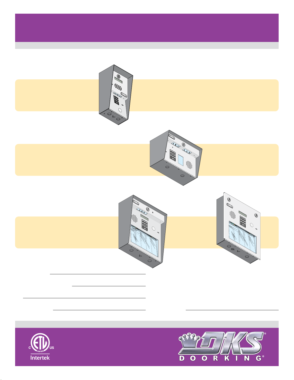
PC Programmable Telephone Entry/Access Control System
1802 1808 1810 Access Plus
1802 1808 1810 Access Plus
Use this manual for circuit board 1970-010 Revision U or higher.
Control a main door, gate and six additional RS-485 entry points.
Surface Mount
1
2
3
1802
1802
Access Plus
1808
1808
Access Plus
1802-092
INS
1
.
L
ocate
D
ir
2.
Press Code Number.
If Li
B
T
3.
E
4
5
6
7
8
9
OP
E
RA
0
T
T
RUC
ING
TIONS
Co
e
c
d
to
e
ry.
N
u
mb
ne
e
utt
r
i
s
o
on
B
n
usy
ry
to
Agai
,
H
P
a
ress
n
ng
te
n
.
r
U
A
on
p
n
.
y
Ton
e
.
Surface Mount
1
2
3
4
5
7
6
NA
ME
A
8
d
ams
B
e
J
r
n
9
a
r
B
d
r
E
o
wn
Da
0
L
v
i
s
Ho
T
dg
e
Miller
s
S
J
S
m
it
h
T
K
h
o
mas
Z
im
W
me
r
R
1808-085
1810-162-A-6-16
C
ODE
1
9
5
2
4
6
8
3
7
1810
1810
Access Plus
Date Installed:
Installer/Company Name:
Phone Number:
Leave Manual with Owner
Surface Mount
1
2
3
4
5
7
6
8
1
2
3
NA
M
E
1810-095
Copyright 2016 DoorKing, Inc. All rights reserved.
9
0
R
es
s
L
eg
ev
i
i
e
n
H
R
u
e
en
o
R
D
1
3
D
2
i
4
x
o
n
D
23
D
o
1
m
i
n
i
c
3
k
D
3
o
2
n
i
ck
P
1
Do
1
7
n
n
er
K
D
on
t
er
F
l
0
l
d
L
i
2
8
n
r
ew
0
1
s
i
3
x
0
A
2
i
2
K
Hi
s B
S
2
6
ch
r
7
d
1
u
L
3
A
4
st
u
2
0
6
8
P
8
8
8
5
1
8
3
5
8
4
6
7
7
6
5
9
5
4
9
9
2
8
ci
9
er
9
d
H
S
S
6
i
i
B
ee
t
ch
18
8
l
M
8
ey
6
7
J
an
3
J
3
c
H
S
i
8
i
n
el
t
ch
i
2
0
l
ec
G
M
3
6
F
2
3
ast
k
4
H
7
H
S
i
6
n
o
h
D
d
a
3
8
er
M
g
3
8
es
3
3
R
as
1
A
0
t
H
S
o
1
o
h
n
o
8
a
5
F
n
M
ver
3
5
k
5
1
o
0
D
zi
H
6
J
S
n
9
en
a
i
m
3
7
J
se
M
0
o
3
n
2
1
n
u
s
2
ce
D
4
L
Jo
S
r
7
m
a
h
0
4
J
i
n
M
t
6
3
h
so
4
5
u
J
1
l
n
i
2
n
Jo
S
M
2
B
o
h
0
m
0
n
N
0
5
a
so
5
ab
5
c
0
h
n
o
4
H
Jo
S
T
r K
0
t
e
n
4
0
e
es
N
9
8
l
e
0
ab
2
A
F
6
u
4
Jo
S
r
0
J
t
o
n
3
65
l
es
N
4
l
ac
1
eu
0
G
h
4
man
4
S
H
7
yn
8
7
n
f
Ni
7
9
o
9
J
1
l
xo
0
A
0
n
T
6
o
R
m
5
0
P
5
2
l
in
7
a
1
t
s
7
t
er
o
4
T
n
5
o
so
L
mp
0
07
n
P
3
2
e
F
6
s
r
o
5
ez
n
4
T
6
o
A
F
mp
4
1
P
1
0
9
e
0
so
t
5
r
o
n
0
T
l
1
yl
l
S
i
er
A
3
R
3
Q
ay
4
3
J
3
W
0
as
2
1
hi
3
n
2
g
1
W
t
1
o
a
n
2
s
G
2
h
9
i
n
5
g
4
W
t
3
o
e
n
0
n
K
0
t
7
L
9
8
W
7
hi
1
t
3
i
n
4
g
3
5
M
W
2
i
n
60
st
9
o
n
F
W
ya
3
8
t
t
9
J
67
9
2
1
1
6
7
0
4
4
1
Circuit Board
Serial Number
and Revision Letter:
Flush Mount
1
2
3
4
5
7
6
8
1
.
Lo
2
3
1810-096
9
O
c
a
t
e
C
o
de
pera
0
ti
n
N
g
u
m
I
b
ns
e
r
t
O
r
n
u
D
c
ir
t
ions
e
c
t
o
ry
Jen
3
se
M
0
2
n
u
7
ce
D
6
Jo
5
r
a
h
0
J
n
Mul
64
so
9
n
5
i
n
Jo
4
M
B
h
0
n
N
05
so
ab
9
n
92
o
Jo
T
r
K
n
4
e
N
9
s
0
ab
A
u
Jo
r
J
n
3
e
N
4
s
1
e
G
u
m
a
n
87
n
Ni
9
J
x
o
n
R
5
P
5
7
at
t
er
so
03
n
P
2
e
F
r
ez
F
4
P
1
9
et
r
o
l
l
i
A
R
ay
J
S
i
m
7
o
3
n
1
s L
2
4
S
7
m
4
i
t
3
h
5
J
1
2
S
2
o
m
0
5
a
5
c
0
h
4
S
H
0
t
e
0
e
8
l
e
2
F
6
4
S
0
t
o
6
l
l
5
ac
0
h
4
4
S
H
7
yn
7
f
9
o
1
l
0
A
0
T
6
o
m
0
2
l
i
n
1
so
7
4
T
n
5
o
L
m
0
7
p
6
so
5
n
4
T
6
o
A
m
1
0
p
0
so
50
n
T
S
1
yl
er
3
3
Q
4
3
3
W
0
as
2
1
h
3
i
n
21
g
W
t
1
o
a
n
2
sh
G
2
9
i
n
5
g
4
W
t
3
o
en
n
0
K
0
t
L
7
9
8
W
7
h
1
i
t
3
i
n
4
g
3
5
M
W
2
i
n
6
st
0
9
o
n
W
F
y
3
at
8
t
9
J
6
7
9
2
1
1
6
7
0
4
4
1
UL Listed
Copyright 2009 DoorKing, Inc. All rights reserved.

QUICK GUIDE: Terminals & LED Descriptions
J1
J1
Phone In
(Twisted Pair)
OR
Wireless
Adapter
Phone Out
(Twisted Pair)
Emergency
and/or Postal
Entry Switch
Back-Up
Battery Power
Relay 1
(Access Control Device)
Relay 2
(Access Control Device)
Input Power
(Transformer)
DO NOT
use 24V.
1. Phone In (Negative - Ring)
18-PIN Terminal
2. Phone In (Positive - Tip)
3. Ground (Required)
4. Phone Out (Positive - Tip)
5. Phone Out (Negative - Ring)
6. Not Used.
7. Switch Input Relay 1. A switch closure across terminals 7 & 9
will activate relay 1 for its programmed strike time.
8. Switch Input Relay 2. A switch closure across terminals 8 & 9
will activate relay 2 for its programmed strike time.
9. - 12 VDC Battery Negative. Also Common for terminals 7 & 8.
10. + 12 VDC Battery Positive.
11. Relay 1 Normally Open
12. Relay 1 Normally Closed
13. Relay 1 Common
14. Relay 2 Normally Open
15. Relay 2 Normally Closed
16. Relay 2 Common
17. 16.5 VAC Input Power
18. 16.5 VAC Input Power
WARNING
Maximum
input voltage to terminals
9 and 10 is 14.5 Volts DC.
BATT CHARGE LED: When
battery is connected to 9
and 10, Green LED will
light when charging and
turn OFF when charged.
Over Voltage Power Note: OV LED will light up if too much power is applied to circuit board.
1970-010
J1
1
2
3
4
5
6
7
8
9
10
11
12
13
14
15
16
17
18
OV
J4
1
2
3
4
5
6
7
8
BATT
CHARGE
1970-010
J1
1
2
3
4
5
6
7
8
9
10
11
12
13
14
15
16
17
18
RS-485 DATA A (+)
RS-485 DATA B (-)
RS-485 Common
Terminals 4-8 are
ONLY used with
1816 Access Plus
Telephone
Interface
application.
See section 1.9.
J4
1
2
3
4
5
6
LAN CONNECTION
CONNECTION
7
8
8-PIN
Terminal
SW2
TERMINATION
BAD DNS
LAN
ON
J1
RJ-45
RJ-45
Jack
Connector
(Cat5)
(Cat5)
RS-485 RX
RS-485 RX
LAN DOWN
LAN DOWN
DATA
DATA TRANSMIT
TRANSMIT
SW1
ON
MODEM / TCP ENB
MODEM / TCP ENB
PHONE LINE
1972-010
Interface Board
J3
KEYPAD
PHONE LINE
IN USE
IN USE
MIC VOL
MASTER
CODE
Microphone
Gain Adjust
Speaker
OV
1970-010
SPEAKER
VOL
J2
1112345678910
Volume
Adjust
RS-485 RX - Green LED indicates that the system is on-line and scanning the RS-485 devices.
BAD DNS - Yellow LED indicates an email server problem, rejecting the mail server.
LAN DOWN - Red LED indicates a problem with the LAN. IP or Gateway (router) down or wrong gateway IP address.
PHONE LINE IN USE - Yellow LED indicates that the phone line is being used (dial-out, call forwarding, etc.).
LAN CONNECTION - Green LED indicates that the wire connection from the unit to the computer or router is good.
DATA TRANSMIT - Yellow LED indicates that the TCP / IP connection is transmitting data or sending an email.
SW1 - Modem/TCP Enable - Turning SW1 Off disables the modem and TCP / IP, but will speed up programming from the keypad.
SW2 - Termination Switch - Only used when RS-485 access control devices are being used (See section 1.11.1).
2 Quick Guide - 1
1810-162-A-6-16

Quick Reference Table
Page # Factory SettingsSection Command
Section 2.1 Programming Master Code
Program a Master Code
2.132
Press Master
Code Button
NO Master Code
Programmed
Section 2.3 Programming Network Setup for a Computer
Enable / Disable TCP / IP Support - System Reboot
Set the Unit’s IP Address (reboot required)
Sub-Net Mask (reboot required)
Set the Gateway (Router) IP Address (reboot required)
NOT Programmable from Software.
Program from System Keypad ONLY.
Set the Port Number (reboot required)
34
34
35
35
35
2.3.1
2.3.2
2.3.3
2.3.4
2.3.5
*
*
*
*
*
5 0
5 1
5 2
5 3
5 6
192.168.001.030
255.255.255.000
192.168.001.001
Section 2.4 System Parameters Programming
Single or Multiple Systems
Single or Double Ring
Number of Resident Rings Before Unit Hangs Up
Talk Time
Relay Strike Time
Tone Open Numbers
Answer Incoming Call on X Rings
Call Waiting ON / OFF
Turn Speaker On / Control Relay from Phone Call
Set Call Forward Microphone Gain & Speaker Volume
Hang-Up Tone
(1816 Interface ONLY)
(1816 Interface ONLY)
(1816 Interface ONLY)
37
37
37
38
38
38
39
39
39
40
40
2.4.2
2.4.4
2.4.5
2.4.6
2.4.7
2.4.8
2.4.9
2.4.11
2.4.12
2.4.13
2.4.14
*
*
*
*
*
*
*
*
*
*
*
6 1
6 3
6 4
0 8
0 3
0 5
1 8
2 0
1 6
1 1
1 7
1 (Single System)
1 (Double Ring)
05 (5 Rings)
060 (60 Sec.)
Relay 1: 9 8 7 6
Relay 2: 5 4 3 2
Relays 3-8 Not Set
06 (6 Rings)
7 (Mic) 1 (Speaker)
Section 2.5 Directory Codes
Directory Codes 1 – 23 Pre-Set (1816 Interface ONLY)
Directory Codes 24 – 50 “Dial Phone Number”
Delete a Phone Number from Directory Codes 24 – 50
Delete All Phone Numbers from Directory Codes 24 – 50
40
40
41
41
2.5.0
2.5.1
2.5.2
2.5.3
*
*
*
*
4 0
4 1
4 2
4 3
Section 2.6 Access Codes for Access Control Devices
“Simple” Access Code Programming (Relays 1&2: 24/7 Operation)
Number of RS-485 Devices
Additional Relay Off-Line Function
“Time Zone Restricted” Device Access Code Programming
Delete an Access Code (Simple or Time Zone Restricted)
Delete All Access Codes for the Same Type of Device (Simple or TZR)
Program Temporary Access Codes
Delete Temporary Access Code
Delete All 10 Temporary Access Codes
(Up to 10)
41
41
42
42
42
42
43
43
43
2.6.1
2.6.2
2.6.3
2.6.4
2.6.5
2.6.6
2.6.7
2.6.8
2.6.9
*
*
*
*
*
*
*
*
*
0 2
0 9
0 7
7 0
7 1
7 2
7 3
7 4
7 5
Section 2.7 Time Functions
Time and Date Calendar Chip Programming
Automatic Relay Activation Time Zone Programming (Up to 4 zones)
Access Code Time Zone Programming (Up to 4 zones)
44
44
45
2.7.1
2.7.5
2.7.6
*
*
*
3 3
3 5
3 6
Section 2.8 Miscellaneous
Restore Factory Settings
Erase Transaction Log
Note: Program section numbers have been intentionally skipped that DO NOT apply to these Access Plus systems in this manual. This allows ALL of the
Access Plus manuals to remain in sync with each other when referencing programming numbers.
45
45
2.8.1
2.8.2
*
*
9 0
9 1
0
01030
1 Sec
1 (ON)
N / A
0
Empty
Empty
N/ A
N / A
Empty
0
0
Empty
N / A
N / A
Empty
N / A
N / A
Empty
Empty
Empty
N / A
N / A
1810-162-A-6-16
Quick Guide - 2
3
SPECIFICATIONS
7
8
9
4
5
6
1
2
3
0
P
us
h
B
utton
T
o Cal
l
7
8
9
4
5
6
1
2
3
0
rn
ard
E
lli
n
g
s
L
ro
ke
r
T
B
ro
s
e S
B
ro
w
n
J
B
ro
w
n
K
B
r
ya
n
t
W
Byr
o
n
R
B
ya
n
G
2
2
1
3
2
1
2
4
9
4
7
6
0
0
3
1
1
2
2
9
2
8
2
2
4
9
1
3
2
4
2
3
1
3
3
2
1
1
7
C
o
lyer
R
C
o
rd
u
l
a
D
C
o
u
r
t
E
C
r
ains
G
D
al
to
n
B
D
an
ie
ls
R
D
a
w
ls
J
D
eL
ah
ae
M
D
i
ll
P
D
illo
n
M
D
i
x
o
n
D
D
o
m
in
i
ck
P
D
o
n
ick
P
D
o
n
n
er
K
D
o
n
ter
F
5
0
3
5
0
1
4
0
4
4
6
1
2
4
9
7
7
2
6
3
3
4
8
1
1
0
4
3
2
2
0
6
8
8
8
8
5
1
8
3
5
8
4
6
7
7
6
5
9
5
4
9
9
2
Fara
g
o
F
Farro
w
M
Fern
an
d
e
z
S
G
ar
f
ie
l
d
S
G
ar
r
ea
u
J
G
en
t
r
y
M
G
o
n
z
alez
H
H
ab
er
f
el
d
A
H
a
m
m
er
V
H
en
d
rix
K
H
ir
d
A
H
it
c
h
J
H
it
ch
F
H
o
d
g
es A
H
o
o
ve
r
H
Je
n
s
en
D
Jo
h
n
s
o
n
M
J
o
h
n
so
n
T
Jo
n
es
A
Jo
n
es
G
3
5
2
W
h
i
t
in
g
M
W
in
sto
n
F
W
y
at
t
J
1
3
4
6
0
9
3
8
9
6
7
9
2
1
1
6
7
0
4
4
1
7
8
9
4
5
6
1
2
3
0
7
8
9
4
5
6
1
2
3
0
c
a
t
e
C
o
de
N
u
m
b
e
r
O
n
D
i
r
ec
t
o
r
y
e
s
s
C
od
e
N
u
m
b
er.
I
f
L
in
e
I
s
Bu
s
y,
P
r
e
s
s
A
n
y
B
u
t
t
o
n
H
a
n
g
U
p
.
Tr
y
Ag
a
i
n
.
n
t
e
r
O
n
“O
P
EN
” D
i
s
p
l
a
y
o
r
T
o
n
e
.
J
M
e
J
so
n
H
g
a
t
e
B
l
l
i
n
gs
L
r
o
ke
r
T
B
r
o
se
S
B
r
o
w
n
J
B
r
o
w
n
K
B
r
y
an
t
W
B
y
r
o
n
R
B
y
an
G
2
4
9
47
6
0
0
3
11
2
2
9
2
8
2
2
4
9
1
3
2
4
23
1
3
3
2
11
7
C
o
u
r
t
E
C
r
ai
n
s
G
D
a
l
t
o
n
B
D
a
n
i
el
s
R
D
a
w
l
s
J
D
e
L
ah
ae
M
D
i
l
l
P
D
i
l
l
o
n
M
D
i
xo
n
D
D
o
m
i
n
i
ck
P
D
on
i
ck
P
D
o
n
n
e
r
K
D
on
t
e
r
F
5
0
1
4
0
4
4
61
2
4
9
7
7
2
6
33
4
8
1
1
0
4
3
2
2
0
68
8
8
8
5
18
3
5
8
4
6
7
7
6
5
9
5
4
9
9
2
Far
r
o
w
M
F
er
n
an
d
e
z
S
G
a
r
f
i
el
d
S
G
ar
r
ea
u
J
G
e
n
t
r
y
M
G
o
nz
al
ez
H
H
ab
e
r
f
el
d
A
H
a
m
m
er
V
H
e
nd
r
i
x
K
Hi
r
d
A
Hi
t
ch
J
H
i
t
ch
F
H
o
d
g
es
A
H
o
o
v
er
H
J
en
sen
D
J
o
h
n
so
n
M
J
o
h
n
so
n
T
J
o
nes
A
J
o
n
es
G
82
8
3
4
2
7
3
3
4
4
1
6
1
2
9
1
4
54
2
1
2
0
7
3
2
1
8
6
2
3
2
3338
3
5
30
2
0
6
4
0
0
5
49
0
3
4
1
8795
57
0
3
2
4
19
Jo
r
g
en
sen
B
K
l
ei
n
D
K
no
b
l
i
c
h
B
L
am
b
B
L
an
d
D
L
a
n
der
s
S
L
a
n
g
s
t
r
o
m
B
L
e
vi
n
e
D
L
e
w
i
s
B
L
u
ci
d
i
B
M
a
n
ci
n
i
G
6
79
2
1
1
6
70
4
4
1
J1
1
2
3
4
5
6
7
8
9
10
11
12
13
14
1
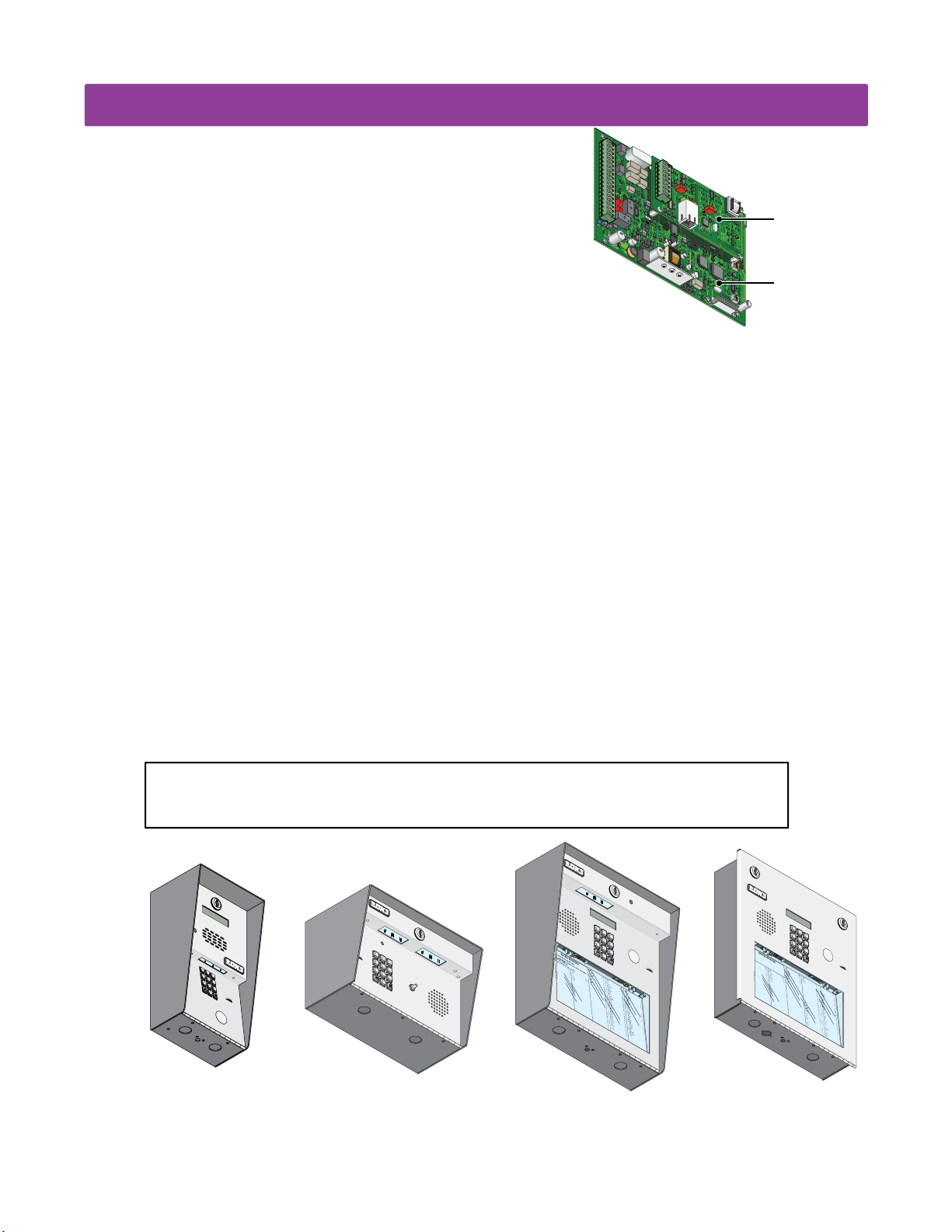
For 1802/1808/1810 Access Plus with circuit board
1970-010 Rev U or higher ONLY.
5
16
17
18
OV
Both Boards Together - 1970-010
Features
• IP Addressable – program from your PC using the DoorKing programming software via a LAN or WAN connection, or via a
built-in modem.
• When internet connection is provided, system can send e-mail notification on 58 selectable events and 20 access codes.
• Two internal relays allow the system to control a main entry gate plus a pedestrian access gate.
• Control up to six (6) additional entry points with card readers, keypads or wireless RF via RS-485 connection.
• 100 card / transmitter / keypad codes when programming from the software application.
• Holiday schedule.
• 500 event transaction buffer.
• Unique distinctive ring (when interfaced with the 1816 Access Plus telephone interface).
• Unit connects directly to the tenant’s existing telephone line. No additional monthly expense for a second telephone line (when
interfaced with the 1816 Access Plus telephone interface).
• Built in call waiting assures that incoming calls or guest calls are not missed (when interfaced with the 1816 Access Plus
telephone interface).
• Up to 27 preprogrammed dial-out telephone numbers + 23 pre-set phone interface lines (when using the 1816 Access
Plus telephone interface).
• Built-in clock / calendar.
• Four hold-open time zones.
• Entry code time zones.
• 10 temporary access codes.
• Unit can be programmed to work with PBX and KSU phone systems.
• Optional secondary keypad can be added for remote entry code activation of door or gate. Order part number 1812-082.
J4
1
2
3
4
5
ON
6
SW
2
7
RS-485
8
RX
BAD
DNS
J1
LA
N
DOW
RJ-45
N
SW
ON
Jack
1
(Cat5)
MODE
M
19
72-010
J3
KEYPAD
1970-010
J2
1
2
3
45
6
7
8910
MASTER
CODE
MIC VO
L
SPEAKE
R
VO
L
11
Interface Board
Control Board
Included with the system is an extra random keyed cabinet lock. If desired, for added security against
unauthorized entry into the system, the standard lock may be replaced with the random lock.
Note: DoorKing cannot replace this specific lock or keys if lost.
1
.
L
o
c
2
a
.
t
e
P
C
r
o
e
de
s
s
t
N
o
C
u
od
H
m
3
a
e
.
n
b
N
g
e
E
r
-
u
n
U
O
m
t
p
e
n
b
r
.
er.
D
N
Tr
O
A
i
n
y
M
r
ec
I
“O
E
f
Ag
L
t
o
A
P
in
a
d
r
EN
i
am
y
e
n
.
s
I
” D
s
J
A
Bu
k
i
i
n
s
s
s
p
M
y,
l
a
A
y
P
n
n
r
o
ese
e
r
s
T
J
s
A
o
n
A
d
n
er
n
e
so
.
n
A
p
H
p
l
e
g
a
t
e
B
B
i
l
l
i
C
n
gs
o
u
r
L
t
B
E
r
o
2
ke
C
4
r
9
r
ai
T
n
B
s
r
G
o
47
se
D
a
6
l
S
t
o
B
n
r
B
o
0
w
D
0
a
n
3
n
J
i
el
B
s
r
o
11
R
w
D
a
n
2
w
K
l
s
B
r
J
y
2
an
D
9
e
2
t
L
W
ah
B
ae
y
r
8
o
D
2
M
n
i
2
l
l
R
P
B
y
an
4
D
9
G
i
1
l
l
o
n
M
3
D
2
i
4
xo
n
D
23
D
o
1
m
i
n
i
ck
3
D
3
P
on
2
i
ck
P
11
D
o
7
n
n
e
r
K
D
on
t
e
r
F
1810
Flush
1
4
7
y
B
u
t
t
o
n
Far
r
o
w
5
M
0
F
1
er
n
an
4
d
0
e
G
4
z
a
S
r
f
i
el
d
4
61
S
G
ar
r
ea
2
u
4
J
G
9
e
n
t
r
y
7
M
7
G
2
o
nz
al
6
ez
33
H
H
ab
e
r
f
4
el
8
d
H
1
a
A
m
m
er
1
0
H
4
V
e
nd
r
i
x
3
2
K
Hi
2
r
d
A
0
68
Hi
t
ch
J
8
8
H
8
i
t
ch
F
5
18
H
o
d
g
es
3
5
A
H
8
o
o
v
er
4
H
6
J
7
en
sen
7
D
6
J
5
o
h
n
so
9
n
5
J
4
M
o
h
n
so
9
n
9
J
2
T
o
nes
A
J
o
n
es
G
2
3
5
6
8
9
0
Jo
r
g
en
sen
82
K
8
l
ei
B
n
D
3
K
4
2
no
b
l
i
c
7
h
L
3
B
am
3
b
B
4
L
4
an
1
d
D
6
L
1
a
2
n
der
s
9
L
S
1
a
4
n
g
s
t
r
54
o
L
m
e
2
vi
B
n
e
D
1
L
2
e
0
w
i
s
B
7
L
3
u
2
ci
d
i
B
1
M
8
6
a
n
ci
n
i
2
G
3
2
33
3
8
3
5
30
2
0
6
4
0
0
5
49
0
3
4
1
87
9
5
57
0
3
2
4
19
6
79
2
1
1
6
70
4
4
1
1810-162-A-6-16
1
2
3
4
5
7
6
1
1
2
3
4
1
2
3
4
5
6
7
8
9
OPERATING
INSTRUCTIONS
0
1
.
Lo
cate
Di
r
2.
Co
ector
Press Code
de
y
Num
.
If
L
i
n
ber on
e
B
u
i
Number
s
t
t
o
B
n t
Tr
u
s
y
o
y
3
,
A
Ha
.
P
.
gain
En
r
e
ng
te
ss
.
r
Up
A
o
n
n
.
y
T
one.
1802
5
7
8
0
1808
6
Push B
9
utt
T
o Call
on
2
3
N
A
M
E
B
ern
B
illin
B
B
B
1810
8
9
0
C
o
lyer
Fara
R
2
C
g
2
ard
o
o
1
rd
5
F
0
u
Farro
E
3
l
a
3
D
C
2
g
o
w
1
s
u
5
M
r
0
L
t
Fern
1
E
ro
2
ke
C
4
an
r
9
r
ains
4
d
T
0
e
G
z
4
ro
ar
G
S
4
f
s
D
ie
7
e S
al
6
l
d
4
to
6
S
G
n
1
ro
ar
B
0
r
w
D
0
ea
an
n
3
u
2
J
ie
4
J
G
B
9
ls
ro
en
1
R
w
D
t
1
r
a
n
y
2
w
7
K
M
7
ls
G
B
2
r
o
J
ya
n
2
D
z
9
n
alez
eL
2
t
6
W
ah
3
H
Byr
3
H
ae
ab
8
o
D
M
er
2
n
i
2
ll
f
4
R
el
P
8
d
H
B
1
ya
a
A
m
4
D
n
9
m
illo
1
G
1
er
0
n
H
4
V
M
en
3
D
d
2
rix
i
4
x
3
o
2
n
K
H
2
D
ir
d
2
D
3
A
o
1
m
0
6
in
H
8
it
i
ck
c
3
D
h
3
P
o
2
J
n
8
ick
8
H
8
it
P
ch
1
D
1
o
7
F
n
5
n
1
H
er
8
o
d
K
D
g
o
es A
n
3
ter
5
H
8
o
F
o
ve
r
4
H
6
Je
7
n
s
en
7
D
6
Jo
5
h
n
s
o
9
n
5
J
M
4
o
h
n
so
9
n
9
Jo
2
T
n
es
A
Jo
n
es
G
W
h
1
i
t
3
in
4
g
3
5
M
W
2
in
6
sto
0
9
n
W
F
y
3
at
8
t
9
J
6
7
9
2
1
1
6
7
0
4
4
1
Surface
DoorKing, Inc. reserves the right to make changes in the products described in this manual without notice and without obligation of DoorKing, Inc. to notify any persons of any such
revisions or changes. Additionally, DoorKing, Inc. makes no representations or warranties with respect to this manual. This manual is copyrighted, all rights reserved. No portion of this
manual may be copied, reproduced, translated, or reduced to any electronic medium without prior written consent from DoorKing, Inc.
4

TABLE OF CONTENTS
Quick Guide: Terminals and LED Descriptions
Quick Reference Table
SPECIFICATIONS
Important Notices FCC - United States, DOC - Canada
General Information Installation Guidelines and Safety Information
SECTION 1 - INSTALLATION
1.1 Mount the Access Plus System
1.1.1 1802 Access Plus
1.1.2 1808 Access Plus
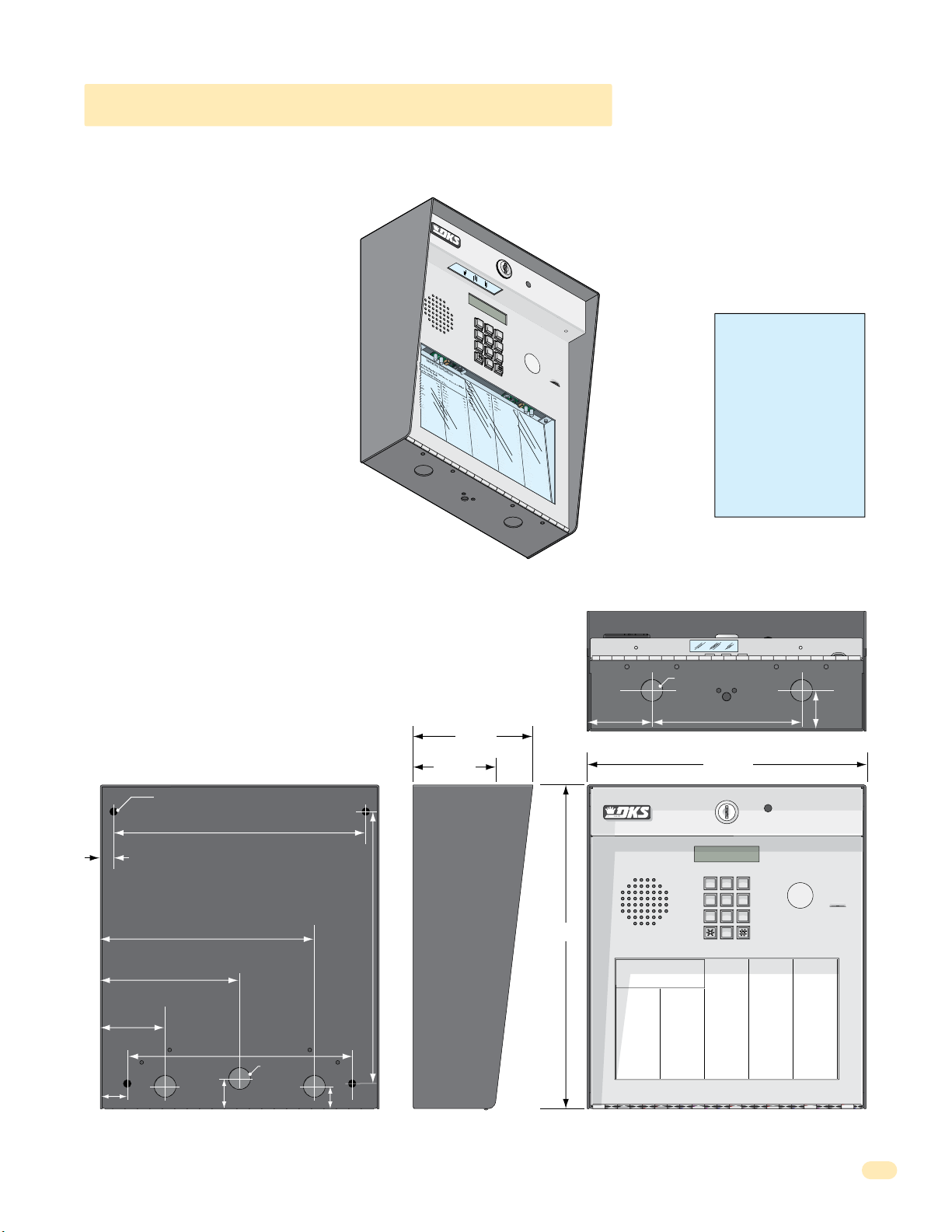
1.1.3 1810 Access Plus Surface Mount
1.1.4 1810 Access Plus Flush Mount
1.2 Postal Lock Installation
1.3 Telephone Line Wire
1.4 16.5 VAC Power Wiring ONLY!
1.5 Grounding and Surge Suppression
1.6 Wire ONE Unit to a Telco Line - Auto-Dialer
1.7 Wire ONE Unit to the Internet - Auto-Dialer
1.8 Wire Multiple Units - Auto-Dialer: Telco/Internet
1.9 1816 Access Plus Telephone Interface Wiring
1.10 Main Terminal Description
1.11 Access Plus System Interface Board
1.11.1 RS-485 8-Pin Connector Description
RS-485 Daisy Chain Wiring
RS-485 Configurations, Sample of Multiple Unit Configuration Connection (Auto-Dialer ONLY)
1.11.2 Network Connections
1.11.3 Phone Modem Connection
Quick Guide - 1
Quick Guide - 2
Previous Page
3
4
5
5
6
7-8
9-11
12-15
16
17
18
18
19
20
21
22-23
24
24
25
26
27
28-29
30
SECTION 2 - PROGRAMMING
2.1 Programming the Master Code
2.2 Programming Methods
2.3 Programming the Network Setup for a Computer
2.3.1 Enable / Disable TCP / IP Support - System Reboot
2.3.2 Set the Access Plus System IP Address (reboot required)
2.3.3 Sub-Net Mask (reboot required)
2.3.4 Set the Gateway (Router) IP Address (reboot required)
2.3.5 Set the Port Number (reboot required)
2.4 System Parameters Programming
Programming from the System Keypad
Programming from a Touch-Tone Telephone
Quick Reference Table
2.4.2 Single or Multiple Systems
2.4.4 Single or Double Ring
2.4.5 Number of Resident Phone Rings Before Unit Hangs Up
2.4.6 Talk Time
2.4.7 Relay Strike Time
2.4.8 Tone Open Numbers
2.4.9 Answer Incoming Call on X Rings
2.4.11 Call Waiting ON/OFF
2.4.12 Turn Speaker On / Control Relay from Phone Call
2.4.13 Set Call Forward Microphone Gain and Speaker Volume
2.4.14 Hang-Up Tone Number
31
31
32
33
33
33
34
34
34
35
35
35
36
37
37
37
38
38
38
39
39
39
40
40
1810-162-A-6-16
1

TABLE OF CONTENTS
2.5 Directory Codes
2.5.0 Directory Codes 01 – 23 PRE-SET (1816 Access Plus Telephone Interface ONLY)
2.5.1 Directory Codes 24 – 50 Programming “Dial Phone Number”
2.5.2 Delete a Phone Number from Directory Codes 24 – 50
2.5.3 Delete ALL Phone Numbers from Directory Codes 24 – 50
2.6 Access Codes to Operate Access Control Devices
2.6.1 “Simple” Access Code Programming (Relays 1&2: 24/7 Operation)
2.6.2 Number of RS-485 Devices
2.6.3 Additional Off-Line Relay Function
2.6.4 “Time Zone Restricted” Access Code Programming
2.6.5 Delete an Access Code (Simple and Time Zone Restricted)
2.6.6 Delete All Access Codes for the Same Type of Device (Simple and Time Zone Restricted)
2.6.7 Temporary Device Access Code Programming
2.6.8 Delete a Temporary Device Access Code
2.6.9 Delete ALL Temporary Device Access Codes
2.7 Time Functions
2.7.1 Time and Date Calendar Chip Programming
2.7.5 Automatic Relay Activation Time Zone Programming (Up to 4)
2.7.6 Access Code Time Zone Programming (Up to 4)
2.8 Miscellaneous
2.8.1 Restore Factory Settings
2.8.2 Erase Transaction Log
SECTION 3 - ADJUSTMENTS
Speaker Volume
Microphone Gain
Interface Board LED Status
System Keypad
40
40
40
41
41
41
41
41
42
42
42
42
43
43
43
44
44
44
45
45
45
45
46
46
46
46
46
SECTION 4 - USER INSTRUCTIONS
4.1 Resident Operating Instructions
4.1.1 Granting or Denying a Guest Access
4.1.2 Call Waiting (1816 Access Plus Telephone Interface ONLY)
4.1.3 Dial-Out Phone Numbers
4.1.4 Access Codes
4.2 Remote Operation
4.2.1 Remote Programming (Touch-Tone Phone)
4.2.2 Remote Relay Activation (Touch-Tone Phone)
4.2.4 Remote Relay Activation Check (Touch-Tone Phone)
SECTION 5 - MAINTENANCE
5.1 Troubleshooting
5.2 Phone Line Polarity
5.3 Troubleshooting Table
5.4 Access Plus Wiring Schematic
5.5 Accessories
5.6 Programmed Information Log Sheets
Master Code, Relays, Access Codes and Time Zone Log Sheets; Directory Code / Dial-Out Phone Numbers Log Sheet;
Access Code Log Sheets (50 with phone numbers, 50 as access only), 1-10 Temporary Access Codes Log Sheet when using
software ONLY.
47
47
47
47
47
47
48
48
48
48
49
49
50
51
52
53
54-61
2
1810-162-A-6-16

Important Notices
FCC – United States
This equipment has been tested and found to comply with the limits for a class A digital device, pursuant to Part 15 of the FCC
Rules and Regulations. These limits are designed to provide reasonable protection against harmful interference when the
equipment is operated in a commercial environment. This equipment generates, uses, and can radiate radio frequency energy
and, if not installed and used in accordance with the instruction manual, may cause harmful interference to radio communications. Operation of this equipment in a residential area is likely to cause harmful interference in which case the user will be
required to correct the interference at his own expense.
FCC Registration Number: DUF6VT-12874-OT-T
DOC - Canada
The Canadian Department of Communications label identifies certified equipment. This certification means that the equipment
meets certain telecommunications network protective, operational, and safety requirements. The Department does not guarantee the equipment will operate to the users satisfaction.
Before installing this equipment, users should ensure that it is permissible to be connected to the facilities of the local telecommunications company. The equipment must also be installed using an acceptable means of connection. The customer should be
aware that compliance with the above conditions may not prevent degradation of service in some situations.
Repairs to certified equipment should be made by an authorized Canadian maintenance facility designated by the supplier. Any
repairs or alterations made by the user to this equipment, or equipment malfunctions, may give the telecommunications
company cause to request the user to disconnect the equipment.
Users should ensure, for their own protection, that the electrical ground connections of the power utility, telephone lines, and
internal metallic water pipe system, if present, are connected together. This precaution may be particularly important in rural
areas.
CAUTION: Users should not attempt to make such connections themselves, but should contact the appropriate electric inspection authority, or electrician, as appropriate.
DOC Registration Number: 1736 4507 A
Notice:
The Load Number (LN) assigned to each terminal device denotes the percentage of the total load to be connected to a telephone
loop which is used by the device, to prevent overloading. The termination on a loop may consist of any combination of devices
subject only to the requirement that the sum of the load numbers of all the devices does not exceed 100.
Notice:
DoorKing does not provide a power transformer on units sold into Canada. Use only transformers that are CSA listed to power
the telephone entry system. The Access Plus system requires a 16.5-volt, 20 VA transformer.
1810-162-A-6-16
3

General Information
• Prior to beginning the installation of the telephone entry system, we suggest that you become familiar with the
instructions, illustrations, and wiring guidelines in this manual. This will help insure that you installation is performed in
an efficient and professional manner.
• The proper installation of the telephone entry panel is an extremely important and integral part of the overall access
control system. Check all local building ordinances and building codes prior to installing this system. Be sure your
installation is in compliance with local codes.
• When used to control a door or pedestrian gate, try to locate the telephone entry system as near as possible to the entry
point. The unit should be mounted on a rigid wall to prevent excessive shock and vibration from closing doors or gates.
Continuous vibration and shock from slamming doors or spring-loaded pedestrian gates will damage the circuit board.
Under no circumstances should the unit be mounted directly to a moving door or gate.
• ADA mounting requirements for door control. The requirements below apply only when the telephone entry system is
being used to control entry through a public door only. If this system is used to control entry through a vehicular gate or
private entrance, the dimensions noted below do not apply.
1. If the clear floor space allows only forward approach to the system, the maximum high forward reach allowed is
48 inches above grade to the top of the keypad.
2. If the high forward reach to the system is over an obstruction of greater than 20 inches but less than 25 inches,
the maximum high forward reach allowed is 44 inches above grade to the top of the keypad.
3. If the clear floor space allows parallel approach by a person in a wheelchair, the maximum high side reach shall
be 54 inches above grade to the top of the keypad.
4. If the high side reach is over an obstruction of 24 inches or less, the maximum high side reach allowed is 46
inches above grade to the top of the keypad.
• When used to control a vehicular gate with an automatic gate operator, the telephone entry system must be
mounted a minimum of ten (10) feet away from the gate and gate operator, or in such a way that a person cannot
operate the entry system and/or touch the gate or gate operator at the same time.
• Be sure that the system is installed so that it is not directly in the traffic lane. Goose neck mounting post and kiosks
work well for these type systems. When planning where to locate the system, take into consideration traffic lane layouts,
turn around lanes for rejected access, conduit runs, power availability, etc.
• Environmental factors must also be taken into account. Surface mount units are designed for direct outdoor
installations, however it is preferable to protect them from direct exposure to driven rain or snow whenever possible.
Flush mount units must be protected from direct exposure to the elements.
• This telephone entry system contains a number of static sensitive components that can be damaged or destroyed by
static discharges during installation or use. Discharge any static prior to removing the circuit board from the lobby panel
by touching a proper ground device.
• Instruct the end user to read and follow these instructions. Instruct the end user to never let children play with or
operate any access control device. This Owner’s Manual is the property of the end user and must be left with them
when installation is complete.
4
1810-162-A-6-16

SECTION 1 - INSTALLATION
Installation of the Access Plus Telephone Entry System involves the installation of the hardware and the wiring of these components. Be sure that all dirt, metal or wood debris is removed from inside after mounting it. Any debris inside could damage the
control board and cause the Access Plus system to malfunction during operation.
When the Access Plus system is used to control a vehicular gate with an automatic gate operator, it must be
mounted a minimum of ten (10) feet away from the gate and gate operator, or in such a way that a person
cannot operate the Access Plus system and/or touch the gate or gate operator at the same time.
WARNING
Included with the system is an extra random keyed cabinet lock. If desired, for added security against unauthorized entry into the system,
the standard lock may be replaced with the random lock. Note: DoorKing cannot replace this specific lock or keys if lost.
1.1 Mount the Access Plus System
Ground
Wire
18-PIN
1810
Surface
Mount
Enclosure
J1
1
2
3
4
5
6
7
8
9
10
11
12
13
14
15
16
17
18
OV
Terminal
J4
1
2
3
4
5
6
SW
ON
2
7
RS
-
8
4
85
RX
BAD
DNS
J1
LA
N
DO
W
N
RJ-
45
S
ON
W1
Jack
(Cat5)
M
ODE
M
M
A
S
TE
R
C
ODE
197
KEYP
AD
Door
2-01
0
Accessorie
Plug
M
IC
VO
L
1970-01
SP
0
E
J
AK
2
E
R
VOL
12
345
6
7
891
0
1
1
s
Keypad
Plug
Remove the Control
Board and Faceplate
The control board removal is the same
for all access plus systems.
CAUTION The control board contains
static sensitive components. Discharge
any static electricity from your hands
by touching a proper ground device
before removing the control board.
1810-162-A-6-16
Faceplate
Hing
e
Locknuts
Faceplate
Mfg.
in U.
S.
DO
A.
O
Ac
R
c
K
es
Thi
I
s
N
Control
s
pr
G
or more of
®
oduc
,
S
ince
I
N
S
t is manuf
C
olut
1948
P
.
atent
the foll
i
ons
N
ac
o.
ow
tured under on
ing
Da
te
U
.
S
.
P
atents
e
P
atent
.
No
.
Date
OTHER
PA
DOO
TE
NTS
RK
I
P
NG IN
ENDIN
C., IN
G
G
LEWOOD C
A
D
O
O
P
R
A
R
KI
T
NU
N
M
G
®
B
E
,
R
M
I
N
A
D
C
E
I
.
N
U
SA
R
E
V
SE
R
IA
L
N
O
.
1. Unlock and open the door.
2. Disconnect the keypad plug and
door accessories plug from the
control board.
3. Remove green ground wire.
4. Remove 18-PIN terminal from circuit
board. Not necessary for 1808.
ACCESS CON
S
YSTE
M
T
O
C
R
UT
O
U
O
N
DOOR
D
NI
L
FOR
O
O
T
R
S
K
In
M
U
IN
SE
g
S
l
G
e
/ W
w
TO
M
o
o
o
E
del
U
d
T
,
S
L
C
e
#
a
S
ri
1
a
9
T
8
l
C
0
D
00
#
3
ompl
0
2
S
1
94
er
F
.
i
C
e
i
e
s
.C
s
F
.
D
.C
Reg
U
.
C
F
.
6
i
R
s
P
V
tr
a
i
T
ng
rt
-1
ation
e
2
6
J
r
874
8
a
E
c
#
quiv
k
-
USOC R
OT
.
-T
0
.
0
A
J11C
or
W
5. Remove the 4 screws from board.
Carefully remove control board.
Keep the control board in a protected
area during the mounting installation.
6. Remove faceplate from the housing.
7. Mount enclosure, see following
pages for specific mounting of your
chosen access plus system.
5
9
6
3
0
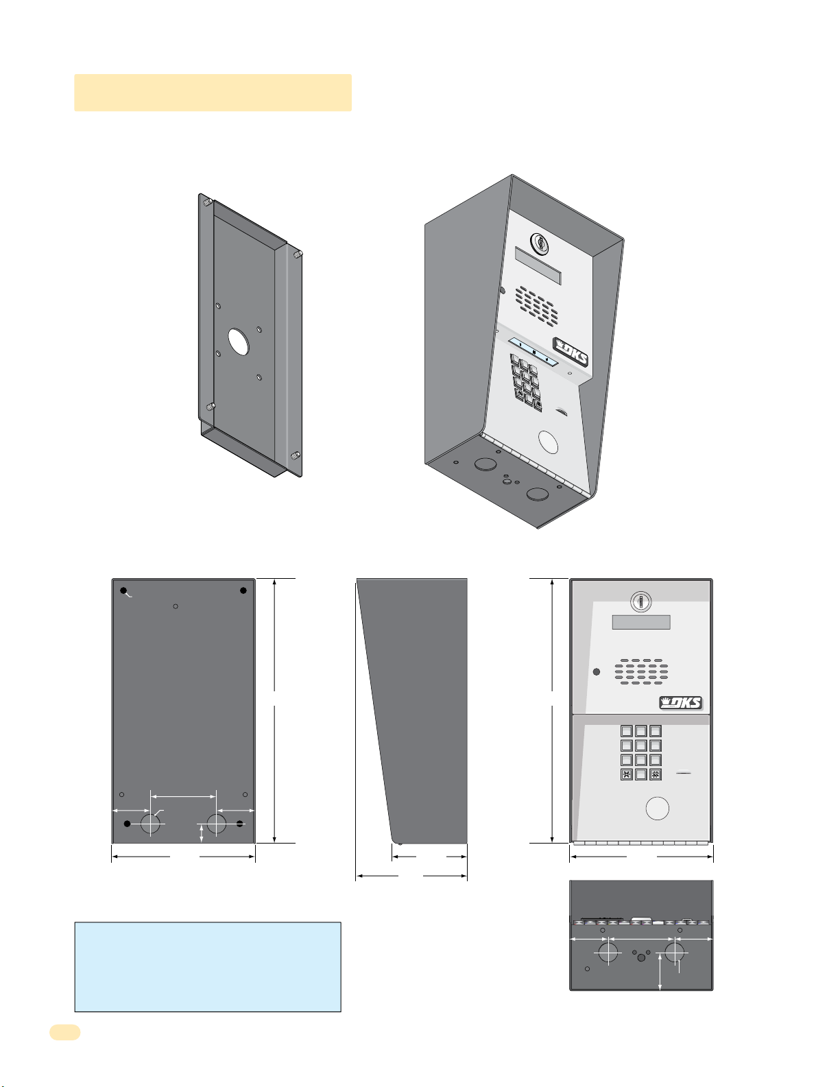
1.1.1 1802 Access Plus
7
8
9
4
5
6
1
2
3
0
Surface mount units can be mounted directly to a wall, pilaster, post mounted using a DoorKing Adapter Plate (P/N 1802-111)
with DoorKing mounting posts (P/N 1200-036, 1200-045, 1200-0046 and 1200-049). See next page. Be sure the unit is
mounted securely and is not subject to vibration from closing doors or gates.
Adapter
Plate
1
2
3
4
5
6
Sold
Separately
OPERATING
INSTRUCTIONS
1.
Locate Code
D
irecto
2.
Press Code Numb
If
Line is Busy
Button to
Tr
y Again
3.
Enter on To
7
8
9
0
ry.
N
u
m
ber
on
er.
, Pr
Hang
ess
.
U
Any
p
.
ne
.
.25” Dia. Mounting Hole
12” 12”
3”
1.75”
.875” Dia
.875”
1.75”
6.5”
WARNING! If this entry system is used to control a
vehicular gate with an automatic gate operator, the entry
system must be mounted a minimum of ten (10) feet away
from the gate and gate operator, or in such a way that a
person cannot operate the entry system and touch the gate
or gate operator at the same time.
Side ViewBack View Front View
11223
44556
77889
0
6.5”
3.375”
1.
2.
3.
OPERATING
INSTRUCTIONS
Locate Code Number on
Directory.
Press Code Number.
If Line is Busy, Press Any
Button to Hang Up.
Try Again.
Enter on Tone.
5”
1.625”
.875” Dia
Bottom View
1.75”1.75” 3”
6
1810-162-A-6-16

1.1.1 1802 Access Plus Continued
The illustrations below show typical installations but specific installations can vary from this.
1. Mount the enclosure using the mounting holes provided in the corners (see sections 1.2 and 1.3 for your chosen model
dimensions). Be sure that mounting screws or nuts (Not supplied) do not protrude into the enclosure where they could cause a
short on the back of the circuit board. Make any necessary conduit connections through the back or bottom of the enclosure
using the existing conduit knock-outs. DO NOT make any new conduit holes in the enclosure.
2. Route all wiring through conduit or mounting post (not supplied) into enclosure.
3. Clean out the enclosure. Make sure that all dirt, metal and/or wood debris is removed.
4. Re-install components back into the enclosure (Reverse section 1.1). Use the wiring schematics in the back of this manual to
help re-install the components if necessary. DO NOT apply any power at this time.
Mount to a Mounting Post
There are different styles
of DoorKing mounting
posts. All mounting posts
need the adapter plate to
mount the 1802.
P/N 1802-111
Adapter
Plate
Sur
face
Mount
Enclosure
Use hardware supplied with
mounting post to secure
adapter plate to post.
Use hardware supplied with
adapter plate to secure
enclosure to adapter plate.
Note: A gooseneck
mounting post anchored
in concrete does not
make a good ground.
Knock-ou
ts
Mount ON a Surface
(See section 1.2).
Wall
Use appropriate
hardware to secure
enclosure to the wall
(not supplied).
Conduit run
to junction box
Conduit
sweep run
M
ou
nting
S.
.
U
in
I
Mfg.
K
R
C
OO
ess
D
c
c
A
u
d
o
r
p
s
ore
i
h
m
T
r
o
ten
Pa
Surface
Mount
Enclosure
S
crew
s
(Not
supplied)
.
A
.
e
C
s
on
N
.
s
I
r
on
t
i
n
e
,
de
®
t
ut
e
l
n
a
at
G
D
So
P
N
l
S.
o.
ro
ured u
t
.
t
N
1948
c
U
t
on
n
e
ng
nce
at
Si
anufa
P
owi
l
m
l
s
o
i
f
t
e
c
h
t
f
o
e
t
Da
G
N
I
A
o.
C
N
ND
t
E
P
OOD
NTS
EW
E
L
T
G
A
N
P
I
ER
NC.,
I
TH
O
G
N
I
K
R
O
O
D
Jack USOC RJ11C or W
Ringer Equiv. 0.0A
DUF6VT-12874-OT-T
F.C.C. Registration #
Complies F.C.C. Part 68
Serial #
Model # 1800 Series
Inglewood, Ca 90301
DOORKING
OUTDOOR USE / WET
SYSTEM UNITS
ACCESS CONTROL
CONFORMS TO UL STD 294
Knock-ou
ts
1810-162-A-6-16
Run all wires
inside post.
Examples of conduit runs that may be used, depending on how
you choose to run the wiring. Some installations will allow the
conduit to be run outside the wall and connect to the bottom of the
enclosure but this is generally NOT recommended.
7
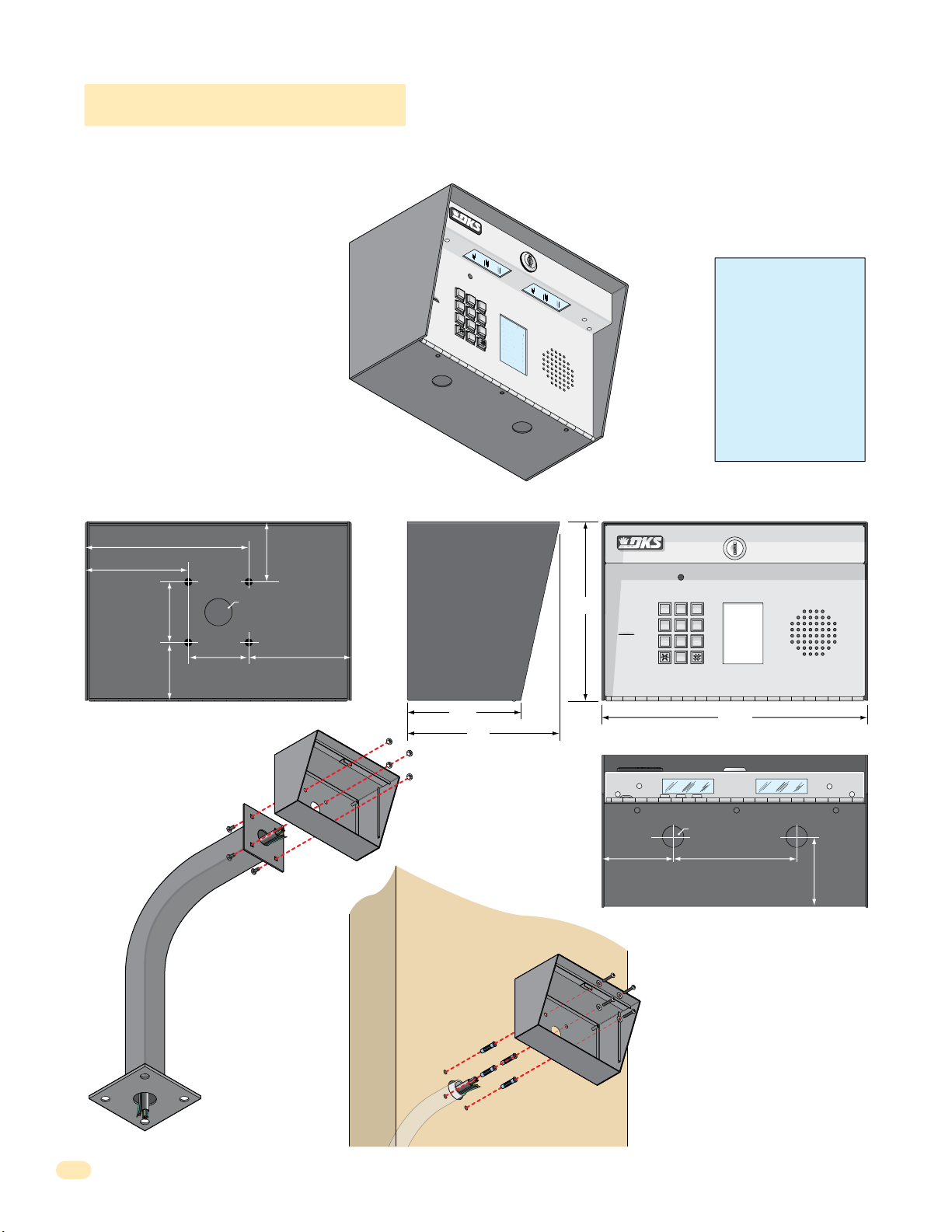
1.1.2 1808 Access Plus
7
8
9
4
5
6
1
2
3
0
NAME
Adams
J
Bernard E
Brown
L
Davis T
Hodges
S
Miller
J
Smith
K
Thomas
W
Zimmer R
1
9
5
2
4
6
8
3
7
CODE
9
6
3
0
1808 units can be mounted directly to a wall, pilaster, post mounted using a DoorKing mounting post (P/N 1200-045 or
1200-046). Be sure the unit is mounted securely and is not subject to vibration from closing doors or gates.
Creating Printed Directories for 1808 unit:
The Access Plus Account Manager software
will print a directory for the 1808 Access
Plus. The directory can then be easily
inserted into the unit’s directory slot.
6.75”
4.25”
2.5”
2.5”
2.5”
2.5”
.875” Dia
4.25”
Mount to a Mounting Post
Use existing 4 holes in cabinet
box to bolt the surface or wall
mount models on a DoorKing
mounting post. Use the
hardware that is supplied
with the mounting post.
Enclosure
WARNING! If this entry
1
2
3
4
5
7
6
NAME
Adams
8
0
CODE
Bernard E
J
9
Brown
1
Davis T
L
9
Hodges
5
Miller
S
2
Smith
J
4
Thomas
K
6
Zimmer R
W
8
3
7
1808
system is used to control a
vehicular gate with an
automatic gate operator, the
entry system must be
mounted a minimum of ten
(10) feet away from the gate
and gate operator, or in
such a way that a person
cannot operate the entry
system and touch the gate
or gate operator at the same
time.
Side ViewBack View Front View
CODE
NAME
1
Adams J
9
Bernard E
5
Brown L
2
Davis T
4
Hodges S
6
Miller J
8
Smith K
3
Thomas W
7
Zimmer R
11”
Bottom View
.875” Dia
5”
2.625”
4.75”
6.5”
7.5”
11223
44556
77889
0
3”
Note: A gooseneck
mounting post anchored
in concrete does not
make a good ground.
Mount Directly to
a Wall or Pilaster
Use the 4 existing holes in the cabinet box.
Run conduit inside or outside of wall or
Plastic screw
anchors for
masonry if
required.
(Not supplied)
pilaster if desired. Use appropriate
hardware to mount the cabinet (Not
supplied). Be sure that the mounting
hardware does not protrude into the
cabinet where it could cause a short.
8
Conduit shown inside wall
Enclosure
Installation
1. Route all wiring through conduit or
mounting post (not supplied).
2. Clean out the enclosure. Make sure that all
dirt, metal and/or wood debris is removed.
4. Re-install components back into the
enclosure (Reverse section 1.1). Use the
wiring schematics in the back of this manual
to help re-install the components if needed.
DO NOT apply any power at this time.
1810-162-A-6-16
7
8
9
4
5
6
1
2
3
0
cat
e
C
ode Num
ber On Director
y
Br
o
s
e
S
Br
o
w
n
J
Br
o
w
n
K
Br
y
a
n
t
W
By
ro
n
R
By
a
n
G
4
7
6
00
3
1
1
2
2
9
2
8
2
2
49
1
3
2
4
23
1
33
2
11
7
Da
lt
o
n
B
Da
ni
e
l
s
R
Da
wl
s
J
De
L
ah
a
e
M
D
i
l
l
P
Di
ll
o
n
M
Di
x
o
n
D
Dom
i
ni
c
k
P
Doni
c
k
P
Don
n
e
r
K
Don
t
e
r
F
46
1
2
4
9
77
2
6
3
3
4
8
1
10
4
3
2
2
0688
8
8
5
1
8
35
8
46
7
76
5
95
4
99
2
G
a
rf
i
e
l
d
S
G
a
r
r
ea
u
J
G
en
t
r
y
M
G
o
nz
a
le
z
H
H
ab
e
rf
e
l
d
A
H
a
mm
e
r
V
H
e
n
d
r
ix
K
H
i
r
d
A
H
i
t
c
h
J
H
i
t
c
h
F
H
o
dg
e
s
A
H
oo
v
e
r
H
J
e
n
s
e
n
D
J
o
hn
s
o
n
M
J
o
h
n
s
o
n
T
J
o
n
e
s
A
J
ones
G
3
4
2
7
3
3
4
4
1
61
2
9
1
4
5
4
2
1
2
0
7
3
2
1
8
6
2
3
2
3
3
3
8
3
5
3
0
2
0
6
4
0
0
5
4
9
0
3
4
1
8
7
9
5
5
7
0
3
2
4
1
9
K
n
o
b
li
c
h
B
L
a
mb
B
L
a
n
d
D
L
a
n
d
e
r
s
S
L
a
ng
s
t
r
o
m
B
L
e
v
i
n
e
D
L
e
w
i
s
B
L
u
c
id
i
B
M
a
n
c
i
n
i
G
M
a
s
t
i
n
D
M
a
s
t
o
n
F
M
o
z
in
a
J
M
u
c
e
ra
J
M
u
l
in
B
N
a
b
o
r
K
N
a
b
u
r
J
N
e
u
m
a
n
n
J
N
i
x
o
n
R
P
a
t
ter
s
o
n
F
P
e
r
e
z
F
P
e
tr
o
l
li
A
R
a
y
J
0
2
3
56
2
6
4
7
7
3
6
4
0
8
8
0
3
0
2
6
9
9
6
3
3
8
4
7
6
1
0
1
0
6
9
2
4
7
1
2
2
0
4
0
6
4
0
4
4
7
0
0
6
7
4
5
5
4
6
5
0
1
3
3
0
2
1
1
54
3
9
8
7
3
5
2
N
A
M
E
R
e
e
s
e
D
R
e
ige
r
B
R
e
m
i
n
g
t
o
n
S
R
e
s
s
eg
i
e
u
R
R
o
l
li
n
s
A
S
c
h
u
s
t
e
r
S
S
e
e
le
y
J
S
e
l
le
c
k
H
S
h
a
e
r
R
S
h
a
n
k
D
S
i
m
o
n
s
L
S
m
it
h
J
S
o
m
a
c
h
H
S
t
e
e
le
F
S
t
oll
a
ch
H
S
y
n
fo
l
A
T
o
m
l
ins
o
n
L
T
o
m
p
s
o
n
A
T
o
m
p
so
n
S
Ty
l
e
r
Q
W
a
s
h
i
n
g
t
o
n
G
W
a
s
h
i
n
g
t
o
n
K
We
n
t
L
W
h
i
t
i
n
g
M
W
i
n
s
t
o
n
F
W
y
a
t
t
J
0
8
1
1
4
8
8
8
7
0
6
3
8
8
3
5
5
1
7
3
1
4
3
5
0
5
5
0
8
2
6
5
0
7
9
1
0
2
1
0
7
6
1
0
0
3
3
4
2
1
3
2
2
9
0
0
7
1
3
4
6
0
9
38
9
6
7
9
2
1
1
6
7
0
4
4
1
C
O
D
E
9
6
3
0
1.1.3 1810 Access Plus Surface Mount
Surface mount units can be mounted directly to a wall, pilaster, post mounted using a DoorKing architectural style mounting
post (P/N 1200-037 and 1200-038) or recessed in a wall with the surface mount recess kit (P/N 1803-150). Be sure the unit is
mounted securely and is not subject to vibration from closing doors or gates.
Creating Printed Directories for 1810 unit:
The Access Plus Account Manager software
will print a directory for the 1810 Access
Plus. The directory can then be easily
inserted into the unit’s directory slot.
1
.
L
ocat
2
e
C
ode Num
3
NAM
E
Br
o
s
e
S
Br
o
w
n
J
Br
o
w
n
K
Br
y
a
n
t
W
By
ro
n
R
By
a
n
G
1810 Surface Mount
ber On Director
1
2
3
4
5
7
6
8
9
0
y
WARNING! If this entry
system is used to control a
vehicular gate with an
automatic gate operator, the
entry system must be
G
a
3
rf
4
Da
7
6
lt
o
00
Da
3
ni
1
Da
1
2
wl
2
De
9
2
L
8
D
2
i
2
l
49
Di
1
ll
3
Di
2
4
23
Dom
1
33
Doni
2
11
Don
7
K
4
i
e
2
n
l
46
1
n
B
2
4
e
9
l
s
R
77
s
2
J
6
3
ah
3
a
e
M
4
l
P
8
1
10
o
n
M
x
3
o
2
n
D
06
i
ni
c
k
P
8
c
k
P
5
n
e
r
K
Don
t
e
r
F
0
o
d
2
b
N
S
G
3
li
a
r
r
ea
u
J
G
en
t
r
y
M
G
o
nz
a
le
H
ab
e
rf
e
H
a
mm
H
4
e
n
d
r
ix
H
2
i
r
d
A
H
8
i
t
c
h
8
H
8
i
t
c
h
1
H
8
o
dg
35
H
8
oo
46
J
7
e
n
76
J
5
o
hn
95
J
4
o
99
J
2
o
J
ones
A
c
M
7
h
L
3
E
B
a
3
mb
56
R
2
e
B
e
4
s
L
4
e
a
1
n
D
6
d
4
R
7
D
e
ige
61
L
a
2
r
n
7
B
d
3
z
R
e
6
H
e
r
s
m
9
L
S
1
i
n
a
4
g
ng
4
t
0
l
d
A
e
r
V
K
J
F
e
s
A
v
e
r
H
s
e
n
D
s
o
n
h
n
s
o
n
e
s
A
o
R
C
s
8
n
e
t
O
r
s
5
S
o
D
s
L
4
m
eg
E
e
2
v
8
B
i
i
e
0
n
R
u
3
e
o
R
0
D
l
1
li
8
L
2
n
1
e
0
s
w
0
A
2
i
S
s
6
c
B
h
7
3
2
1
8
6
2
3
2
3
3
3
8
3
5
3
0
2
0
6
4
M
0
0
n
T
4
9
3
4
G
8
5
1
u
4
L
s
8
u
t
c
9
e
id
r
9
S
6
S
i
e
B
e
8
le
8
M
7
y
a
3
J
n
3
c
S
8
i
e
n
l
0
i
le
6
G
M
c
3
k
a
4
s
H
7
t
S
i
6
n
h
8
a
D
e
8
M
r
3
a
R
1
s
0
t
S
o
1
h
n
5
a
F
n
5
M
k
1
o
0
D
z
6
in
S
9
i
a
m
7
J
3
o
M
1
n
u
s
2
c
4
L
e
S
7
ra
m
4
it
J
3
M
h
5
u
J
1
l
in
2
S
2
o
B
0
m
5
N
a
5
0
1
7
9
5
7
0
3
2
4
1
9
5
a
c
0
b
h
4
o
S
H
0
r
t
e
K
0
e
8
N
le
2
a
F
6
b
4
u
S
0
r
t
oll
J
6
5
N
a
0
ch
e
4
u
4
m
S
H
7
y
a
n
n
7
fo
n
9
N
1
i
l
J
x
0
A
o
0
T
n
6
o
R
m
0
2
P
l
ins
1
a
t
7
ter
o
4
T
n
5
o
s
m
L
o
0
n
7
P
p
6
e
s
F
r
o
5
e
n
4
T
z
6
o
A
F
m
1
0
P
p
0
e
so
tr
5
n
0
o
Ty
1
l
S
li
l
3
e
A
3
r
R
Q
4
a
3
y
3
W
J
0
a
2
s
1
h
3
i
n
2
g
1
W
t
1
o
a
n
2
s
2
G
h
9
i
n
54
g
We
t
3
o
n
0
n
0
K
t
7
L
9
8
W
7
h
1
i
3
t
i
4
n
g
3
5
M
W
2
i
6
n
0
s
t
9
o
n
W
F
y
38
a
t
t
9
J
6
7
9
2
1
1
6
7
0
4
4
1
mounted a minimum of ten
(10) feet away from the gate
and gate operator, or in
such a way that a person
cannot operate the entry
system and touch the gate
or gate operator at the same
time.
.25” Dia. Mounting Hole
.5”
5.625”
2.625”
1.125”
8.625”
10.125”
9”
.875” Dia
Bottom View
.875” Dia
CODE NAME
023
562
647
736
408
803
026
996
338
476
101
069
247
122
040
640
447
006
745
546
501
330
211
543
987
352
Reese D
Reiger B
Remington S
Ressegieu R
Rollins A
Schuster S
Seeley J
Selleck H
Shaer R
Shank D
Simons L
Smith J
Somach H
Steele F
Stollach H
Synfol A
Tomlinson L
Tompson A
Tompson S
Tyler Q
Washington G
Washington K
Went L
Whiting M
Winston F
Wyatt J
1.625”
CODE
081
148
887
063
883
551
731
435
055
082
650
791
021
076
100
334
213
229
007
134
609
389
679
211
670
441
2.625”
6”
4.75”
CODE
807
503
501
404
461
249
772
633
481
104
322
068
888
518
358
467
765
954
992
11.25”
11223
44556
77889
0
NAME
Dorland T
Downward L
Dubreuil M
Dukes D
Enghard L
Ellis W
Farago F
Farrow M
Fernandez S
Garfield S
Garreau J
Gentry M
Gonzalez H
Haberfeld A
Hammer V
Hendrix K
Hird A
Hitch J
Hitch F
Hodges A
Hoover H
Jensen D
Johnson M
Johnson T
Jones A
Jones G
CODE NAME
290
152
028
072
828
342
733
441
612
914
542
120
732
186
232
333
835
302
064
005
490
341
879
557
032
419
Jordan M
Jorden L
Jorgensen B
Klein D
Knoblich B
Lamb B
Land D
Landers S
Langstrom B
Levine D
Lewis B
Lucidi B
Mancini G
Mastin D
Maston F
Mozina J
Mucera J
Mulin B
Nabor K
Nabur J
Neumann J
Nixon R
Patterson F
Perez F
Petrolli A
Ray J
10.875”
3.25”
13”
Operating Instructions
1. Locate Code Number On Directory
2. Press Code Number. If Line Is Busy, Press Any Button
to Hang-Up. Try Again.
3. Enter On “OPEN” Display or Tone.
CODE NAME
NAME
Byers M
009
Adams J
Cardillo P
115
Akins M
Carney P
352
Annese J
Collins G
551
Anderson H
Colyer R
656
Applegate B
Cordula D
078
Austin D
Court E
221
Balsbaugh B
Crains G
321
Bass J
Dalton B
249
Bejar I
Daniels R
476
Berlin J
Dawls J
003
Bernard E
DeLahae M
112
Billings L
Dill P
292
Broker T
Dillon M
822
Brose S
Dixon D
491
Brown J
Dominick P
324
Brown K
Donick P
231
Bryant W
Donner K
332
Byron R
Donter F
117
Byan G
1”1.125”
Side ViewBack View Front View
1810-162-A-6-16
9
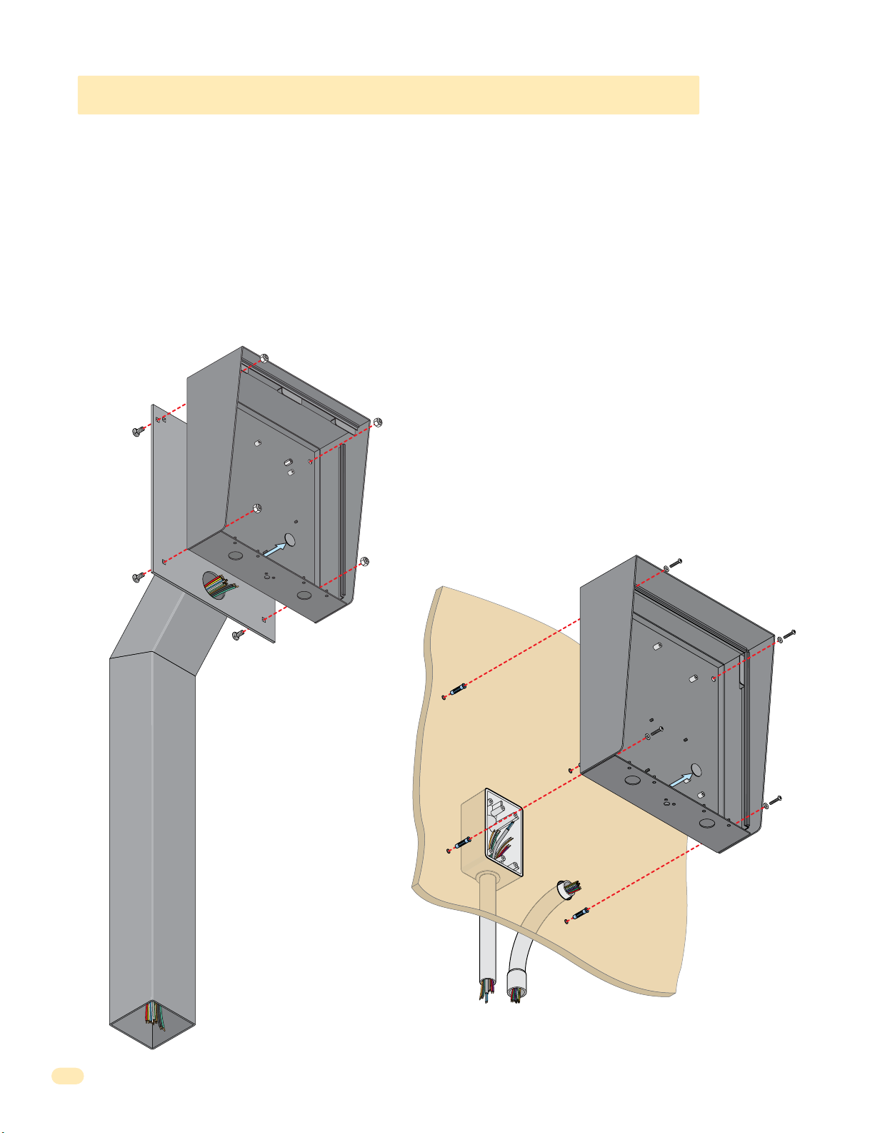
1.1.3 1810 Access Plus Surface Mount Continued
The illustrations below show typical surface mount installations but specific installations can vary from this.
1. Mount the enclosure using the mounting holes provided in the corners. Be sure that mounting screws (Not supplied) do not
protrude into the enclosure where they could cause a short on the back of the circuit board. Make any necessary conduit
connections through the back or bottom of the enclosure using the existing conduit knock-outs. DO NOT make any new conduit
holes in the enclosure.
2. Route all wiring through conduit or architectural post (not supplied) into enclosure.
3. Clean out the enclosure. Make sure that all dirt, metal and/or wood debris is removed.
4. Re-install components back into the enclosure (Reverse section 1.1). Use the wiring schematics in the back of this manual to
help re-install the components if necessary. DO NOT apply any power at this time.
Mount to an
Architectural
Mounting
Post
Mounting Hole
Su
rface Mount
Enclosure
Knock-ou
t
Use hardware supplied with
architectural post to secure
enclosure to post.
Note: An architectural
mounting post anchored
in concrete does not
make a good ground.
Mount ON a Surface
(See sections 1.2).
Wall
Use appropriate
hardware to secure
enclosure to the wall
(not supplied).
Mounting Hole
Surface Mount
Enclosur
e
Knock-out
Conduit run
to junction box
Run all wires
inside post.
10
Examples of conduit runs that may be used, depending on how you choose to run
the wiring. Some installations will allow the conduit to be run outside the wall and
connect to the bottom of the enclosure but this is generally NOT recommended.
Conduit
sweep run
1810-162-A-6-16
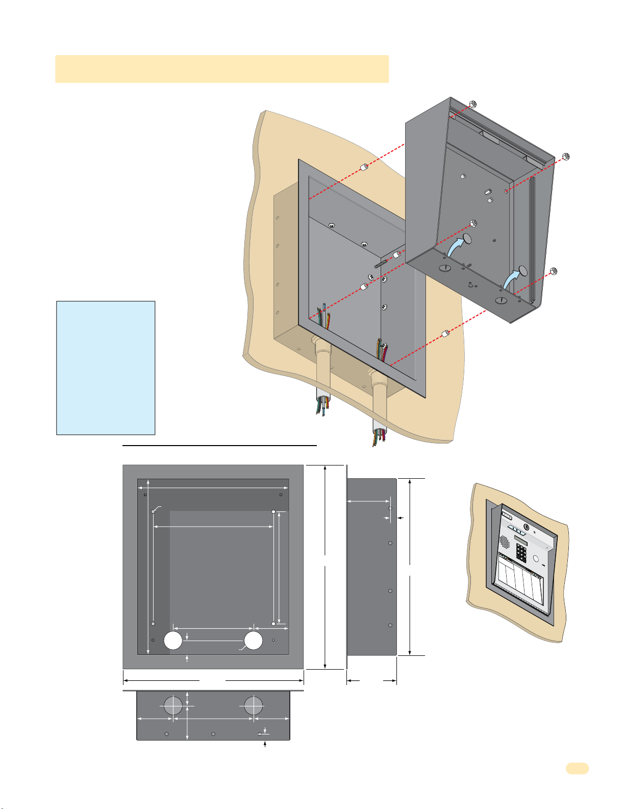
7
8
9
4
5
6
1
2
3
0
1.1.3 1810 Surface Mount Recess Kit
1810 surface mount unit can be recessed
into a wall or pilaster by using the optional
surface mount recess kit if desired (P/N
1803-150). This allows a recessed 1810
telephone entry system to have a lighted
keypad which the flush mount unit DOES
NOT have. The recess box gets installed in
the wall. Use appropriate hardware (not
included) to secure the box in the wall. Run
all necessary conduit (not included) to the
recess box. Slide the enclosure in the recess
box and secure it with the hardware included
in the kit. Be sure the unit is mounted
securely and is not subject to vibration from
closing doors or gates.
WARNING! If this entry
system is used to control a
vehicular gate with an
automatic gate operator, the
entry system must be
mounted a minimum of ten
(10) feet away from the gate
and gate operator, or in
such a way that a person
cannot operate the entry
system and touch the gate
or gate operator at the same
time.
Recess Box
Front View
Mount In a Surface
Wall
Plastic Spacer
Mounting Screws (Not supplied)
Recess
Box
Side View
Locknut
Surface Mount
Enclosure
Knock-outs
1810-162-A-6-16
25” Dia. Mounting Hole
13.25”
1”
1.125”
2.625”
2.5”
Bottom View
11.25”
9”
6”
1.375” Dia.
13.375”
6”
Threaded Stud
2.625”
2.625”
.4”
8.5”
15.25”
3.2”
.4”
Mounting
Holes
.25” Dia.
3.625”
13.25”
1
2
3
4
5
7
6
8
9
0
N
A
M
E
A
d
a
m
s
J
A
k
i
n
s
M
A
n
n
e
s
e
N
C
J
A
A
O
M
n
D
d
E
EN
e
r
s
D
o
o
n
A
0
r
p
H
l
0
a
p
A
9
n
l
M
e
d
g
E
T
D
a
t
o
A
e
1
w
B
u
B
1
y
s
n
5
e
t
w
i
r
n
a
s
D
r
D
M
d
u
B
3
L
b
C
a
5
r
l
a
sb
e
2
r
u
d
a
i
C
i
l
l
u
D
l
O
M
o
g
u
B
D
h
5
P
k
C
a
E
e
5
B
s
a
s
1
s
r
n
D
J
e
E
y
2
n
B
N
P
C
9
g
6
C
e
0
A
O
h
5
j
o
M
a
D
a
6
l
r
r
l
E
E
i
d
n
I
E
s
L
1
l
J
l
B
G
5
i
0
o
s
C
e
2
8
7
r
r
o
W
d
0
l
8
l
i
a
y
n
7
n
e
J
r
F
M
0
a
R
J
B
2
r
2
o
C
a
e
8
5
2
r
g
r
o
d
0
n
1
o
r
en
3
a
d
F
r
u
d
F
l
L
0
a
ar
J
E
B
7
3
o
D
C
r
i
2
l
5
o
2
r
l
o
i
g
0
w
1
n
u
e
1
g
r
n
M
t
s
F
s
E
C
8
e
e
L
K
B
2
O
rn
n
2
C
l
r
8
e
D
4
4
o
B
a
r
i
0
9
E
a
k
n
n
i
4
e
d
n
D
r
e
s
G
T
z
3
G
a
K
B
4
S
0
r
4
D
n
r
2
f
2
4
7
o
s
e
S
B
r
o
w
n
J
B
r
o
w
n
K
B
r
y
a
n
t
W
B
y
ro
n
R
B
y
a
n
G
N
i
o
a
e
3
6
6
b
l
A
l
t
1
d
l
o
M
i
c
n
S
G
E
h
7
a
B
L
3
B
5
rr
0
a
D
3
6
2
0
R
m
e
a
2
4
3
a
e
n
b
9
u
e
i
e
se
B
J
G
l
s
4
e
L
4
D
R
6
n
1
a
D
1
4
7
t
1
R
n
a
r
7
7
2
d
y
e
w
2
i
g
D
M
l
s
e
G
6
r
J
o
L
1
B
7
2
n
a
D
2
3
6
9
R
z
n
e
a
6
3
2
d
e
L
l
3
e
m
e
a
r
z
h
H
s
i
n
a
9
H
a
L
S
e
g
1
4
b
8
a
D
C
t
4
M
0
4
o
e
2
R
n
i
l
2
l
P
4
D
9
i
l
1
l
o
n
M
3
D
2
i
x
4
o
n
D
2
D
3
o
1
m
i
n
3
D
3
o
2
n
i
c
1
D
1
o
7
n
n
D
o
n
t
O
r
8
8
n
g
e
f
D
1
st
e
s
S
E
l
s
d
r
H
e
o
5
g
a
A
L
m
4
8
m
i
e
e
2
0
1
R
v
u
B
m
0
3
0
i
o
n
8
R
4
e
l
e
l
1
r
i
n
H
D
V
1
s
e
L
2
0
n
e
A
0
2
3
d
S
w
1
6
2
r
c
i
i
4
s
2
h
x
8
u
B
K
H
s
7
i
t
L
r
3
e
9
d
u
2
r
9
0
S
c
A
8
S
6
6
i
e
d
8
8
e
i
7
l
e
B
H
y
1
i
i
c
M
t
8
J
3
k
c
6
a
3
8
h
S
P
n
0
8
8
e
J
c
6
8
l
l
i
3
e
n
H
k
c
i
2
k
i
G
M
P
tc
3
4
H
2
a
7
5
h
S
s
8
6
1
h
F
t
8
8
i
a
n
3
e
e
H
r
D
3
r
o
M
R
3
K
1
d
3
a
0
3
S
g
s
5
1
5
e
h
to
5
8
s
a
1
e
n
n
A
H
r
k
8
F
o
D
M
F
3
0
o
5
o
6
4
S
v
7
z
9
6
e
i
i
m
3
r
7
n
1
a
H
o
J
n
3
J
e
M
s
0
n
2
2
s
u
L
4
7
S
e
4
c
7
6
m
n
e
3
5
r
i
5
D
t
a
J
h
0
o
J
M
J
6
h
1
4
n
u
2
9
S
0
s
l
2
5
o
i
o
n
5
4
m
n
5
B
J
a
M
0
o
c
N
0
h
h
0
ab
5
n
4
9
S
H
0
s
0
9
t
o
o
e
8
2
r
e
n
2
l
K
J
e
T
4
o
N
9
F
n
6
a
0
e
4
S
b
s
6
0
t
u
o
5
A
r
l
0
l
J
a
J
3
c
o
N
4
h
n
4
e
1
e
4
S
H
u
s
7
7
y
m
9
G
n
1
a
f
o
n
8
l
n
N
7
A
0
i
J
9
x
0
T
0
o
o
6
2
n
m
1
R
l
i
5
n
P
5
s
7
a
o
7
4
To
t
n
0
t
5
e
7
m
L
r
6
s
p
o
0
s
n
P
3
o
5
e
F
2
n
4
T
r
1
e
o
6
A
0
z
m
0
F
p
4
s
P
1
o
5
e
9
n
0
T
t
3
r
1
y
S
o
3
l
e
l
4
l
r
i
A
Q
R
3
a
3
W
y
2
0
a
J
1
s
3
h
i
n
2
g
1
W
t
o
2
1
a
n
2
s
9
G
h
i
n
5
g
4
W
t
o
0
3
e
n
0
n
7
K
t
L
9
8
Wh
1
7
3
i
4
t
i
n
g
3
M
5
Wi
6
2
0
n
9
s
t
o
n
Wy
F
3
8
a
9
t
t
J
6
7
9
2
1
1
6
7
0
4
4
1
11
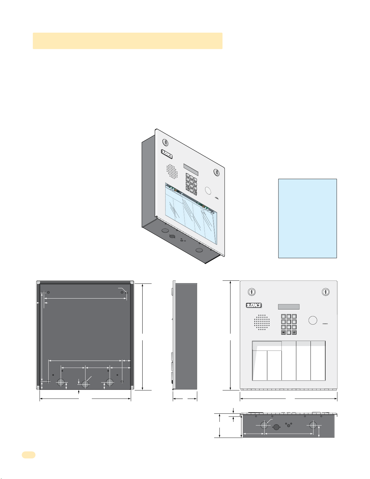
7
8
9
4
5
6
1
2
3
0
Op
er
a
ting Inst
ructions
cate
Code Number On Direct
or
y
ess Co
d
e
Num
ber. I
f Line
Is Busy
, Pr
ess Any Bu
t
ton
Hang-Up.
T
ry
Ag
a
in.
nt
er
On
“OP
EN” Display or
T
one
.
J
M
e
J
so
n
H
e
g
a
te
B
n
D
b
a
u
g
h
B
s
J
a
r
I
rl
in
J
rn
a
r
d
E
llin
g
s
L
ro
k
e
r
T
B
ro
s
e
S
B
ro
wn
J
B
ro
wn
K
B
ry
a
n
t
W
B
y
ro
n
R
B
y
a
n
G
0
0
9
1
1
5
3
5
2
5
5
1
6
5
6
0
7
8
2
2
1
3
2
1
2
4
9
4
7
6
0
0
3
1
1
2
2
9
2
8
2
2
4
9
1
3
2
4
2
3
1
3
3
2
1
1
7
C
OD
E
NAME
B
ye
rs
M
C
ard
i
ll
o
P
C
arn
e
y
P
C
o
l
lin
s
G
C
o
l
y
e
r
R
C
o
rd
u
la
D
C
o
u
rt
E
C
ra
in
s
G
Da
lt
o
n
B
Da
n
i
el
s
R
Dawl
s
J
De
L
a
h
a
e
M
Di
ll
P
Di
l
lo
n
M
Di
x
o
n
D
Do
min
i
c
k
P
Do
n
i
c
k
P
Do
n
n
e
r
K
Do
n
t
e
r
F
8
0
7
5
0
3
5
0
1
4
0
4
4
6
1
2
4
9
7
7
2
6
3
3
4
8
1
1
0
4
3
2
2
0
6
8
8
8
8
5
1
8
3
5
8
4
6
7
7
6
5
9
5
4
9
9
2
C
ODE
NA
M
E
Do
r
l
a
n
d
T
Do
w
n
w
a
rd
L
Du
b
re
u
il
M
Du
k
e
s
D
E
n
g
h
a
r
d
L
E
llis
W
F
a
ra
g
o
F
F
a
rr
o
w
M
F
e
rna
n
d
e
z S
Garf
ie
l
d
S
Garrea
u
J
Gen
tr
y
M
Go
n
za
lez
H
Hab
e
r
f
e
ld
A
Hamme
r
V
He
n
d
r
i
x
K
Hir
d
A
Hit
c
h
J
Hit
c
h
F
Ho
d
g
es
A
Ho
o
v
e
r
H
J
e
n
s
e
n
D
J
o
h
n
s
o
n
M
J
o
h
n
s
o
n
T
J
o
n
e
s
A
J
o
n
e
s
G
2
9
0
1
5
2
0
2
8
0
7
2
8
2
8
3
4
2
7
3
3
44
1
6
1
2
9
1
4
5
4
2
1
2
0
7
3
2
1
8
6
2
3
2
3
3
3
8
3
5
3
0
2
0
6
4
0
0
5
4
9
0
3
4
1
8
7
9
5
5
7
0
3
2
4
1
9
C
ODE
N
A
ME
J
o
rd
an
M
J
o
rd
en
L
J
o
rg
en
s
e
n
B
K
l
e
i
n
D
K
n
o
b
li
c
h
B
L
a
mb
B
L
a
n
d
D
L
a
n
d
e
rs
S
L
a
n
g
s
tr
o
m
B
L
e
v
in
e
D
L
e
w
is
B
L
u
c
id
i
B
Ma
n
c
in
i
G
Ma
sti
n
D
Ma
s
t
o
n
F
Mo
zi
n
a
J
Muc
e
r
a
J
Mulin
B
N
a
b
o
r
K
N
a
b
u
r
J
N
e
u
m
a
n
n
J
N
ix
o
n
R
P
at
t
e
r
s
o
n
F
P
erez F
Pe
t
ro
ll
i
A
R
a
y
J
0
2
6
9
9
6
3
3
8
4
7
6
1
0
1
0
6
9
2
4
7
1
2
2
0
4
0
6
4
0
4
4
7
0
0
6
7
4
5
5
4
6
5
0
1
3
3
0
2
1
1
5
4
3
9
8
7
3
5
2
R
e
s
s
e
g
ie
u
R
R
o
l
l
in
s
A
S
ch
u
st
e
r
S
S
ee
le
y
J
Se
l
le
c
k
H
S
h
ae
r
R
S
h
a
n
k
D
Simo
n
s
L
S
mit
h
J
S
o
m
a
c
h
H
St
e
e
le
F
S
t
o
lla
c
h
H
S
yn
fo
l
A
T
o
ml
i
n
s
o
n
L
T
o
mps
o
n
A
T
o
mps
o
n
S
Ty
le
r
Q
W
a
s
h
in
g
t
o
n
G
W
a
s
h
in
g
to
n
K
W
e
n
t
L
W
h
it
in
g
M
W
in
st
o
n
F
W
y
a
t
t
J
0
8
1
1
4
8
8
8
7
0
6
3
8
8
3
5
5
1
7
3
1
4
3
5
0
5
5
0
8
2
6
5
0
7
9
1
0
2
1
0
7
6
1
0
0
3
3
4
2
1
3
2
2
9
0
0
7
1
3
4
6
0
9
3
8
9
6
7
9
2
1
1
6
7
0
4
4
1
1.1.4 1810 Access Plus Flush Mount
9
6
3
0
Flush mount 1810 is installed with a flush mount kit P/N 1814-165 (stainless) or 1814-166 (gold). Flush mount kits are NOT
INCLUDED with the flush mount entry system (See next page for flush mount kit installation).
The flush mount units may also be installed ON the surface of a wall with a flush mount surface mounting kit if desired P/N
1814-152 (silver only). Flush mount surface mounting kits are NOT INCLUDED with the flush mount entry system (See page 14
for flush mount surface mounting kit installation).
DoorKing offers a self-standing lighted kiosk for the flush mount unit ideal for walk-up pedestrian applications P/N 1200-170
(See page 15 for self-standing kiosk installation).
Flush mount 1810 is installed into a wall/kiosk and can be mounted outside, exposed to the weather. It is preferred that they
have limited direct exposure to the weather. We suggest that when they are mounted outdoors, it is in a covered protected area.
Be sure the unit is mounted securely and is
not subject to vibration from closing doors
or gates.
The flush mount unit DOES NOT have a
lighted keypad.
1
2
3
4
5
7
Creating Printed Directories for 1810 unit:
The Access Plus Account Manager software
will print a directory for the 1810 Access
Plus. The directory can then be easily
inserted into the unit’s directory slot.
6
1
.
Lo
Op
cate
2
.
P
er
Code Number On Direct
ress Co
a
ting Inst
to Hang-Up.
d
3.
e
En
Num
t
er
ber. I
On
NA
T
ry
ME
Ag
“OP
f Line
A
a
d
EN” Display or
in.
a
ms
J
A
k
in
s
M
A
n
n
e
s
e
J
A
C
n
OD
d
e
E
rs
o
n
A
H
p
p
0
l
0
e
9
g
a
te
A
u
B
s
1
t
1
i
n
5
D
B
a
ls
3
5
b
2
a
u
g
B
h
a
B
s
5
s
5
1
J
B
e
ja
6
5
r
6
I
B
e
rl
0
in
7
8
J
B
e
rn
2
2
a
1
r
d
E
B
i
llin
3
2
g
1
s
L
B
ro
2
k
4
e
9
r
T
B
ro
4
s
7
e
S
B
ro
0
wn
0
J
B
ro
1
wn
K
B
ry
2
a
n
t
W
B
y
ro
8
n
R
B
y
a
n
G
1810 Flush Mount
8
9
0
ructions
or
y
Is Busy
, Pr
ess Any Bu
T
NA
one
M
E
.
Do
r
NAME
l
a
t
n
ton
d
T
Do
w
B
n
ye
w
rs
a
Du
rd
M
L
b
C
re
ard
u
il
i
Du
ll
M
C
o
ODE
P
k
C
e
arn
s
D
e
E
y
n
g
P
2
C
o
l
lin
C
o
l
y
C
o
rd
C
o
C
ra
Da
6
Da
3
Dawl
1
2
9
2
2
2
4
9
1
3
2
4
2
3
1
3
3
2
1
1
7
N
h
9
C
a
A
0
ODE
r
ME
d
E
L
s
llis
G
1
J
5
W
o
2
rd
8
0
e
r
R
u
la
u
rt
E
in
s
lt
o
n
n
i
el
s
De
L
a
Di
ll
P
Di
l
lo
Di
x
Do
Do
Do
Do
an
F
7
a
M
ra
0
J
2
g
o
8
o
rd
5
F
0
en
F
3
a
L
rr
0
D
J
o
7
o
w
2
rg
5
M
0
en
F
1
e
s
rna
8
e
K
2
n
8
l
n
e
B
4
d
i
n
0
e
Garf
4
z S
G
B
s
R
J
h
a
e
n
M
o
n
D
min
n
i
c
k
n
n
e
n
t
e
D
3
K
4
ie
2
n
l
4
d
o
6
S
b
Garrea
1
li
c
7
h
L
3
B
a
3
mb
2
u
4
J
Gen
9
B
44
L
tr
a
1
y
n
7
M
d
7
Go
2
D
6
n
L
1
za
a
2
lez
n
6
d
3
Hab
e
3
H
rs
9
M
i
c
k
P
r
r
L
e
S
1
r
a
4
f
n
4
e
g
8
ld
Hamme
1
1
0
He
4
n
d
3
2
Hir
2
d
0
6
Hit
8
c
P
8
8
Hit
8
5
1
Ho
8
K
3
5
Ho
8
F
4
6
J
7
e
7
6
J
5
9
5
J
4
9
9
2
R
s
A
tr
e
s
5
o
s
L
4
m
e
e
2
g
B
v
ie
in
r
R
V
e
o
D
l
1
l
in
L
2
e
r
0
i
x
K
A
h
J
c
h
F
d
g
es
o
v
e
r
n
s
e
n
o
h
n
s
o
h
n
s
J
o
n
e
J
o
n
e
s
w
0
2
is
S
6
ch
B
7
u
L
3
st
u
2
c
9
id
9
S
6
i
ee
B
1
le
Ma
8
y
6
3
n
3
c
Se
8
in
l
i
2
le
G
Ma
3
c
2
4
sti
7
S
6
n
h
ae
D
3
Ma
3
r
3
1
s
0
t
A
S
o
1
h
n
a
8
F
n
Mo
3
5
0
zi
H
6
Simo
n
9
a
3
J
Muc
0
2
2
D
4
e
S
7
r
mit
a
0
J
Mulin
6
4
o
1
n
2
S
M
2
B
o
m
0
N
0
5
a
o
b
0
n
o
4
St
r
T
0
e
K
4
N
9
s
0
a
A
b
6
u
4
S
r
0
t
o
J
3
N
4
s
1
e
G
u
4
m
4
S
7
a
yn
n
8
n
N
7
9
ix
J
0
o
0
n
T
6
o
R
5
P
5
7
at
7
t
e
4
T
r
5
s
o
0
n
P
3
2
erez F
F
5
4
T
6
4
Pe
1
9
t
5
ro
0
1
ll
i
A
R
a
y
3
3
J
0
2
1
1
5
4
3
9
8
7
3
5
2
u
R
0
8
1
A
1
4
8
e
r
S
8
8
7
J
0
6
3
k
H
8
8
3
R
5
5
k
1
D
7
3
n
1
s
L
4
3
h
5
J
0
5
a
5
c
h
H
0
e
8
le
2
F
6
lla
5
0
c
h
H
7
fo
9
1
l
A
ml
0
2
i
1
n
s
o
n
o
mps
L
0
7
6
o
n
o
A
mps
1
0
0
o
n
Ty
S
le
3
r
3
4
Q
W
a
2
s
1
h
3
in
g
W
t
o
a
n
2
s
G
2
h
9
in
g
W
to
e
n
0
n
K
0
t
7
L
W
h
1
it
3
in
4
g
M
W
in
6
st
0
9
o
n
W
F
y
3
a
8
t
t
9
J
6
7
9
2
1
1
6
7
0
4
4
1
WARNING! If this entry
system is used to control a
vehicular gate with an
automatic gate operator, the
entry system must be
mounted a minimum of ten
(10) feet away from the gate
and gate operator, or in
such a way that a person
cannot operate the entry
system and touch the gate
or gate operator at the same
time.
10.875”
1”
.5”
25” Dia. Mounting Hole
10.125”
9”
3”
.5”
.875”
3”
.875” Dia
.875”
11.25”
2.625”
1.125”
Side ViewBack View Front View
11223
44556
77889
0
13.5”13”
Operating Instructions
1. Locate Code Number On Directory
2. Press Code Number. If Line Is Busy, Press Any Button
to Hang-Up. Try Again.
3. Enter On “OPEN” Display or Tone.
NAME
CODE NAME
Adams J
009
Byers M
Akins M
115
Cardillo P
Annese J
352
Carney P
Anderson H
551
Collins G
Applegate B
656
Colyer R
Austin D
078
Cordula D
Balsbaugh B
221
Court E
Bass J
321
Crains G
Bejar I
249
Dalton B
Berlin J
476
Daniels R
Bernard E
003
Dawls J
Billings L
112
DeLahae M
Broker T
292
Dill P
Brose S
822
Dillon M
Brown J
491
Dixon D
Brown K
324
Dominick P
Bryant W
231
Donick P
Byron R
332
Donner K
Byan G
117
Donter F
3”
CODE NAME
NAME
Jordan M
Dorland T
290
Jorden L
Downward L
152
Jorgensen B
Dubreuil M
028
Klein D
Dukes D
072
Knoblich B
Enghard L
828
Lamb B
Ellis W
342
CODE
733
Land D
Farago F
807
441
Landers S
Farrow M
503
612
Langstrom B
Fernandez S
501
914
Levine D
Garfield S
404
542
Lewis B
Garreau J
461
120
Lucidi B
Gentry M
249
732
Mancini G
Gonzalez H
772
186
Mastin D
Haberfeld A
633
232
Maston F
Hammer V
481
333
Mozina J
Hendrix K
104
835
Mucera J
Hird A
322
302
Mulin B
Hitch J
068
064
Nabor K
Hitch F
888
005
Nabur J
Hodges A
518
490
Neumann J
Hoover H
358
341
Nixon R
Jensen D
467
879
Patterson F
Johnson M
765
557
Perez F
Johnson T
954
032
Petrolli A
Jones A
992
419
Ray J
Jones G
12”
.25”
.875” Dia
3”
2.75”
2.625”
6”
Bottom View
CODE NAME
023
562
647
736
408
803
026
996
338
476
101
069
247
122
040
640
447
006
745
546
501
330
211
543
987
352
CODE
Reese D
081
Reiger B
148
Remington S
887
Ressegieu R
063
Rollins A
883
Schuster S
551
Seeley J
731
Selleck H
435
Shaer R
055
Shank D
082
Simons L
650
Smith J
791
Somach H
021
Steele F
076
Stollach H
100
Synfol A
334
Tomlinson L
213
229
Tompson A
007
Tompson S
134
Tyler Q
609
Washington G
389
Washington K
679
Went L
211
Whiting M
670
Winston F
441
Wyatt J
1.5”
12
1810-162-A-6-16
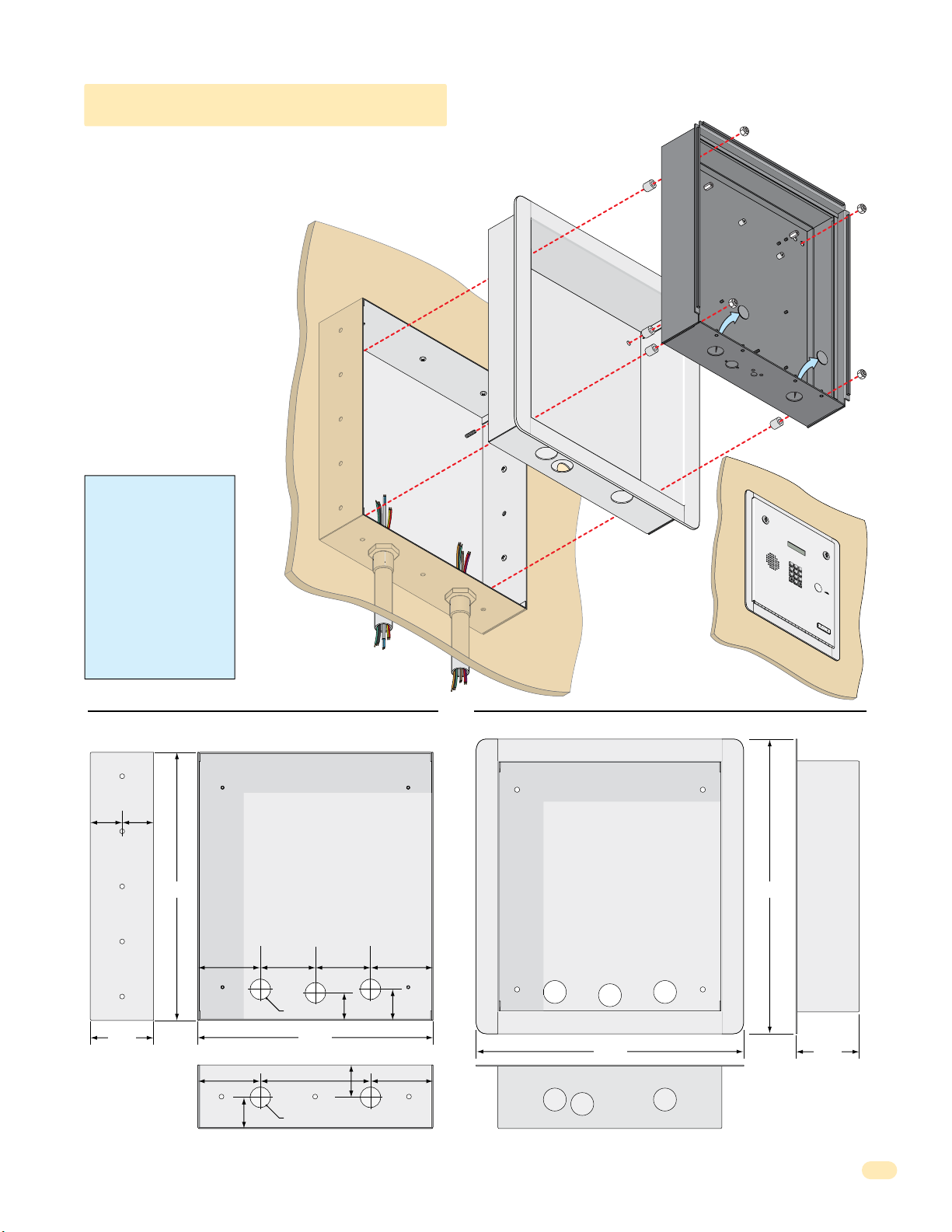
7
8
9
4
5
6
1
2
3
0
O
P
E
R
W
X
Y
Z
TU
V
P
Q
R
S
M
N
O
J
K
L
G
H
I
D
E
F
A
B
C
S
P
1.1.4 1810 Flush Mount Kit
The flush mount kit has two
parts; the rough-in box and the
trim ring. The rough-in box is
installed in the wall first. Use
appropriate hardware (not
included) to secure the box in the
wall. Run all necessary conduit
(not included) to rough-in box.
Slide the trim ring into the
rough-in box. Slide the enclosure
in the trim ring and secure them
all together with the hardware
included in the kit. Be sure the
unit is mounted securely and is
not subject to vibration from
closing doors or gates. See
previous page for flush mount
enclosure dimensions.
WARNING! If this entry
system is used to control a
vehicular gate with an
automatic gate operator, the
entry system must be
mounted a minimum of ten
(10) feet away from the gate
and gate operator, or in
such a way that a person
cannot operate the entry
system and touch the gate
or gate operator at the same
time.
Mount In a Surface
Wall
Rough-In
Box
Mounting Screws
(Not supplied)
Plastic Spacer
Trim
Ring
Locknut
Flush Mount
Enclosure
Knock-outs
T
E
L
E
PH
O
NE
E
N
T
RY
SYS
S
P
1
A
B
C
2
D
G
E
H
F
I
3
4
J
K
L
5
P
M
Q
N
R
O
S
6
7
TU
V
8
W
X
Y
Z
9
OP
E
R
0
O
1.
PE
Loc
R
2.
at
A
P
e
T
re
C
I
ode
N
s
s
P
G
C
re
I
o
Nu
3.
s
de
NST
s
m
Enter
“#”
N
ber
um
R
t
on
ber
UCT
on
o
H
D
.
T
ang
irec
one.
I
f
Line
U
t
P.
i
T
s
r
y
A
g
ai
T
E
M
I
O
N
or
S
y
.
B
us
y
,
n.
M
ODE
L
1
8
0
3
Side View
1.74” 1.71”
Mounting
Holes
.25” Dia.
3.45”
Rough-In Box Trim Ring
Front View
Threaded Stud
14.6” 16”
1.5”
3.4”
1.685”
Mounting
Hole
3.4”
3”
3”
1.125” Dia
12.8”
3.4” 3.4”
1.74”
6”
1.8”
1.125” Dia
Front View
Hole for Threaded Stud
14.7”
Bottom ViewBottom View
Side View
3.45”
1810-162-A-6-16
13
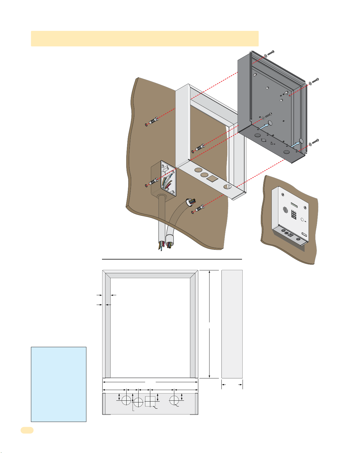
7
8
9
4
5
6
1
2
3
0
O
P
E
R
W
X
Y
Z
T
U
V
P
Q
R
S
M
N
O
J
K
L
G
H
I
D
E
F
A
B
C
S
P
1.1.4 1810 Flush Mount Surface Mounting Kit
Flush mount unit can be mounted ON a
wall or pilaster and NOT IN the wall by
using the optional flush mount surface
mounting kit (P/N 1814-152). This is
useful when cutting a large hole into a wall
or pilaster would be very difficult (marble
or granite for example). The flush mount
surface mounting kit is a trim ring that fits
around the flush mount enclosure. The
enclosure and trim ring get installed
directly on the wall using appropriate
hardware (not included) after running all
necessary conduit to the enclosure. Be
sure the unit is mounted securely and is
not subject to vibration from closing
doors or gates.
The flush mount unit DOES NOT have a
lighted keypad.
Examples of some
small holes in the
wall that may be
needed, depending
on how you choose
to run the wiring.
to junction box
Trim Ring
Mount On a Surface
Wall
Trim Ring
Conduit run
Conduit
sweep
run
Mounting Screws
(Not supplied)
Flush Mount
Enclosure
Knock-outs
T
E
L
E
PH
O
1.
PE
Loc
2.
at
P
e
re
s
s
P
re
3.
s
s
Enter
O
NE
E
N
T
RY
SYST
E
M
S
P
1
A
B
C
2
DE
GH
F
I
3
4
J
K
L
5
P
MN
Q
R
O
S
6
7
TU
V
8
WX
Y
Z
9
O
P
E
R
0
R
A
T
C
I
ode
N
G
C
I
o
Nu
de
NST
m
“#”
N
ber
um
R
t
on
ber
UCT
on
o
H
D
.
T
ang
irect
one.
I
f
I
O
Line
U
N
or
P.
S
y
i
.
Tr
s
y
B
A
us
gain.
y
,
M
ODEL
1
8
0
3
WARNING! If this entry
system is used to control a
vehicular gate with an
automatic gate operator, the
entry system must be
mounted a minimum of ten
(10) feet away from the gate
and gate operator, or in
such a way that a person
cannot operate the entry
system and touch the gate
or gate operator at the same
time.
14
.375”
.875”
1”
12”
1.5”
1.5”3” 3” 3”
1.125”
1.125” Sq
Bottom View
Side ViewFront View
13.5”
2.625”
1”
.875”
1.125” Dia
1810-162-A-6-16
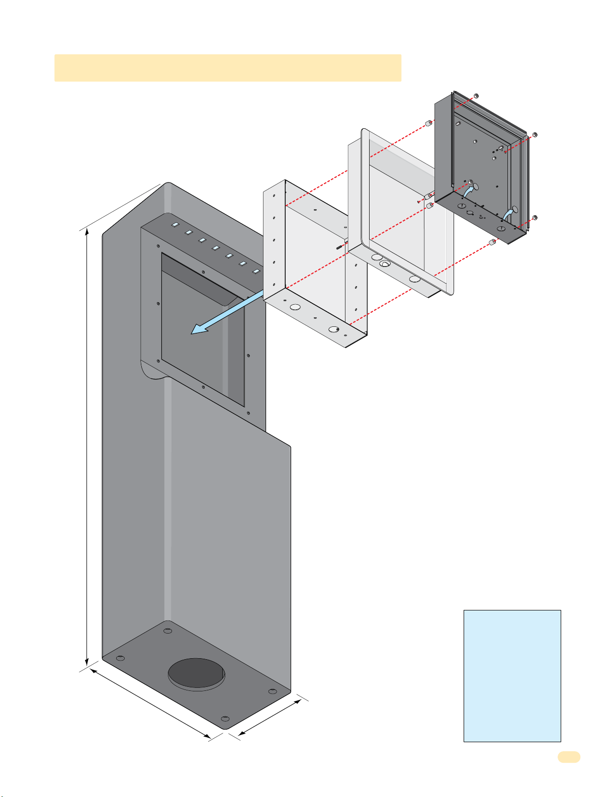
1.1.4 1810 Self-Standing Lighted Kiosk
The flush mount kit (Sold separately, see previous page) is installed into
the self-standing kiosk (P/N 1200-170) to secure the flush mount 1810
in place.
Secure the rough-in box in the kiosk. Run all necessary wires to
rough-in box. Slide the trim ring into the rough-in box. Slide the
enclosure in the trim ring and secure them all together with hardware
included in the kit.
Rough-In
Box
Plastic Spacer
Trim
Ring
Locknut
Flush Mount
Enclosure
Knock-
outs
60”
18
.5”
10
WARNING! If this entry
system is used to control a
vehicular gate with an
automatic gate operator, the
entry system must be
mounted a minimum of ten
(10) feet away from the gate
and gate operator, or in
such a way that a person
cannot operate the entry
”
system and touch the gate
or gate operator at the same
time.
1810-162-A-6-16
15
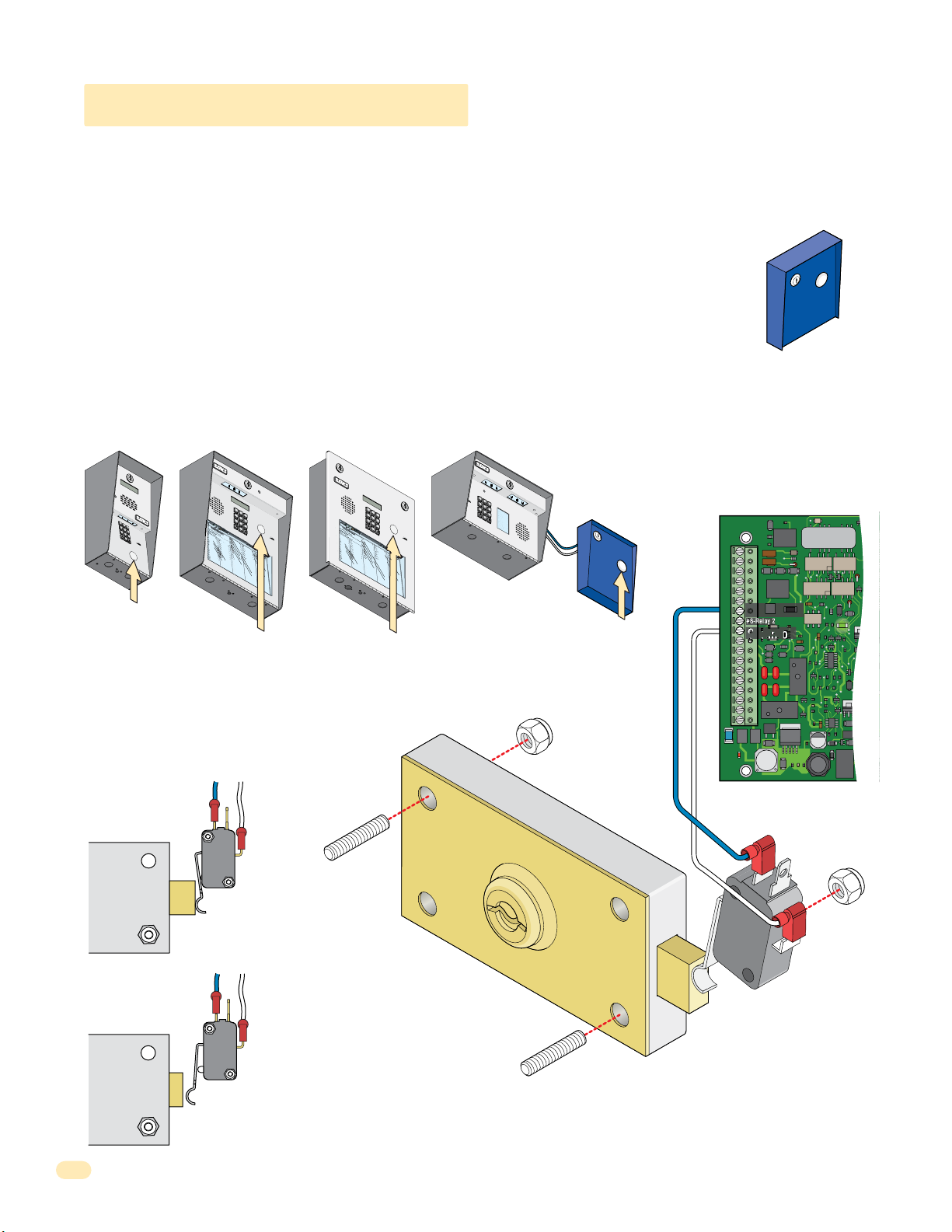
7
8
9
4
5
6
1
2
3
0
1.2 Postal Lock Installation
7
8
9
4
5
6
1
2
3
0
2
3
1
33
2
11
7
D
i
x
on
D
D
o
m
i
ni
c
k
P
D
oni
c
k
P
D
o
nne
r
K
D
ont
e
r
F
32
2
068
8
8
8
518
3584
67
76
5
954
99
2
H
e
ndr
i
x
K
H
i
r
d
A
H
i
t
c
h
J
H
i
t
c
h
F
H
o
d
g
e
s
A
H
oo
v
e
r
H
J
e
ns
e
n
D
J
oh
ns
on
M
J
ohns
o
n
T
J
on
e
s
A
J
on
e
s
G
7
32
18
6
2
32
333
8353
02
06
4
00
5
49
0
3
41
8
7
9
5
57
0
32
419
L
e
w
i
s
B
L
uc
i
d
i
B
M
a
n
c
i
ni
G
M
a
s
t
i
n
D
M
a
s
t
o
n
F
M
oz
i
na
J
M
u
c
e
r
a
J
M
ul
i
n
B
N
a
bo
r
K
N
a
bu
r
J
N
e
um
a
nn
J
N
i
x
o
n
R
Pa
t
t
e
r
s
on
F
P
e
r
e
z
F
P
e
t
r
o
l
l
i
A
R
a
y
J
026
9
9
6
3
38
4
7
6
101
0
6
9
2
47
12
2
0406
40
44
7
00
6
745
546
50
1
33
0
2
1
1
5
4
3
98
7
352
R
o
l
l
i
ns
A
S
c
h
us
t
e
r
S
S
e
e
l
e
y
J
Se
l
l
e
c
k
H
S
h
a
e
r
R
Sh
a
nk
D
S
i
m
o
n
s
L
S
m
i
t
h
J
S
o
m
a
c
h
H
S
t
e
e
l
e
F
S
t
ol
l
a
c
h
H
S
y
n
f
o
l
A
To
m
l
i
n
s
on
L
T
o
m
ps
on
A
T
om
ps
o
n
S
T
y
l
e
r
Q
W
a
s
hi
ng
t
on
G
W
a
s
hi
n
g
t
o
n
K
W
e
nt
L
W
hi
t
i
ng
M
W
i
ns
t
o
n
F
W
y
a
t
t
J
148
8
87
06
3
883
551
7
31
435
0
5
5
08
2
650
79102
1
076100
334
2
13
22
9
0
0
7
1
3
4
6
0
9389
67
9
2
11
6
7
0
44
1
7
8
9
4
5
6
1
2
3
0
NAME
Ada
ms
J
Bern
a
r
d
E
Brow
n
L
Da
vi
s T
Hodge
s S
Mil
ler
J
Smith
K
Tho
ma
s
W
Z
im
me
r
R
1
9
5
2
4
6
8
3
7
C
ODE
7
8
9
4
5
6
1
2
3
0
3
2
4
2
3
1
3
3
2
1
1
7
D
il
l
o
n
M
D
i
x
o
n
D
D
o
m
i
n
i
c
k
P
D
o
n
ic
k
P
D
o
n
n
e
r
K
Do
n
te
r
F
1
0
4
3
2
2
0
6
8
8
8
8
5
1
8
3
5
8
4
6
7
76
5
9
5
4
9
9
2
H
a
m
m
e
r
V
H
e
n
d
r
i
x
K
H
i
r
d
A
H
i
tc
h
J
H
it
c
h
F
H
o
dg
e
s
A
H
o
o
v
e
r
H
J
e
n
s
e
n
D
J
o
h
n
s
on
M
J
o
hn
s
o
n
T
J
o
n
e
s
A
J
o
n
e
s
G
1
2
0
7
3
2
1
86
2
3
2
3
3
3
8353
0
2
0
6
4
0
0
5
4
9
0
3
4
1
8
79
5
5
7
0
3
2
4
1
9
L
e
v
i
n
e
D
L
e
w
is
B
L
uc
i
d
i
B
M
a
n
c
i
n
i
G
M
a
s
t
in
D
M
a
s
t
on
F
M
o
z
i
n
a
J
M
uc
e
r
a
J
M
u
l
i
n
B
N
a
b
o
r
K
N
a
b
u
r
J
N
e
u
m
a
n
n
J
N
ix
o
n
R
P
a
t
t
e
r
s
o
n
F
P
e
r
e
z
F
P
e
tr
o
ll
i
A
R
a
y
J
8
0
3
0
2
6
99
6
33
8
4
7
6
10
1
0
6
9
2
4
7
1
2
2
0
4
0
6
4
0
4
4
7
0
0
6
7
4
5
5
4
6
5
0
1
3
3
0
2
1
1
5
4
3
9
8
7
3
5
2
R
e
s
s
e
g
ie
u
R
R
ol
li
n
s
A
S
c
h
u
s
t
e
r
S
S
e
e
le
y
J
S
e
l
l
e
c
k
H
S
h
a
e
r
R
S
h
a
n
k
D
S
i
m
o
n
s
L
S
m
i
t
h
J
S
o
m
a
c
h
H
S
te
e
l
e
F
S
to
l
l
a
c
h
H
S
y
n
fo
l
A
T
o
m
li
n
s
o
n
L
T
o
m
p
s
o
n
A
T
o
m
p
s
o
n
S
T
y
le
r
Q
Wa
s
h
i
n
g
t
on
G
Wa
s
h
i
n
g
t
on
K
We
n
t
L
W
h
i
t
in
g
M
W
in
s
t
o
n
F
W
y
a
tt
J
0
8
1
1
4
8
8
8
7
0638
8
3
5
5
1
7
3
1
4
3
5
0
5
5
082
65
0
7
9
1
0
2
1
0
7
6
1
0
0
3
3
4
2
1
3
2
2
9
0
0
7
1
3
4
6
0
9
3
8
9
6
79
2
1
1
6
7
0
4
41
At some locations, such as gated communities, it will be necessary to provide access to the mail carrier so that they can
deliver the mail. Mail carrier access will be provided by the installation of an Arrow Postal Lock. This is the same lock that the
Post Office uses for gang mailboxes. These locks are not available to the public. The installer or the building owner/manager
will have to call the Post Office and arrange for the installation of this lock into the access plus system. DoorKing 1802 & 1810
access plus systems are designed to accept installation of the postal lock. If you are using the 1808 and need postal service
access, use the DoorKing Postal Lock Box wired to #7 & #9 shown below, P/N 1402-080 postal box sold separately.
Prior to installation of the postal lock, be sure power to the access plus system is turned OFF.
1. Remove the hole plug on the faceplate of the telephone entry system.
2. Cut the wire tie wrapped around the switch ONLY when installing postal lock.
POSTAL
CK BOX
LO
3. Remove the two hex nuts from the postal lock-mounting studs. Mount postal lock on the studs and secure with the hex nuts.
When the lock is installed, the pawl of the lock, in the extended position is depressing the switch. When the mail carrier inserts
his key and turns the postal lock, the pawl is withdrawn into the lock and the switch will activate Relay 1 for the programmed
strike time. Note: Postal switch can activate Relay 2 when connected to #8 & #9 if desired.
1
2
3
4
5
7
6
1808
NAME
Ada
8
ms
C
Bern
ODE
J
9
a
r
Brow
d
E
1
n
Da
0
L
vi
9
s T
Hodge
5
Mil
s S
ler
2
Smith
J
4
Tho
K
ma
6
Z
s
im
W
me
8
r
R
3
7
POSTAL
LOCK BOX
Postal Box
Hole Plug
g
g postal
n
n
Existi
1970-010
J1
1
2
3
4
5
6
7
8
9
10
11
12
13
14
15
16
17
18
OV
#7-Relay 1
#8-Relay 2
Common
J4
1
2
3
4
5
6
7
8
lock-mounti
nuts.
1
2
3
4
5
7
1
2
3
4
5
6
7
8
9
OPE
INS
RATIN
0
1.
Lo
T
R
c
UC
a
G
D
t
e
i
TION
r
2
Code
e
.
ct
Pres
o
ry
S
N
s
.
If
u
Code
mber o
Li
n
e
B
N
ut
i
s
t
u
on
B
n
mb
Try Aga
us
to
y
er
3
,
H
.
P
.
E
ang
r
n
e
in
te
ss
.
r
U
A
o
p
ny
n
.
T
o
n
e
.
Hole Plug
1802
6
8
1
9
2
0
3
N
A
ME
H
R
e
o
ndr
l
D
l
L
i
ns
i
e
x
i
w
32
x
on
026
A
i
K
H
s
S
2
D
i
c
B
r
h
7
d
2
3
1
33
11
1810 Surface Mount
148
D
us
L
32
A
o
uc
t
m
068
9
e
i
r
9
d
i
H
S
ni
6
i
S
i
e
t
B
c
c
e
18
8
k
D
h
l
M
87
e
P
oni
6
2
y
J
a
8
3
n
J
8
38
c
c
H
Se
8
k
i
i
ni
t
P
c
l
2
06
l
D
h
e
G
M
32
c
o
7
3
F
a
k
nne
518
4
s
H
7
t
H
S
i
6
n
o
r
h
d
D
333
a
K
883
D
g
e
M
ont
r
e
a
s
35
R
101
s
A
t
e
H
Sh
o
8
r
oo
n
F
8
a
551
F
v
nk
M
35
e
oz
r
4
0
D
H
67
6
i
J
S
na
9
e
i
ns
m
3
7
J
M
02
o
31
e
n
n
u
76
s
2
c
D
47
e
L
J
S
5
r
oh
m
a
06
435
J
ns
i
M
t
h
4
ul
on
954
J
12
i
n
J
S
M
2
ohns
o
B
00
m
0
N
5
a
5
a
5
o
c
99
bo
04
h
n
J
S
H
2
T
r
0
on
t
K
e
49
08
e
e
N
l
s
e
0
a
2
A
bu
F
6
40
J
S
r
on
t
J
ol
3
650
e
N
l
41
s
a
e
c
G
um
h
44
S
H
7
a
y
nn
n
8
79
f
N
7
o
9
i
J
1
l
x
00
A
o
n
To
6
R
m
5
02
Pa
57
l
i
n
1
t
s
745
t
e
on
T
r
o
s
on
m
L
0
07
P
32
ps
e
F
6
r
on
546
e
z
T
om
A
F
419
100
P
ps
e
t
o
50
r
o
n
T
l
1
y
l
S
i
l
e
A
334
R
r
a
Q
y
33
J
W
0
a
2
s
13
hi
ng
2
1
W
t
1
on
a
22
s
G
hi
9
n
5
g
4
W
t
3
o
e
n
0
nt
K
0
7
L
98
W
7
hi
1
t
3
i
ng
4
352
M
W
i
ns
6
0
t
9
o
n
W
F
y
38
a
t
t
9
J
67
9
2
11
6
7
0
44
1
Hole Plug
1
2
3
4
5
7
6
8
1
9
2
0
3
H
R
a
e
m
s
D
s
L
m
e
il
e
g
l
v
1
e
o
8
ie
i
r
0
n
n
0
H
R
4
V
u
e
3
M
e
ol
R
D
n
1
3
2
4
2
3
1
3
3
2
1
1
7
0
li
D
d
L
2
8
n
i
r
e
0
1
x
s
i
w
3
x
o
0
A
2
n
is
2
K
H
S
2
6
B
D
i
c
r
h
7
d
1
D
u
L
3
4
A
o
s
uc
2
8
t
m
0
99
e
i
6
r
d
i
H
S
n
8
6
i
S
i
e
i
tc
B
c
e
1
8
k
D
le
h
M
86
8
P
o
y
7
J
a
n
8
33
n
J
ic
8
c
H
S
8
k
8
i
it
n
e
P
l
c
i
2
06
l
D
e
h
G
M
3
c
o
2
3
F
a
k
n
5
4
s
n
1
H
7
t
H
S
e
in
8
6
o
r
h
dg
a
D
3
K
8
Do
e
M
3
8
r
e
3
3
a
n
s
3
R
10
s
te
5
A
t
H
S
on
8
r
1
o
h
F
o
a
83
5
F
n
v
M
5
e
k
5
1
o
r
4
0
D
z
H
6
6
i
J
S
n
7
9
e
a
i
m
n
3
7
J
s
M
0
o
3
e
2
n
1
n
uc
76
s
2
D
4
e
L
J
S
5
7
r
o
m
a
h
0
4
J
i
n
M
6
t
3
h
s
4
5
on
u
9
J
1
l
5
i
2
n
J
S
4
M
2
o
o
B
hn
m
0
0
N
0
5
a
s
5
a
5
c
o
9
b
0
h
n
9
o
4
J
S
H
2
T
r
0
o
te
K
n
4
082
e
e
N
9
l
s
e
0
a
A
b
F
6
u
4
J
S
r
0
o
to
J
n
3
65
l
e
N
4
l
s
a
1
e
0
c
G
u
h
4
m
4
S
H
7
a
y
n
n
8
7
n
fo
N
79
9
ix
1
J
l
0
A
o
0
n
T
6
o
R
m
5
0
P
5
2
li
7
a
n
1
t
s
7
t
e
o
4
T
r
n
5
o
s
o
m
L
0
0
n
P
3
7
p
2
e
6
F
s
r
o
5
e
n
4
z
T
6
o
A
F
m
4
1
P
1
0
p
9
e
0
s
tr
o
5
o
n
0
T
ll
1
y
S
i
le
3
A
R
r
3
a
Q
4
y
3
3
J
Wa
0
2
s
1
h
3
i
n
2
g
1
Wa
t
1
on
2
s
G
2
h
9
i
n
5
g
4
We
t
3
on
0
n
K
0
t
7
L
9
8
W
7
h
1
i
t
3
in
4
g
3
5
M
W
2
in
6
s
0
t
9
o
n
W
F
y
3
a
8
tt
9
J
6
79
2
1
1
6
7
0
4
41
1810 Flush Mount
Hole Plug
Extended Pawl
NC
Com
Pawl
Blue Wire
N.C. #7
White Wire
Com #9
Lock
0
02 & 181
Withdrawn Pawl
NC
Com
s
Factory wired Postal
Switch in 18
or inside Postal Lock Box
sold separately.
2 & 1810
sting postal lock-mounting stud
i
located inside the faceplate of
Relay Activates
Ex
16
the 180
sold separately.
or inside Postal Lock Box
1810-162-A-6-16
 Loading...