

Page 1
Direct Vent Fireplace Insert
Jøtul GI 535 DV IPI
New Harbor
High Altitude Adjustment
Instructions
Kit 157886 Manual Valve - LP
Kit 157887 Manual Valve - NG
This kit shall be installed by
a qualified service agency in
accordance with the manufacturer’s
instructions and all applicable
codes and requirements of the
authority having jurisdiction. If the
information in these instructions
is not followed exactly, a fire,
explosion, or production of carbon
monoxide may result causing
property damage, personal
injury or loss of life. The qualified
service agency is responsible for
the proper installation of this kit.
The installation is not proper and
complete until the operation of
the adjusted appliance is checked
as specified in the manufacturer’s
instructions supplied with the kit.
Cet équipement de conversion sera
installé par une agence qualifiée de
service conformément aux instructions du fabricant et toutes exigences
et codes applicables de l’autorisés
avoir la juridiction. Si l’information
dans cette Instruction n’est pas suivie
exactement, un feu, explosion ou production de protoxyde de carbone peut
résulter le dommages causer de propriété, pert ou blessure personnelle
de vie. L’agence qualifiée do service
est esponsable de l’installation propre de cet équipemetn. L’installation
n’est pas propre et complète jusqu’à
l’operation de l’appareil converi est
chéque suivant les critères établis
dans les instruction de propriétaire
provision nées avel l’équipement.
CAUTION: Before proceeding
with this conversion, the gas
supply must be shut off prior to
disconnecting the electrical power.
Jøtul North America, Inc. 55 Hutcherson Dr. Gorham, Maine 04038
ATTENTION: Avant de procéder à cette
conversion, l’approvisionnement en
gaz doit être coupée avant de débrancher l’alimentation électrique.
May, 2016 139778_R01
Page 2
High Altitude Adjustment
When installing this appliance at altitude above 2000
feet, it is necessary to compensate for the thinner air
(less volume of air per cubic foot). Higher altitudes affect
the atmospheric pressure and heat value of gaseous
fuels. The lower oxygen content in the air and the lower
gas viscosity require the use of a different orifice to
achieve efficient, clean combustion at the burner tube.
In the U.S.
THE DERATING KIT MUST BE INSTALLED BY AN AUTHORIZED SERVICE TECHNICIAN IN ACCORDANCE WITH THE
MANUFACTURER’S INSTRUCTIONS AND ALL CODES AND
REQUIREMENTS OF THE AUTHORITY HAVING JURISDICTION. THE INFORMATION STICKER MUST BE FILLED OUT
BY THE INSTALLER AND APPLIED TO THE APPLIANCE AT
THE TIME OF THE CONVERSION. THE QUALIFIED SERVICE
AGENCY PERFORMING THIS WORK ASSUMES RESPONSIBILITY FOR THIS DE-RATING.
In Canada
This unit has been tested for installation at high altitudes in accordance with Canadian test standard CAN/
CGA-2.17. THE DERATING SHALL BE CARRIED OUT IN
ACCORDANCE WITH THE REQUIREMENTS OF THE PROVINCIAL AUTHORITIES HAVING JURISDICTION AND IN
ACCORDANCE WITH THE REQUIREMENTS OF THE CAN1B-149.1 AND .2 INSTALLATION CODE.
GAS
NATURAL
GAS
PROPANE
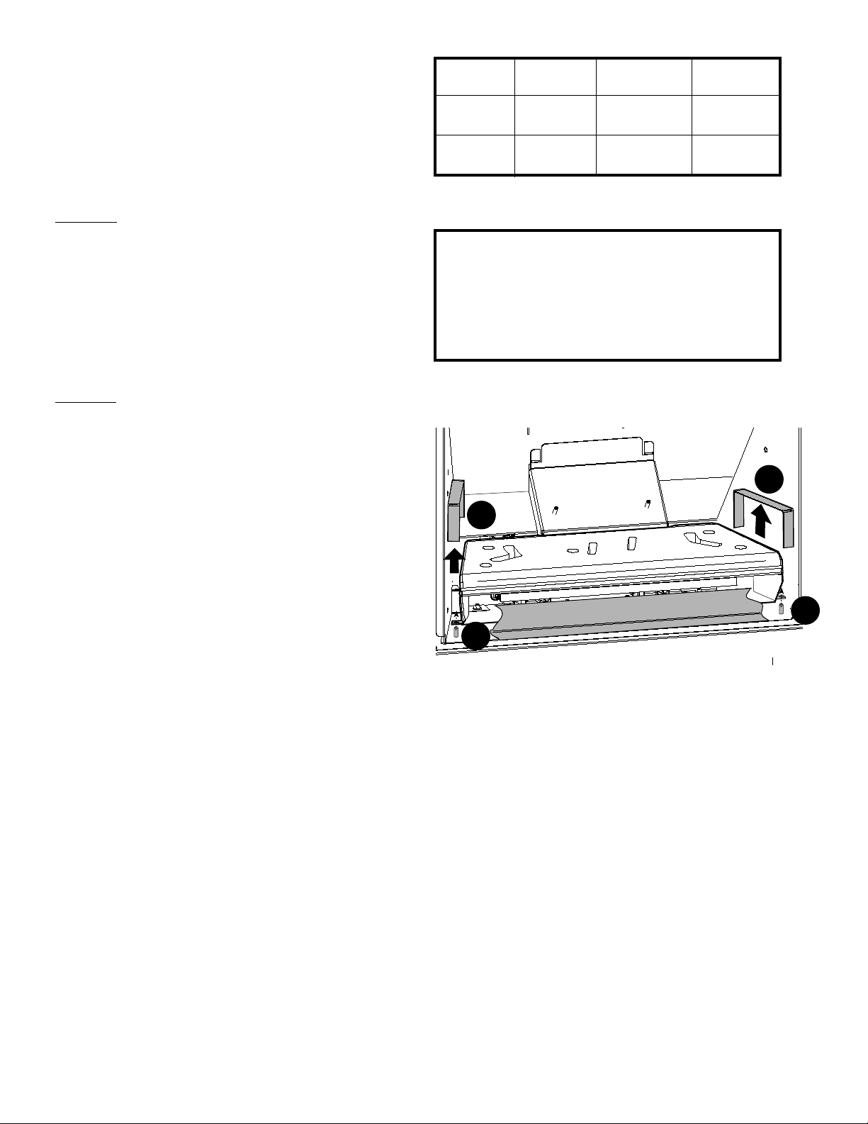
Table 1. High Altitude Orifice Chart.
THIS APPLIANCE HAS BEEN CONVERTED FOR USE
AT AN ALTITUDE OF ______________________
Orifice Size: _______ Manifold Press: ________
Input, BTU/Hr: ________ Fuel Type: _________
Date of Conversion: ______ / _______ / ______
Figure 1. High Altitude Conversion Notice Label
ORIFICE SIZE
#48 - Left
#49 - Right
#56 - Left
#57 - Right
ELEVATION
2001’- 4500’
(611 - 1170 m)
2001’- 4500’
(611 - 1170 m)
220977 - Right
A
JØTUL PART
NO.
229407 - Left
129411 - Right
129466- Left
A
High Altitude Installations:
2000 ft. to 4500 ft. installations (or 610 m - 1370 m)
See Table 1.
For high altitude installations consult the local gas
distributor or the authority having jurisdiction for proper
rating methods. If the installer must convert the unit
to adjust for varying altitudes, the information label
included with this kit must be completed by the installer
and applied to the appliance at the time of the conversion. See fig. 1.
Derating procedure
1. Turn off the gas supply and electrical power to the
appliance.
2. Use the Latch Tool to remove the glass frame.
3. RETRACT THE AIR SHUTTERS: Locate the Air Shutter
cables on the floor in each side compartment - push each
cable fully in. This action retracts the shutters and allows
the burner to be disengaged from the firebox. See fig. 3.
4. REMOVE THE BURNER:
Lift out the two steel support shelves, fig. 2, (A),
located at each side of the burner. Grasp the burner
assembly at the sides, lifting it straight up, then tilt
it back to disengage it from the injectors and front
locator studs (B). Pull the assembly up out of the
firebox.
B
B
Figure 2. Burner removal and replacement.
5. Use a 1/2” deep well socket or open end wrench to
remove the original injectors and replace with the
appropriate ones from this kit as specified in Table 1
above.
6. Attach the high altitude conversion sticker provided to
the rating plate on the appliance. See figure 1.
7. REINSTALL THE BURNER ASSEMBLY. Tilt the back of
the burner down to engage the air shutters with the
injectors. Set the burner in place, engaging the front
brackets with the studs in the firebox floor, fig. 1, (B).
Replace the steel side support shelves, fig. 1, (A).
BE CERTAIN THE BURNER IS LEVEL AND SECURELY
SEATED ON THE FIREBOX FLOOR. Properly located, it
should not be able to move in any direction.
8. Use an electronic gas detector or soap solution to test
for leaks at the pilot head and all gas line joints.
NEVER USE AN OPEN FLAME TO CHECK FOR GAS LEAKS.
2
Page 3

Figure 3. Injector conversion.
Pilot Assembly
Front Burner Air
Shutter Cable
Front Burner
Injector
Air Shutter
Adjustor Trays
Rear Burner
Injector
Rear Burner Air
Shutter Cable
Gas Pressure Check
Correct gas pressure is essential for efficient and safe
operation of the stove. It is important that the correct
pressure is established at the time of the installation.
Proper gas pressure provides a consistent flow of gas to
the appliance and is instrumental in checking for gas
leaks.
Pressure Test: Attach a manometer to the
appropriate test point on the valve. See fig. 4. The
gauge connections are located on the front of the valve.
Connections are identified by:
E - for Inlet or Supply Pressure (the amount of gas
coming to the valve.)
A - for Manifold Pressure (the amount of gas that
is coming out of the valve to the burner.)
Figure 4.
Pressure test points.
ManifoldInlet
OUT
INLET GAS PRESSURES
(inches water column)
MIN MAX
NATURAL GAS 5.0 7.0
PROPANE 12.0 14.0
The appliance and its appliance main gas valve
must be disconnected from the gas supply piping
system during any pressure testing on that system
at test pressures in excess of 1/2 psig (3.5 kPa).
The appliance must be isolated from the gas
supply line by closing its individual manual gas
shut-off valve (gas cock) during any pressure testing
of the gas supply piping system that is equal to or
exceeds pressures of 1/2 psig (3.5 kPa).
MANIFOLD PRESSURES
(inches water column)
MIN MAX
NATURAL GAS 1.1 3.8
PROPANE 2.9 11.0
Integrated Gas Cock
An in-line gas cock is built into the left side firebox
compartment, just upstream from the gas valve. Use
the fireplace Latch Tool to open and close the gas cock.
See figs. 5 an 6 on page 4.
Pilot Adjustment
3
Page 4

Figure 5.
Insert the Latch Tool into the receiver hole in
the gas cock.
Fig. 6. Pull the tool forward toward you to open the gas
cock. Push it back to close the gas cock.
4
 Loading...