

Page 1

X-908
Anleitung
Page 2

Page 3

Inhalt
Sicherheitshinweise
Eigenschaften
Komponenten
Netzteileinbau
Reinigung des Staubfilters
Festplatteneinbau
Mainboardeinbau
2,5" Festplatteneinbau
Einbau Wasserkühlung
Grafikkartenhalter
Frontanschlüsse
Anschlusskabel
Anschluss der Lüfter
Anschluss der RGB / PWM Steuerplatine
Fehlerursachen
Kontaktinformation
2
3
4
5
5
5
5
6
7
8
9
10
10
11
11
12
1
Page 4
Sicherheitshinweise
Vielen Dank für den Kauf eines Gehäuses der Firma Inter-Tech. Mit dem Kauf des X-908 haben Sie ein hochwertiges Computergehäuse erworben, das mit vielen, individuell einstellbaren Lichteffekten aufwartet und zudem
reichlich Platz für Festplatten und große Grafikkarten bietet.
Dieses Gehäuse ist ausschließlich für die Montage von Computern und für den Gebrauch innerhalb geschlossener
Räume vorgesehen.
Wir empfehlen Ihnen diese Anleitung aufmerksam durchzulesen und den Anschluss der eingebauten Lüfter und
Steuerungen genau nach dieser Anleitung vorzunehmen.
Für Schäden, die aufgrund der Nichtbeachtung dieser Anleitung entstanden sind, übernehmen wir keine Haftung.
Bewahren Sie die Anleitung auf um bei einer Um-Konfiguration darauf zurückgreifen zu können.
Vergewissern Sie sich bei Arbeiten am Gehäuse, dass dieses vom Stromnetz getrennt ist.
Da LEDs mit niedriger Spannung arbeiten fliest in ihnen ein hoher Strom um die gewünschte Leistung zu erhalten.
Dadurch erhöht sich bei unsachgemäßer Installation oder Handhabung die Brandgefahr. Stellen Sie daher sicher,
dass alle Kabel fest eingesteckt und richtig angeschlossen sind, bevor Sie den Computer in Betrieb nehmen.
Sollten Sie beim Betrieb des Computers merkwürdige Geräusche oder Gerüche wahrnehmen, bzw. eine Rauchentwicklung entdecken, trennen Sie den Computer schnellstmöglich vom Stromnetz.
Wir empfehlen bei längerer Nichtbenutzung oder Abwesenheit den Computer komplett vom Stromnetz zu trennen.
Wenn Sie das Computergehäuse entsorgen wollen oder müssen, entsorgen Sie es bitte nicht über den Hausmüll,
sondern über die speziellen Sammelstellen für Elektroaltgeräte. Bei Fragen dazu wenden Sie sich bitte an Ihre
Gemeinde-/ Stadtverwaltung oder befragen Sie Ihren Fachhändler. Die anfallenden Verpackungsreste von Pappe
und Kunststoffen entsorgen Sie bitte über die entsprechenden Sammelbehälter Ihres Hausmülls.
Wir gewähren auf dieses Produkt die gesetzliche Gewährleistung. Im Falle eines Garantiefalls wenden Sie sich
bitte an Ihren Fachhändler von dem Sie das Produkt erworben haben. Die genauen Garantiebedingungen finden
Sie auf unserer Internetseite: www.inter-tech.de.
2
Page 5
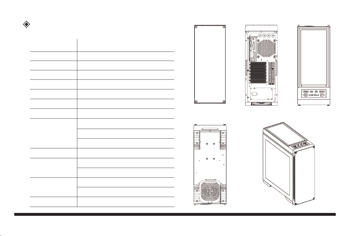
Eigenschaften
Farbe
Abmessungen
Material
M/B Typ
5.25" Laufwerke
HDD Laufwerke
Slots
max. Höhe CPU Kühler
Einbaumöglichkeit
für Lüfter
Staubfilter
Frontanschlüsse
RGB+PWM Steuerung
Schwarz
210(B)x527(H)x512(T)mm
Stahl/ABS
E-ATX/ATX/Micro-ATX/ITX
0
3x 3.5”HDD/3x 2.5”SSD
7 Slots, unterstützt VGA Karten bis 420mm
160mm
Top: 3x 120mm (2x eingebaut)
Vorne: 2x 120mm (optional)
Hinten: 1x 120mm (eingebaut)
1x Gehäuseboden; 1x Top
2x USB3.0 Typ A, 2x USB3.0 Typ C
HD Audio/MIC
5x RGB LED
5x Geschwindigkeitsregelung
Standard ATX PSU Netzteil (optional)
Front Rückseite Top
Unterseite Seite
3
Page 6
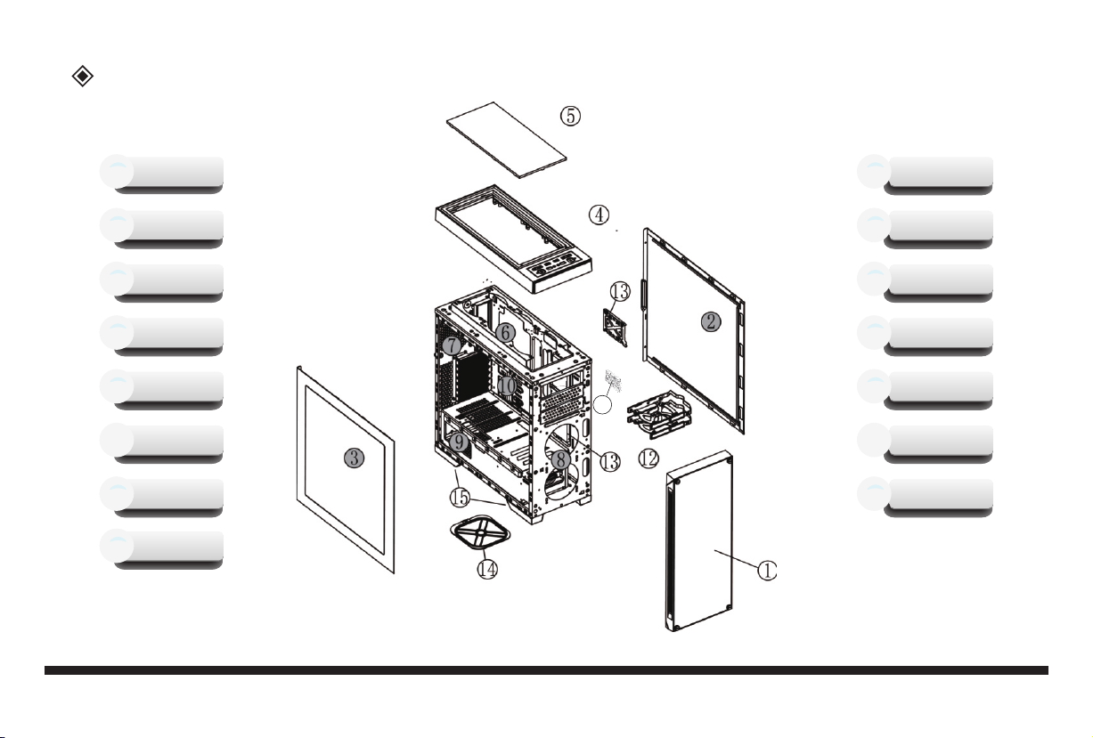
Komponenten
Frontblende
1
Li. Seitenteil
3
Staubfilter, oben
5
Lüfter
7
Netzteil, optional
9
RGB+PWM
11
Steuerplatine
SSD, optional
13
Standfüße
15
11
Re. Seitenteil
2
Deckel
4
Lüfter
6
Lüfter, optional
8
Mainboard, optional
10
HDD, optional
12
Staubfilter, unten
14
4
Page 7
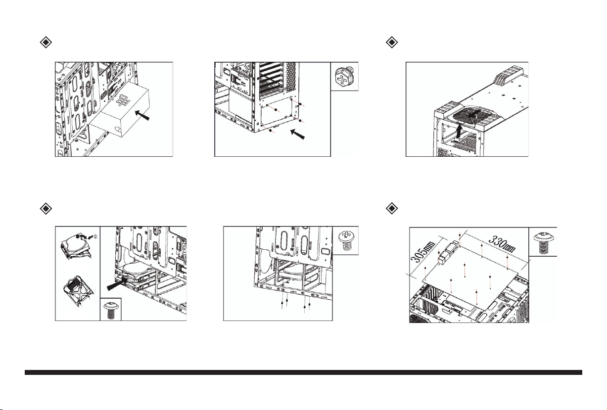
Netzteileinbau
Reinigung des Staubfilters
Netzteil einschieben Befestigen am Gehäuse
Festplatteneinbau
3,5" einclipsen
2,5" festschrauben
Einbau 3,5" auf dem BodenWechselrahmen herausziehen
Staubfilter nach hinten rausziehen
Mainboardeinbau
Einbau Mainboard auf dem Träger
5
Page 8
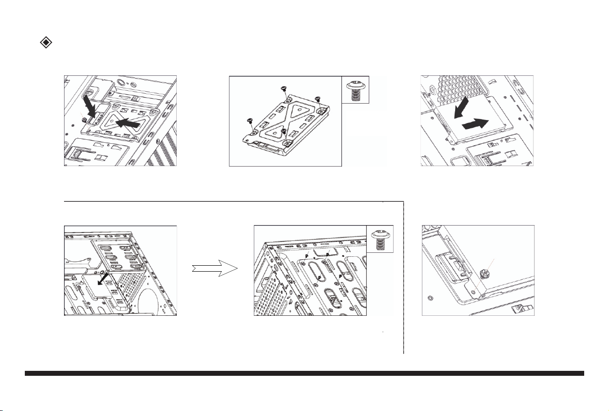
2,5" Festplatteneinbau
SSD Einbaumöglichkeit 1+2
Schraube lösen und Rahmen abnehmen
SSD Einbaumöglichkeit 3+4
SSD anhalten Von Aussen mit Schrauben fixieren
A B
SSD mit Schrauben am Rahmen
befestigen
C
Rahmen wieder einsetzen
D
Mit Schraube befestigen
6
Page 9
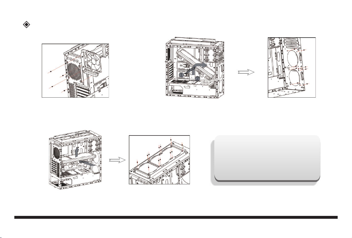
Einbau Wasserkühlung
Möglichkeit 1:
Schrauben Sie den Radiator an der
hinteren Lüfterposition fest
Möglichkeit 3:
Deckel abnehmen.
Setzen Sie den Radiator von unten an den Deckel und schrauben Sie ihn fest.
Möglichkeit 2:
Frontblende abnehmen.
Setzen Sie den Radiator hinter die Frontblende und schrauben Sie ihn fest.
Maße Wasserkühlung:
Front : 240/360mm
Deckel: 240/280mm
Rückseite: 120mm
7
Page 10
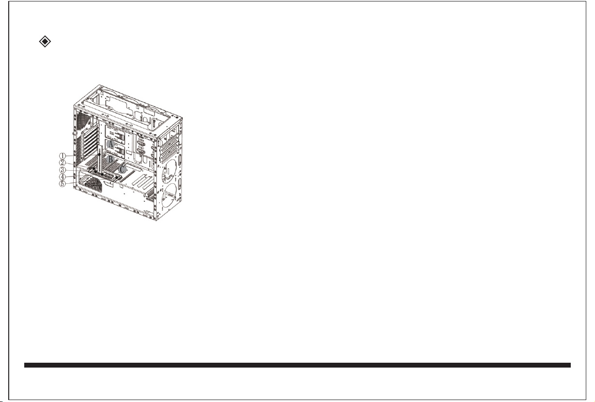
Grafikkartenhalter
Montieren sie erst die Grafikkarte.
Justieren Sie den Grafikkartenhalter entsprechend der verbauten Grafikkarte.
1. Höhenverstellung: Lösen Sie Schraube 1, passen Sie den Ausleger A Ihren Bedürfnissen an und fixieren Sie ihn wieder
2. Tiefenverstellung: Lösen Sie die Schrauben 2+5, passen Sie den Halter C Ihren Bedürfnissen an und fixieren Sie ihn wieder
3. Seitenverstellung: Lösen Sie die Schrauben 3+4, passen Sie den Arm B Ihren Bedürfnissen an und fixieren Sie ihn wieder
8
Page 11

Anschluss der RGB / PWM Steuerplatine
Rainbow5
1
8
FAN 1
FAN 2FAN 3FAN 4FAN 5
Strip 1 - 2
PWM IN
2
7
Rainbow4
Test
Rainbow1
SW
Rainbow1
G
Rainbow2Rainbow3
3
5
5V
D
1 3Pin Anschluss für Lüfter
2 Eingang für PWM Signal vom Mainboard
(CPU Fananschluss)
3 3Pin Anschlüsse für RGB, 5V Digital
4 SYNC Anschluss zum Mainboard
5 Anschluss zum LED-Schalter
6 Strom Eingang (SATA Stecker)
7 Test Jumper für PWM Regelung
8 Anschluss RGB Strip
An den 4pin-Anschlüssen (3) kann sowohl die Beleuchtung von
RGB Lüftern als auch reine RGB Strips angeschlossen werden
6
SATA
MB Rainbow
und dann über den LED Schalter am Gehäuse gesteuert werden. Mit
passenden Verteilern (abhängig von der Leistung des Mainboards)
können an diesen Anschlüssen auch weitere RGB Elemente ange-
4
schlossen werden. Bitte beachten Sie, dass die Gesamtausgangsleistung der Platine 48W pro Farbkanal nicht übersteigen darf.
Bitte beachten Sie das Anschluss-Schema der eingebauten Platine.
Falscher Anschluss kann zur Beschädigung der Platine führen.
Nach dem ersten Einschalten des Computers ist die Lichtsteuerung im Status Aus.
Drücken Sie den Schalter kurz um die Lichtsteuerung einzuschalten.
Die Steuerplatine speichert den zuletzt eingestellten Effekt.
Mit jedem weiteren Tastendruck können Sie das Licht verändern. Zum Wechseln in den Mainboard Sync. Mode drücken Sie den Taster mindestens 3 Sekunden
Zum Ausschalten der RGB Steuerung drücken Sie den LED Schalter länger als 5 Sekunden.
Bei Betrieb der Platine über den Anschluss 4 direkt am Mainboard ist der Schalter über Anschluss 5 außer Funktion.
Fehlerursachen
Der Rechner startet immer neu.
Der Schalter zur Lichtsteuerung funktioniert nicht.
Weder die Lüfter, noch das Licht funktionieren.
Lüfter drehen nicht.
Prüfen Sie ob die Anschlüsse 2 und 4 mit den richtigen Anschlüssen auf dem Mainboard
verbunden sind. Prüfen Sie auch die Polarität der Anschlüsse.
Prüfen Sie ob der Schalter an Buchse 5 angeschlossen ist.
Prüfen Sie ob das Modul über Stecker 6 mit dem Netzteil verbunden ist und Strom bekommt.
Prüfen Sie ob an Anschluss „FAN1" ein Lüfter angeschlossen ist. Einige Mainboards geben ein unsauberes
PWM Signal aus, so dass die Platine dieses nicht interpretieren kann. Sollte das bei Ihnen der Fall sein,
müssen entweder die Lüfter von der Platine getrennt und an den oben liegenden Schaltern des Gehäuses
angeschlossen werden oder eine Brücke auf Jumper 7 gesetzt werden. In diesem Fall drehen die Lüfter
über die Platine mit voller Geschwindigkeit und können nicht mehr geregelt werden.
11
Page 12

Anschlusskabel
Anschluss der Lüfter
HDD LED M/B Anschluss
POWER LED M/B Anschluss
Reset S/W M/B Anschluss
Power S/W M/B Anschluss
Sie haben folgende Möglichkeiten Lüfter im Gehäuse anzuschließen bzw. die Geschwindigkeit zu regeln:
1. Schieberegler auf dem Deckel des Gehäuses
An den beiden Schiebereglern (siehe Seite 9) können 1x ein Lüfter und 1x zwei Lüfter mit 3pin-Anschluss (siehe oben) angeschlossen werden.
Die angeschlossenen Lüfter können durch den Schieberegler in der Geschwindigkeit „AUS“, „50%“ und „100%“ geregelt werden.
An den Schiebereglern können auch beleuchtete Lüfter angeschlossen werden. Die Beleuchtung zusätzlicher Lüfter kann nicht durch das Gehäuse
ohne optionales Zubehör (siehe Produkt-Homepage, Rubrik Zubehör) geregelt werden.
2. An der eingebauten Platine
An der eingebauten Platine, an der Rückseite des Mainboard-Trägers, können bis zu 5 Lüfter mit 3-pin-Anschluss angeschlossen werden.
Die eingebauten sowie 2 zusätzliche Lüfter können über die Platine am Mainboard angeschlossen werden und werden dann über das Mainboard,
temperaturabhängig, geregelt.
4pin Molex Stromanschluss für
manuelle Lüftersteuerung
3pin Lüfter-Anschluss für
manuelle Lüftersteuerung
1x
3x
10
Page 13

Frontanschlüsse
Drücken zum
Öffnen des
Staubfilters
Lüftersteuerung
Power LED
M/B Anschluss
Power Schalter
M/B Anschluss
USB3.0
M/B I/O Anschluss
USB3.0
M/B I/O Anschluss
Lüftersteuerung
Reset Schalter
M/B Anschluss
HDD LED
M/B Anschluss
LED Schalter
H/D Audio
M/B Anschluss
9
Page 14

Page 15

Kontaktinformation
Hainhäuser Weg 93
D-30855 Langenhagen
Tel.: +49 (0) 511 726678-30
Fax: +49 (0) 511 726678-37
E-Mail: vertrieb@inter-tech.de
Fragen, Anregungen oder Wünsche? Melden Sie sich unter www.inter-tech.de/hilfe
12
Page 16

X-908
Manual
Page 17

Werden Sie Teil einer großen Social-Media-Familie und
folgen Sie uns auf unseren Social-Media-Kanälen
für aktuelle Produktnews, Testberichte und Gewinnspiele.
InterTech.de
intertechgmbh
inter-tech
InterTechGmbH
Inter-Tech.de
Page 18

Page 19

Safety instructions
Thank you for purchasing an Inter-Tech case. With the purchase of the X-908 you have acquired a high-quality
computer case, which comes with many, individually adjustable lighng effects and also offers plenty of space
for hard drives and large graphics cards.
This enclosure is exclusively for the installaon of computers and for use within closed rooms provided.
We recommend you to read this manual carefully and to connect the built-in fans and controls according to this
manual.
We accept no liability for damage caused by non-compliance with this manual. Keep the instrucons in order
to be able to use them during a re-configuraon. When working on the case, make sure that it is disconnected
from the mains.
Since LEDs work with low voltage, a high current flows in them to get the desired power. This increases the
risk of fire if improperly installed or handled. Therefore, make sure all cables are securely plugged in and
properly connected before using the computer.
If you experience any strange noises, smells, or smoke during operaon of the computer, disconnect the
computer from the mains as soon as possible. We recommend that the computer be completely disconnected
from the mains during prolonged periods of non-use or absence.
If you want or need to dispose of the computer case, please do not dispose of it with your household waste
but about the special collecon points for old electrical appliances. If you have any quesons, please contact
your municipal / city administraon or consult your dealer.
The accumulang packaging remnants of cardboard and plascs should be disposed of via the corresponding
collecon containers of your household waste. We grant this product the legal warranty. In case of a warranty
claim, pplease contact your dealer from whom you purchased the product. Find the exact warranty terms on
our website: www.inter-tech.de.
2
Page 20

Features
Color
Dimensions
Material
M/B type
5.25" drives
HDD drives
Slots
max. height CPU cooler
Mounting options
for fans
Dust filter
Front connectors
RGB+PWM control
Black
210(W)x512(D)x527(H)mm
Steel/ABS
E-ATX/ATX/Micro-ATX/ITX
0
3x 3.5”HDD/3x 2.5”SSD
7 Slots, up to VGA card with 420mm length
160mm
Top: 3x 120mm (2x included)
Front: 2x 120mm (optional)
Back: 1x 120mm (included)
1x Bottom; 1x Top
2x USB3.0 Typ A, 2x USB3.0 Typ C
HD Audio/MIC
5x RGB LED
5x Speed control
Standard ATX PSU Power supply (optional)
Front Rear Top
Bottom Side
3
Page 21

Content
Safety instructions
Features
Components
Power supply mounting
Dust filter cleaning
HDD mounting
Motherboard mounting
2,5" HDD mounting
Water cooling mounting
Graphic card holder
Front connectors
Connection cables
Fan connecting
Connection RGB / PWM board
Error causes
Contact information
2
3
4
5
5
5
5
6
7
8
9
10
10
11
11
12
1
Page 22

Components
Front panel
1
Left side panel
3
Dust filter, top
5
Fan
7
PSU (optional)
9
RGB+PWM
11
board
SSD, optional
13
Feet
15
11
Right side panel
2
Top cover
4
Fan
6
Fan, optional
8
Motherboard (opt.)
10
HDD, optional
12
Dust filter bottom
14
4
Page 23

Power supply mounting
Dust filter cleaning
Insert power supply Attach to the case
HDD mounting
3,5" clip
2,5" Screws
Pull out HDD tray
Mounting 3,5" at the bottom
Pull out the dust filter
Motherboard mounting
Motherboard mounting on the tray
5
Page 24

2,5" HDD mounting
SSD mounting option 1+2
A B
Release screw and remove frame
SSD mounting option 3+4
Attach SSD Fix with screws from outside
Fix SSD with screws on the frame
C
Insert frame again
D
Fix with screw
6
Page 25

Water cooling mounting
Option 1:
Screw the radiator to the fixed rear fan position.
Option 3:
Remove top cover.
Place the radiator from underneath the top cover and screw it tight.
Option 2:
Remove the front panel.
Place the radiator behind he frontpanel and screw it tight.
Dimensions water cooling:
Front : 240/360mm
Top: 240/280mm
Rear: 120mm
7
Page 26

Front connectors
Press to open
the
dust filter
Fan controls
Power LED
M/B connector
Power switch
M/B connector
USB3.0
M/B I/O connector
USB3.0
M/B I/O connector
Fan controls
Reset switch
M/B connector
HDD LED
M/B connector
LED switch
H/D Audio
M/B connector
9
Page 27

Graphic card holder
First mount the grafics card.
Adjust the grapics card holder according to the build-in graphics card.
1. Height adjustment: Loosen screw 1, adjust the arm A to your needs and fix it again
2. Depth adjustment: Loosen the screws 2 + 5, adjust the holder C to your needs and fix it again
3. Side adjustment: Loosen the screws 3 + 4, adjust the arm B to your needs and fix it again
8
Page 28

Connection RGB / PWM controller
Rainbow5
1
FAN 2FAN 3FAN 4FAN 5
Rainbow4
3
1. 3pin connectors for fans
2. Imput for PWM singal from motherboard (CPU fan connector)
3. 3pin connectors for RGB, 5V digital
4. SYNC connector to mainboard
5. Connector to the LED switch
6. Power input (S-ATA connector)
7. Test jumper for PWM regulation
8. Connector RGB strip
At the 4pin connections (3) both the illumination of RGB fans as well
as pure RGB strips are connected and then controlled by the LED
6
SATA
MB Rainbow
switch on the case. With suitable distributors (depending on the
performance of the mainboard) other RGB elements can be connected
to these ports. Please note that the total output power of the board must
4
not exceed 48W per color channel.
Please note the connection diagram of the built-in board.
Incorrect connection may damage the board.
After turning on the computer for the first time, the light control is in the Off state.
Press the switch briefly to switch on the light control.
The control board stores the last set effect.
Each time you press the button, you can change the light. To change to Mainboard Sync press at least 3 seconds.
To turn off the RGB control, press the LED switch for more than 5 seconds.
When operating the board via port 4 directly on the mainboard, the switch via port 5 is disabled.
Error causes
The computer always reboots
Make sure connector 2 and 4 are plugged correctly and polarity is correct.
8
FAN 1
Strip 1 - 2
PWM IN
2
7
Test
Rainbow1
SW
Rainbow1
G
Rainbow2Rainbow3
5
5V
D
The light control switch does not work
Neither the fans nor the light work
Fans do not turn
Check if the switch is connected to socket 5.
Check if the module is connected to the power supply via plug 6 and gets power
Check if there is a fan connected to port „FAN1“. Some motherboards are sending a faulty PWM- signal and the controller
is not able to process it. In this case you need to disconnect all fans from the controller and connect them to the
PWM-slider on the top of the case. Other solution is to put a jumper on “7”.
Both solution cause the fans to turn at full speed and they can´t be regulated anymore.
11
Page 29

Connection cables
Fan connecting
HDD LED M/B connector
POWER LED M/B connector
Reset S/W M/B connector
Power S/W M/B connector
You have the following options to connect fans in the case or to regulate the speed:
1. Slider on the top of the case
On the two sliders (see page 9) you can connect 1x one fan and 1x two fans with 3pin connection (see above).
The connected fans can be controlled by the slider in the speed "OFF", "50%" and "100%".
Illuminated fans can also be connected to the sliders. The lighting of additional fans can not be controlled without optional accessories (see product
homepage, section Accessories).
2. On the built-in RGB/PWM controller
On the built-in controller on the back of the mainboard carrier, up to 5 fans with 3-pin connection can be connected.
You can regulate the speed of the serial fans and 2 additional ones by connecting them to the controller. The controller will be connected to the
motherboard, this way your fans will be regulated depending on the temperature.
4pin Molex power connector
for manual fan control.
3pin fan connector for
manual fan control.
1x
3x
10
Page 30

Contact information
Hainhäuser Weg 93
D-30855 Langenhagen
Tel.: +49 (0) 511 726678-30
Fax: +49 (0) 511 726678-37
E-Mail: vertrieb@inter-tech.de
Questions, suggestions or requests? Sign in at www.inter-tech.de/hilfe
12
Page 31

Page 32

Become part of a great social media family
and follow us on our social media channels
for current product news, reviews and competitions.
InterTech.de
intertechgmbh
inter-tech
InterTechGmbH
Inter-Tech.de
 Loading...