

Intertec Data Systems WST Series, WST50 EL, WST80 EL, WST119 EL Installation And Maintenance Instructions Manual
Solar DHW Tank / Ballon d'eau chaude solaire
WST Series
Notice:
The heat transfer medium must be nontoxic water with Toxicity Class 1 as
listed in "Clinical Toxicology of Commercial Products," 5th edition.
The heat transfer medium must be limited to a maximum pressure of 30 PSIG
by an approved safety or pressure relief valve.
Avis :
Le liquide caloporteur doit être de l'eau non toxique de classe 1 telle que
précisé dans la 5e édition de « Clinical Toxicology of Commercial Products ».
Le liquide caloporteur doit être limité à une pression maximale de 30 PSIG par
une soupape de sécurité ou de surpression homologuée.
6 720 648 083-00.1ITL
WST50 EL / WST80 EL / WST119 EL
[en] Installation and maintenance instructions for the contractor 2
[fr] Notice d'installation et d'entretien pour installateurs professionnels 20
WARNING:
These installation instructions are intended solely for use by a licensed heating
contractor or service technician. Read all
instructions before installing. Perform
steps exactly in the order given. Failure to
follow these instructions can result in severe injury, death or property damage.
6 720 648 081 (2012/09) US/CA
Conforms to UL 174, IAS 1-91
Certified to CSA C22.2 no. 110
AVERTISSEMENT:
Cette notice d'installation doit être utilisée
uniquement par des installateurs chauffagistes ou des techniciens de maintenance
qualifiés. Lisez attentivement toutes les
consignes avant l'installation. Exécutez les
actions en respectant scrupuleusement
l'ordre indiqué. En cas de non-respect,
vous risquez de subir de sérieuses blessures pouvant conduire à la mort ou d'entraîner de lourds dommages matériels.
Table of Contents
Table of Contents
1 Explanation of symbols and safety information . . . . . . . . 2
1.1 Explanation of symbols . . . . . . . . . . . . . . . . . . . . . . . . . . . . . . 2
1.2 Important safety instructions . . . . . . . . . . . . . . . . . . . . . . . . . 2
2 Product description . . . . . . . . . . . . . . . . . . . . . . . . . . . . . . . 4
2.1 Pack contents . . . . . . . . . . . . . . . . . . . . . . . . . . . . . . . . . . . . . 4
2.2 Product description . . . . . . . . . . . . . . . . . . . . . . . . . . . . . . . . 4
2.3 Intended use . . . . . . . . . . . . . . . . . . . . . . . . . . . . . . . . . . . . . . 4
2.4 Rating plate . . . . . . . . . . . . . . . . . . . . . . . . . . . . . . . . . . . . . . . 5
2.5 Tools, Materials and Accessories . . . . . . . . . . . . . . . . . . . . . . 5
2.6 Symbols and Warnings . . . . . . . . . . . . . . . . . . . . . . . . . . . . . . 5
2.7 Dimensions and connections . . . . . . . . . . . . . . . . . . . . . . . . . 7
2.8 Specifications . . . . . . . . . . . . . . . . . . . . . . . . . . . . . . . . . . . . . 7
2.9 Pressure Drop Curve . . . . . . . . . . . . . . . . . . . . . . . . . . . . . . . 8
3 Moving the Solar Storage Tank . . . . . . . . . . . . . . . . . . . . . . 9
4 Installation . . . . . . . . . . . . . . . . . . . . . . . . . . . . . . . . . . . . . . . 9
4.1 Solar Storage Tank Installation . . . . . . . . . . . . . . . . . . . . . . . 9
4.1.1 Requirements for installation location . . . . . . . . . . . . . . . . . . 9
4.1.2 Positioning the DHW tank . . . . . . . . . . . . . . . . . . . . . . . . . . 10
4.2 Attaching the Bosch solar pump station (optional) . . . . . 10
4.3 Water connections . . . . . . . . . . . . . . . . . . . . . . . . . . . . . . . 10
4.3.1 Installation example . . . . . . . . . . . . . . . . . . . . . . . . . . . . . . 11
4.3.2 Pipe connections to the heat source and DHW network . 11
4.3.3 Temperature and Pressure Relief Valve (TPR)
Blow-off Line . . . . . . . . . . . . . . . . . . . . . . . . . . . . . . . . . . . . 12
4.3.4 Checking for leaks . . . . . . . . . . . . . . . . . . . . . . . . . . . . . . . . 13
4.4 Electrical Connections . . . . . . . . . . . . . . . . . . . . . . . . . . . . 13
4.4.1 Making electrical connections . . . . . . . . . . . . . . . . . . . . . . 13
4.4.2 Grounding Instructions / Connecting the electric heating
element electrically . . . . . . . . . . . . . . . . . . . . . . . . . . . . . . . 13
4.4.3 Setting the electric heating element . . . . . . . . . . . . . . . . . 13
4.4.4 Installing the DHW temperature sensor . . . . . . . . . . . . . . . 14
10 Warranty . . . . . . . . . . . . . . . . . . . . . . . . . . . . . . . . . . . . . . . 18
10.1 Additional terms and conditions of the limited warranty
for domestic hot water tanks (for all applications) . . . . . . 18
10.2 Limited warranty for domestic hot water tank installed
in a commercial application . . . . . . . . . . . . . . . . . . . . . . . . 18
10.3 Additional terms and conditions of the limited warranty
for domestic hot water tanks (for all applications) . . . . . . 18
1 Explanation of symbols and safety
information
1.1 Explanation of symbols
Warnings
Warnings are indicated in the text by a warning triangle
and a gray background.
In case of danger due to electric shock, the exclamation
point on the warning triangle is replaced with a lightning
symbol.
Signal words at the beginning of a warning are used to indicate the type
and seriousness of the ensuing risk if measures for minimizing damage
are not taken.
• NOTICE indicates that minor damage to property may occur.
• CAUTION indicates possible minor to medium personal injury.
• WARNING indicates possible severe personal injury.
• DANGER indicates that severe personal injury may occur.
Important information
Important information that presents no risk to people or
property is indicated with this symbol. It is separated by
horizontal lines above and below the text.
5 Commissioning . . . . . . . . . . . . . . . . . . . . . . . . . . . . . . . . . 14
5.1 Commissioning the solar storage tank . . . . . . . . . . . . . . . . 14
5.2 System installer to inform the owner/operator . . . . . . . . . 14
6 Shutdown . . . . . . . . . . . . . . . . . . . . . . . . . . . . . . . . . . . . . . 15
6.1 Shutting down the solar storage tank . . . . . . . . . . . . . . . . 15
6.2 Shutting down the solar storage tank when there is a
risk of frost . . . . . . . . . . . . . . . . . . . . . . . . . . . . . . . . . . . . . . 15
7 Environmental Protection / Disposal . . . . . . . . . . . . . . . 15
8 Maintenance . . . . . . . . . . . . . . . . . . . . . . . . . . . . . . . . . . . 15
8.1 Checking the magnesium anodes . . . . . . . . . . . . . . . . . . . 15
8.2 Restarting the solar storage tank after maintenance . . . . 16
9 Spare parts list . . . . . . . . . . . . . . . . . . . . . . . . . . . . . . . . . 17
2
Additional symbols
Symbol Meaning
B Sequence of steps
Æ Cross-reference to other points in this document or to
other documents
• Listing/list entry
– Listing/list entry (2nd level)
Table 1
1.2 Important safety instructions
WARNING – When using electrical appliances, basic safety precautions
to reduce the risk of fire, electric shock, or injury to persons should be
followed, including:
1. READ ALL INSTRUCTIONS BEFORE USING THIS WATER HEATER.
2. This water heater must be grounded. Connect only to properly
grounded outlet. See "GROUNDING INSTRUCTIONS" found on section
4.4.2.
3. Install or locate this water heater only in accordance with the provided
installation instructions.
4. Use this water heater only for its intended use as described in this
manual.
WST50 EL / WST80 EL / WST119 EL – 6 720 648 081 (2012/09)
Explanation of symbols and safety information
5. Do not use an extension cord set with this water heater. If no
receptacle is available adjacent to the water heater, contact a qualified
electrician to have one properly installed.
6. As with any appliance, close supervision is necessary when used by
children.
7. Do not operate this water heater if it has a damaged cord or plug, if it
is not working properly, or if it has been damaged or dropped.
8. This water heater should be serviced only by qualified service
personnel. Contact nearest authorized service facility for examination,
repair, or adjustment.
SAVE THESE INSTRUCTIONS
Read all instructions before installing. Perform steps in the order given.
Have this indirect water heater serviced/inspected by a qualified service
technician, at least annually. Failure to comply with the above could
result in severe personal injury, death or substantial property damage.
Installation and conversion
B Risk of fire through soldering and welding!
Take appropriate protective measures when soldering and welding as
the thermal insulation is flammable; for example, cover the thermal
insulation.
B Ensure that the solar storage tank is installed or converted only by an
authorized contractor.
B Use installation materials that are sufficiently heat-resistant.
Installation and commissioning
B In the Commonwealth of Massachusetts this tank must be installed by
a licensed plumber or gas fitter.
B The power supply must be connected by a licensed electrician. The
wiring diagram must be followed.
B Do not install this device in rooms with high moisture exposure (e.g.
bathrooms, saunas).
Function
B Observe these installation and maintenance instructions to ensure
trouble-free operation.
B Never close the blow-off line of the safety relief valve. During heating,
water may be ejected for safety reasons.
Danger from electric shock
B Ensure that all electrical work is carried out only by a licensed
electrician.
B Before removing the jacket, disconnect all poles from the solar
storage tank and secure against unintentional reconnection.
Risk of burns due to hot surfaces!
B Ensure that the piping of the solar thermal system is insulated
adequately.
Using the electric heating element
B Ensure that all electrical work is carried out only by a licensed
electrician.
B Before starting electrical work, disconnect all poles from the power
supply and secure against unintentional reconnection.
B Ensure the system has been disconnected from the power supply.
Risk of scalding at the hot water taps
B When the solar storage tank is in operation, temperatures in excess of
122 °F (50 °C) can occur. To limit the temperature at the tap, install a
thermal DHW tempering valve.
B Water heated to temperatures for clothes washing, dish washing, and
other sanitizing needs can scald and cause permanent injury.
B Children, elderly, and handicapped persons are more likely to be
permanently injured by hot water. Never leave them unattended in a
bathtub or shower. Never allow small children to use a hot water tap
or draw their own bath.
B If anyone using hot water in the building fits the above description, or
if state laws or local codes require certain water temperatures at hot
water taps, you must take special precautions:
– Use lowest possible temperature setting.
– To prevent scalding, install a tempering device, such as an
automatic mixing valve, at the hot water tap or the water heater.
Automatic mixing valves must be selected and installed according
to valve manufacturers recommendations and instructions.
B Water exiting from drain valves may be extremely hot. To avoid injury:
– Make sure all connections are tight.
– Direct water flow away from any person.
B Measures must be taken to protect against excessive temperature and
pressure! Installation of a temperature and pressure relief valve (TPR)
is required.
The following chart details the relationship between water temperature
and time for a scalding injury to occur. It can be used to determine the
safest water temperature for your application.
Temperature Time to produce serious burn
120 °F (48 °C) More than 5 minutes
125 °F (51 °C) 1.5 to 2 minutes
130 °F (54 °C) About 30 seconds
135 °F (57 °C) About 10 seconds
140 °F (60 °C) Less than 5 seconds
145 °F (62 °C) Less than 3 seconds
150 °F (65 °C) About 1.5 seconds
155 °F (68 °C) About 1 second
Table 2 Approximate time / temperature relationship for scalding to
occur
For operation with the electric heating element observe the following
points in order to maintain the corrosion protection and to adhere to the
guidelines for electrical safety:
B Do not operate electrically heated solar storage tanks with an inert
anode.
B Use metal connection fittings in potable water heating systems with
plastic lines.
B Use only the original electric heating element.
B When installation of the tank is complete, inspect the ground
conductor (including metal connection fittings).
Maintenance
Customers are advised to:
B Sign a maintenance and inspection contract with an authorized
contractor. Have the solar storage tank inspected and, if required,
serviced annually.
B Only use genuine spare parts.
Overheating
Should overheating occur or the solar supply fail to shut off,
B Do not turn off or disconnect electrical supply to circulator.
B Do not operate the appliance if any part has been under water.
The possible damage to a flooded appliance can be extensive and
present numerous safety hazards.
B Any appliance that has been under water must be replaced.
WST50 EL / WST80 EL / WST119 EL – 6 720 648 081 (2012/09)
3
Product description
2 Product description
2.1 Pack contents
The solar storage tank is delivered fully assembled on a pallet.
The following parts of the standard delivery are packed separately in a
plastic bag:
• Feet for the solar storage tank
• Technical documentation
• 2x M6 Screws and washers for installing the solar pump station
• Clamping spring for DHW temperature sensor
2.2 Product description
The solar storage tank is equipped with an electric heating element.
Alternatively, the solar storage tank can be operated with a downstream
external tankless water heater.
When operated with an external tankless water heater, the electric
heating element must not be connected.
The main components of the solar storage tank are:
• Storage tank with corrosion protection
The cathodic corrosion protection comprises the hygienic thermo
glaze and two magnesium anodes.
• Smooth tube heat exchanger
The smooth tube heat exchanger transfers the energy from the solar
circuit to the DHW inside the storage tank. The potable water is
heated uniformly.
• Thermal insulation
The thermal insulation, made from CFC-free hard polyurethane foam,
is directly applied to the storage tank and insulates against heat loss.
• Sensor well with DHW temperature sensor
The optional DHW temperature sensor supplies temperature
information to an optional controller.
• Electric heating element
In addition to the solar thermal system, the electric heating element is
a backup heat source for DHW heating.
• Drain valve
The drain valve is used to drain the storage tank completely.
• Temperature and pressure relief valve (TPR)
The temperature and pressure relief valve protects the storage tank
against overheating and overpressure.
87
6
5
4
3
2
1
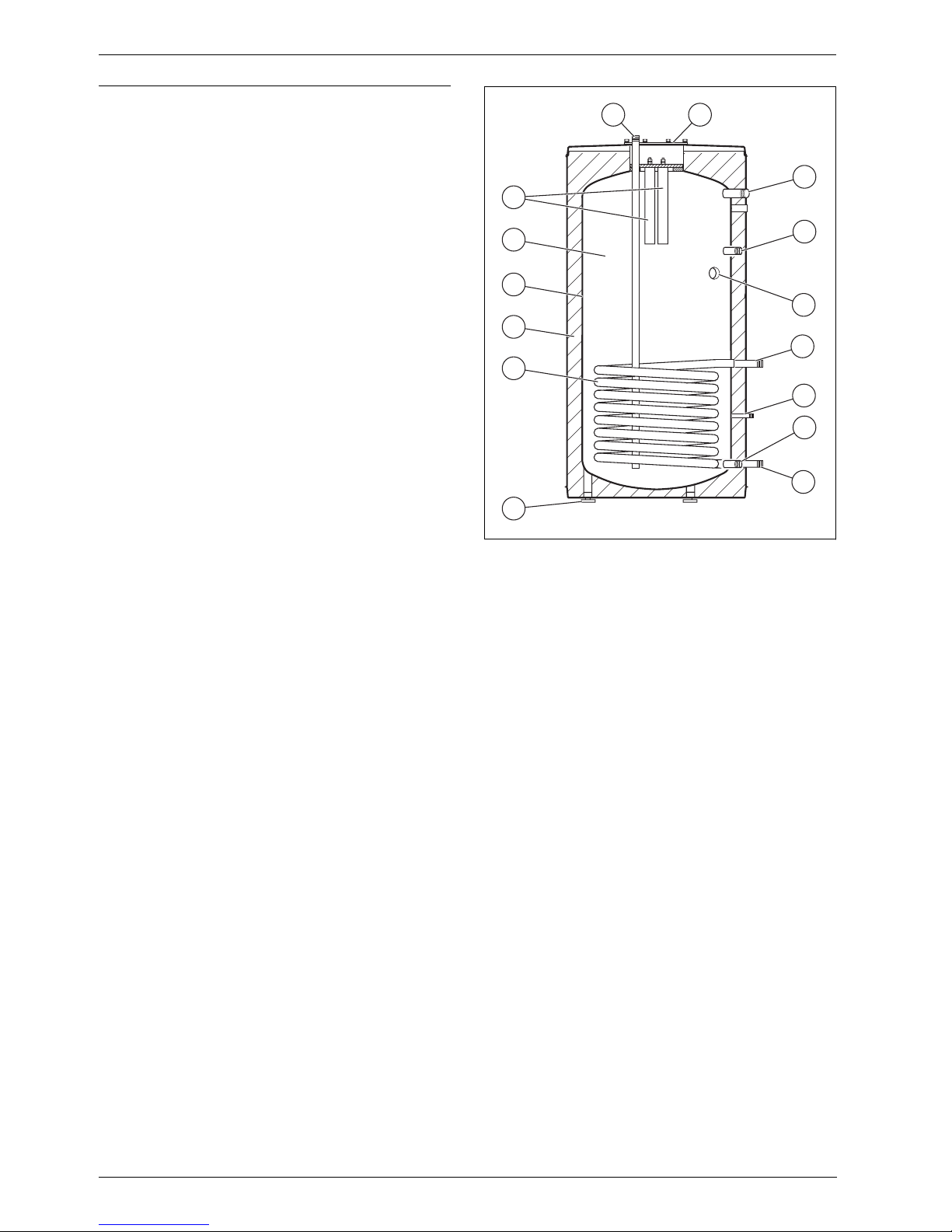
Fig. 1 Sectional view of solar storage tank
[1] Feet for the solar storage tank
[2] Smooth tube heat exchanger (solar thermal system)
[3] Thermal insulation
[4] Thermo glaze
[5] Storage tank
[6] Magnesium anodes
[7] Cold water inlet (EK) and hot water outlet (AW)
[8] Inspection cover
[9] Connection temperature and pressure relief valve (TPR)
[10] Connection DHW recirculation return
[11] Connection electric heating element
[12] Supply from solar thermal system
[13] DHW temperature sensor
[14] Drain valve
[15] Return to solar thermal system
6 720 648 083-01.3ITL
9
10
11
12
13
14
15
4
2.3 Intended use
The solar storage tank is used to heat and store potable water to supply
single- and multi-family homes. Please observe national, regional, and
local codes, regulations, guidelines and standards for potable water.
Heat the solar storage tank only by means of a heat transfer medium
(mixing ratio: heat transfer medium/water max 50/50) and only in
closed systems.
Install the solar storage tank only inside a building. The room must not be
exposed to freezing temperatures and the floor must be level.
Observe the specifications (Æ Chapter 2.8) to ensure proper use.
Any other purpose is considered improper use. Any resulting damage is
excluded from the manufacturer's warranty.
WST50 EL / WST80 EL / WST119 EL – 6 720 648 081 (2012/09)
2.4 Rating plate
The nameplate is located at the lower right on the front of the tank and
contains the following information.
• Model
• Type
• Serial no.
• Contents
• Maximum supply pressure
• Maximum operating pressure
• Maximum hot water operating temperature
• Mixing ratio: heat transfer medium/water
• Maximum operating pressure of solar thermal system
• Maximum heat transfer medium temperature
• Preset value for electric heating element
• Output of electric heating element
• Voltage for electric heating element
• Manufacturer's address
Product description
5 7
6
4
3
8
2
9
2.5 Tools, Materials and Accessories
You need only the standard tools typically used in gas and water
installations to install and maintain the solar storage tank.
A dolly with straps may also be useful.
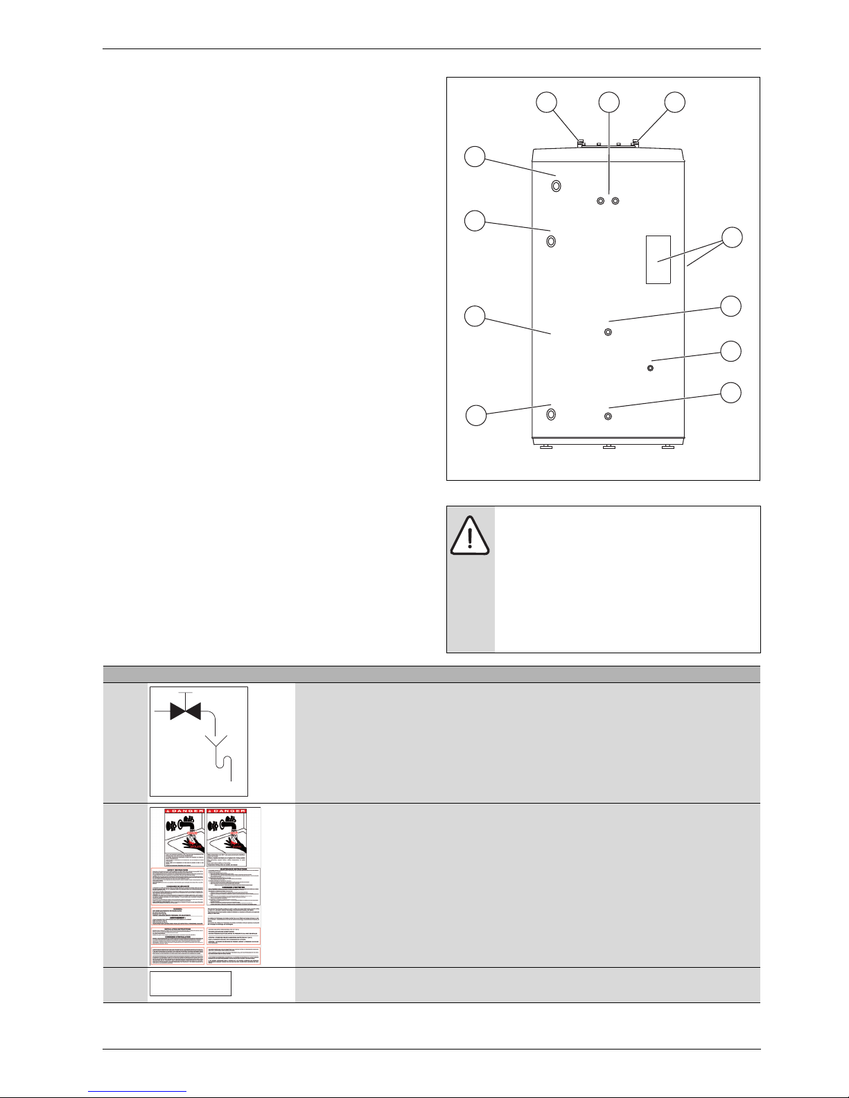
2.6 Symbols and Warnings
The following symbols and warnings are attached to the storage tank.
They refer to their immediate surroundings.
Fig. 2 Symbol and warning locations
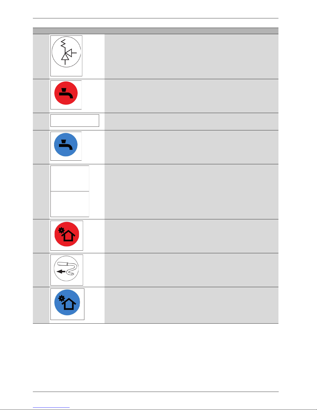
Pos. Symbol/warning Location on the storage tank
1 This symbol identifies the drain valve.
10
11
1
6 720 648 083-26.2ITL
WARNING: Risk of injury from illegible symbols and
warnings!
Labels and signs can become dirty or covered over time.
Dangers can then not be recognized or the necessary
procedures observed. This poses a risk of injury.
B All safety, warning and operating instructions must be
observed at all times and kept in legible condition.
B Damaged signs or labels must be replaced
immediately.
Drain valve
2 The warning label is located on the front of the solar storage tank and contains important information
3 This label is located at the recirculation connection.
Table 3 Symbols and Warnings
WST50 EL / WST80 EL / WST119 EL – 6 720 648 081 (2012/09)
Recirculation
about safe installation, use and maintenance of the storage tank.
5
Product description
Pos. Symbol/warning Location on the storage tank
4 This symbol is located at the temperature and pressure relief valve.
TPR-valve
5 This symbol is located at the upper left on the storage tank, next to the hot water outlet (AW).
Hot water out
6 This label is located at the position where the optional solar pump station is attached.
Optional: Solar station
7 This symbol is located at the upper right on the storage tank, next to the cold water inlet.
Cold water in
8 This warning label is located on the panel covering the electric heating element and on the distribution
Warning
Power supply to the
appliance should be
isolated before
removing this panel
box.
Avertissement
Alimentation de
l'appareil doivent
être isolés avant
de retirer ce panneau
9 This symbol is located at the supply from the solar thermal system.
From collector
10 This symbol is located at the position for the DHW temperature sensor of the solar controller.
Solar sensor
11 This symbol is located at the return to the solar thermal system.
To collector
Table 3 Symbols and Warnings
6
WST50 EL / WST80 EL / WST119 EL – 6 720 648 081 (2012/09)

Product description
2.7 Dimensions and connections
A
205
8"
K
1
K
2
J
I
H
D
1
D
2
C
G
F
E
B
D
6 720 648 083-02.3ITL
Fig. 3 Connections and dimensions: (WST80 EL)
Dimension Unit WST50 EL WST80 EL WST119 EL
ADiameter in (mm) 23.6 (600) 27.6" (700) 29.5" (750)
B Feet for the solar storage tank in (mm) 0.6-2" (15-50) 0.6-2" (15-50) 0.6-2" (15-50)
C Electric heating element in (mm) 26.0" (660) 29.5" (750) 35.7" (908)
DD1 = Drain valve, D2 = Return to solar thermal system in (mm) 4.3" (110) 5.3" (135) 5.4" (138)
E DHW temperature sensor in (mm) 11.8" (300) 19.1" (485) 19.2" (488)
F Supply from solar thermal system in (mm) 16.1" (410) 19.1" (485) 19.2" (488)
G DHW circulation in (mm) 29.3" (745) 33.5" (850) 39.3" (998)
H Attachment location for solar pump station in (mm) 36.6" (930) 41.2" (1046) 52.3" (1328)
I Temperature and pressure relief valve in (mm) 39.4" (1000) 43.9" (1115) 55.0" (1398)
J Height without storage tank feet in (mm) 45.2" (1147) 50.6" (1285) 61.9" (1572)
KK1 = Hot water outlet (AW), K2 = Cold water inlet (EK) in (mm) 45.9" (1166) 51.3" (1304) 62.6" (1590)
Table 4 Dimensions for Fig. 3
K
2.8 Specifications
Performance data Unit WST50 EL WST80 EL WST119 EL
Recommended number of Bosch solar collectors – 1-2 2-3 3-4
Standby heat loss kWh/24 h 1.4 1.8 2.3
Standby heat loss °F/h (°C/h) 0.7 (0.39) 0.6 (0.32) 0.5 (0.27)
Standby capacity when drawing water (first hour supply) Gal (L) 45 (170.3) 57 (215.8) 74 (280.1)
Thermal insulation (R-value, design) °F ft²h/BTU 12.5 - 31.8 12.5 - 31.8 12.5 - 31.8
Thermal insulation (R-value, measured over entire tank surface
area)
Table 5 Performance data
Dimensions and general specifications Unit WST50 EL WST80 EL WST119 EL
Tank capacity Gal (L) 50 (189.3) 80 (302.8) 119 (450.5)
Diameter in (mm) 23.6" (600) 27.6" (700) 29.5" (750)
Height without tank feet
Minimum height of the installation room
1)
2)
Shipping weight lbs (kg) 234 (106) 320 (145) 428 (194)
Empty weight lbs (kg) 187(85) 271 (123) 375 (170)
Standby capacity for electric heating element Gal (L) 20 (76) 32 (121) 48 (180)
Electric heating element voltage V 240 240 240
Table 6 Dimensions and general specifications
WST50 EL / WST80 EL / WST119 EL – 6 720 648 081 (2012/09)
°F ft²h/BTU 12.11 12.31 12.22
in (mm) 45.2" (1147) 50.6" (1285) 61.9" (1572)
in (mm) 78.7" (2000) 78.7" (2000) 78.7" (2000)
7
Product description
Dimensions and general specifications Unit WST50 EL WST80 EL WST119 EL
Electric heating element rating kW 4.5 4.5 4.5
Cold water inlet (EK) Inches NPT m 3/4" NPT m 3/4" NPT m 1"
Hot water outlet (AW) Inches NPT m 3/4" NPT m 3/4" NPT m 1"
Supply to storage tank (solar thermal system) Inches NPT m 3/4" NPT m 3/4" NPT m 3/4"
Return from storage tank (solar thermal system) Inches NPT m 3/4" NPT m 3/4" NPT m 3/4"
Length of solar coil in (m) 338" (8.6) 485" (12.3) 485" (12.3)
Surface area of solar coil ft² (m²) 9.8 (0.9) 14 (1.3) 14 (1.3)
Capacity of solar coil Gal (L) 1.6 (6) 2.2 (8.5) 2.2 (8.5)
Recirculation inlet Inches NPT fm 3/4" NPT fm 3/4" NPT fm 3/4"
Temperature and pressure relief valve Inches NPT fm 3/4" NPT fm 3/4" NPT fm 3/4"
Table 6 Dimensions and general specifications
1) Without storage tank feet.
2) Minimum height of the installation room required for replacement of the magnesium anode.
Permissible maximum values Unit WST50 EL, WST80 EL, WST119 EL
Voltage V 240
Heat transfer medium temperature °F (°C) 275 (135)
DHW temperature °F (°C) 203 (95)
Hot water operating pressure
1)
PSI (bar) 100 (6.89)
Hot water operating temperature PSI (bar) 150 (10.34)
Heat transfer medium operating pressure PSI (bar) 116 (8)
Water connection pressure PSI (bar) 90 (6.2)
Mixing ratio: heat transfer medium/water – 50/50
Table 7 Permissible maximum values
1) With factory-installed temperature and pressure relief valve
Requirements for potable water Unit WST50 EL, WST80 EL, WST119 EL
Water hardness, min. ppm 36
grain/US gallon
°dH
2.1
2
pH value, min. – 6.5
pH value, max. – 9.5
Conductivity, min. S/cm 130
Conductivity, max. S/cm 1500
Table 8 Requirements for potable water
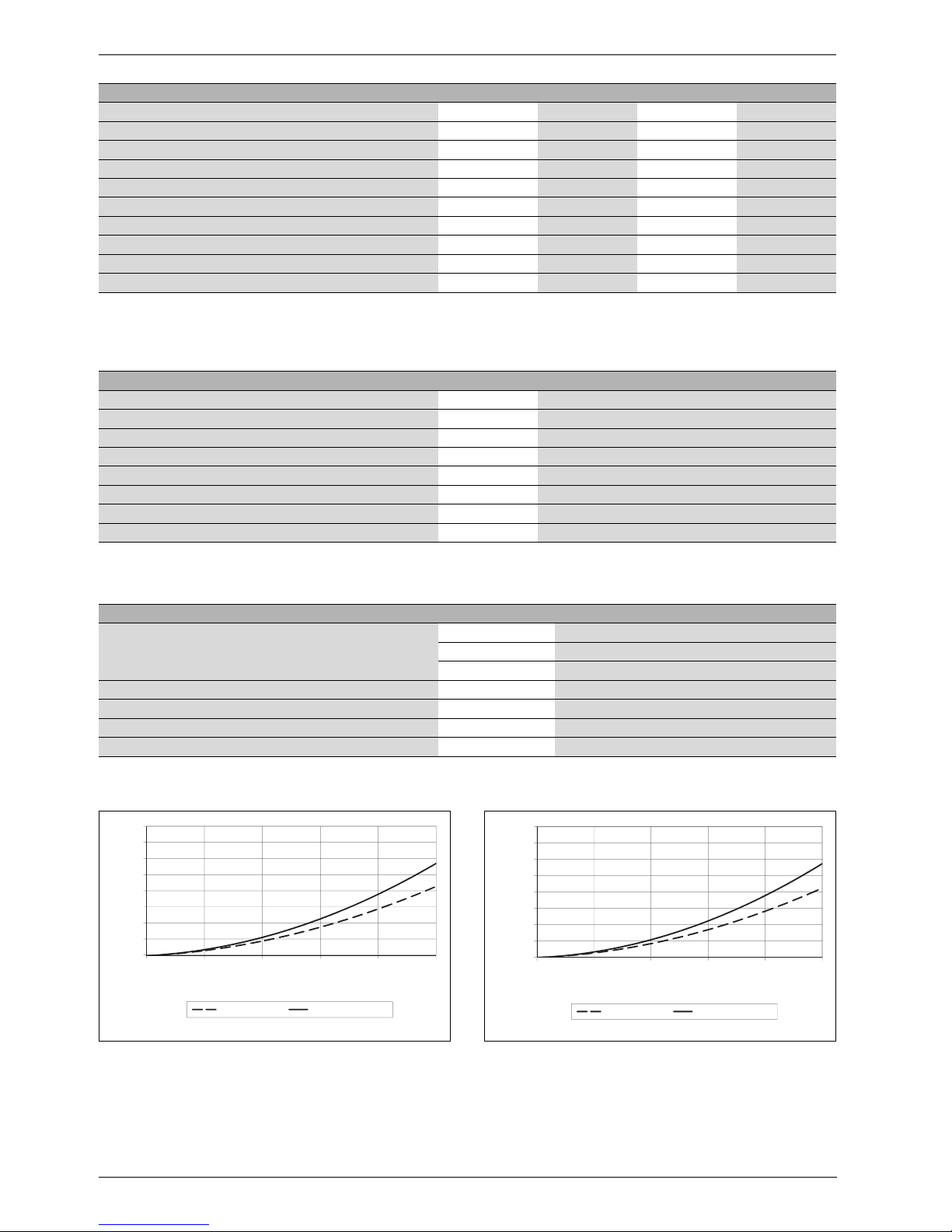
2.9 Pressure Drop Curve
4.0
4,0
3.5
3,5
3.0
3,0
O]
2.5
2,5
2
2.0
2,0
1.5
1,5
1.0
1,0
[feet of H
[feet of head]
0.5
0,5
0.0
0,0
02 46 810
[gal/min]
WST50 EL WST80/119 EL
6 720 648 083-28.1ITL
Fig. 4 Pressure drop curve Fig. 5 Pressure drop curve
200
175
150
125
100
[mbar]
75
50
25
0
01020304050
[l/min]
WST50 EL
WST80/119 EL
6 720 648 083-29.1ITL
8
WST50 EL / WST80 EL / WST119 EL – 6 720 648 081 (2012/09)
Moving the Solar Storage Tank
Model Pressure drop in feet of head (mbar)
2 GPM
(10 l/min)
WST50 EL 0.14 (6.58) 0.44 (20.84) 0.87 (42.11) 1.43 (70.37) 2.13 (105.64)
WST80 EL, WST119 EL 0.17 (8.09) 0.55 (26.81) 1.13 (55.56) 1.89 (94.35) 2.85 (143.19)
Table 9 Pressure drop values
4 GPM
(20 l/min)
6 GPM
(30 l/min)
8 GPM
(40 l/min)
10 GPM
(50 l/min)
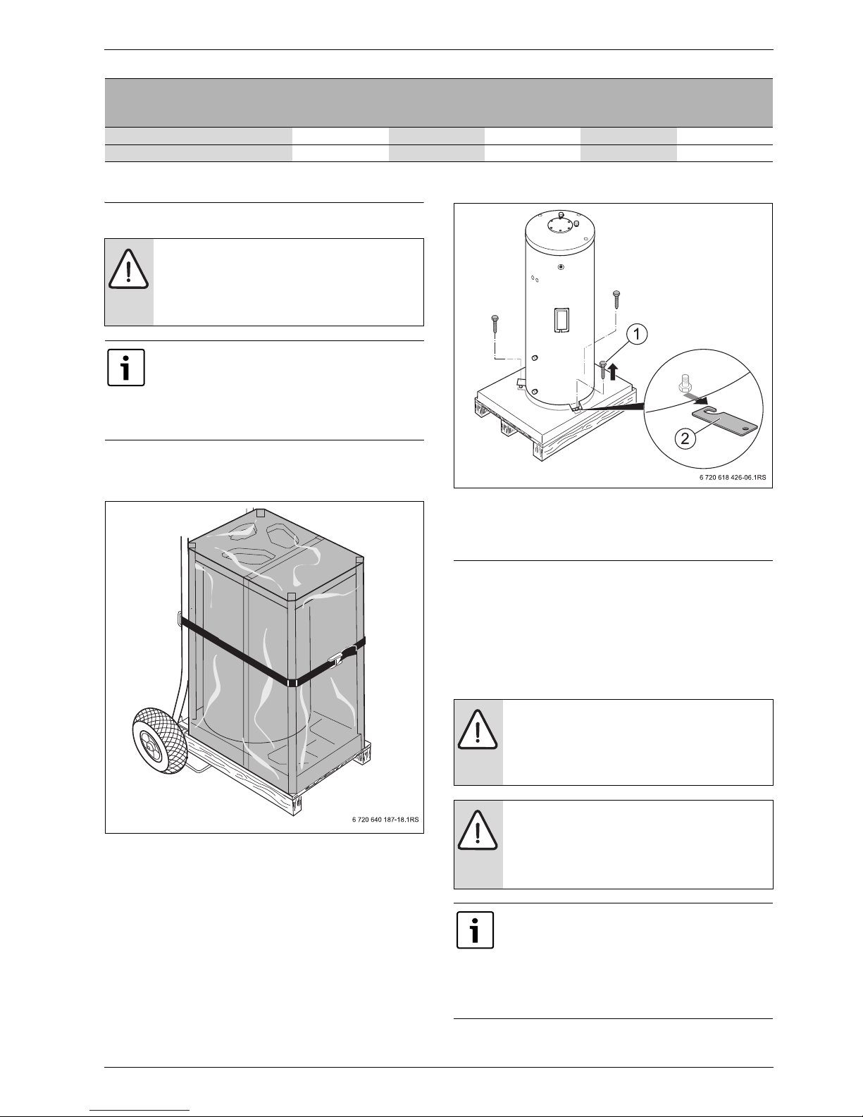
3 Moving the Solar Storage Tank
WARNING: Risk of injury from carrying heavy loads and
inadequately securing loads for transport.
B Use suitable means of transportation, e.g. a dolly with
strap.
B Secure the solar storage tank to prevent slipping.
Where possible, do not remove the tank from its
packaging until it has reached the installation location.
This keeps it protected.
If you are transporting the solar storage tank unpacked,
use a transport net. Protect the connections against
damage.
B Position the dolly at the back of the packed solar storage tank.
B Secure the solar storage tank to the means of transportation with a
strap.
Fig. 6 Securing the solar storage tank for transport
B Transport the solar storage tank to the installation location.
B Remove packaging and dispose of it.
B Remove wood screws [1] from transport bracket [2].
B Unscrew and remove transport bracket.
Fig. 7 Removing the transport brackets
[1] Wood screws
[2] Securing plate
4Installation
The solar storage tank is delivered fully assembled.
B Check that the delivered package(s) are complete and in perfect
condition (Æ Chapter2.1, page 4).
4.1 Solar Storage Tank Installation
4.1.1 Requirements for installation location
NOTICE: Risk of damage from inadequate load-bearing
capacity of the supporting surface or unsuitable
substrate.
B Make sure that the surface on which the solar storage
tank stands has sufficient load-bearing capacity.
NOTICE: Risk of damage from corrosion.
B Install the solar storage tank at a dry location.
B Install this solar storage tank only in closed, unvented
systems.
B Never use open, vented expansion vessels.
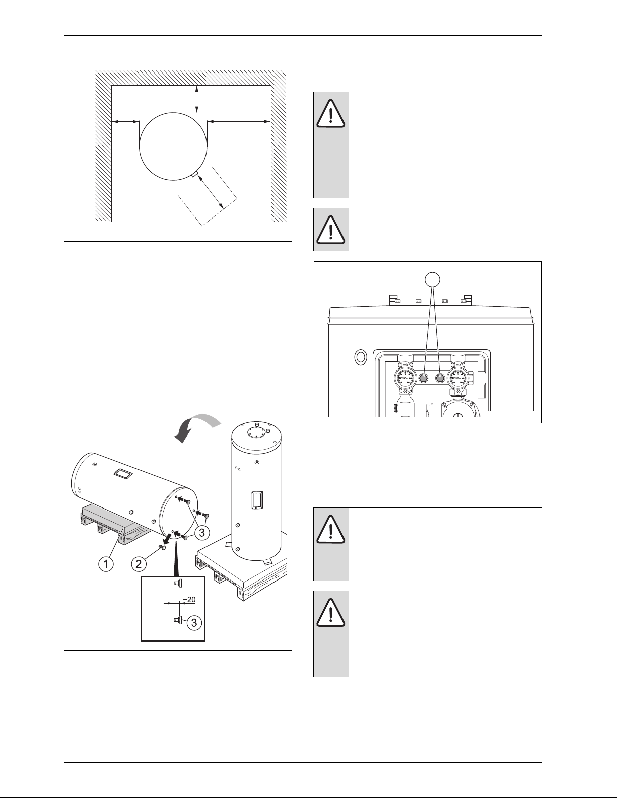
At least 20" (500 mm) clearance above and in front of
the solar storage tank is required for the replacement of
the magnesium anode and the electric heating element
(during maintenance).
B Maintain the minimum height and minimum wall
clearances in the installation room (Æ Tab. 6, page 7
and Fig. 8 ).
WST50 EL / WST80 EL / WST119 EL – 6 720 648 081 (2012/09)
9
Installation
4.2 Attaching the Bosch solar pump station (optional)
To save space, the solar pump station can be attached to the solar
storage tank.
A
A
B
C
6 720 648 083-05.1ITL
Fig. 8 Minimum wall clearances
[A] 2" (50 mm)
[B] 12" (300 mm)
[C] 20" (500 mm)
4.1.2 Positioning the DHW tank
B Lift the solar storage tank from the pallet and position it on a level floor
that has adequate load-bearing capacity.
B Tilt the solar storage tank slowly onto the pallet [1].
B Remove the hex bolts [2].
B Pre-assemble the storage tank feet [3] to approx. 3/4" (20 mm).
B Stand the solar storage tank upright at the installation location and
level it using the feet.
B Maintain minimum wall clearances.
CAUTION: Risk of injury from use of the wrong bolts to
attach the solar pump station.
The bolts of the solar pump station do not match the
threads in the bracket on the solar storage tank. These
bolts can destroy the threads in the bracket, preventing
secure attachment of the solar pump station.
B Use only the bolts included with the solar storage tank
to attach solar pump station
(Æ Chapter 2.1, page 4).
CAUTION: Risk of injury from falling parts.
B Ensure that the solar pump station is secured to
prevent it from dropping while being attached.
1
Fig. 9 Installing the storage tank feet
[1] Suitable surface (e.g. pallet)
[2] Hex-head bolts
[3] Feet of the solar storage tank
6 720 648 083-06.1ITL
6 720 648 083-07.1ITL
Fig. 10 Attaching the solar pump station
[1] Mounting holes
B Use the bolts included with the solar storage tank to attach the solar
pump station.
B Refer to the separate manual for the solar pump station.
4.3 Water connections
DANGER: Risk of fire from soldering and welding!
B Take appropriate protective measures when
soldering and welding as the thermal insulation is
flammable; for example, cover the thermal insulation.
B Check the integrity of the thermal insulation after
completing work.
WARNING: Risk to health from contaminated water!
Work carried out without due care for cleanliness
contaminates the potable water.
B Install and equip the solar storage tank hygienically in
accordance with national standards and guidelines.
B Flush the solar storage tank and pipework thoroughly
with potable water after installation.
10
WST50 EL / WST80 EL / WST119 EL – 6 720 648 081 (2012/09)
Installation
NOTICE: Risk of damage from incorrect connections!
B Use installation material that is heat-resistant to
302 °F (150 °C).
B Use metal connection fittings in water heating
systems with plastic lines.
B When using an electric heating element: Once
installation of the solar storage tank is complete,
inspect the ground conductor (including metal
connection fittings).
4.3.1 Installation example
2 3
AW
TPR
445
EZ
4
EZ
4
1
VS
7
4
EK
6
8
RS
6 720 648 083-03.3ITL
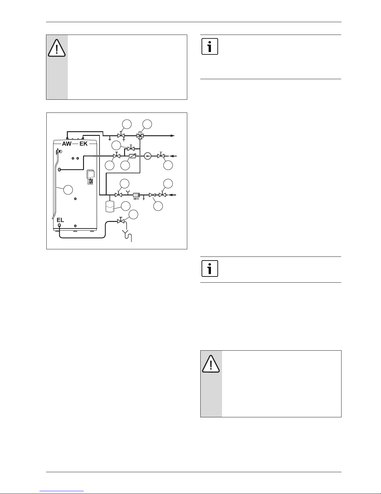
Fig. 11 Recommended piping for potable water
[1 Blow-off line of the pressure and temperature relief valve]
[2] Shut-off and drain valve
[3 Thermostatic DHW mixing valve ]
[4] Shut-off valve
[5] Flow-check valve
[6] Pressure reducer (if required)
[7] Expansion tank
[8] Drain valve (factory-installed)
[AW] Hot water outlet
[EK] Cold water inlet
[EZ] Recirculation inlet
[EL] Drain port
[VS] Supply to storage tank (solar thermal system)
[RS] Return from storage tank (solar thermal system)
[TPR] Temperature and pressure relief valve
Example of typical piping layout for a solar storage tank
Fig. 11 shows typical domestic water piping for a solar storage tank.
The function of the components shown are as follows:
• Shut-off valves (recommended) – Used to isolate the tank for
servicing.
• Flow-check valve (required by some codes) – Used to prevent water
from flowing back out of the tank in the event that inlet water pressure
drops.
• Drain (required) – Used to drain the tank for inspection or servicing.
• Expansion tank (required when a flow-check valve is used) – This
expansion tank absorbs the increased volume caused by heating
water.
Use an expansion tank designed for use on domestic
water systems. Refer to the expansion tank
manufacturer’s literature for the proper size expansion
tank to use.
B If an expansion tank is used, do not install any valves
between the expansion tank and tank inlet.
Domestic Water Piping for Distant Fixtures
In some cases, the furthest fixture may be quite distant from the tank.
Such an installation would result in an unacceptable delay before hot
water reaches these distant fixtures. Even if all the fixtures are relatively
close to the tank, the building owner may want hot water at all fixtures as
soon as they are opened.
A solution to this problem is to run a pipe from the furthest fixture on
each branch back to the recirculation return of the tank (Æ Fig. 11 ).
A small recirculation pump is installed in this line and wired to run
continuously, intermittently, or on demand. A flow-check valve in this
line permits flow only towards the tank inlet.
When no fixtures are drawing water, the recirculation pump moves hot
water from the tank to the end of the branch just below the last fixture,
then back to the inlet of the tank via the return pipe. When a fixture is
opened, hot water is already out in the branch very close to the fixture
and hot water appears at it almost immediately. The flow-check valve
prevents cold water in the tank’s inlet pipe from passing around the tank
and heading directly to the fixture. Because hot water is always
circulating in the hot water branch the entire branch should be insulated
to prevent excessive heat loss.
Anti-scald Valves (Tempering Valves)
Anti-scald valves used with water heaters are also called tempering
valves or mixing valves. An anti-scald valve mixes cold water with the
outgoing hot water to assure that hot water reaching a building fixture is
at a temperature low enough to be safe (Æ Fig. 11 , [3]).
As solar thermal systems can produce high
temperatures, it is strongly recommended and
considered best practice to fit a DHW tempering valve!
Usually, the maximum temperature of the outlet water will stay near the
setting of the tank controller. In some cases, however, hot water usage
patterns can cause the outlet water temperature to rise significantly
above the control setting.
The temperature of water going to the fixtures can be more carefully
controlled through the use of a thermostatic mixing valve. This device
blends a controlled amount of cold water with the hot water leaving the
tank so that water exits the mixing valve at a more constant temperature,
resulting also in increased comfort.
WARNING: Hot water can scald!
An anti-scald mixing valve does not eliminate the risk of
scalding.
B Set the tank thermostat as low as practical.
B Feel water before bathing or showering.
B If anti-scald or anti-chill protection is required, use
devices specifically designed for such purpose. Install
these devices in accordance with their
manufacturer’s instructions.
4.3.2 Pipe connections to the heat source and DHW network
When operated with an external water heater, the electric heating
element must not be connected.
B Use only threaded fittings, with shut-off valves as required, to connect
lines to the tank. Connect tank to piping on site.
WST50 EL / WST80 EL / WST119 EL – 6 720 648 081 (2012/09)
11
Installation
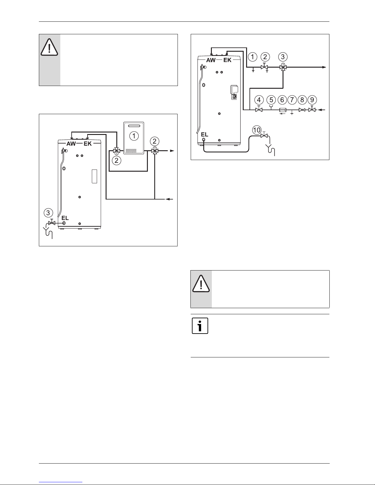
WARNING: Risk of scalding from hot water!
The water temperature can be as high as 194 °F (90 °C)
in solar mode.
B To limit the temperature at the tap to a maximum of
122 °F (50 °C), install a thermostatic hot water mixer
(accessory) in the hot water line (Æ Fig. 12 , [2])
and Fig. 13 , [3]).
B To facilitate debris removal, never install bends in the drain line.
B Install all pipes free of stress.
B Plug all unused tank connections (e.g. recirculation).
6 720 648 083-08.2ITL
Fig. 12 Connection diagram on the DHW side when using an external
water heater
[1] External water heater
[2] Thermostatic DHW mixing valve
[3] Drain valve (factory-installed)
[AW] Hot water outlet
[EK] Cold water inlet
[EL] Port
6 720 648 083-09.1ITL
Fig. 13 Connection diagram on the DHW side when using the internal
electric heating element (no external water heater)
[1] Air bleeder valve
[2] Shut-off and drain valve
[3] Thermostatic DHW mixing valve
[4] Shut-off valve
[5] Pressure gauge connection (optional)
[6] Flow-check valve
[7] Purge valve
[8] Pressure reducer (if required)
[9] Shut-off valve
[10] Drain valve (factory-installed)
[AW] Hot water outlet
[EK] Cold water inlet
[EL] Port
4.3.3 Temperature and Pressure Relief Valve (TPR) Blow-off Line
WARNING: Improper placement and piping of the TPR
valve can cause severe personal injury, death or
substantial property damage.
B Do not install any valve between the TPR valve and the
tank connection or on the TPR valve blow-off line.
12
The TPR valve is not intended for constant duty, such as
relief of pressure due to repeated normal system
expansion. Correct this condition in a domestic hot
water system by installing a properly sized expansion
tank. Refer to the expansion tank manufacturer’s
installation instructions for proper sizing.
The temperature and pressure relief valve (TPR) blow-off line must
be:
• Made of material capable of withstanding a temperature of 250 °F
(121 °C) or higher
• Directed so that hot water flows away from all persons
• Directed to a suitable place for drainage.
• Installed so as to allow complete draining of the temperature and
pressure relief valve (TPR) and blow-off line.
• Terminated no more than 6" (150 mm) above the floor or as required
by code (Æ Fig. 14 , [X]).
WST50 EL / WST80 EL / WST119 EL – 6 720 648 081 (2012/09)
 Loading...