

Page 1
TheatreCue
User Manual
Cueing and Presentation Control Specialists
Page 2

Contents
Introduction 3
Safety Instructions 4
Setting Up 5
Operating Instructions 7
Programming Outstations 7
Main Unit Setup 9
Giving Cues 10
Testing and Faults 12
Certificate of Conformity 14
Environmental 15
Technical Support Contact 15
2
Page 3

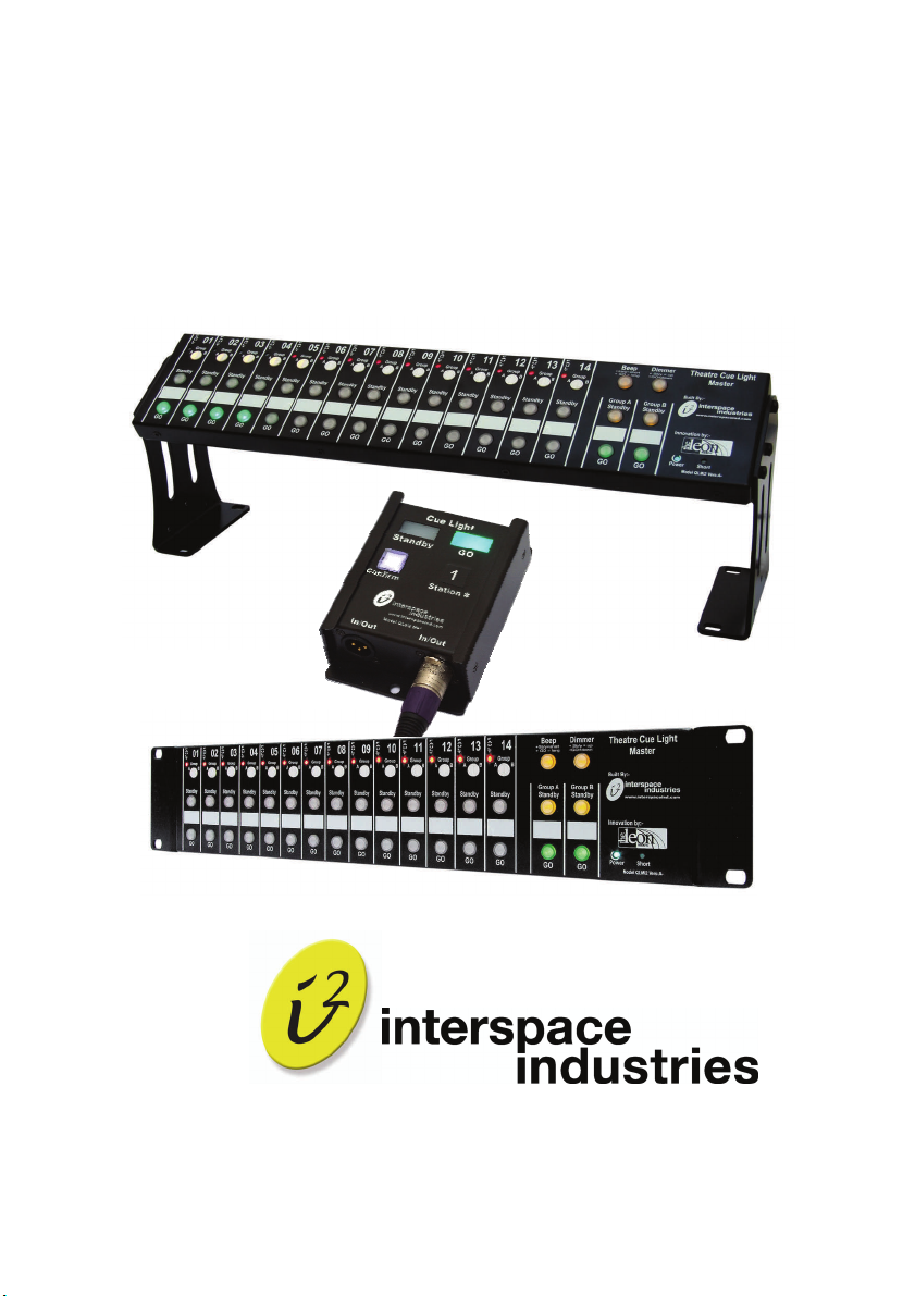
Introduction
TheatreCue provides for cueing of remote Outstations, each acting as an
interactive cuelight or as a direct controller of stage equipment. Each Main
Unit controls up to 14 Outstations and the system is designed so that up to
8 Main Units can be linked, thus providing for the control of up to 112
Outstations if required. The system is easily set up using standard XLR
(mic) cables and allows for any combination of daisy chain, star or looping
configuration.
System operators are able to quickly set-up and assign remote stations in
any preferred order, and to either of two groups for the easy simultaneous
cueing of multiple actions. Stage managers are then able to give ‘standby’
commands, which Outstation operators are able to confirm prior to the
stage manager giving the ‘go’ command. TheatreCue can be RS232
computer controlled and features numerous continuous system fault alert
functions; for the fast diagnosis of any cabling or system failures.
Simple, Effective Live Event Cueing
We hope that TheatreCue
feedback that you have about this or any of our products.
Thank you.
The Interspace Industries Team
www.interspaceind.com
exceeds your expectations and welcome any
3
Page 4

Safety Instructions
All safety and operating instructions should be read before this product is
operated and should be retained for further reference. Please adhere to
all the warnings on this product and in these operating instructions. Please
follow these instructions carefully.
Power. Only use the power source indicated on the device. Devices
equipped with a grounded plug should only be used with a grounded type
outlet. In no way should this grounding be disconnected, modified or
suppressed.
Power Supply Lead. To unplug the device always pull by the plug itself,
not the power supply lead. The power source outlet should always be near
the TheatreCue Main Unit and easily accessible. Ensure the power supply
lead cannot be walked on or damaged by items placed on or against it. Do
not use if the power supply lead is damaged. Using the device with a
damaged power supply lead may expose you to electric shock or other
hazards. Check the condition of the power supply lead regularly. Contact
your dealer or service centre immediately for a replacement if damaged.
Keep Away From Harmful Substances
To prevent the risk of electric shock and fire, do not expose this device to
rain, humidity or intense heat sources (such as radiators or direct
sunlight). Avoid using this equipment in environments where there is
excessive heat, dust, moisture, chemicals, vibration or mechanical
shocks.
Slots and Openings. These are designed into the device for ventilation
and to avoid overheating. Always ensure these openings remain clear. Do
not attempt to insert anything into these openings under any
circumstances. If liquids have been spilled on, or objects have fallen into
the product it must be checked by a qualified technician before re-using.
Connections. All inputs and outputs (except for power input) are TBTS
defined under EN60950.
4
Page 5
• DO NOT OPEN SYSTEM DUE TO HIGH VOLTAGE.
• DO NOT IMMERSE IN WATER.
If you have any queries regarding these safety instructions or how to
maintain the unit please do not hesitate to contact us on:
+44 (0) 870 770 8088
Servicing. Do not attempt to service this product yourself. Opening or
removing covers and screws may expose you to electric shocks or other
hazards. Refer all servicing to qualified service personnel.
Setting Up
Figure 1 Connections Diagram
5
Page 6

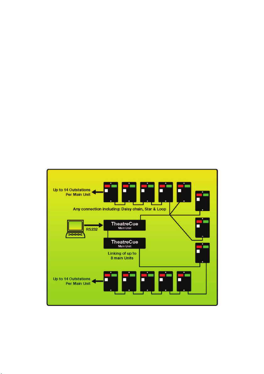
Figure 2 Linking Main Units
All connections to Outstations can be made using standard 3-pin XLR
(mic) cables. TheatreCue
can be set up and operated over a combined
total distance of up to 1000 metres (3000ft) when using the highest possible quality cable. 14 Outstations per Main Unit can be connected in any
combination of star, daisy-chain or loop configuration. The loop configuration allows the whole system to keep working even when a break in the
cable exists.
Up to 8 Main Units can be linked also, providing for control of up to 112
Outstations if required (refer figure 2).
Cuelight Outstations function as interactive visual cue signals (where talent or crew can ‘confirm’ standby signals). The beeper type Outstation
provides for audible cue signals as well as the interactive cuelight functionality, and relay-type Outstations can directly control electrical equip-
6
Page 7

ment. Relay-type Outstations are rated up to 1A, 48V and are NOT DESIGNED FOR MAINS SWITCHING.
The Main Units can be controlled by computer via the RS232 interface
also.
Unpacking and Connections. Unpack the Main Unit and place on a flat
surface within easy reach of the operator. Set up the preferred mounting of
the Main Unit by removing the bracket securing screws on each side of the
Main Unit and repositioning each bracket for either 19” 2RU rack mounting
or freestanding, and then replace and tighten the bracket securing screws.
Mount the Main Unit in the rack unit if this is the preferred mounting configuration.
If multiple Main Units are being used and linked, mount these also and
connect to each other using the RS232 (serial) connectors (loop output
from Main Unit one to input of Main Unit two etc).
Unpack the Outstations and install where required. Connect these to the
Main Unit using high quality, standard 3 pin XLR (mic) cables (refer fig 1
for connection options).
Apply power to the Main Unit/s using the 12V DC power adaptor/s provided and switch on the mains power. All LEDs in the system illuminate
briefly to confirm that all are operational. The system is now ready for programming or operation.
Operating Instructions
Programming Outstations
1. With the system fully powered up, unplug the XLR input cable
which is providing power to the Outstation and wait 10 seconds for
the Outstation to fully power down (i.e. until all LED lamps on the
Outstation are fully extinguished).
2. While holding down the ‘Confirm’ button, reconnect power to the
Outstation. Release the ‘Confirm’ button and the ‘Standby’ light will
flash to confirm the Outstation is now in programme mode
7
Page 8

3. Press the ‘Confirm’ button as many times as the number you want
to assign to this Outstation. For example; to programme the Outstation to be number 11, press the ‘Confirm’ button 11 times. If
you want to programme the Outstation to be number 6, press the
‘Confirm’ button only 6 times. The ‘Standby’ light will then confirm
your programming by flashing the same number times.
4. If the Outstation has been programmed correctly, you can simply
leave it and move to the next Outstation (whereupon after 30 seconds the ‘Standby’ LED will stop flashing and the Outstation will
then remain programmed accordingly), or press and hold the
’Confirm’ button to re-boot the Outstation, or you can disconnect
the power cable (as in 1. above), wait for the Outstation to fully
power down, then reconnect. The Outstation will then be programmed to the new assigned number and the Main Unit will be
updated immediately.
5. If when the Outstation confirms the programming the number is
incorrect and you need to change the number it is programmed to,
simply press the ‘Confirm’ button the required number of times
again and check the number of replayed flashes once more. When
correct, perform the confirmation by following the steps in 4.
above.
Dimming of Outstations
To dim the LEDs on Outstations, hold down the ‘Dimmer’ button on the
Main Unit and press the ‘Standby’ button on the channel assigned to the
Outstation in question. Each press of the ‘Standby’ button dims the LEDs
on the Outstation by 20%. When the illumination level is correct, simply
release all buttons on the Main Unit and the dimming programming is complete. This process needs to be repeated for each additional Outstation
requiring dimming also.
IMPORTANT NOTE:
When enabled, the ‘Dimmer’ button
is also a master reset of all cues!
If any cues have already been given (i.e. Standby, Confirmed and/or Go),
these will be cancelled instantly whenever the ‘Dimmer’ button is pressed.
8
Page 9

Main Unit Setup
To enter the Main Unit setup mode, press and hold all 3 buttons of channel 1 while turning on the mains power. When all setup programming has
been completed, press the ‘Group B Go’ button to exit and save changes.
Set Main Unit Address.
The current Main Unit address is displayed using the fault LEDs of channels 1 to 8. If address #5 is programmed, then fault LED #5 will be on.
Change the address by pressing the ‘Dimmer’ button. Valid addresses are
1 to 8. Unless the RS232 adaptor unit is used, the address can be set to
any value. Factory default address is #1
Calls from Outstations.
The ability for the Main Unit to receive calls from Outstations can be
turned off or on (i.e. when the ‘Confirm’ button is pressed at any Outstation, the ‘Standby’ and ’Go’ buttons assigned to that Outstation will flash
on the Main Unit . When the Main Unit is in setup mode, the status of this
function is displayed by the channel 2 ‘Go’ button. The factory default =
LED on (enabled). Use the channel 2 ‘Go’ button to toggle this on and off.
Enable/disable the Beep Button.
When the Main Unit is in setup mode, the status of this function is displayed by the channel 3 ‘Go’ button. The factory default = LED on
(enabled). Use the channel 3 ‘Go’ Button to toggle this on and off.
Link/unlink the Master Group A and B Buttons.
The Master Group buttons are normally linked between multiple Main
Units. When the RS232 Interface Unit is connected, it may be desirable to
have the Main Units not linked. This option is only possible when the
RS232 Interface Unit is connected. When the Main Unit is in setup mode,
the current status of this function is displayed by the channel 4 ‘Go’ button.
The factory default = LED on (linking enabled). Use the channel 4 ‘Go’
Button to toggle this on and off.
9
Page 10

Giving Cues
Standby, Confirm, Go.
To send a ‘Standby’ cue to an Outstation, the Main Unit operator presses
the ‘Standby’ button for the required Outstation. Once the standby cue has
been given, both the ‘Standby’ button on the Main Unit and the ‘Standby’
LED on the Outstation will flash continuously. Once given, the standby cue
can be cancelled at any time by the Main Unit operator simply by pressing
the ‘Standby’ button again.
Cast or crew can confirm they have received the standby cue if required
by pressing the ‘Confirm’ button on the Outstation. This is not mandatory
however as the go cue can still be given without the standby cue being
confirmed. Once confirmed, both the ‘Standby’ LED on the Outstation and
the ‘Standby’ button on the Main Unit will remain lit continuously.
When required, the Main Unit operator can signal a ‘Go’ cue by pressing
the ‘Go’ button for the required Outstation. Once a Go cue is given, the
Outstation ‘Standby‘ LED and Main Unit buttons will be extinguished and
both the green ‘Go’ LED on the Outstation and the ‘Go’ button on the Main
Unit will remain lit continuously for 5-6 seconds, then flash for 10-14 seconds and then the Go cue expires. This gives a combined Go cue duration
of at least 15 seconds. If the cue hasn’t been acted on by then, it is certain
to be too late but the Main Unit operator can repeat the Go cue by pressing the ’Go’ button again once the cue has expired, as many times as they
need to. A Go cue can be cancelled anytime before the cue expires by
pressing the ‘Go’ button again.
Grouping.
Any or all of the TheatreCue channels can be assigned to the group master ‘Go’ and ‘Standby’ buttons A and B. The group assignment for any
channel is controlled by the dual LED ‘Group A B’ button on the Main Unit.
Pressing any of the channel ‘Group A B’ buttons cycles through the four
possible group assignments: A, B, A+B and none.
Once each required channel has been assigned to either of the A, B or
A+B groups, these channels can all be controlled simultaneously using
10
Page 11

just the Group A and B master ‘Go’ or ‘Standby’ buttons. All group assigning remains stored in memory, even during power down. The assignments
will therefore be restored whenever the Main Unit is powered up again and
remain active until reassigned.
Any channels not assigned to either Group A, B, or A+B will still need to
be controlled as individual channels. Any channels that have been assigned to Group A, B, or A+B can still be manually controlled at any time if
required also.
When multiple Main Units are linked via the RS232 ports, the system can
be programmed to also link the group master buttons. In this configuration,
pressing any of the ‘Go’ or ‘Standby’ group master buttons on any Main
Unit will simultaneously cue all assigned channels on all Main Units accordingly. Up to 8 Main Units can be linked for larger systems providing for
up to 112 Outstations. See ‘Main Unit Setup’ for more information on linking Main Units.
Using the Beeper.
The Main Unit operator can give audible cues to beeper-type Outstations.
When the operator holds down the ‘Beep’ button on the Main Unit and
simultaneously presses the ’Standby’ button on the channel assigned to
the required beeper-type Outstation, the Outstation will emit a discrete
“click” sound (a very short beep). By pressing both the ‘Beep’ and ‘Go’
buttons, the Outstation sounds a long beep for as long as the button is
pressed - up to a maximum of two seconds. The ’Standby’ LED on the
cued Outstation flashes also while the beeper operates. Beeper-type Outstations function just like standard cuelight Outstations when not giving
audible cues.
The Beep button can also be used in conjunction with the group master
buttons to give audible cues to groups of beeper-type Outstations.
The beep button can be disabled on the Main Unit. See “Main Unit Setup”
for details.
11
Page 12

Testing and Faults
Positive Monitoring.
TheatreCue has been designed to continuously check for, and signal, any
possible fault condition. This means that operators are provided with the
maximum possible advance warning if there is any risk that a cue cannot
be given. As an example, all feedback given by the Main Unit is driven
entirely by the Outstations themselves. The ‘Standby’ and ‘Go’ buttons on
the Main Unit therefore will not illuminate unless the respective Outstation
has signalled to the Main Unit to do so. This ensures that not only complete cable or Outstation failures can be detected instantly but intermittent
or ‘noisy’ circuits likely to impair the optimum performance of TheatreCue
will be detected and the operator alerted.
Fault LED.
The fault LED on each channel of the Main Unit can be in either of 3
states; ON (continuously), OFF or FLASHING. If all connections and system functions are normal, the fault LED will remain OFF. If there has never
been an Outstation connected to that channel since initial power up, the
fault LED will remain ON continuously. If no signal can be received from
an Outstation, there is an intermittent or ‘noisy’ connection or an Outstation has been unplugged, the fault LED will FLASH. Once the source of
the fault has been identified and rectified, power down the Main Unit, wait
10 seconds then power it up again. Test the channel again by sending
several cues to the Outstation. If the fault LED remains OFF, the fault has
been cleared. If it remains ON continuously, the Outstation has become
completely disconnected. If it is still flashing, a fault still exists.
Short LED.
If there is a short circuit anywhere on the Outstation circuit; power is removed from all Outstations, the system will commence testing at between
2 and 8 second intervals to see if the short has been cleared and the
‘Short’ LED will illuminate continuously. Whilst in this state, all cabling and
connections can be checked ‘live’ to see when the fault clears and the
‘Short’ LED goes out.
12
Page 13

System Lamp Test.
The Main Unit conducts a short lamp test on start up but a lamp test of the
entire system (including Outstations) can be carried out during set up and
prior to the commencement of the event if required. With the system powered up, hold down the ‘Dimmer’ Group B, ‘Standby’ and ‘Go’ buttons all
together until all the Main Unit LEDs illuminate. Release the buttons and
the Main Unit LEDs will now flash slowly across all channels. The red
‘Short’ LED will flash also and the power LED will remain illuminated constantly. This test will verify that all LEDs are functioning properly. Whilst in
this mode, all LEDs and lamps on all Outstations will flash also so each
can be checked for full functionality. To cancel lamp test mode, hold down
the ‘Dimmer’ Group B, ‘Standby’ and ‘Go’ buttons all together again or
power down the Main Unit.
Individual Outstation Lamp Test.
To lamp test any Outstation, disconnect the power input XLR cable from
the Outstation, wait 10 seconds for the Outstation to fully power down,
then reconnect the power again. The Outstation performs a short lamp test
whenever it is powered up.
Diagnostic Mode.
This mode allows the operation of the LEDs and data communications to
be verified. Enter the diagnostic mode by pressing both of the Group B
‘Standby’ and ‘Go’ buttons for approximately 4 seconds, until all LEDs on
the Main Unit illuminate. Release the buttons and the ‘Go’ and ‘Standby’
LEDs on all Outstations flash alternately. Any ‘Fault’ LEDs illuminating
briefly is an indication of data communication errors. The usual causes for
this are excessive cable lengths and/or too many Outstations at the end
of a long cable run. Exit the Diagnostic Mode by pressing either of the
Group B ‘Standby’ or ‘Go’ buttons ,or by powering down the Main Unit.
13
Page 14

DECLARATION OF CONFORMITY
We (Interspace Industries 28 High Street, Arlesey, Bedfordshire SG15 6RA , UK) declare
under our sole responsibility that the products:
TheatreCue
(Part Nos: CUERACK14, CUEOUT, CUERELAY, CUEBEEP, CUE232)
Conform to the following standards:
EN60950-1:2002,
BS EN 55103-1:1997
BS EN 55103-2:1997
Following the provision of:
The Low Voltage Directive 73/23/EEC and
The Electromagnetic Compatibility Directive 89/336/EEC
Issued on: 25th January 2008
Dave Humphrys,
Managing Director, Interspace Industries
14
Page 15

WEEE and RoHS Compliance. TheatreCue and its associated
accessories have been manufactured and sold in accordance with the
requirements of the EC WEEE and RoHS directives. Please return all endof-life items to your supplier, or your local Interspace Industries
representative directly, for appropriate disposal.
Packaging Materials:
Cardboard box: Grade 150 K/T ‘B’ (Single Walled Corrugated - Brown
Kraft)
Protective Foam: Grade HLB 22 Grey Foam (High Load Bearing)
Equipment Supplied
• 1 x TheatreCue Main Unit
• Outstations to order
• 12v DC power supply
Available Accessories
• Additional TheatreCue Main Units
• Additional Cuelight Outstations
• Relay-type Outstations
• Beeper-type Outstations
• RS232 Adaptor
For Technical Support or Sales Enquiries:
Interspace Industries Head Office:
+44 (0) 870 770 8088
Emergency Technical Support Hot Line:
+44 (0) 7976 385 046
Website:
www.interspaceind.com
Environmental
15
Page 16

28 High Street
Arlesey
Bedfordshire
SG15 6RA
UK
Tel: +44 (0) 870 770 8088
Fax: +44 (0) 870 770 8089
Email: moreinfo@interspaceind.com
www.interspaceind.com
16
 Loading...