

Page 1
8
Unit 1A
126 Great North Road
Hatfield, Hertfordshire
AL9 5JN
United Kingdom
Tel: +44 (0) 1462 600101
Email: moreinfo@interspaceind.com
www.interspaceind.com
Indicator
2
User Manual
Cueing and Presentation Control Specialists
Page 2

2
Contents:
Introduction 3
Safety Instructions 4
Diagrams 5
Regulations Compliance CE 5
Regulations Compliance FCC 6
Operating Instructions 6
Front Panel Button Dimming 7
Equipment Supplied 7
Technical Support Contact 7
7
While any of the colours have been selected, the FLASH button can be pressed momentarily
and the display lamp will flash on and off. The selected colour button on the front panel will
also flash. Pressing the FLASH button again will stop the display lamp from flashing and it
will remain illuminated.
At any time while the display lamps are flashing, an alternative colour can be selected by
simply (momentarily) pressing a different coloured button on the front panel of the main unit
and the display lamp will change to that colour and remain flashing also.
To completely extinguish the display lamps while they are flashing, simply press the colour
select button that is also flashing on the front panel and the display lamps will be
extinguished. The FLASH button on the front panel will remain flashing and this can be
pressed again to de-activate the flash mode if required.
Front Panel Button Dimming. The buttons on the front panel of the main unit can be
dimmed if required for low- light level control environments.
While pressing and holding the FLASH button on the front panel of the main unit,
momentarily press the GREEN colour select button. Continue to hold down the FLASH
button and all buttons will flash once to confirm the system is in dimming mode. While still
holding down the FLASH button, momentarily press the GREEN colour select button to
adjust the dimness of the front panel control buttons. Once the required dimness setting is
achieved, release the FLASH button to take the system out of dimming mode.
Dimness can be adjusted while the system is operating if required without any change to the
display lamps status and the dimness setting will remain until changed again - including
during power off.
Equipment Supplied
Indicator Main Station
2 x CombiLamps
IEC power lead
Note: User supplied 3-pin XLR (mic) cables are required to connect
display lamps to the main unit.
For Technical Support or Sales Enquiries
Interspace Industries Head Office:
+44 (0) 1462 600101
Emergency Technical Support Hot Line:
+44 (0) 7976 385046
Website:
www.interspaceind.com
Page 3

6
Environmental
WEEE and RoHS Compliance. Indicator2 and its associated accessories have been manu-
factured and sold in accordance with the requirements of the EC WEEE and RoHS directives. Please return all end-of-life items to your supplier, or Interspace Industries directly, for
appropriate disposal.
Packaging Materials:
Cardboard box: Grade 150 K/T ‘B’ (Single Walled Corrugated - Brown Kraft)
Protective Foam: Grade HLB 22 Grey Foam (High Load Bearing)
FCC
NOTE: This equipment has been tested and found to comply with the limits for a Class B
digital device, pursuant to Part 15 of the FCC Rules. These limits are designed to
provide reasonable protection against harmful interference in a residential installation.
This equipment generates, uses and can radiate radio frequency energy and, if not
installed and used in accordance with the instructions, may cause harmful interference
to radio communications. However, there is no guarantee that interference will not
occur in a particular installation. If this equipment does cause harmful interference to
radio or television reception, which can be determined by turning the equipment off and
on, the user is encouraged to try to correct the interference by one or more of the
following measures:
-- Reorient or relocate the receiving antenna.
-- Increase the separation between the equipment and receiver.
-- Connect the equipment into an outlet on a circuit different from that to which the receiver is connected.
-- Consult the dealer or an experienced radio/TV technician for help
Operating Instructions
Unpacking and Connections. Unpack the main unit and place on a flat surface within easy
access for the Operator (see Fig 1). Adjust the angle of the main unit by loosening the
bracket securing fasteners on each side of the main unit and re-tightening once the most
comfortable angle is achieved.
Position each display lamp for best viewing and connect them to the main unit using 3-pin
XLR (mic) cables. Typical operating distances can be as much as 100m (300ft).
Note: Additional lamps (up to 2 per output) can be added to the system using standard mic
cable splitters (3-pin XLR type), thereby providing multiple displays located on more than one
lectern for example. The sum of the total distance between all displays and the main unit
should not exceed 100m (300ft) however.
Connect the IEC power cable to Indicator
2
and switch on the power at the source.
Basic Operation. Momentarily pressing any of the coloured buttons on the front panel of the
Indicator2 will cause the display lamps to illuminate in that colour. The lamp will remain illumi-
nated in that colour until either the same button is pressed again (this turns off the display
lamp), or, an alternative coloured button is pressed on the front panel of the main unit.
3
Introduction
Indicator2 is the AV professional’s best friend when it comes to controlling
a live event. Signalling to presenters or crew to ensure everything runs to
time is the key to a smooth, professional show and Indicator2 is a simple
and effective ‘Traffic Light’ system.
Using everyone’s understanding of Green, Amber and Red signals,
Indicator2 silently prompts presenters when to speak (green light), when to
summarise (amber light) and when to finish (red light). The main control
unit has dual indicator power outputs so that two lamps can be located for
easy viewing, or to cue more than one presenter or crew at the same time.
The indicator display lamps are self-contained and are connected using
standard 3-core XLR (mic) cables. Operation is by the main unit front
panel. Cable lengths can be in excess of 100metres (300 ft).
Live Event Timekeeping Made Simple!
We hope Indicator2 exceeds your expectations and welcome any
feedback that you have about this or any of our products.
Thank you.
The Interspace Industries Team
www.interspaceind.com
Page 4

4
Safety Instructions
All safety and operating instructions should be read before this product is operated and
should be retained for further reference. Please adhere to all the warnings on this product
and in these operating instructions. Please follow these instructions carefully.
Power. Only use the power source indicated on the device. Devices equipped with a
grounded plug should only be used with a grounded type outlet. In no way should this
grounding be disconnected, modified or suppressed.
Power Supply Lead. To unplug the device always pull by the plug itself, not the power
supply lead. The power source outlet should always be near the Indicator2 main unit and
easily accessible. Ensure the power supply lead cannot be walked on or damaged by items
placed on or against it. Do not use if the power supply lead is damaged. Using the device
with a damaged power supply lead may expose you to electric shock or other hazards.
Check the condition of the power supply lead regularly. Contact your dealer or service centre
immediately for a replacement if damaged.
Keep Away From Harmful Substances
To prevent the risk of electric shock and fire, do not expose this device to rain, humidity or
intense heat sources (such as radiators or direct sunlight). Avoid using this equipment in
environments where there is excessive heat, dust, moisture, chemicals, vibration or
mechanical shocks.
Slots and Openings. These are designed into the device for ventilation and to avoid
overheating. Always ensure these openings remain clear. Do not attempt to insert
anything into these openings under any circumstances. If liquids have been spilled on,
or objects have fallen into the product it must be checked by a qualified technician before reusing.
Connections. All inputs and outputs (except for power input) are TBTS defined under
EN60950.
DO NOT OPEN SYSTEM DUE TO HIGH VOLTAGE.
DO NOT IMMERSE IN WATER.
If you have any queries regarding these safety instructions or how to maintain the unit please
do not hesitate to contact us on:
+44(0)1462 600101
Servicing. Do not attempt to service this product yourself. Should an unauthorised person
attempt to either open the covers or service our products, it may invalidate your Limited
Factory Warranty. In addition, opening or removing covers and screws may expose you to
electric shocks or other hazards. Refer all servicing to qualified service personnel.
5
Diagram
DECLARATION OF CONFORMITY
We declare under our sole responsibility that the product
Indicator2
Conform to the following standards:
EN60950-1:2006/A1:2010
BS EN 61000-6-3:2007
BS EN 61000-6-1:2007
Following the provision of:
The Low Voltage Directive 73/23/EEC and
The Electromagnetic Compatibility Directive 89/336/EEC
Date: May 2011
Dave Humphrys
Managing Director, Interspace Industries Ltd
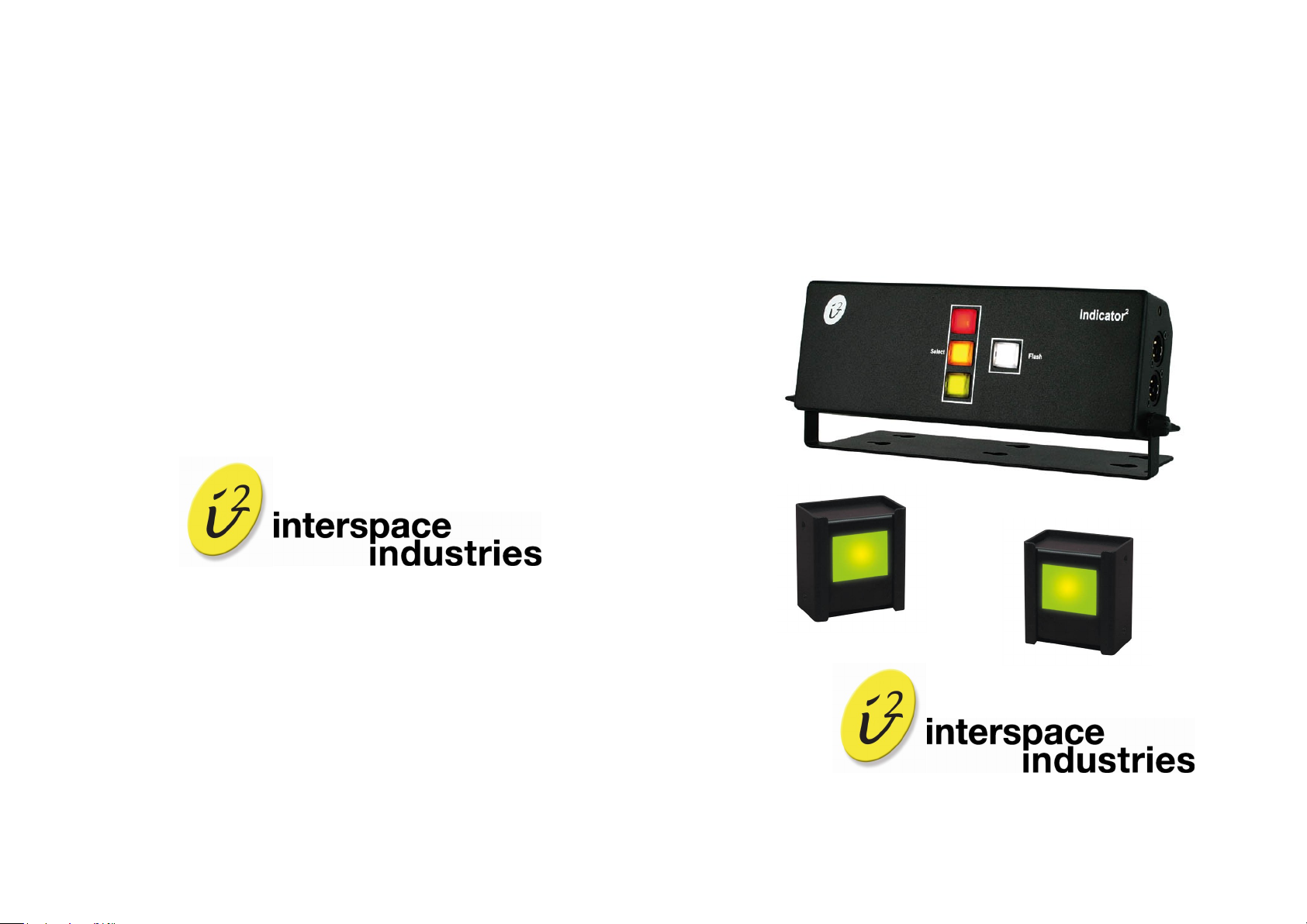
Figure 1: Indicator
2
Connections Diagram
 Loading...