

Page 1
Application Note 1404
ISL88731EVAL2Z and ISL88731CEVAL2Z Evaluation
Boards Setup Procedure
Introduction
The ISL88731 and ISL88731C are highly integrated battery
charger controllers for Li-ion/Li-ion polymer batteries with
SMBus interface controlling charge voltage, charge current and
input current limiting. The evaluation board includes a USB to
SMBus interface to allow users to control the ISL88731 or
ISL88731C from a Personal Computer.
What’s Inside
This Evaluation Board Kit contains the following materials:
• Qty (1) ISL88731EVAL2Z or ISL88731CEVAL2Z Evaluation
Board
• Qty (1) USB cable
ISL88731(C)EVAL2Z
ISL88731 EVAL2Z REVB
AC ADAPTER
AC ADAPTER
INPUT
AC ADAPTER
AC ADAPTER
OR
ADJUSTABLE DC POWER
DC POWER SUPPLY
OR
SUPPLY
5V – 20V, 5A
+
+
-
-
INPUT
+
-
INTERSIL
INTERSIL
What is Needed
The following materials are recommended to perform testing:
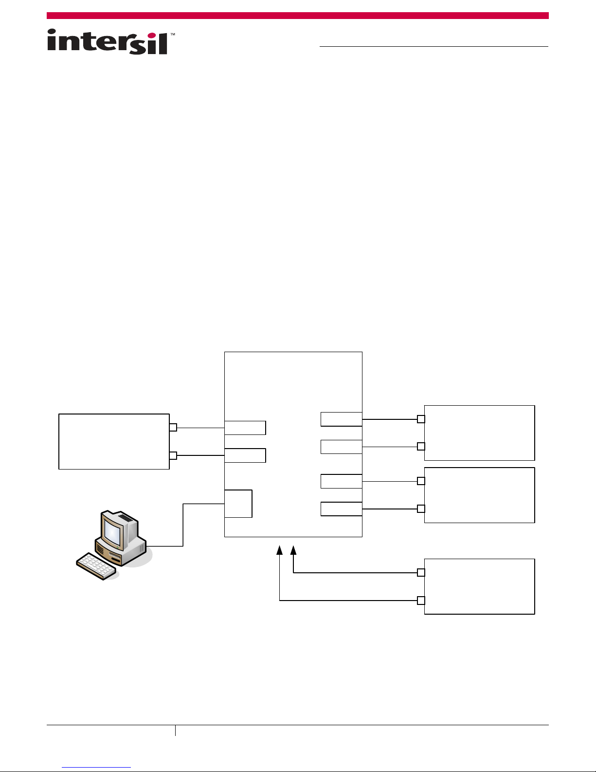
• One AC adaptor or one adjustable 25V/6A DC power supply
• Two adjustable electronic loads with constant current mode
and constant voltage mode
•One Volt Meter
• One 500MHz four-channel oscilloscope with voltage and
current probes
• A Personal Computer (PC) with ISL88731(C) control
software and drivers (all available on the self extracting
archive file ISL88731_v3.0_Installer.exe available for
download from www.Intersil.com)
Note: The National Instruments Runtime Engine must be
installed before connecting the evaluation board to your PC.
The Runtime Engine contains driver files required by the New
Hardware Wizard.
SYSTEM
SYSTEM
OUTPUT
OUTPUT
-
+
-
-
+
+
SYSTEM LOAD
SYSTEM LOAD
OR
OR
ELECTRONIC LOAD
ELECTRONIC LOAD
FIGURE 1. ISL88731(C)EVAL2Z HARDWARE CONNECTION DIAGRAM
June 27, 2011
AN1404.2
1
1-888-INTERSIL or 1-888-468-3774
-
-
USB
USB
TO VARIOUS
TO VARIOUS TEST POINTS
TEST POINTS
CAUTION: These devices are sensitive to electrostatic discharge; follow proper IC Handling Procedures.
| Intersil (and design) is a trademark owned by Intersil Corporation or one of its subsidiaries.
+
BATTERY
BATTERY
OUTPUT
OUTPUT
Copyright Intersil Americas Inc. 2010, 2011. All Rights Reserved.
All other trademarks mentioned are the property of their respective owners.
-
+
+
-
-
+
+
BATTERY PACK
BATTERY PACK
OR
OR
ELECTRONIC LOAD
ELECTRONIC LOAD
DC VOLTMETER
DC VOLTMETER
<10mV to >20v
Page 2
Application Note 1404
Download, Extract and Install the Software
Download the self extracting archive file
ISL88731_v3.0_Installer.exe. The URL for the file is:
http://www.intersil.com/data/ev/isl88731_control_v3_sw_in
staller.zip
It will create a folder (“ISL88731 Installer”) in the folder that
holds the self extracting file. A dialog box will give you the
opportunity to change the location of the extracted files.
Make a note of the location of the folder. You will need to direct
the New Hardware Wizard to this folder for the driver.
Software Installation
Both the ISL88731(C) control program and the National
Instruments run time engine are installed from the “ISL88731
Installer” folder. Navigate to the folder and double click the
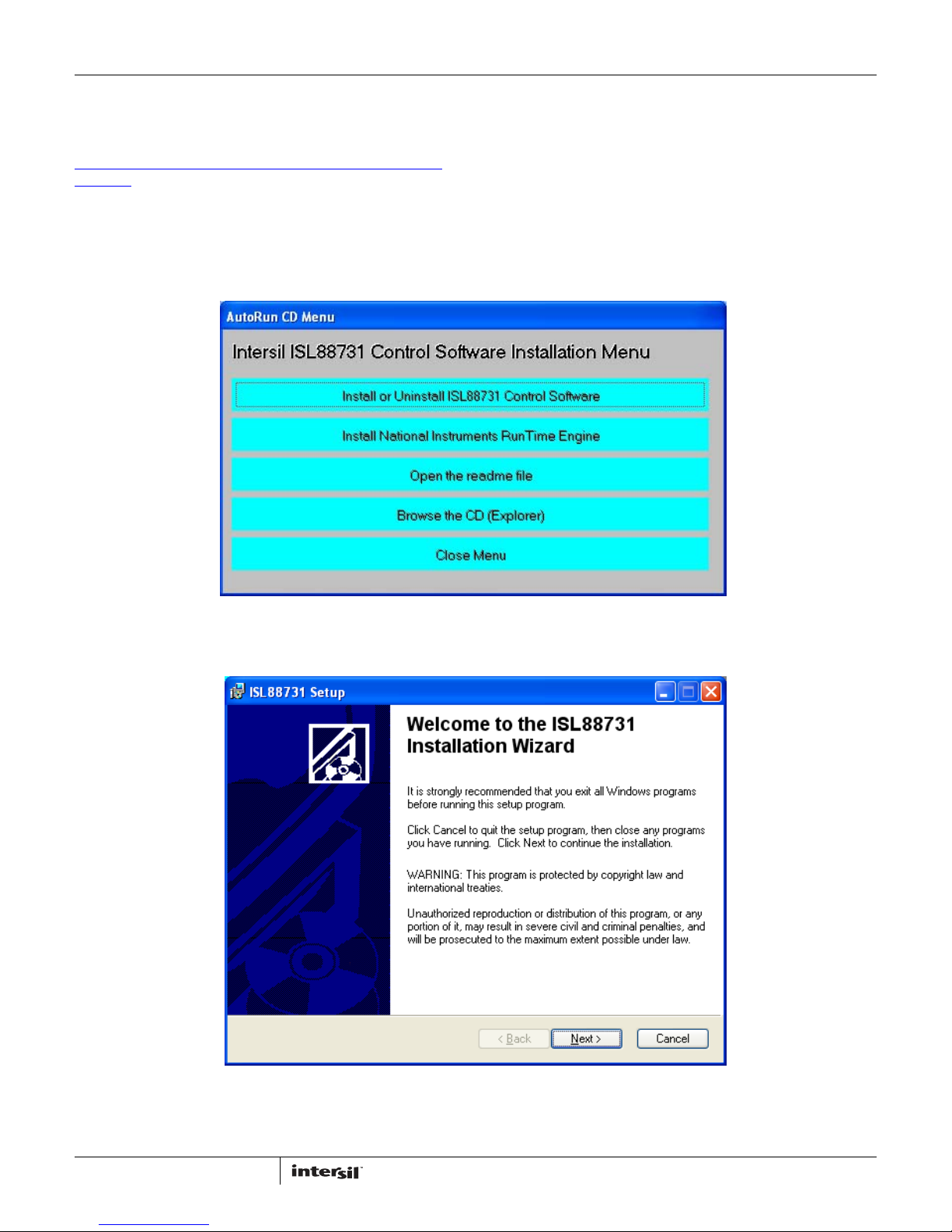
“AutoRun.exe” file. You should see the window as shown in
Figure 2.
Click on the “Install or Uninstall ISL88731 Control Software” to
run the Installation Wizard.
You should now see a window as shown in Figure 3.
FIGURE 2. ISL88731(C)EVAL2Z CONTROL SOFTWARE INSTALLATION MENU
FIGURE 3. ISL88731(C)EVAL2Z CONTROL SOFTWARE INSTALLATION WIZARD
2
AN1404.2
June 27, 2011
Page 3
Application Note 1404
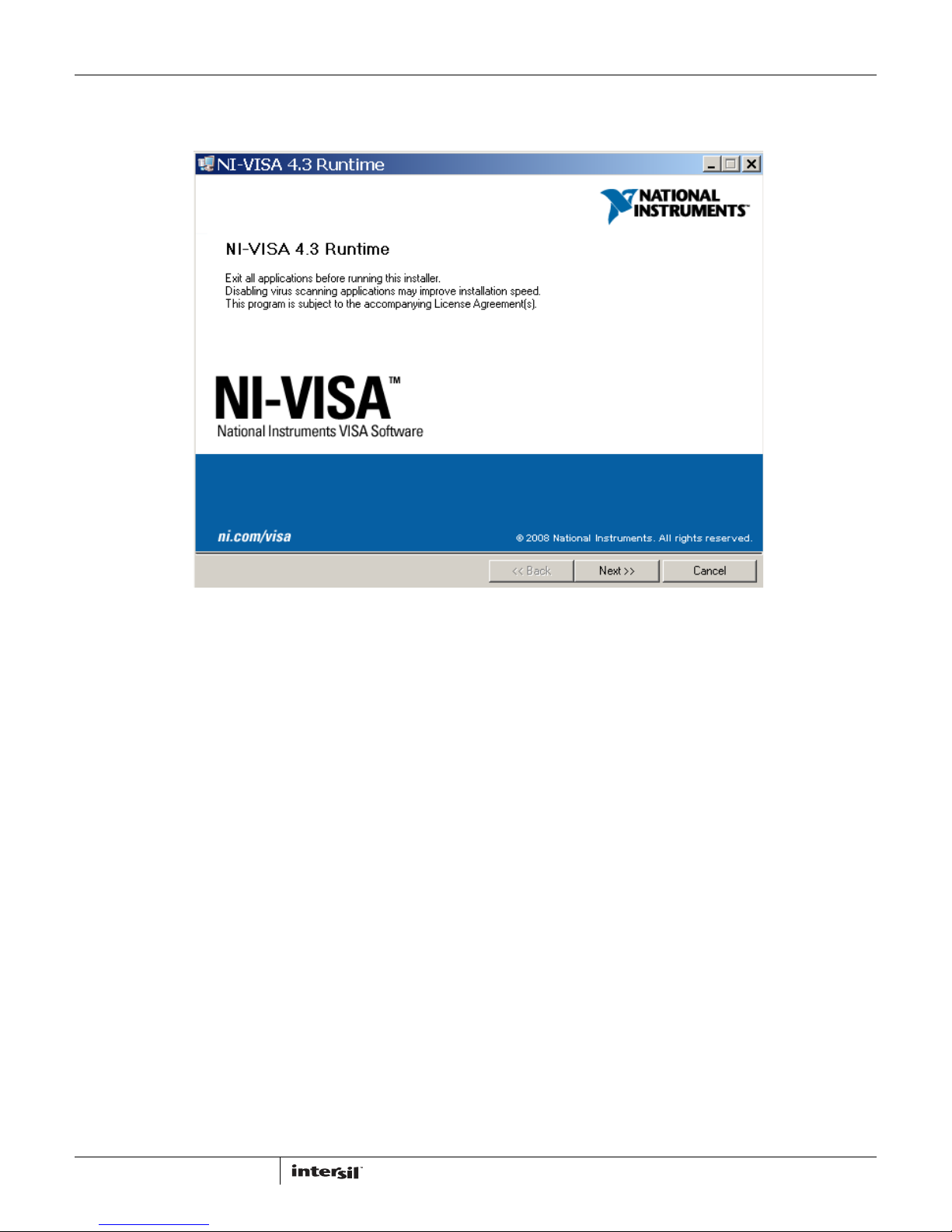
In most PCs the National Instruments Runtime Engine will be
installed automatically after the ISL88731(C) control software.
You should see the window as shown in Figure 4.
FIGURE 4. NATIONAL INSTRUMENTS RUNTIME ENGINE INSTALLATION WIZARD
Follow the instructions to install the Runtime Engine. If it does
not run automatically, click “Install National Instruments
Runtime Engine” on the ISL88731(C)EVAL2Z Control Software
Installation Menu (see Figure 2). After installation, click on the
Close Menu button.
Driver Installation
Connect the ISL88731(C)EVAL2Z to the USB port of your PC.
Note: The SMBus part of the ISL88731(C) and the USB-SMBus
interface are powered by the 5V from the USB port on the PC.
It is not necessary to have other power supplies connected to
the evaluation board to read or write to the ISL88731(C).
When WINDOWS detects new hardware, the new hardware
wizard should appear. Direct it to look for the driver
information file in the “ISL88731 Installer” folder (extracted
from the downloaded file). In some systems, it may be
necessary to specify the driver information file
(USB-I2C_WDM.inf).
Run the ISL88731 Application
ISL88731(C) control software should now appear in your
Start/All Programs list. Click on it to run the application.
3
AN1404.2
June 27, 2011
Page 4
Application Note 1404
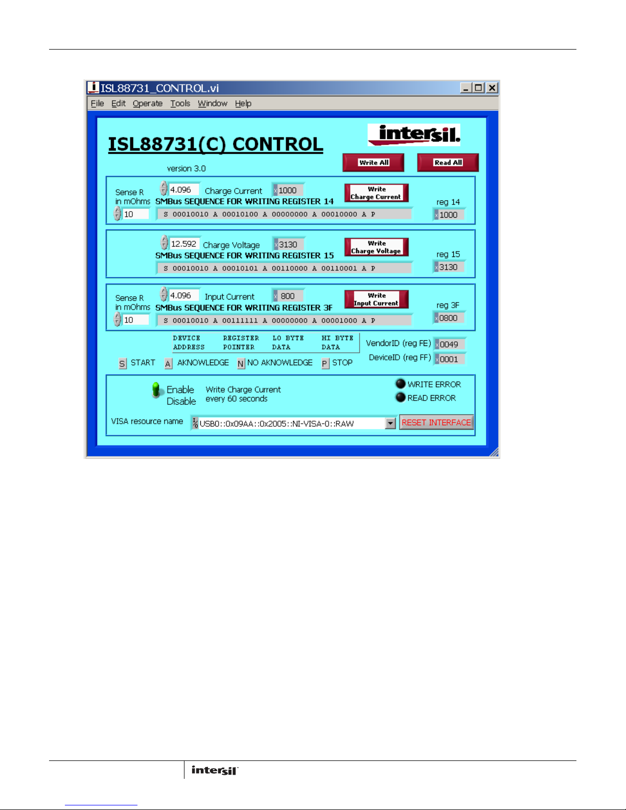
Figure 5 shows a screen shot of the ISL88731(C) control software user interface.
FIGURE 5. ISL88731(C)EVAL2Z CONTROL SOFTWARE SCREEN SHOT
4
AN1404.2
June 27, 2011
Page 5
Application Note 1404
Enable the Output
When power is applied to the ISL88731(C), the Charge Current
and Charge Voltage Registers are 0x0000 and the output is
disabled. The output is enabled by writing valid, non-zero
values to these 2 registers. See the ISL88731(C) datasheet for
valid values.
The ISL88731(C) is also disabled if the ACIN pin is below 3.2V.
An Input voltage >13.1V will pull ACIN above 3.2V. The
minimum input voltage can be adjusted on the evaluation
board by changing R
or R7 (see Figure 10).
6
Description of the User Interface Controls
and Display Information
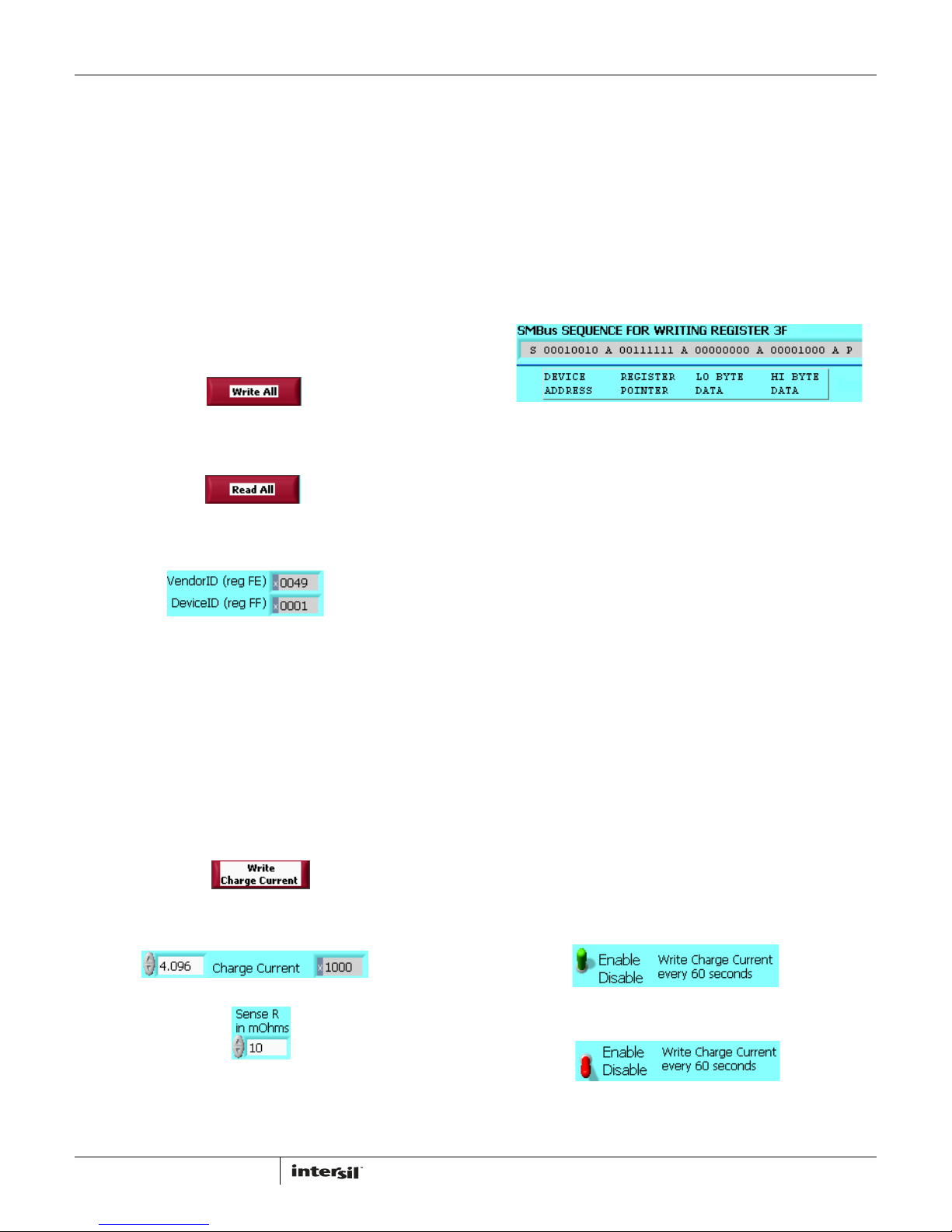
Clicking the “Write All” button will write the indicated SMBus
sequences to Registers 14, 15 and 3F in the ISL88731(C).
Clicking on the “Read All” button will read all 5 registers in the
ISL88731(C) and display the results in the grey indicators
below the “Read All” button.
If the device and the interface are operating normally, the
VendorID (reg FE) and the DeviceID (reg FF) will display as
follows:
If the VendorID (reg FE) and DeviceID (reg FF) remain 0000 it
indicates a communication problem.
If the Visa resource name is blank, it indicates a problem with
the USB communication.
Clicking on the “RESET INTERFACE” button may correct the
problem. If not, try closing the software, remove power and
USB connections from the evaluation board, then reconnect
and restart.
Note the register contents in the user interface are updated
ONLY when the “Read All” button is clicked.
The “Write Charge Current” button sends only the charge current
command to the ISL88731(C). Other registers are unchanged.
The small white window next to “Charge Current” accepts
inputs in Amps, and converts them the hexadecimal (hex)
value to be written to the ISL88731(C) in the grey window.
the enter key, the display will change to 4.096. The value can
be incremented and decremented with the up/down arrows at
the left of the window.
The Sense R inputs are used to calculate the hexadecimal
(hex) values and the SMBus sequences for the Charge Current
limit and Input Current limit entered in the white boxes. The
evaluation board is built with 10mΩ sense resistors. If you
change them to another value, enter the new value to get
correct calculations.
After entering a number in the white box, hitting the enter key
or clicking on another area will enter the value and the
resulting hex value and the SMBus sequence will be calculated
and displayed.
.
S = the Start condition, A = the Acknowledge, P = the Stop
condition.
Note: The LO byte is sent first. The HI byte is sent second.
When writing 0x41A0, 0xA0 is written first and 0x41 is sent
second.
Important Note: The SMBus commands are NOT sent until one
of the WRITE buttons is clicked (i.e. Write All or Write Charge
Current).
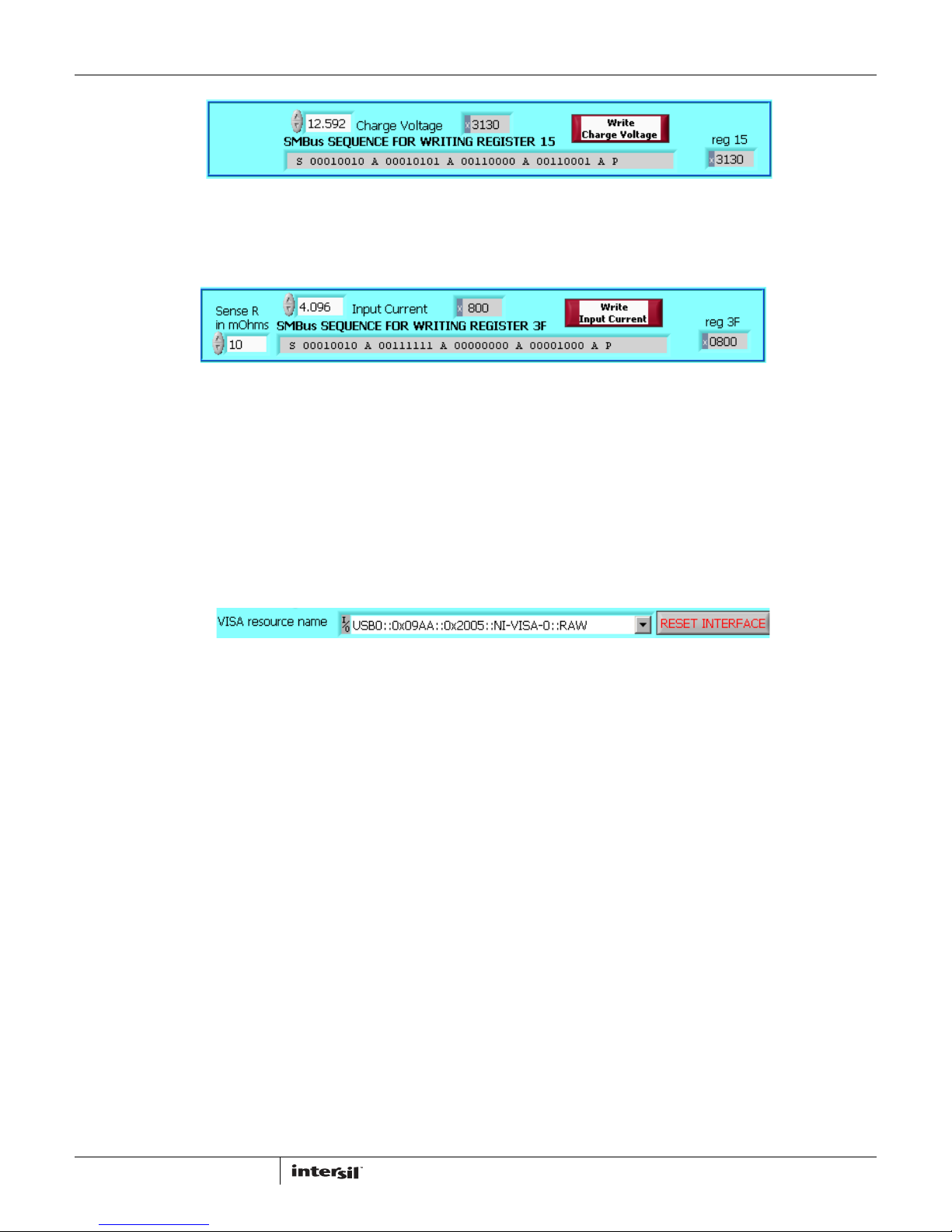
The “Write Charge Voltage” button writes only the Charge
Voltage register. Other registers are unchanged.
The small white window accepts Charge Voltage (in Volts) and
calculates the hexadecimal value and the SMBus sequence to
write to the ISL88731(C). The SMBus command is sent when
the “Write Charge Voltage” or “Write All” button is clicked. See
Figure 8.
The “Write Input Current” button writes only the Input Current
register. Other registers are unchanged. The small white
window accepts Input Current Limit in Amps and calculates
the hex value and the SMBus sequence to be written to the
ISL88731(C). The Sense R input Is used to calculate the hex
value and the SMBus sequence. The SMBus command is sent
when the “Write Input Current” or “Write All” button is clicked.
See Figure 9.
The ISL88731(C) will shut down unless it receives Charge Voltage
or Charge Current commands every 175s. This is a safety feature
that prevents overcharging batteries if bus master has stopped
functioning. The control software includes the function to write
the Charge Current register every 60 seconds, which can be
enabled or disabled as shown in Figure 6 and Figure 7.
The hex value depends on the value entered in Sense R.
The value in the white window will be forced to the nearest
valid number that can be produced by the DAC in the
ISL88731(C). That is, after entering 4 and hitting the enter key,
the display will change to 3.968. After entering 4.1 and hitting
5
FIGURE 6. ENABLE WRITING CHARGE CURRENT REGISTER EVERY
60 SECONDS
FIGURE 7. DISABLE WRITING CHARGE CURRENT
REGISTER EVERY 60 SECONDS
AN1404.2
June 27, 2011
Page 6
Application Note 1404
FIGURE 8. WRITE CHARGE VOLTAGE BLOCK
FIGURE 9. WRITE INPUT CURRENT BLOCK
Interface Troubleshooting
When the evaluation board is connected to the PC by a USB
cable and the software is running, the software assigns a VISA
resource name.
If this window is blank, it indicates a problem with
communication between the PC and the micro controller on
the evaluation board. Check and correct the connection of the
USB cable to your PC and the evaluation board. Click on the
“RESET INTERFACE” button.
.
If you still get no VISA resource name, Close and restart the
ISL88731(C) control software.
If you still get no VISA resource name, Open the Device
Manager (Control Panel/System/Device Manager) with the
ISL88731(C)EVAL2Z evaluation board connected to your USB
port. You should see a device named “NI-VISA USB Device”. If it
is not in the list of devices, the driver may not be correctly
installed. Run the New Hardware wizard.
If you still get no VISA resource name, contact your Intersil
Field Application Engineer for assistance.
6
AN1404.2
June 27, 2011
Page 7
Application Note 1404
7
AN1404.2
June 27, 2011
ISL88731(C)EVAL2Z Schematics
SEE PAGE 2
LGATE-PGDN
PHASE-PGND
UGATE-PGND
CSON
R20
100
TP27TP26
CSOP
R17
4.7
C11
1UF
LGATE
C10
1UF
BOOT
CSSN
R13
3
1
D2
L1
22
R23
0.1UF
C24
0.01
R19
TP19 TP20
TP25
0.01
R24
SCL
TP10
4
3
10UF
C14
PHASE
C17
10UF
VREF
VCC
ACIN
VBAT
CSSP
0.01UF
C7
TP7
TP6
TP9
TP8
TP5
TP4
TP12
33K
R7
0.01UF
C2
1K
R30
100K
R11
R6
J1
TP1
1
J2
TP2
SI4835BDY
Q1
5
7
8
4
1
2
3
BSS138
Q2
3
1
2
0.1UF
C6
100K
R4 R2
10
R1
3
1
D1
0.1UF
0.047UF
C9
10
R3
0.01
R5
TP11
0.01UF
C3
10K
R10
Q8
2
2
1
TP31
2
1
TP30
C1
3
214
876
5
Q11
C5
TP17
TP16
TP15
TP14
3
15
11
21
6
26
24
9
10
23
19
7
5
16
14
1
20
4
8
12
29
22
28
27
18
17
25
13
2
U1
TP13
314
876
5
C8
R18
2
1
876
5
Q9
IRF7821
IRF7821
IRF7821
0
1UF
VDDSMB
0.22UF
0
1UF
ISL88731
SDA
UGATE
0.01UF
C4
100K
C16
VCOMP
ICOMP
TP18
VDDP
8.2UH
100K
6
OPEN
R22C23
OPEN
J6
J5
TP21
1
TP22
J9
J7
TP23
J8
TP24
C12
0.1UF
C13
10UF
10UF
C15
1
2
1
2
EP
VREF
NC
ICM
ACOK
NC
CSON
DCIN
PHASE
UGATE
BOOT
VCC
CSSN
CSSP
LGATE
PGND
CSOP
VDDSMB
ICOMP
NC
VCOMP
SDA
SCL
VFB
NC
VDDP
GND
ACIN
NC
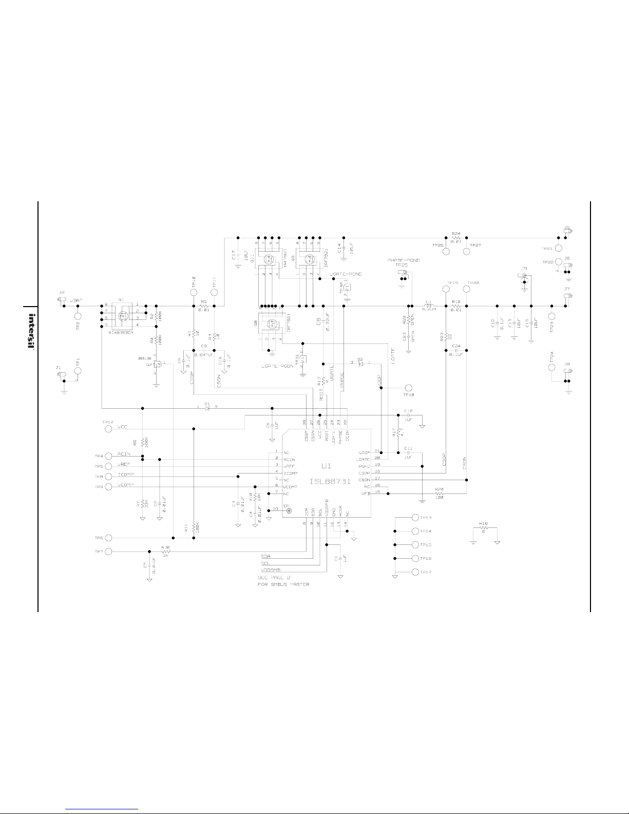
FIGURE 10. ISL88731(C)EVAL2Z SCHEMATIC
(C)
Page 8
Application Note 1404
8
AN1404.2
June 27, 2011
ISL88731(C)EVAL2Z Schematics (Continued)
SDA
GND
SCL
DEBUG
R311
R310
2
1
F325
6
5
43
2
1
U303
C304
C307
R304
C305
R303
65
4
32
1
J301
R302
C308
C309
1
TP3041TP305
R305
6
8
9
7
10111213141516
17
18
19
20
21
22
23
24
25
26
27
28
29
30
31
32
1
2
3
4
5
U301
1
TP306
1
TP303
R307
R309
R399
1
TP300
1
TP3011TP302
1.8K
1.8K
0
VDDSMB
SCL
SDA
SN65220DBV
1UF
0.1UF
1K
0.1UF
0
897-30-004-90-000
0
1UF
0.1UF
1K
C8051F320
0
0
D
D
S
D
NC
NC
GND
B
GND
A
D
DD
D
USB
1
MOUNT
2
3
4
MOUNT
DD
D
P0.1
GND
D+
D-
VDD
P3.0/C2D
P2.7
P2.6
P2.5
P2.4
P2.3
P2.2
P1.2
P1.3
P1.4
P1.5
P1.6
P1.7
P2.0
P2.1
P0.6
P1.1
P0.3
P0.4
P0.5
P0.7
P0.2
P1.0
P0.0
REGIN
VBUS
RST/C2CK
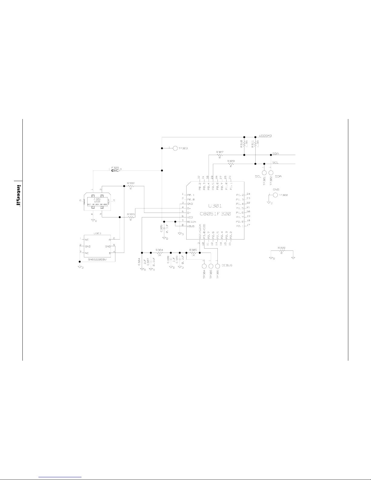
FIGURE 11. ISL88731(C)EVAL2Z SCHEMATIC (USB - SMBUS INTERFACE)
Page 9
Application Note 1404
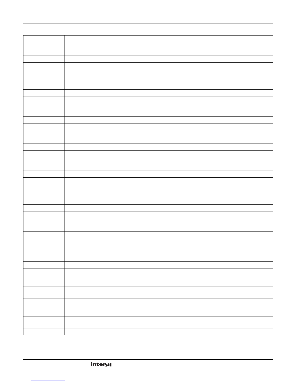
TABLE 1. ISL88731(C)EVAL2Z BILL OF MATERIALS
REF DES PART NUMBER VALUE MANUFACTURER DESCRIPTION
C1, C10, C11 H1045-00105-6R3V10 1µF GENERIC Multilayer Capacitor
C24 H1044-00104-16V10 0.1µF GENERIC Multilayer Capacitor
C2-C4, C7 H1045-00103-25V10 0.01µF GENERIC Multilayer Capacitor
C304, C308 H1045-00105-6R3V10 1µF GENERIC Multilayer Capacitor
C5 H1046-00105-25V10 1µF GENERIC Multilayer Capacitor
C6, C16 H1045-00104-25V10 0.1µF GENERIC Multilayer Capacitor
C8 H1045-00224-25V20 0.22µF GENERIC Multilayer Capacitor
C9 H1045-00473-25V10 0.047µF GENERIC Multilayer Capacitor
D1, D2 BAT54 DIODES 30V Schottky Diode
J1, J6, J8 164-6218 MOUSER Single Point RA PCB Mount (Black)
J2, J5, J7 164-6219 MOUSER Single Point RA PCB Mount (Red)
J9, TP25 131-4353-00 TEKTRONIX Scope Probe Test Point PCB Mount
L1 HM65-8R2 8.2µH BI-Tech Shielded SMD Inductor
Q1 SI4835BDY VISHAY 30V, -7.4A P-Channel MOSFET
Q2 BSS138LT1 ON-SEMI 200mA 50V N-Channel Power MOSFET
R1, R3 H2511-00100-1/16W5 10 GENERIC Thick Film Chip Resistor
R10 H2511-01002-1/10W5 10k GENERIC Thick Film Chip Resistor
R13 H2511-00R00-1/16W1 0 GENERIC Thick Film Chip Resistor
R17 H2511-004R7-1/16W5 4.7 GENERIC Thick Film Chip Resistor
R18 H2511-00R00-1/16W 0 GENERIC Thick Film Chip Resistor
R2, R4 H2511-01003-1/16W1 100k GENERIC Thick Film Chip Resistor
R20 H2511-01000-1/16W5 100 GENERIC Thick Film Chip Resistor
R23 H2511-00220-1/16W5 22 GENERIC Thick Film Chip Resistor
R30 H2511-01001-1/16W5 1k GENERIC Thick Film Chip Resistor
R310, R311 H2511-01801-1/16W5 1.8k GENERIC Thick Film Chip Resistor
R5, R19, R24 WSL2512R0100FEA 0.01 VISHAY Power Metal Strip Resistor
R6, R11 H2511-01003-1/10W5 100k GENERIC Thick Film Chip Resistor
R7 H2511-03302-1/16W5 33k GENERIC Thick Film Chip Resistor
U1 ISL88731HRTZ
or
ISL88731CHRTZ
C12 C1608X7R1H104M 0.1µF TDK Multilayer Capacitor
C13-C15, C17 H1065-00106-25V20 10µF GENERIC Multilayer Capacitor
C305, C307, C309 H1045-00104-16V10 0.1µF GENERIC Multilayer Capacitor
F325 MICROSMD050F RAYCHEM-TYCO PolySwitch SM Resetable Fuse
INTERSIL SMBus Level 2 Battery Charger
J301 897-30-004-90-000 MIL-MAX Type B Receptacle USB Connector
Q8, Q9, Q11 IRF7821PBF IR 30V, +13.6A N-Channel HEXFET Power MOSFET
R302, R303, R307,
R309, R399
R304, R305 H2511-01001-1/16W1 1k GENERIC Thick Film Chip Resistor
U301 C8051F320 SILICON
U303 SN65220DBV TI SINGLE USB Port Transient Suppressors
H2511-00R00-1/16W1 GENERIC Thick Film Chip Resistor
9
LABRATORIES
General Purpose MicroControllers
AN1404.2
June 27, 2011
Page 10
Application Note 1404
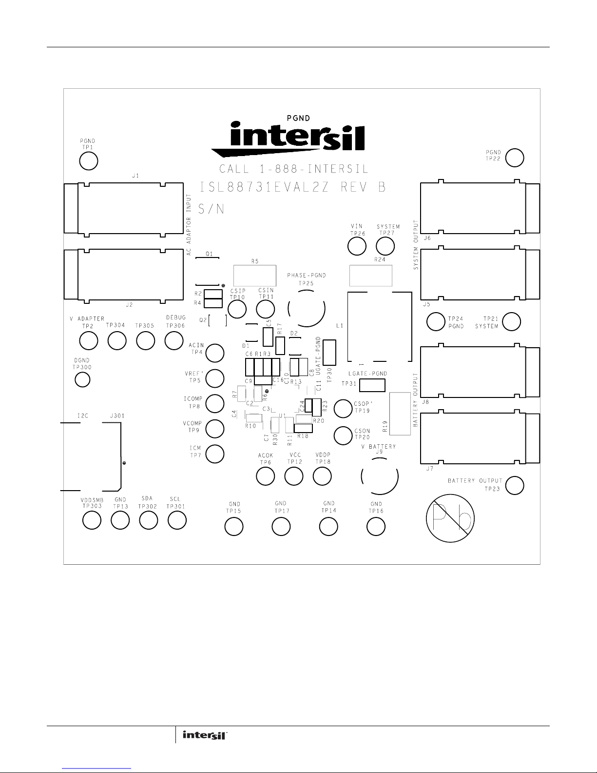
ISL88731(C)EVAL2Z Evaluation Board Layout
10
FIGURE 12. TOP SILK SCREEN
AN1404.2
June 27, 2011
Page 11
Application Note 1404
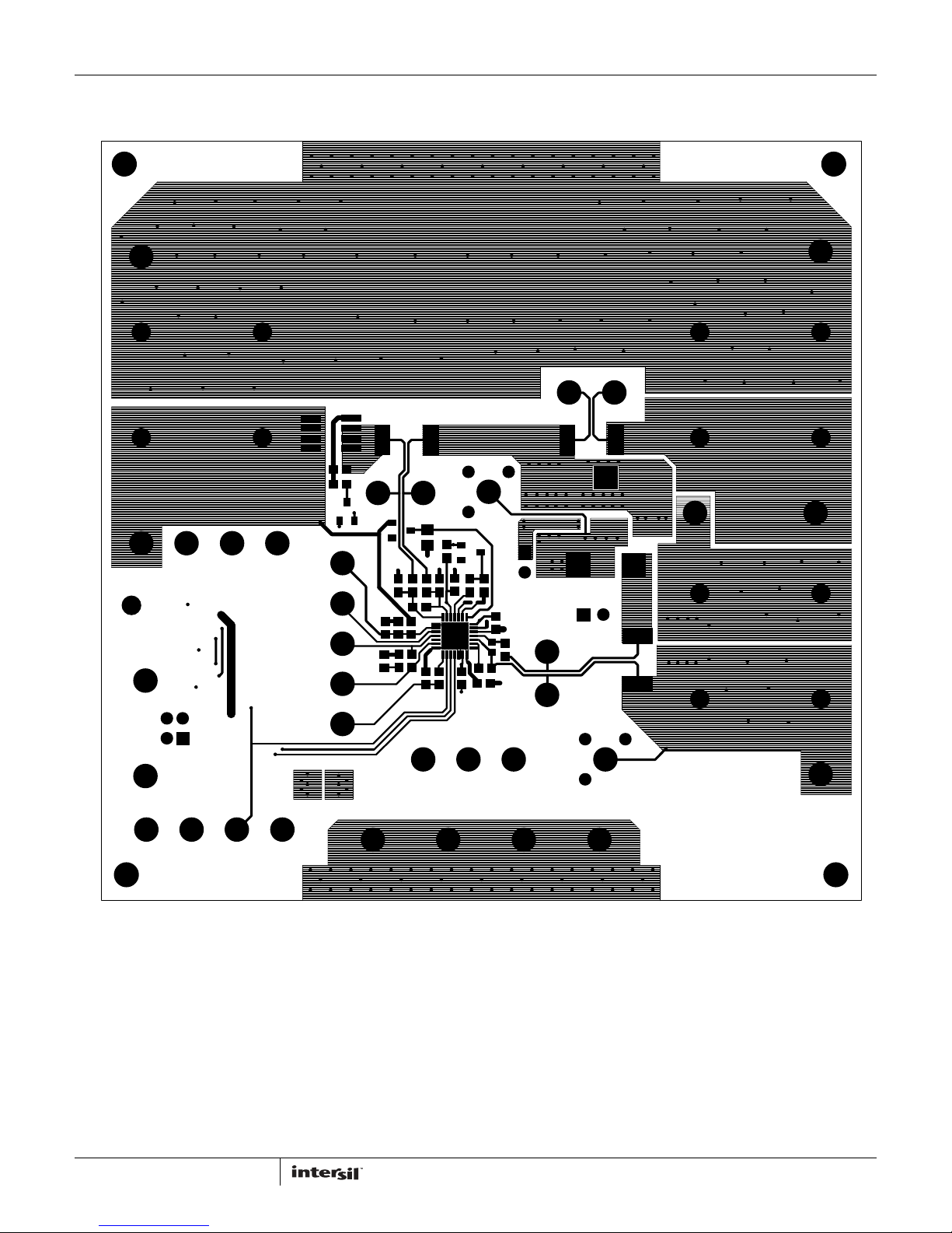
ISL88731(C)EVAL2Z Evaluation Board Layout (Continued)
11
FIGURE 13. TOP COPPER
AN1404.2
June 27, 2011
Page 12
Application Note 1404
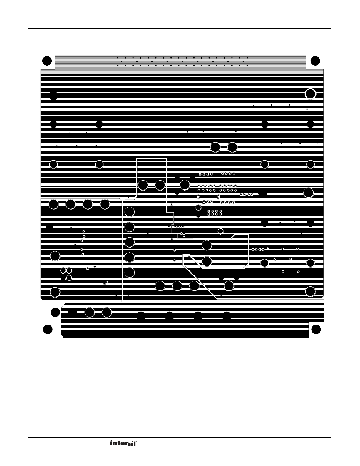
ISL88731(C)EVAL2Z Evaluation Board Layout (Continued)
12
FIGURE 14. LAYER 2 (GROUNDS) (TOP VIEW)
AN1404.2
June 27, 2011
Page 13
Application Note 1404
ISL88731(C)EVAL2Z Evaluation Board Layout (Continued)
13
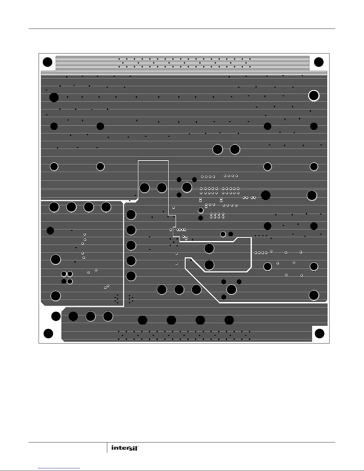
FIGURE 15. LAYER 3 (GROUNDS) (TOP VIEW)
AN1404.2
June 27, 2011
Page 14
Application Note 1404
ISL88731(C)EVAL2Z Evaluation Board Layout (Continued)
14
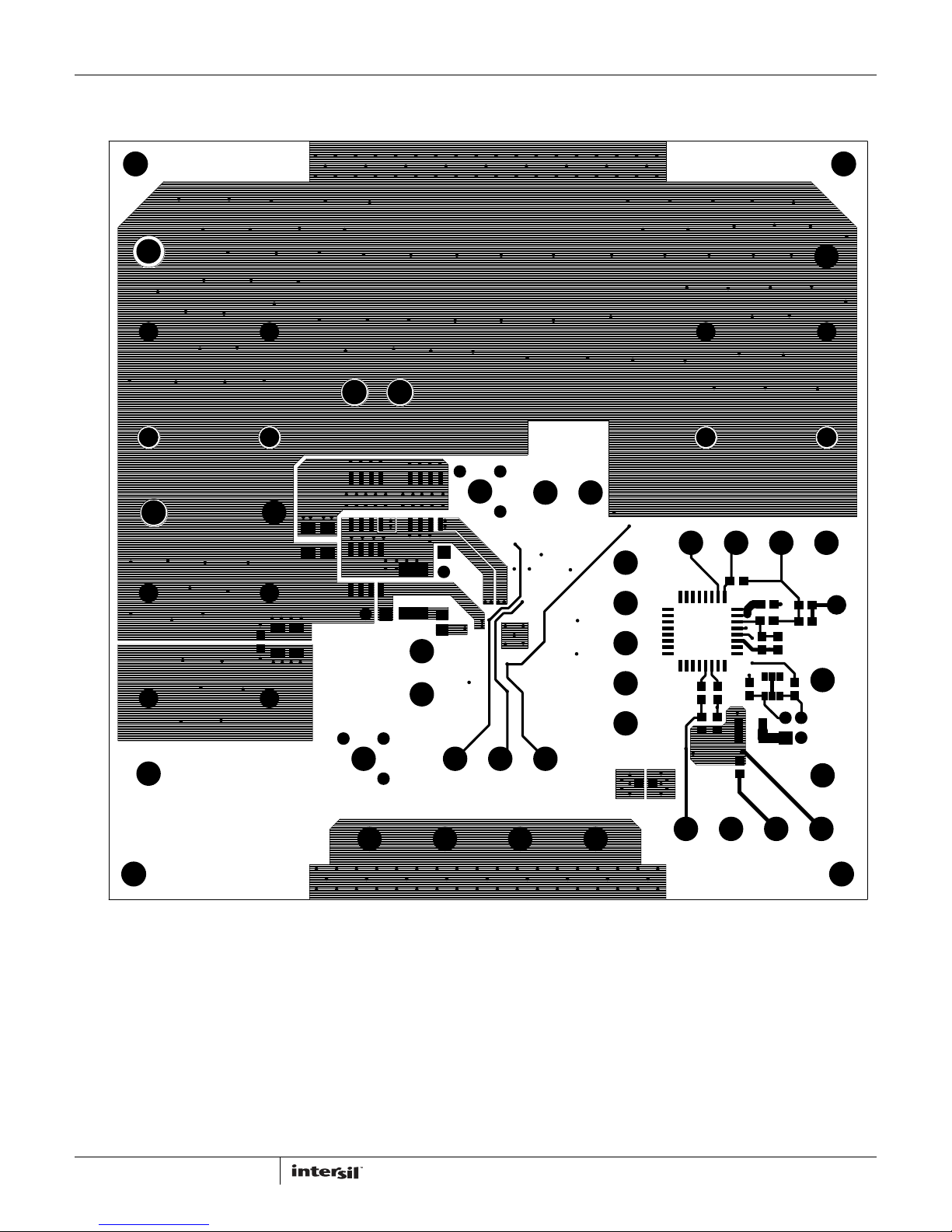
FIGURE 16. BOTTOM COPPER (BOTTOM VIEW)
AN1404.2
June 27, 2011
Page 15
Application Note 1404
ISL88731(C)EVAL2Z Evaluation Board Layout (Continued)
Intersil Corporation reserves the right to make changes in circuit design, software and/or specifications at any time without notice. Accordingly, the reader is
cautioned to verify that the Application Note or Technical Brief is current before proceeding.
For information regarding Intersil Corporation and its products, see www.intersil.com
15
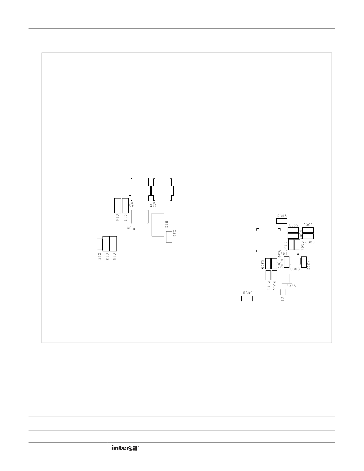
FIGURE 17. BOTTOM SILK SCREEN (BOTTOM VIEW)
AN1404.2
June 27, 2011
Page 16

Mouser Electronics
Authorized Distributor
Click to View Pricing, Inventory, Delivery & Lifecycle Information:
Intersil:
ISL88731CEVAL2Z
 Loading...