

Page 1
USER’S MANUAL
R
2
R10.8V
V
OUT
0.8V–
-------------------------------
=
(EQ. 1)
ISL85003EVAL2Z, ISL85003AEVAL2Z
Evaluation Board User Guide
Description
The ISL85003 and ISL85003A kits are intended for use for
point-of-load applications sourcing from 4.5V to 18V. The kits
are used to demonstrate the performance of the ISL85003
and ISL85003A, low quiescent current high efficiency
synchronous buck regulators.
The ISL85003 and ISL85003A are offered in a 4x3mm dual flat
no lead (DFN) package.
Specifications
The boards are designed to operate at the following operating
conditions:
• Input voltage range from 4.5V to 18V
• Resistor programmable output voltage from 0.8V,
• Up to 3A output current
• Current mode control
- DCM/CCM
- Internal or external compensation options
- 500kHz switching frequency option
- External synchronization up to 2MHz on ISL85003
• Adjustable soft-start time on the ISL85003A
• Operating junction temperature range: -40°C to +125°C
±1%
Quick Setup Guide
1. Ensure that the circuit is correctly connected to the supply
and loads prior to applying any power.
2. Connect the bias supply to VIN, the plus terminal to VIN (P4)
and the negative return to PGND (P5).
3. Connect the output load to V0, the plus terminal to V0 (P8)
and the negative return to PGND (P9).
4. Verify that the position is PWM or PFM for SW2.
5. Verify that the position is ON for SW1.
6. Turn on the power supply.
7. Verify the output voltage is 5V for VO.
Recommended Equipment
The following materials are recommended to perform testing:
• 0V to 25V power supply with at least 10A source current
capability
• Electronic loads capable of sinking current up to 7A
• Digital multimeters (DMMs)
• 100MHz quad-trace oscilloscope
• Signal generator
AN1930
Rev.1.00
Aug 28, 2014
Key Board Features
•Small, compact design
• Switch selectable EN (enabled/disabled)
• Switch selectable MODE (auto-DCM/forced-PWM)
• Connectors and test points for easy probing
References
• ISL85003, ISL85003A datasheet
Ordering Information
PART NUMBER DESCRIPTION
ISL85003EVAL2Z Evaluation Board for ISL85003FRZ and
ISL85003AFRZ
Evaluating the Other Output
Voltage
The ISL85003 and ISL85003A kit outputs are preset to 5V for
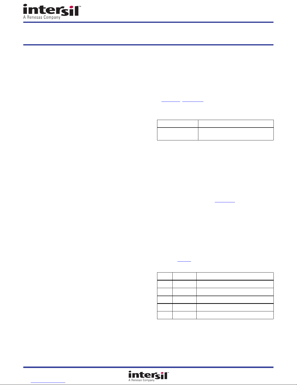
V
; however, the output voltages are programmed using an
OUT
external resistor divider that scales the feedback relative to the
internal reference voltage. The output voltage programming
resistor, R
resistor, R1, and the desired regulator output voltage, V
The value for the feedback resistor R1 is typically between
10kΩ and 400kΩ as shown in Equation 1
If the output voltage desired is 0.8V, then R2 is left
unpopulated. R1 is still required to set the low frequency pole
of the modulator compensation.
Switch Control
The ISL85003 and ISL85003A evaluation boards contain SW1
and SW2 for various controls of the ISL85003 and ISL85003A
circuitries. Table 1 details this function.
SW1 ENABLE FUNCTION
SW2 MODE FUNCTION
, will depend on the value chosen for the feedback
2
.
TABLE 1. SWI TCH SE TT INGS
1OFFDisable V0
3ONEnable V0
1DCMForce DCM
3 PWM Fixed PWM frequency at light load
OUT
.
Aug 28, 2014
AN1930 Rev.1.00 Page 1 of 5
Page 2
ISL85003EVAL2Z, ISL85003AEVAL2Z
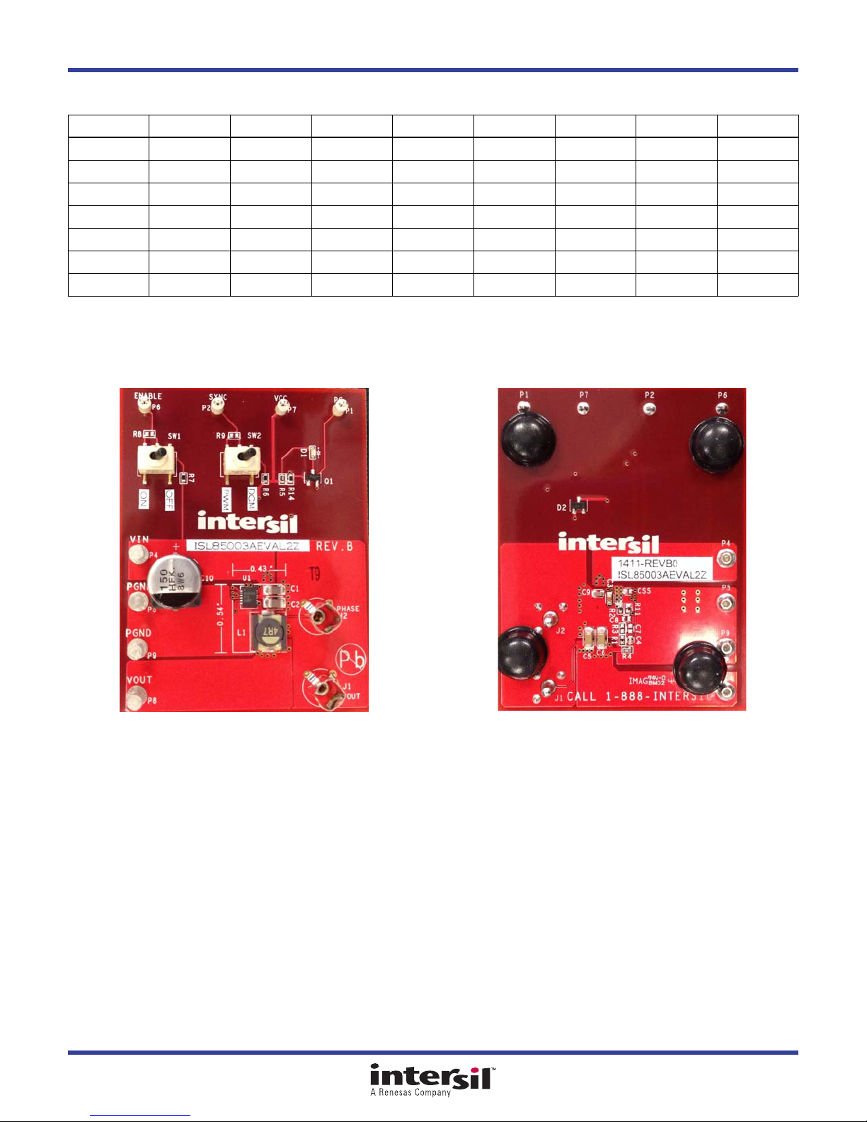
Components Selection
V
OUT
C
, C
1
2
C
5
C
6
C
4
L
1
R
1
R
2
NOTE: VIN = 12V, I
that require high output capacitance greater than 200µF, R
0.8V 1V 1.2V 1.5V 1.8V 2.5V 3.3V 5V
10µF 10µF 10µF 10µF 10µF 10µF 10µF 10µF
22µF 22µF 22µF 47µF 47µF 47µF 47µF 47µF
22µF 22µF 22µF 22µF 22µF 22µF 22µF 22µF
Open Open Open 4.7pF 4.7pF 4.7pF 4.7pF 4.7pF
1.8µH 2.2µH 2.2µH 3.3µH 3.3µH 3.3µH 4.7µH 4.7µH
301kΩ 301kΩ 301kΩ 301kΩ 301kΩ 301kΩ 301kΩ 301kΩ
Open 1.2MΩ 604kΩ 344kΩ 241kΩ 142kΩ 96.3kΩ 57.6kΩ
= 3A; The components selection table is a suggestion for typical application using internal compensation mode. For applications
OUT
should be adjusted to maintain a loop response bandwidth about 40kHz.
1
ISL85003EVAL2Z Evaluation Board
FIGURE 1. TOP VIEW FIGURE 2. BOTTOM VIEW
AN1930 Rev.1.00 Page 2 of 5
Aug 28, 2014
Page 3
AN1930 Rev.1.00 Page 3 of 5
Aug 28, 2014
ISL85003EVAL2Z, ISL85003AEVAL2Z
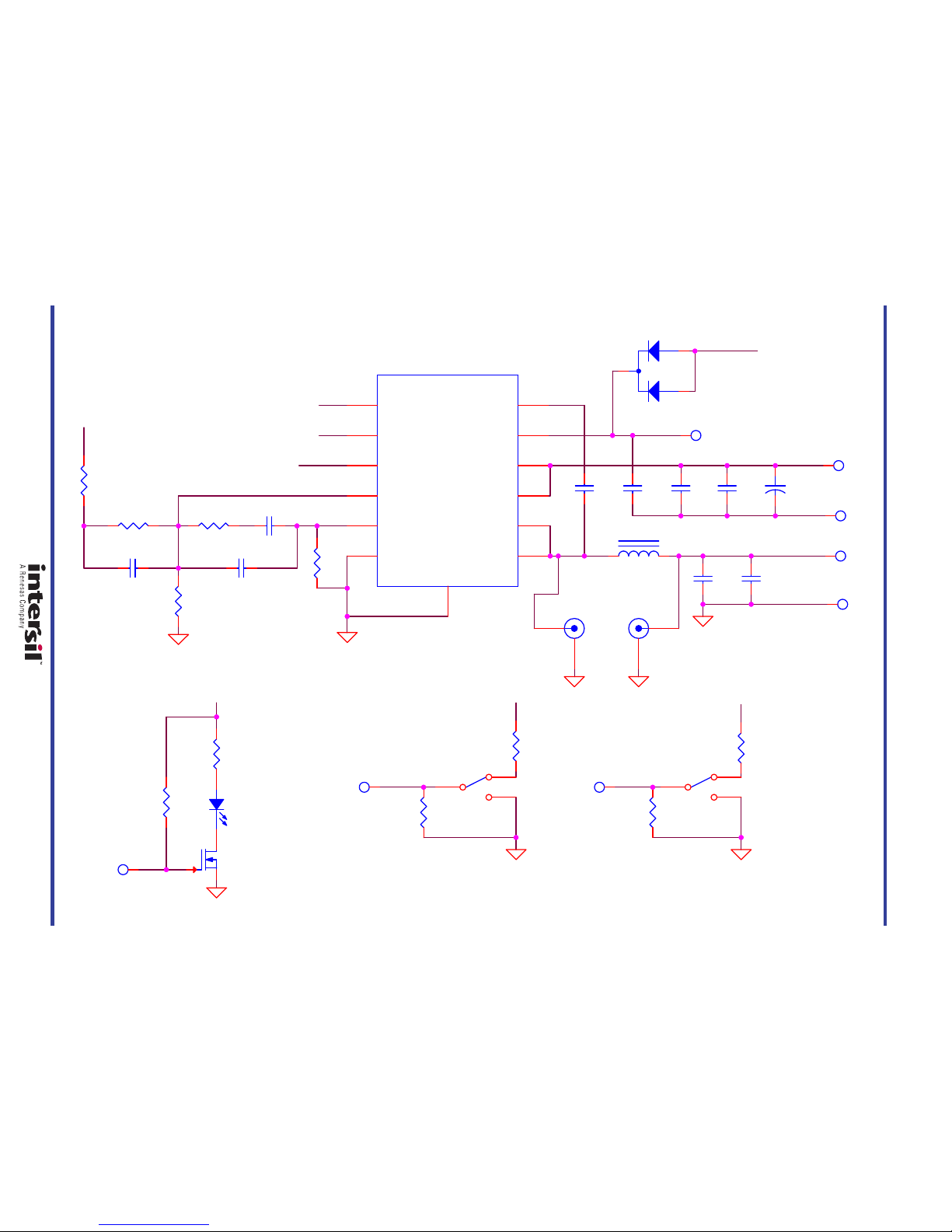
ISL85003EVAL2Z Rev B Schematic
VCC
EN
VOUT
SYNC
PG
OFF
EN
VIN
SYNC
DCM
PWM ON
VCCVCC
VOUT
D2
DNP
C1
10uF
R5
2k
C3
0.1uF
SW2
C4
4.7p
SW1
R9
DNP
P6
ENABLE
C5
47uF
+
C10
150uF
P1
PG
Q1
2N7002
R6
200k
R2
57.1k
C8
DNP
P7
VCC
C6
22uF
P2
SYNC
C2
10uF
R11
0
R3
DNP
R7
200k
C7
DNP
P8
VOUT
L1
4.7uH
D1
LTST-C190KGKT
P4
VIN
R14
200k
R1
301k
C9
1uF
P9
GND
R8
DNP
U1
ISL85003
PG
2
EN
3
FB
4
COMP
5
AGND
6
PHASE
7
PHASE
8
VIN
9
VIN
10
VDD
11
BOOT
12
EPAD
13
SYNC
1
R4
20
J2
PHASE
1
2
P5
GND
J1
VOUT
1
2
Page 4
ISL85003EVAL2Z, ISL85003AEVAL2Z
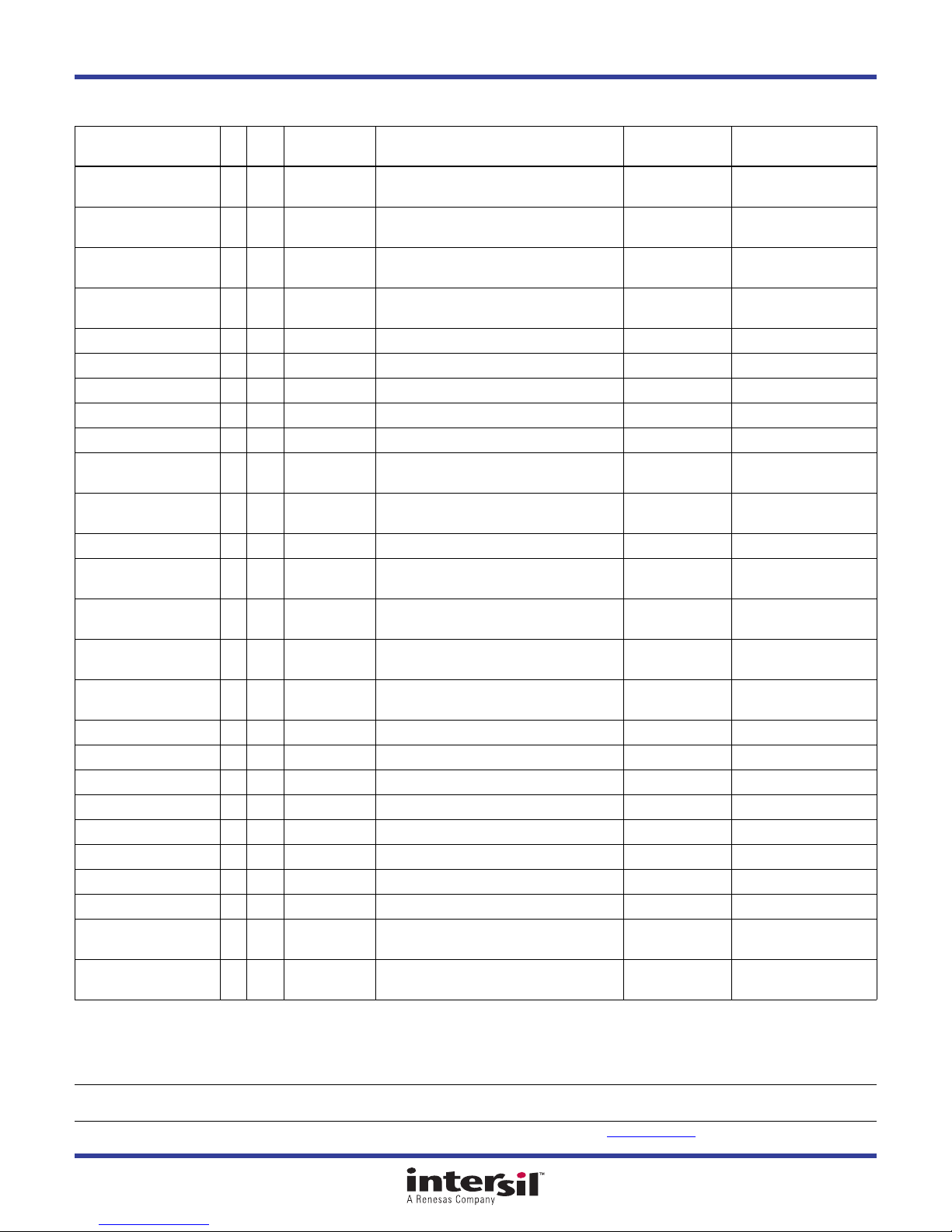
Bill of Materials
REFERENCE
PART NUMBER QTY UNITS
ISL85003FRZ 1 ea U1 IC-3A BUCK REGULATOR, 12P, DFN, 4X3,
ISL85003AFRZ 1 ea U1 IC-3A BUCK REGULATOR PWM, 12P, DFN, 4X3,
EEE-FK1H151P-T 1 ea C10 CAP, SMD, 10.3mm, 150µF, 50V, 20%, ROHS,
H1044-004R7-50VR25-T 1 ea C4 CAP, SMD, 0402, 4.7pF, 50V, 0.25pF, NPO,
H1044-DNP 0 ea C7, C8, CSS CAP, SMD, 0402, DNP-PLACE HOLDER, ROHS
H1045-00104-50V10-T 1 ea C3 CAP, SMD, 0603, 0.1µF, 50V, 10%, X7R, ROHS AVX 06035C104KAT2A
H1045-00105-16V10-T 1 ea C9 CAP, SMD, 0603, 1µF, 16V, 10%, X5R, ROHS MURATA GRM188R61C105KA12D
H1065-00106-25V10-T 2 ea C1, C2 CAP, SMD, 1206, 10µF, 25V, 10%, X7R, ROHS VENKEL C1206X7R250-106KNE
H1065-00226-25V10-T 2 ea C5, C6 CAP, SMD, 1206, 22µF, 25V, 10%, X5R, ROHS MURATA GRM31CR61E226KE15L
RLF7030T-4R7M3R4 1 ea L1 COIL-PWR INDUCTOR, SMD, 7.3X6.8mm,
131-4353-00 2 ea J1, J2 CONN-SCOPE PROBE TEST PT, COMPACT, PCB
1514-2 4 ea P4, P5, P8, P9 CONN-TURRET, TERMINAL POST, TH, ROHS KEYSTONE 1514-2
5002 4 ea P1, P2, P6, P7 CONN-MINI TEST POINT, VERTICAL, WHITE,
BAT54C-T 1 ea D2 DIODE-RECTIFIER, SMD, SOT23, 3P, 30V,
LTST-C190KGKT-T 1 ea D1 LED, SMD, 0603, GREEN CLEAR, 2V, 20mA,
2N7002LT1G-T 1 ea Q1 TRANSISTOR-MOS, N-CHANNEL, SMD, SOT23,
H2510-00R00-1/16W-T 1 ea R11 RES, SMD, 0402, 0Ω, 1/16W, 5%, TF, ROHS VENKEL CR0402-16W-00T
H2510-03013-1/16W1-T 1 ea R1 RES, SMD, 0402, 301k, 1/16W, 1%, TF, ROHS YAGEO RC0402FR-07301KL
H2510-05762-1/16W1-T 1 ea R2 RES, SMD, 0402, 57.6k, 1/16W, 1%, TF, ROHS PANASONIC ERJ-2RKF5762X
H2510-DNP 0 ea R3 RES, SMD, 0402, DNP, DNP, DNP, TF, ROHS
H2511-00200-1/10W1-T 1 ea R4 RES, SMD, 0603, 20Ω, 1/10W, 1%, TF, ROHS PANASONIC ERJ-3EKF20R0V
H2511-02001-1/10W1-T 1 ea R5 RES, SMD, 0603, 2k, 1/10W, 1%, TF, ROHS KOA RK73H1JTTD2001F
H2511-02003-1/10W1-T 3 ea R6, R7, R14 RES, SMD, 0603, 200k, 1/10W, 1%, TF, ROHS VENKEL CR0603-10W-2003FT
H2511-DNP 0 ea R8, R9 RES, SMD, 0603, DNP-PLACE HOLDER, ROHS
GT11MSCBE-T 2 ea SW1, SW2 SWITCH-TOGGLE, SMD, 6PIN, SPDT, 2POS, ON-
SJ-5003-BLACK 4 ea Bottom four
DESIGNATOR DESCRIPTION MFR MFR PART #
INTERSIL ISL85003FRZ
ROHS
INTERSIL ISL85003AFRZ
PANASONIC EEE-FK1H151P
MURATA GRM36COG4R7C050AQ
TDK RLF7030T-4R7M3R4
TEKTRONIX 131-4353-00
KEYSTONE 5002
FAIRCHILD BAT54C
LITEON/VISHAY LTST-C190KGKT
ON
SEMICONDUCTOR
ITT INDUSTRIES/
C&K DIVISION
3M SJ-5003SPBL
2N7002LT1G
GT11MSCBE
corners
ROHS
ALUM.ELEC.
ROHS
4.7µH, 20%, 3.5A, ROHS
MNT, ROHS
ROHS
200mA, ROHS
571nm, 35mcd, ROHS
60V, 115mA, ROHS
ON, ROHS
BUMPONS, 0.44inW x 0.20inH, DOMETOP,
BLACK
© Copyright Intersil Americas LLC 2014. All Rights Reserved.
All trademarks and registered trademarks are the property of their respective owners.
Intersil Corporation reserves the right to make changes in circuit design, software and/or specifications at any time without notice. Accordingly, the reader is
For information regarding Intersil Corporation and its products, see www.intersil.com
cautioned to verify that the document is current before proceeding.
AN1930 Rev.1.00 Page 4 of 5
Aug 28, 2014
Page 5
ISL85003EVAL2Z, ISL85003AEVAL2Z
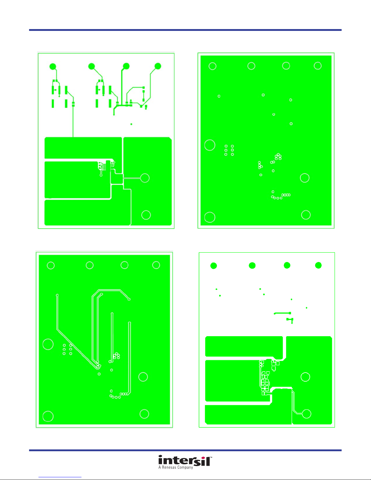
PCB Layout
FIGURE 3. TOP LAYER FIGURE 4. INNER LAYER 1
FIGURE 5. INNER LAYER 2 FIGURE 6. BOTTOM LAYER
AN1930 Rev.1.00 Page 5 of 5
Aug 28, 2014
Page 6

Mouser Electronics
Authorized Distributor
Click to View Pricing, Inventory, Delivery & Lifecycle Information:
Intersil:
ISL85003AEVAL2Z
 Loading...