

Page 1
®
ISL85001EVAL1Z: 1A
Regulator Standard Buck PWM
Description
The ISL85001EV AL1Z R EV A kit is intended fo r use by
individuals with requirements for Point-of-Load applications
sourcing fr om 4 .5V t o 2 5V. The ISL85001EVAL1Z evaluation
board is used to demonstrate the performance of the
ISL85001 standard buck regulator.
The ISL85001 is offered in a 4mmx3mm 12 Ld DFN package
with 1mm maximum height. The complete converter
occupies less than 0.425in
2
area.
Features
• Standard Buck Controller with Integrated Switching Power
MOSFET
• Integrated Boot Diode
• Input Voltage Range
- Fixed 5V ±10%
- Variable 5.5V to 25V
• PWM Output Voltage Adjustable from 0.6V to 19V with
Continuous Output Current up to 1A
• Voltage Mode Control with Voltage Feed-Forward
• Fixed 500kHz Switching Frequency
• Externally Adjustable Soft-Start Time
• Output Undervoltage Protection
• Enable Inputs
• PGOOD Output
• Overcurrent Protection
• Thermal Overload Protection
• Internal 5V LDO regulator
Applications
• General Purpose
• WLAN Cards-PCMCIA, Cardbus32, MiniPCI
Cards-Compact Flash Cards
• Hand-Held Instruments
• LCD Panel
• Set-top Box
December 1, 2008
AN1443.0Application Note
Recommended Equipment
The Following Materials are Recommended to Perform
Testing:
• 0V to 25V Power Supply with at Least 5A Source Current
Capability, Battery, Notebook AC Adapter
• One Electronic Load Capable of Sinking Current up to 5A
• Digital Multimeters (DMMs)
• 100MHz Quad-Trace Oscilloscope
• Signal Generator
Quick Setup Guide
1. Ensure that the circuit is correctly connected to the supply
and loads prior to applying any power.
2. Connect the bias supply to VIN, the plus terminal to TP1
(VIN) and the negative return to TP2 (GND).
3. Verify that SW1 is on ENABLE.
4. Turn on the power supply.
5. Verify the PG is on and the output voltage is 2.5V for
VOUT(TP3).
Evaluating the Other Output Voltage
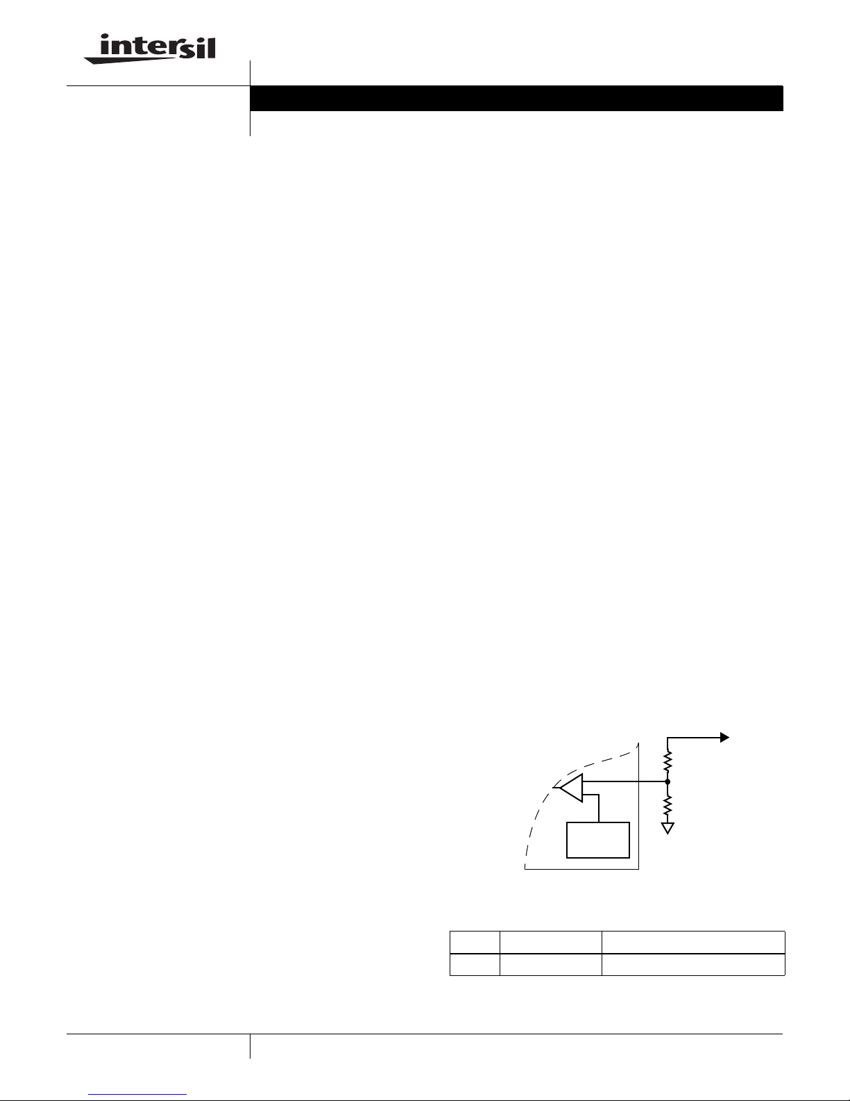
The ISL85001EVAL kit outputs are preset to 2.5V; however,
it can be programmed using resistor dividers using
Equation 1:
R10.6V⋅
----------------------------------
R
=
2
The output voltage programming resistor R
on the feedback resistor R
value of R
0.6V–
V
OUT
will depend on
, as referred to in Figure 1. The
is typically between 1kΩ and 10kΩ. If the output
1
1
2
voltage desired is 0.6V, then R2 is left opened.
R1
+
EA
REFERENCE
0.6V
R2
V
OUT
(EQ. 1)
What’s Inside
The Evaluation Board Kit contains the following materials:
• The ISL85001 EVAL REV A board
• The ISL85001 datasheet
• This EVAL KIT document
1
FIGURE 1. EXTERNAL RESISTOR DIVIDER
TABLE 1. SWITCH 1 SETTINGS
SW1 ENABLE OPERATING MODE
1 SW1 Enable or disable the buck controller
CAUTION: These devices are sensitive to electrostatic discharge; follow proper IC Handling Procedures.
1-888-INTERSIL or 1-888-468-3774
| Intersil (and design) is a registered trademark of Intersil Americas Inc.
All other trademarks mentioned are the property of their respective owners.
Copyright Intersil Americas Inc. 2008. All Rights Reserved
Page 2
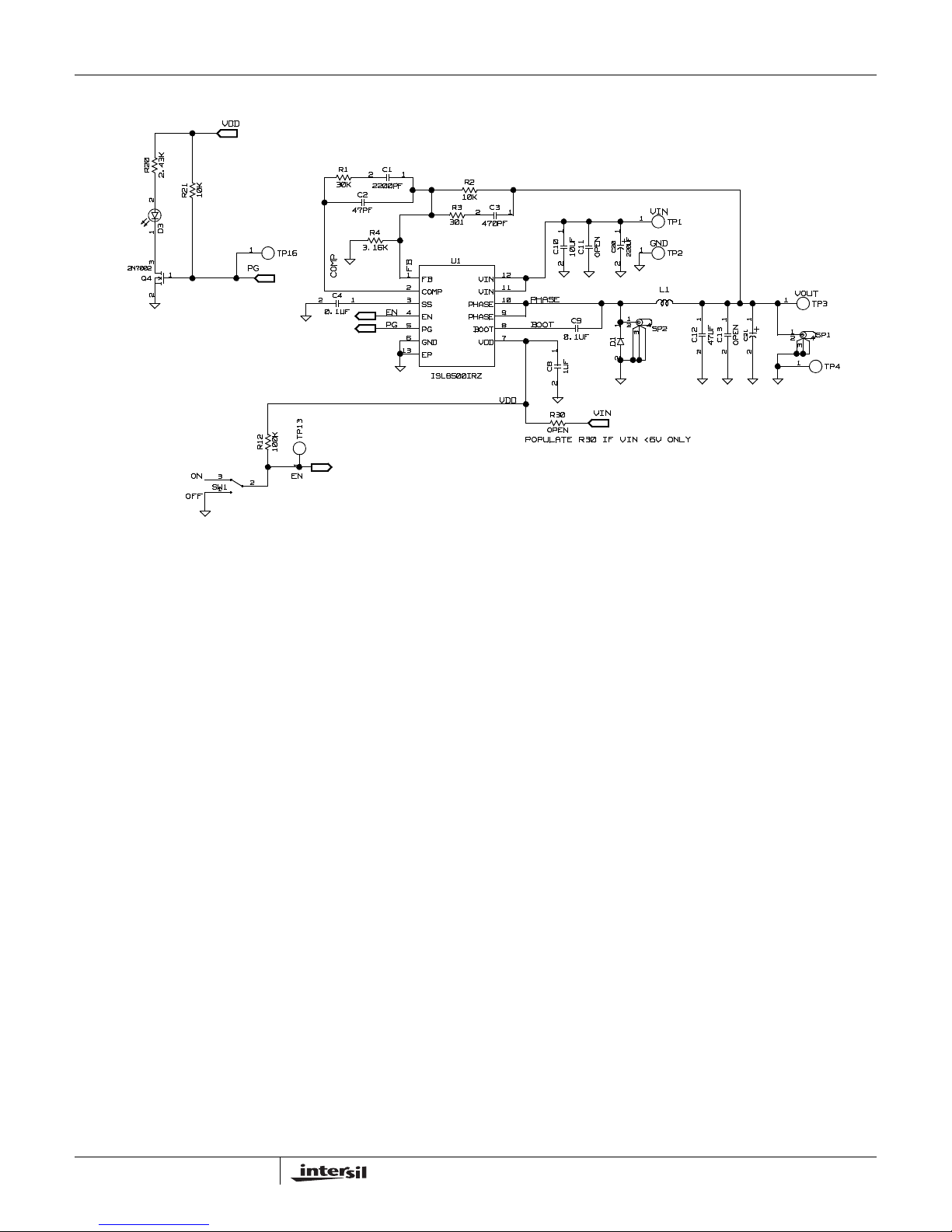
ISL85001EVAL1Z Schematic
VDD
Application Note 1443
2N7002
R20
2.43K
10K
R21
21
30K
D3
1
3
1
Q4
2
TP16
PG
C4
0.1UF
R1
COMP
C2
47PF
12
2
2200PF
R4
3.16K
C1
1
FB
1
2
3
EN
4
PG
5
67
13
FB
COMP
SS
EN
PG
GND
EP
ISL8500IRZ
301
R2
10K
C3
R3
U1
VIN
VIN
PHASE
PHASE
BOOT
VDD
470PF
12
12
C10
C11
10UF
OPEN
12
11
PHASE
10
9
8
BOOT
C8
12
C9
0.1UF
1UF
VIN
1
220UF
1
234
TP1
GND
1
TP2
SP2
L1
12
C21
C1312C12
47UF
OPEN
VOUT
1
1
234
1
TP3
SP1
TP4
1
2
12
C20
1
D1
2
VDD
VIN
R30
OPEN
POPULATE R30 IF VIN <6V ONLY
R12
100K
3
ON EN
OFF
SW1
2
1
TP13
1
2
AN1443.0
December 1, 2008
Page 3
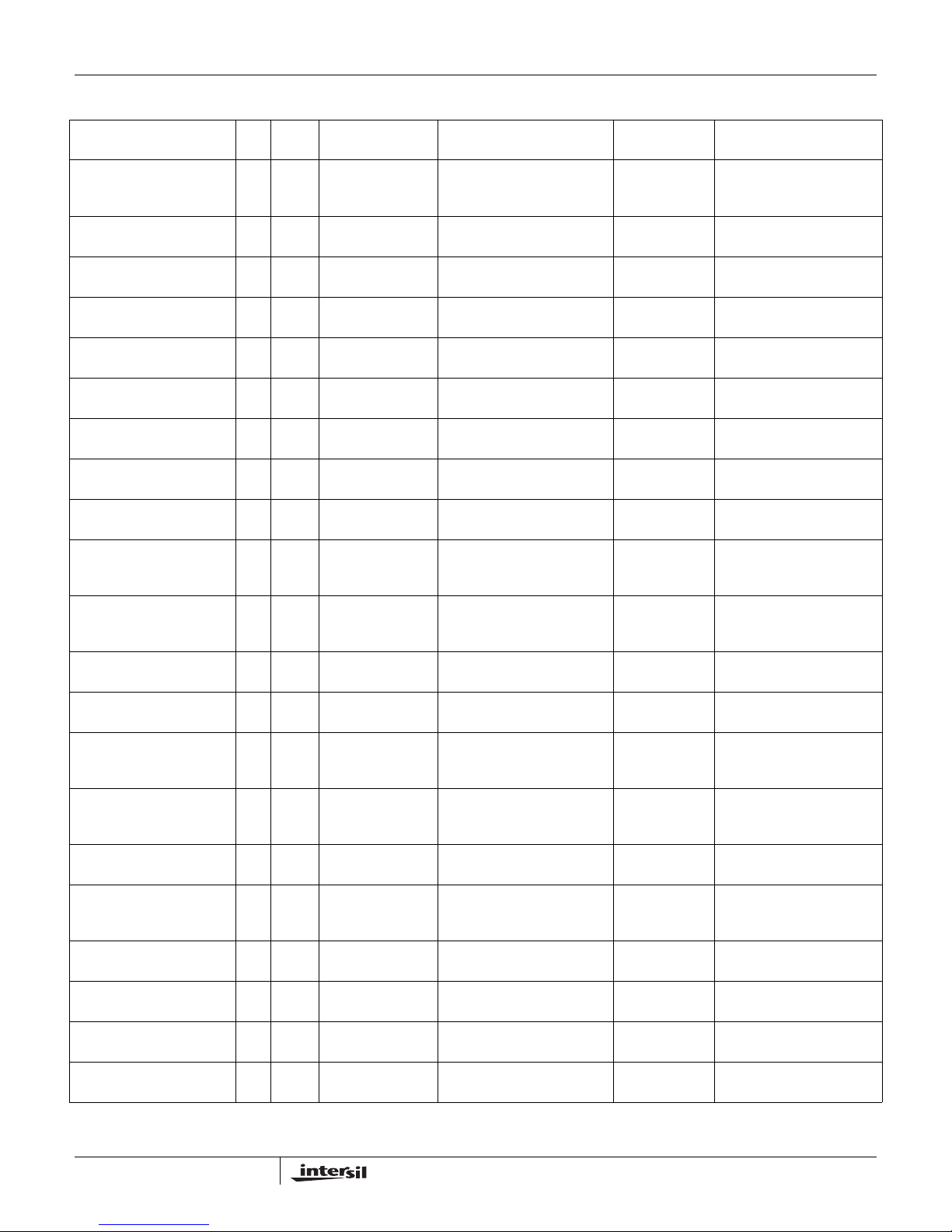
ISL85001EVAL1Z Bill of Materials
Application Note 1443
REFERENCE
PART NUMBER QTY UNITS
ISL85001EVAL1ZREVAPCB 1 ea See Label-Rename
C1608X7R1H104K-T 1 ea C9 CAPACITOR, SMD, 0603,
H1044-00104-16V10-T 1 ea C4 CAP, SMD, 0402, 0.1µF, 16V,
H1044-00222-50V10-T 1 ea C1 CAP, SMD, 0402, 2200pF,
H1044-00470-50V5-T 1 ea C2 CAP, SMD, 0402, 47pF, 50V,
H1044-00471-50V10-T 1 ea C3 CAP , SMD, 0402, 470pF, 50V ,
H1045-00105-6R3V10-T 1 ea C8 CAP, SMD, 0603, 1µF, 6.3V,
H1065-00106-25V10-T 1 ea C10 CAP, SMD,1206,10µF, 25V,
H1082-00476-16V20-T 1 ea C12 CAP, SMD, 1210, 47µF, 16V,
IHLP2525CZER220M11 1 ea L1 COIL-PWR INDUCTOR,
131-4353-00 2 ea SP1, SP2 CONN-SCOPE PROBE TEST
1514-2 4 ea TP1 to TP4 CONN-TURRET, TERMINAL
5002 2 ea TP13, TP16 CONN-MINI TEST POINT,
B340LB-13-F-T 1 ea D1 DIODE-SCHOTTKY, SMD,
LTST-C170CKT 1 ea D3 LED-GaAs RED, SMD,
ISL85001IRZ 1 ea U1 IC-2A BUCK REGULATOR,
2N7002-7-F-T 1 ea Q4 TRANSISTOR, N-CHANNEL,
H2510-01002-1/16W1-T 1 ea R2 RES, SMD, 0402, 10k, 1/16W,
H2510-01003-1/16W1-T 1 ea R12 RES, SMD, 0402, 100k,
H2510-03002-1/16W1-T 1 ea R1 RES, SMD, 0402, 30k, 1/16W,
H2510-03010-1/16W1-T 1 ea R3 RES, SMD, 0402, 301Ω,
DESIGNATOR DESCRIPTION MFR
Board
PWB-PCB,
ISL85001EVAL1Z, REVA,
ROHS
0.10µF, 50V, 10%, X7R
10%, X7R, ROHS
50V, 10%, X7R, ROHS
5%, NPO, ROHS
10%, X7R, ROHS
10%, X5R, ROHS
10%, X5R, ROHS
20%, x5R, ROHS
SMD, 6.9x6.5, 22µH, 20%,
7A, ROHS
PT, COMPACT, PCB MNT,
ROHS
POST, TH, ROHS
VERTICAL, WHITE, ROHS
SMB, 2P, 40V, 3A LOW VF,
ROHS
2x1.25mm,100mW, 40mA,
10mcd, ROHS
12P, DFN, 4x3, ROHS
3LD, SOT-23, 60V, 115mA,
ROHS
1%, TF, ROHS
1/16W, 1%, TF, ROHS
1%, TF, ROHS
1/16W, 1%, TF, ROHS
MANUFACTURER
PART
TITAN ISL85001EVAL1ZREVAPCB
TDK C1608X7R1H104K
MURATA GRM36X7R104K016AD
PANASONIC ECJ-0EB1H222K
MURATA GRM36COG470J050AQ
PANASONIC ECJ-0EB1H471K
PANASONIC ECJ1VB0J105K
VENKEL C1206X5R250-106KNE
TDK C3225X5R1C476M
VISHAY IHLP2525CZER220M11
TEKTRONIX 131-4353-00
KEYSTONE 1514-2
KEYSTONE 5002
DIODES INC. B340LB-13-F
LITEON/VISHAYLTST-C170CKT
INTERSIL ISL85001IRZ
DIODES,INC. 2N7002-7-F
PANASONIC ERJ-2RKF1002
PANASONIC ERJ2RKF1003
YAGEO RC0402FR-0730KL
PANASONIC ERJ-2RKF3010X
3
AN1443.0
December 1, 2008
Page 4
Application Note 1443
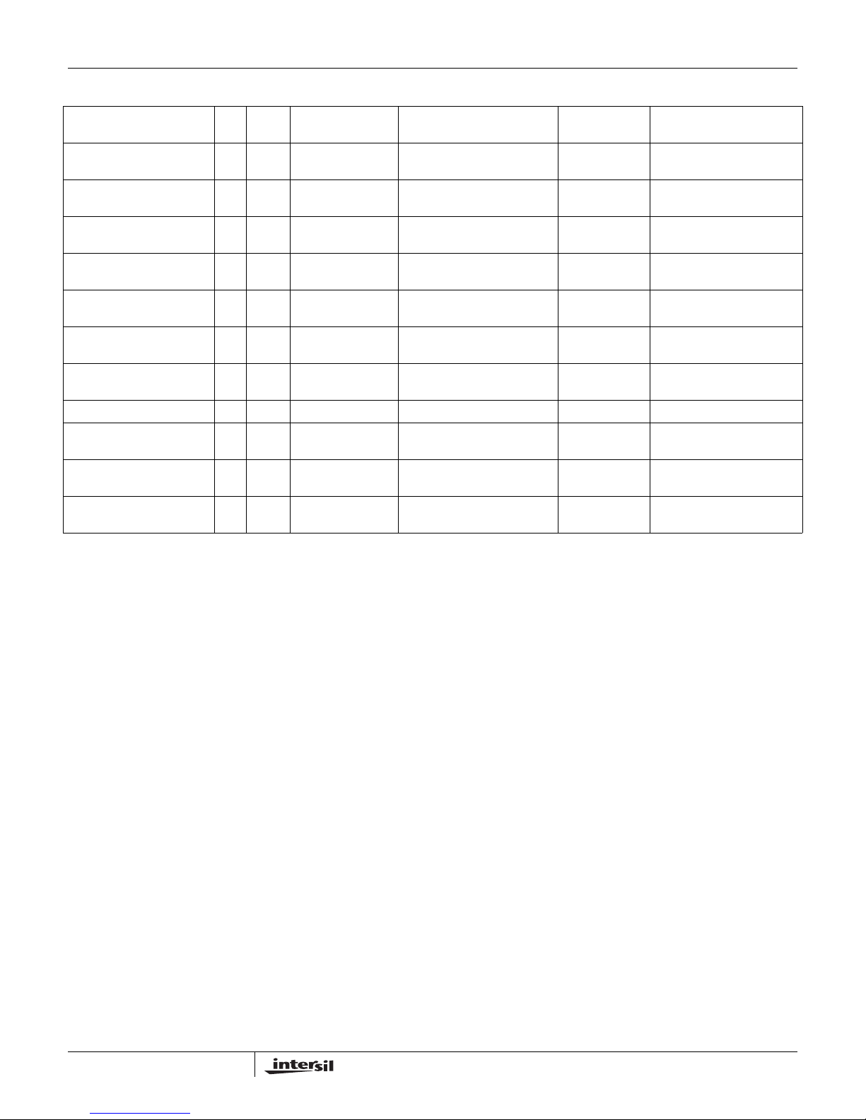
ISL85001EVAL1Z Bill of Materials (Continued)
REFERENCE
PART NUMBER QTY UNITS
H2510-03161-1/16W1-T 1 ea R4 RES, SMD, 0402, 3.16k,
H2511-01002-1/10W1-T 1 ea R21 RES, SMD, 0603, 10k, 1/10W,
H2511-02431-1/10W1-T 1 ea R20 RES, SMD, 0603, 2.43k,
H2511-DNP 0 ea R30 RES, SMD, 0603, DNP-
GT11MSCBE-T 1 ea SW1 SWITCH-TOGGLE, SMD,
4-40x1/2-SCREW 4 ea Four corners SCREW, 4-40x1/2in, PAN,
4-40x3/4-STANDOFF 4 ea Four corners STANDOFF, 4-40x3/4in, F/F,
5x8-STATIC-BAG 1 ea Place assy in bag. BAG, STATIC, 5x8, ZIP LOC INTERSIL 212403-013
DNP 0 ea C11, C13, C20, C21 DO NOT POPULATE OR
LABEL-RENAME BOARD 1 ea RENAME PCB TO:
LABEL-SERIAL NUMBER 1 ea LABEL, FOR SERIAL
DESIGNATOR DESCRIPTION MFR
VENKEL CR0402-16W-3161FT
1/16W, 1%, TF, ROHS
1%, TF, ROHS
1/10W, 1%, TF, ROHS
PLACE HOLDER, ROHS
ULTRAMINI, 1P, SPST MINI
NYLON, PHILLIPS, ROHS
HEX, NYLON
PURCHASE
LABEL, TO RENAME BRD
ISL85001EVAL1Z
NUMBER AND BOM REV #
KOA RK73H1JT1002F
VENKEL CR0603-10W-2431FT
C&K
COMPONENTS
KEYSTONE 1902D
MANUFACTURER
GT11MSCKE
PART
4
AN1443.0
December 1, 2008
Page 5
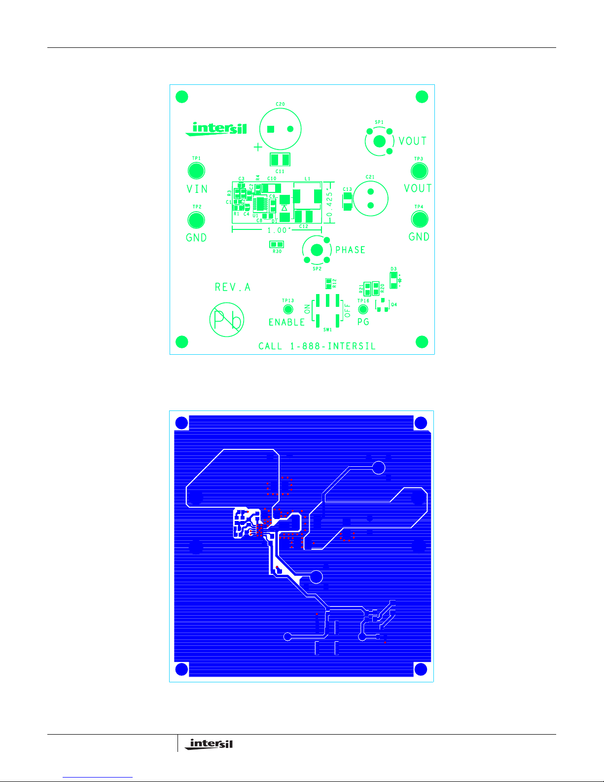
ISL85001EVAL1Z Board Layout
ISL85001EVAL1Z
Application Note 1443
FIGURE 2. TOP COMPONENTS
5
FIGURE 3. TOP LAYER ETCH
AN1443.0
December 1, 2008
Page 6
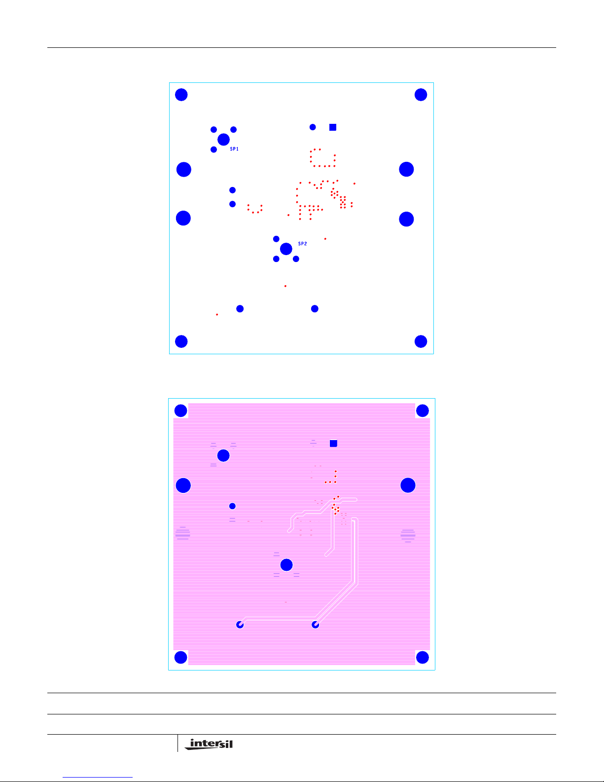
Application Note 1443
ISL85001EVAL1Z Board Layout (Continued)
FIGURE 4. BOTTOM LAYER COMPONENTS (MIRRORED)
Intersil Corporation reserves the right to make changes in circuit design, software and/or specifications at any time without notice. Accordingly, the reader is cautioned to
verify that the Application Note or Technical Brief is current before proceeding.
For information regarding Intersil Corporation and its products, see www.intersil.com
6
FIGURE 5. BOTTOM LAYER ETCH (MIRRORED)
AN1443.0
December 1, 2008
 Loading...