

Page 1
Application Note 1657
Author: Xiaoying Shi
ISL76683 Light-to-Digital Output Sensor Evaluation
Hardware/Software User Guide
Description
The ISL76683EVAL1Z evaluation board is an RoHS compliant
evaluation board designed for exploring the operation of the
ISL76683 light-to-digital output sensor. The evaluation board is
an easy-to-use platform for testing most of the specifications
and functionalities described in the ISL76683 datasheet
.
Evaluation Package
• Demo Board (Evaluation Board ISL76683EVAL1Z and USB
Board ISLUSBCEVAL1Z, REV A), populated with all required
components
•USB 2.0 Cable
• Evaluation Software (see “Tools and Support”
device information page)
• AN1657: “ISL76683 Light-to-Digital Output Sensor
Evaluation Hardware/Software User Guide” (see “Technical
Documentation” on ISL76683 device information page)
on ISL76683
System Requirements
• Windows 98/NT/2000/XP
•USB Port
Hardware Setup
The PC and printed circuit board (PCB) should not be
connected via the USB until after the evaluation software has
been installed satisfactorily (see “Software Setup” on page 2).
To set up the hardware:
1. Connect the USB 2.0 cable first to the PC and then to the
evaluation board. The USB cable is the only connector
needed.
2. If a dialog appears asking about installing software for
new-found hardware, click “Yes, this time only”.
The jumpers on the printed circuit board (PCB) are as shown in
Table 1.
TAB LE 1. JUMPER S ON PCB
JUMPER DESCRIPTION
J500K Rext = 500
J100K Rext = 100kΩ (Default)
J50K Rext = 50
VDD to 3.3V Connect 3.3V rail to VDD
kΩ
kΩ
August 12, 2011
AN1657.0
1
1-888-INTERSIL or 1-888-468-3774
CAUTION: These devices are sensitive to electrostatic discharge; follow proper IC Handling Procedures.
| Intersil (and design) is a trademark owned by Intersil Corporation or one of its subsidiaries.
All other trademarks mentioned are the property of their respective owners.
Copyright Intersil Americas Inc. 2011. All Rights Reserved.
Page 2
Software Setup
Application Note 1657
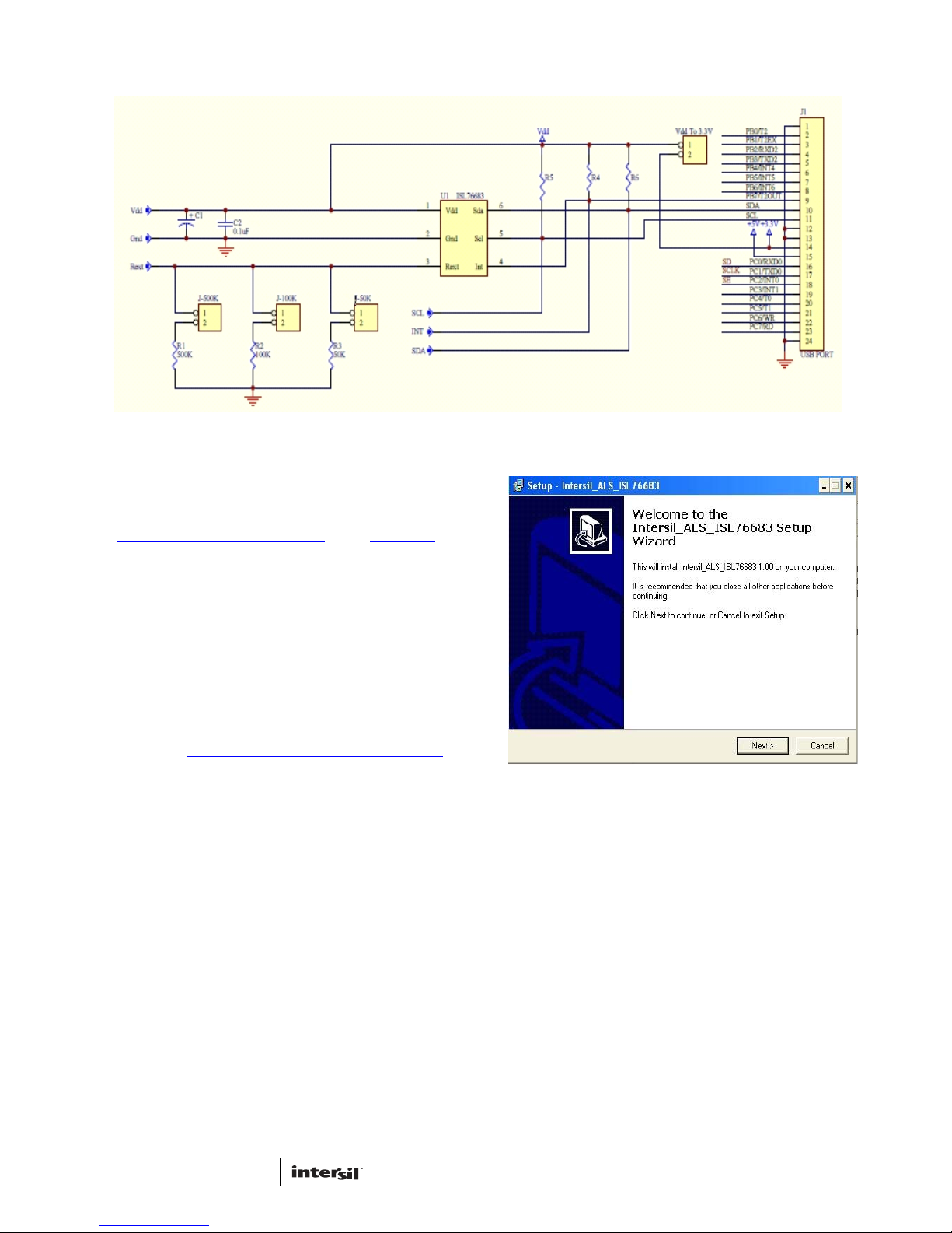
FIGURE 1. ISL76683EVAL1Z EVALUATION BOARD SCHEMATIC
Downloading the Software
On the ISL76683 device information page, under “Tools and
Support”, click Intersil_ALS_ISL76683_Installer_V100.exe to
download the ISL76683 evaluation software installer file.
Firmware Reference
The installer file has Human Interface Device (HID) firmware in
the microcontroller board, ISLUSBCEVAL1Z, REV A. The firmware
allows the evaluation software to communicate with the
ISL76683 evaluation board through a PC operating on Windows
98/NT/2000/XP.
Installing the Software
Download and run Intersil_ALS_ISL76683_Installer_V100.exe.
The dialog shown in Figure 2 appears. Follow the instructions on
each screen for installing the software. The PC and PCB should
not be connected via the USB until after the installation has
completed satisfactorily.
FIGURE 2. SOFTWARE SETUP WIZARD
2
AN1657.0
August 12, 2011
Page 3
Application Note 1657
Running the Evaluation Software
To open the evaluation software program:
1. Click the Start menu and navigate to the software as follows:
Start -> All Programs -> Intersil -> Intersil_ALS_ISL76683 ->
Intersil_ALS_ISL76683.
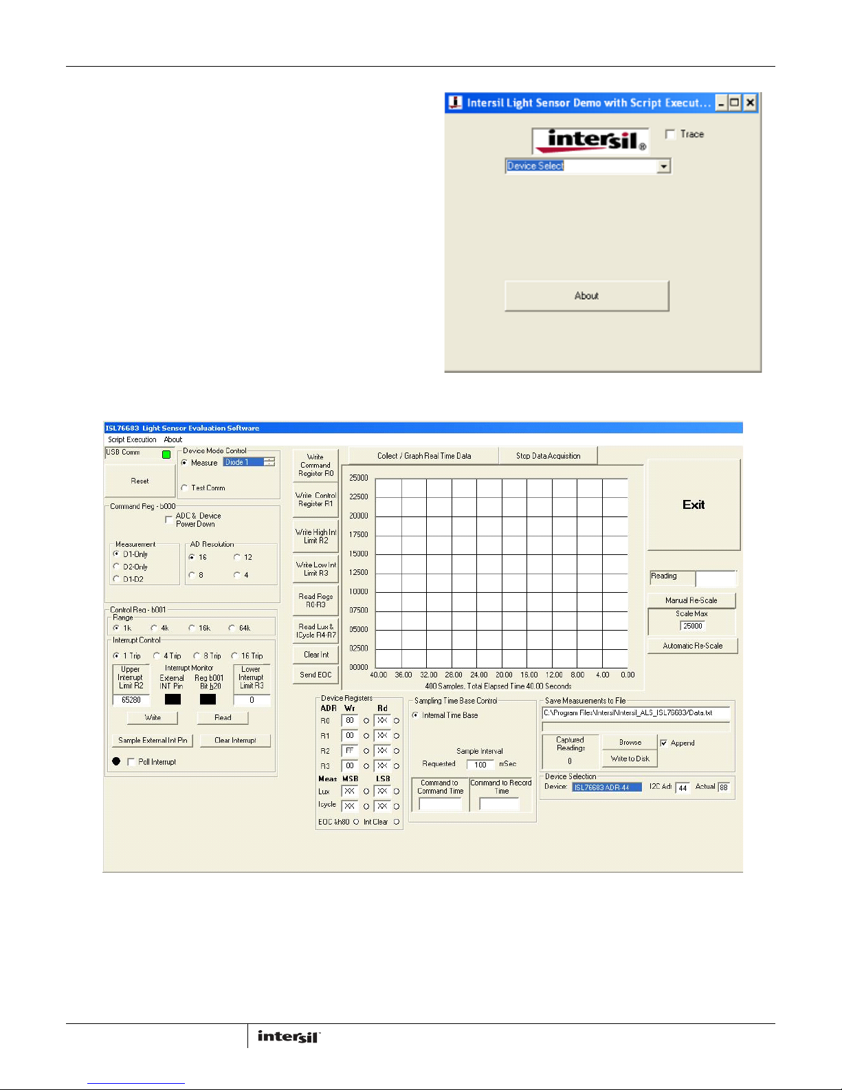
2. Double-click the program name. The Intersil Light Sensor
Demo... window shown in Figure 3 appears.
3. In the Device Select dropdown menu, select ISL76683.
4. The ISL76683 Light Sensor Evaluation Software window
shown in Figure 4 opens. This window is the main interface for
demonstrating the capabilities of ISL76683.
FIGURE 3. SOFTWARE STARTUP
FIGURE 4. ISL76683 LIGHT SENSOR EVALUATION SOFTWARE USER INTERFACE
3
AN1657.0
August 12, 2011
Page 4
Application Note 1657
Using the ISL76683 Light Sensor
Evaluation Software
USB Communications
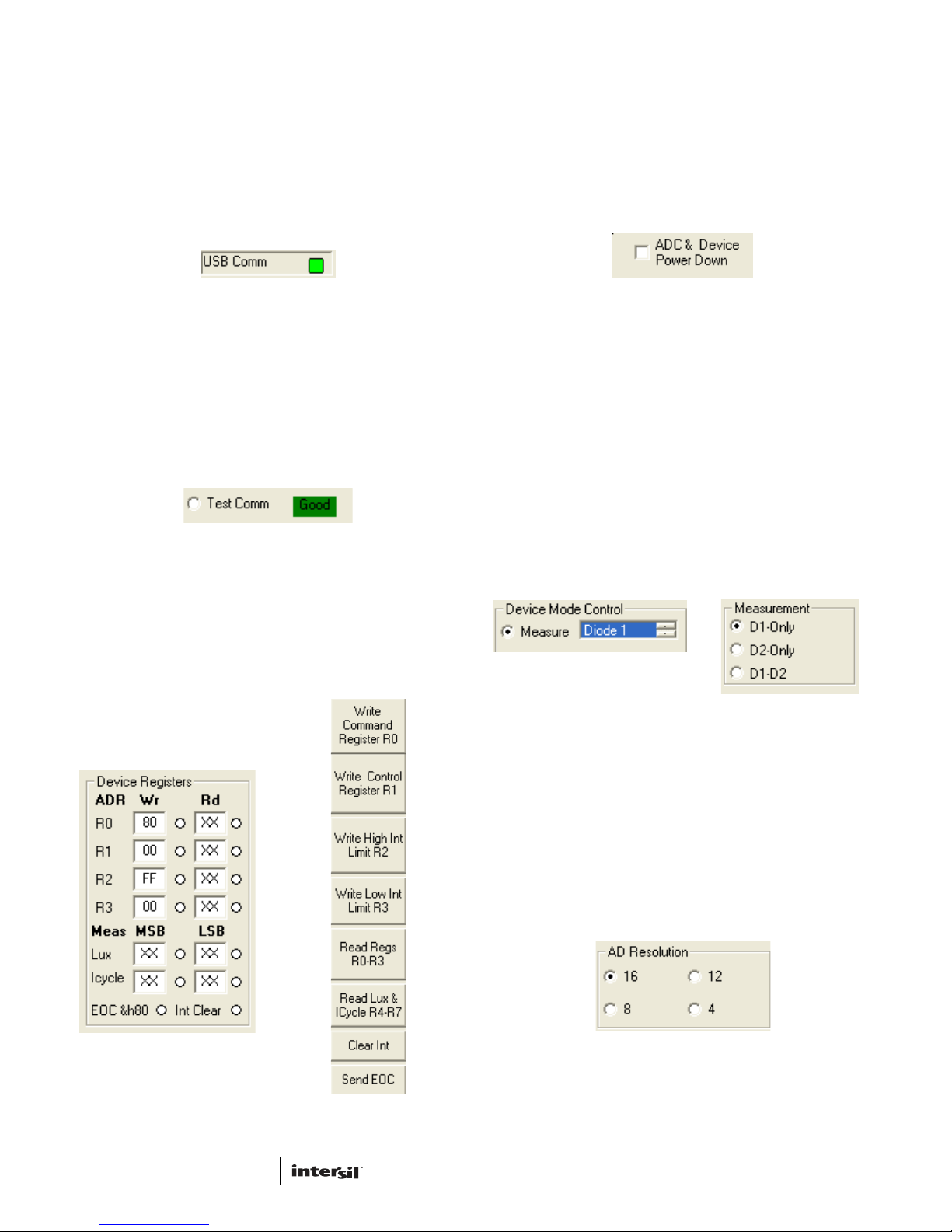
In the upper left corner of the ISL76683 Light Sensor Evaluation
Software window, in the USB Comm area, ensure that the light is
green (Figure 5). If it is not green, check the USB cable
connection.
FIGURE 5. USB COMMUNICATIONS INDICATOR
Test Communications
In the upper left corner of the ISL76683 Light Sensor Evaluation
Software window, in the Device Mode Control dialog area, click
the Test Comm radio button to test communications between the
PC and the evaluation board. If it shows Good, as shown in
Figure 6, then the hardware and software are properly set up. If it
shows Fail, check the connections between the PC and the
board. If the problem persists, restart the software.
FIGURE 6. TEST COMMUNICATIONS
Device Registers
The Device Registers area (Figure 7) in the bottom center of the
ISL76683 Light Sensor Evaluation Software window displays the
current state of the device registers (Figure 7A). Use the column
of buttons to the left of the Collect/Graph Real Time Data grid
(top center) (Figure 7B) to read or write to the registers.
Command Register 00 (Hex)
ADC RESET AND DEVICE POWER-DOWN
In the upper left corner of the ISL76683 Light Sensor Evaluation
Software window, in the Command Reg - b000 dialog area, click
the ADC & Device Power Down check box to disable and reset the
ADC and to put the ISL76683 into power-down mode.
FIGURE 8. ADC RESET AND DEVICE POWER-DOWN
MEASUREMENT MODE SELECTION
The ISL76683 contains two photodiodes. Diode 1 is sensitive to
both visible and infrared light, while Diode 2 is sensitive mostly to
infrared light. Measurement Mode 1 is Diode 1 only, and
Measurement Mode 2 is Diode 2 only. Measurement Mode 3 is a
sequential Mode 1 and Mode 2, with an internal subtract
function (Diode 1 - Diode 2).
You can select the measurement mode in one of two ways. In the
upper left corner of the ISL76683 Light Sensor Evaluation
Software window, in the Device Mode Control dialog area, click
the Measure radio button, and from the scroll list, select the
diode to be measured (Figure 9A). Or, in the Command Reg b000 dialog area, under Measurement, click one of three radio
buttons to select the diode to measure (Figure 9B).
FIGURE 9A.
FIGURE 9. MEASUREMENT MODE SELECTION
FIGURE 9B.
FIGURE 7A.
FIGURE 7. DEVICE REGISTERS STATUS, READ, AND WRITE
4
FIGURE 7B.
AD RESOLUTION
Changing the number of clock cycles does more than just change
the resolution of the device; it also changes the integration time,
which is the period the device’s analog-to-digital converter (ADC)
samples the photodiode current signal for a lux measurement. To
change the device resolution (and integration time), in the
Command Reg - b000 dialog area, under AD Resolution, click
one of the four radio buttons to select the number of clock cycles
per conversion.
FIGURE 10. AD RESOLUTION SELECTION
AN1657.0
August 12, 2011
Page 5
Application Note 1657
Control Register 01 (Hex)
RANGE/GAIN SELECTION
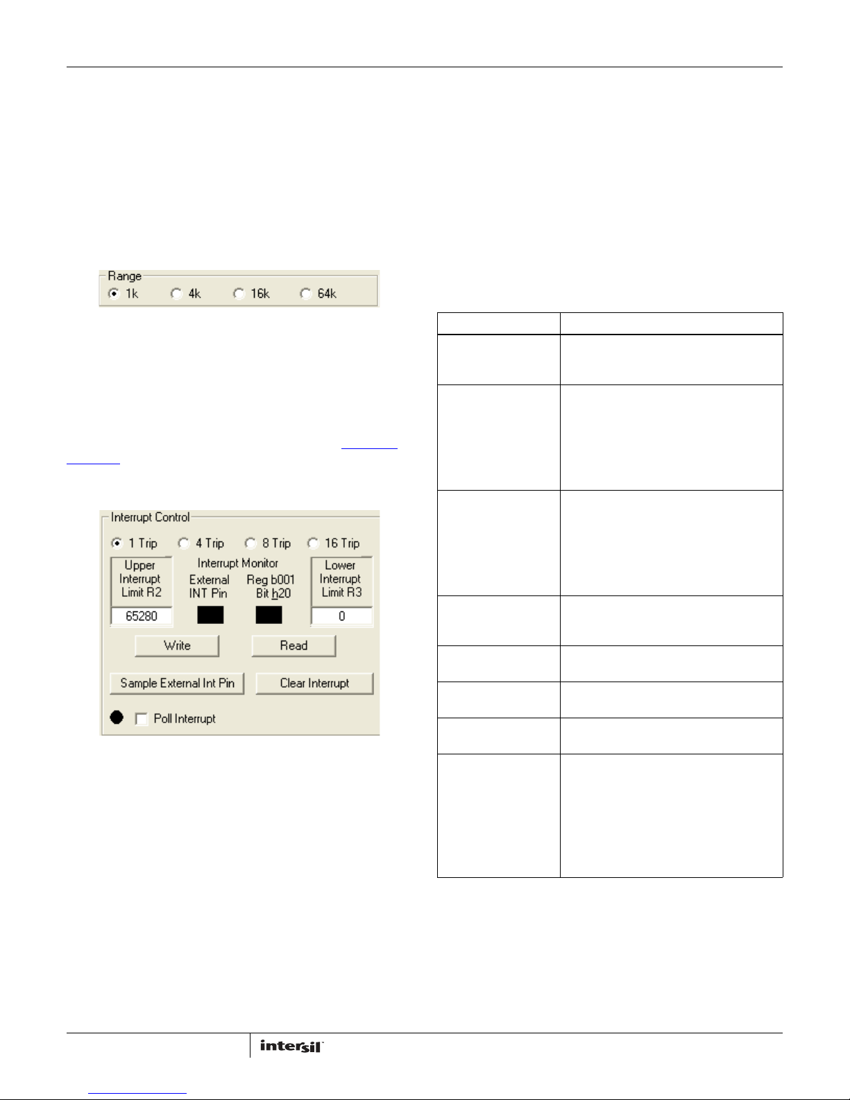
The ADC has four I2C programmable range (gain) selections to
dynamically accommodate various lighting conditions. For
example, a very bright object requires a higher range (e.g., 64k)
than a dark object, which requires a low range (e.g., 1k). Higher
ranges reduce photo detector sensitivity. In the ISL76683 Light
Sensor Evaluation Software window, in the Control Reg - b001
dialog area, under Range, click one of the four radio buttons to
select the range to match lighting conditions.
FIGURE 11. RANGE/GAIN SELECT
Interrupt Control Register 01 (Hex) and
Threshold Registers 02 (Hex) and 03 (Hex)
Interrupt thresholds are stored in Registers 0x02 and 0x03. In
the Interrupt Control dialog (Figure 12), enter values in the Upper
Interrupt Limit R2 and Lower Interrupt Limit R3 text boxes and
click Write to edit the interrupt thresholds. (See the ISL76683
datasheet for more information on interrupt limits.) The interrupt
thresholds act as an alarm or monitoring function to determine
whether the ADC count exceeds the upper or lower limit.
FIGURE 12. INTERRUPT CONTROL
To set the interrupt limits in the Interrupt Control dialog (see
Table 2 for parameter descriptions):
1. Click one of the four radio buttons across the top of the dialog
window to choose an interrupt persistence value
(recommended value: 8 Trip).
2. Enter decimal values in the Upper Interrupt Limit R2 and
Lower Interrupt Limit R3 text boxes. The upper limit must be
greater than the lower limit. Values for the limits depend on
the application, the configuration of other options, and the
distance at which you choose to flag.
3. Click Write and then click Read. Verify the desired limit values
by comparing the values entered for the intended limits to the
values in the Device Registers dialog after clicking Read. If
they do not match, repeat Steps 2 and 3.
4. Click Clear Interrupt to clear or reset the interrupt status bit.
5. You can manually poll the Interrupt pin (Pin 4 on the
ISL76683EVAL1Z evaluation board) or you can set it to be
polled automatically. To poll it manually, click Sample
External Int Pin. To poll it automatically, click the Poll Interrupt
check box to select it.
With interrupt limits set, you can begin collecting data. Data is
collected within the upper and lower limits you selected. In the
Interrupt Control dialog, in the Interrupt Monitor area, black
boxes indicate an unflagged status that is within limits. Red
boxes indicate the data collected is either above the upper limit
or below the lower limit and that the interrupt flag has been
triggered.
TABLE 2. INTERRUPT CONTROL PARAMETERS
PARAMETER DESCRIPTION
Interrupt Persistence Sets the number of times the upper limit is
exceeded or lower limit is subceeded before
an alarm or interrupt flag is raised.
Upper Interrupt Limit R2 Applies to Interrupt Threshold HI Register
0x02. This register sets the HI threshold for the
Interrupt pin and the interrupt flag. By default,
the interrupt threshold HI is FF (hex). The 8-bit
data written to the register represents the
upper MSB of a 16-bit value. The LSB is always
00 (hex).
Lower Interrupt Limit R3 Applies to Interrupt Threshold LO Register
0x03. This register sets the LO threshold for
the Interrupt pin and the interrupt flag. By
default, the Interrupt threshold LO is 00 (hex).
The 8-bit data written to the register
represents the upper MSB of a 16-bit value.
The LSB is always 00 (hex).
Write, Read Store or read values in the upper and lower
interrupt limit threshold Registers 0x02 and
0x03.
Clear Interrupt Click Clear Interrupt to clear or reset the
interrupt status bit.
Sample External Int Pin Manually sample the external interrupt pin
(Pin 4) on the IC.
Poll Interrupt Allows checking of the external interrupt
status while sampling data.
Interrupt Monitor • Square indicator light displays status:
black means no fault; red means an
interrupt fault.
• Monitor external interrupt pin manually by
clicking Sample External Int Pin button or
automatically by clicking Poll Interrupt
check box to select it. Reg b001, Bit h20,
can only be monitored manually.
5
AN1657.0
August 12, 2011
Page 6
Application Note 1657
Data Collection
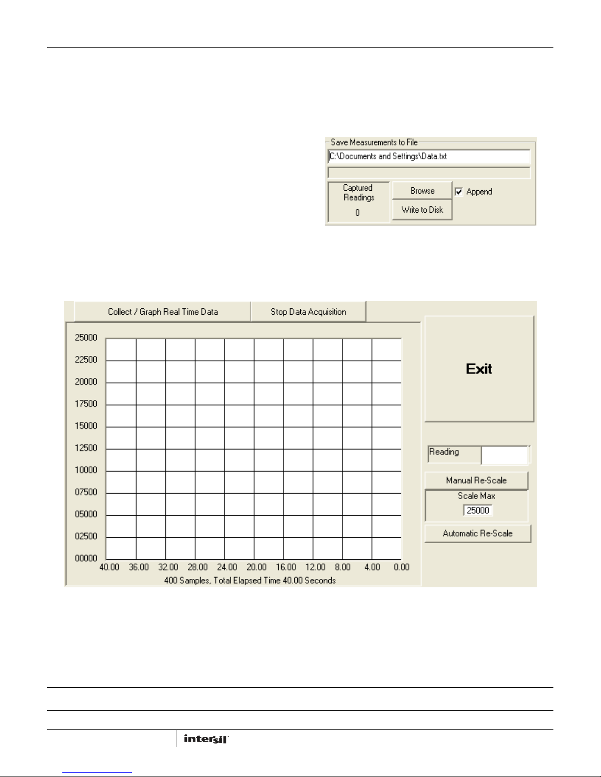
In the ISL76683 Light Sensor Evaluation Software window, use
the Collect/Graph Real Time Data dialog (Figure 13) to acquire
and graph measurements.
•Click Collect/Graph Real Time Data to sample data. Samples
are taken and plotted, and values are displayed in the Reading
field on the right side of the dialog. The Reading field displays
the value of the ADC output coming out of the sensor in
accordance with the mode that is engaged.
•Click Stop Data Acquisition to stop data sampling.
•Click Exit to close the entire program.
•In the Scale Max text box, enter a maximum value for the scale
(vertical axis), and click Manual Re-Scale to re-set.
•Click Automatic Re-Scale to re-scale the vertical axis to an
appropriate field of view. This feature is useful if the sampled
data is out of the range of the graph or if you need to zoom in
on the data.
Saving Measurements to File
Use the Save Measurements to File dialog box in the lower right
corner of the ISL76683 Light Sensor Evaluation Software window
to save a series of measurements to disk. Click Browse to enter a
filename and select a file path. Click Write to Disk to write the
current graph data to disk.
FIGURE 14. SAVE MEASUREMENTS TO FILE
Intersil Corporation reserves the right to make changes in circuit design, software and/or specifications at any time without notice. Accordingly, the reader is
cautioned to verify that the Application Note or Technical Brief is current before proceeding.
For information regarding Intersil Corporation and its products, see www.intersil.com
6
FIGURE 13. GRAPHICAL REAL-TIME DATA COLLECTION
AN1657.0
August 12, 2011
 Loading...