

Page 1
®
Using the ISL6443AEVAL2Z Evaluation Board
Application Note March 10, 2008
Using the Evaluation Board
The ISL6443A is a high performance triple-output controller
offering control and protection features for 2 synchronous
buck PWMs and 1 linear regulator.
The ISL6443A evaluation board highlights the operation of
the IC in an embedded DC/DC converter application. Table 1
shows the available evaluation board.
TABLE 1. EVALUATION BOARDS
BOARD NAME IC PACKAGE
ISL6443AEVAL2Z ISL6443AIRZ 28 Ld QFN
Recommended Test Equipment
• A 12V, 5A capable power supply
• An electronic load
• Four channel oscilloscope with probes
• Precision digital multimeters
Power and Load Connections
Input Voltage
To connect a +12V power supply to the evaluation board,
connect the positive lead of the power supply to the VIN (P1)
post and the ground lead of the supply to the GND (P2) post.
AN1391.0
Power Good
When both PWMs are within ±10% of their set value and the
linear regulator output is within 75% of its set value, the
PGOOD signal will go high. The open drain PGOOD pin is
pulled HIGH to VCC_5V on the board. The PGOOD circuitry
monitors the FBx pin of each regulated output to determine if
the outputs are in regulation. PGOOD can be monitored at
post P8.
Overcurrent Protection
The overcurrent thresholds can be adjusted on the
ISL6443A evaluation board. The current sense resistors,
I
, are set at 1.0kΩ. The overcurrent set resistor is
SENSE
95.3kΩ. The overcurrent trip point can be adjusted by
modifying R
R
OCSET
R
OCSET
=
is the overcurrent set resistor, R
sense resistor, I
r
is the ON-resistance of the respective PWM’s lower
DS(ON)
MOSFET. Refer to the ISL6443A Data Sheet for more
information on how to select the current sense and
overcurrent select resistors.
, R5 and R10:
OCSET
7RCS⋅
-------------------------------------
I
⋅
OCrDS ON()
is the desired overcurrent trip point, and
OC
CS
(EQ. 3)
is the current
The input voltage to the linear controller is already taken
from the 1.8V output of V
OUT2.
Output Adjustment
Change the respective output voltage feedback resistors to
modify the output voltage using Equation 1:
V
OUT1
V
OUT3
R
⎛⎞
0.8 1
0.8 1
-------
+
⋅=
⎜⎟
R
⎝⎠
⎛⎞
--------- -
+
⋅=
⎜⎟
R
⎝⎠
1
2
R
6
11
V
OUT2
0.8 1
R
⎛⎞
3
-------
+
⋅=
⎜⎟
R
⎝⎠
4
(EQ. 1)
Soft-Start and Shutdown
The soft-start capacitors can be adjusted for sequencing of
the output voltages, PWM start-up tracking, and/or to adjust
the start-up current required to charge the output capacitors.
0.8V
------------
t
SS PWM1()C2
⋅= t
5μ A
SS PWM2()C3
To independently shutdown the PWMs, the SD1 or SD2 pin
can be pulled to GND using the on-board posts, P9 and P10
respectively.
0.8V
------------
⋅=
5μ A
(EQ. 2)
1
CAUTION: These devices are sensitive to electrostatic discharge; follow proper IC Handling Procedures.
1-888-INTERSIL or 1-888-468-3774
| Intersil (and design) is a registered trademark of Intersil Americas Inc.
All other trademarks mentioned are the property of their respective owners.
Copyright Intersil Americas Inc. 2008. All Rights Reserved
Page 2
2
AN1391.0
March 10, 2008
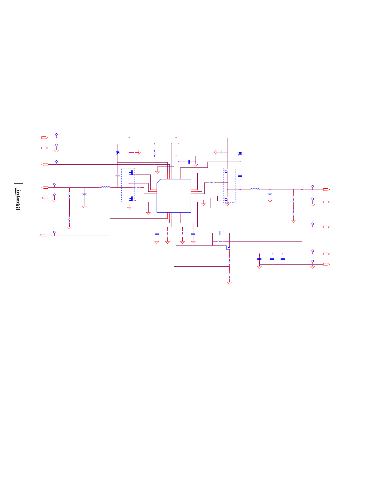
ISL6443AEVAL2Z Schematic
+1.8V, 2A
+3.3V, 2A
PGOOD
+1.2V, 0.2A
+12V
GND
GND
GND
SD1
SD2
GND
C21
10uF
C21
10uF
P6
GNDP6GND
C34
DNP
C34
DNP
R12
5.11k
R12
5.11k
P8
GNDP8GND
C3
0.01uFC30.01uF
Q3
IRLML6401Q3IRLML6401
L1
6.8uH, 27mOhm
DO3316P-682ML
L1
6.8uH, 27mOhm
DO3316P-682ML
L2
6.8uH, 27mOhm
DO3316P-682ML
L2
6.8uH, 27mOhm
DO3316P-682ML
R2
324R2324
Q1A
FDS6912A
Q1A
FDS6912A
R11KR1
1K
C4
10uFC410uF
P7
+1.2VP7+1.2V
C33
DNP
C33
DNP
R31kR3
1k
C2
0.01uFC20.01uF
C30
220uF, 10V, 40mOhm
10TPB220M
C30
220uF, 10V, 40mOhm
10TPB220M
R71kR7
1k
C6
1uFC61uF
R8
100R8100
P9
SD1P9SD1
P11
PGOOD
P11
PGOOD
P3
+3.3VP3+3.3V
D1
BAT54HT1D1BAT54HT1
C7
0.1uFC70.1uF
R112kR11
2k
C5
0.1uFC50.1uF
P4
GNDP4GND
R61kR6
1k
C1
4.7uFC14.7uF
R10
95.3k
R10
95.3k
C20
10uF
C20
10uF
Q2A
FDS6912A
Q2A
FDS6912A
Q2BQ2B
C31
220uF, 10V, 40mOhm
10TPB220M
C31
220uF, 10V, 40mOhm
10TPB220M
C32
10uF
C32
10uF
R4
806R4806
P2
GNDP2GND
R5
95.3kR595.3k
P1
+12VP1+12V
U1
ISL6443AIRZU1ISL6443AIRZ
UGATE1
23
PHASE1
22
ISEN1
21
LGATE1
25
PGND
20
FB1
15
SGND
14
SD119SS118OCSET116FB312GATE313OCSET27SS2
6
SD2
5
SGND
9
FB2
8
LGATE2
26
ISEN2
2
PHASE2
1
UGATE2
28
BOOT2
27
VCC_5V
4
VIN
10
SGND
17
SYNC
11
PGOOD
3
BOOT1
24
SGND
29
P10
SD1
P10
SD1
Q1BQ1B
R91kR9
1k
P5
+1.8VP5+1.8V
D2
BAT54HT1D2BAT54HT1
Application Note 1391
Page 3
Application Note 1391
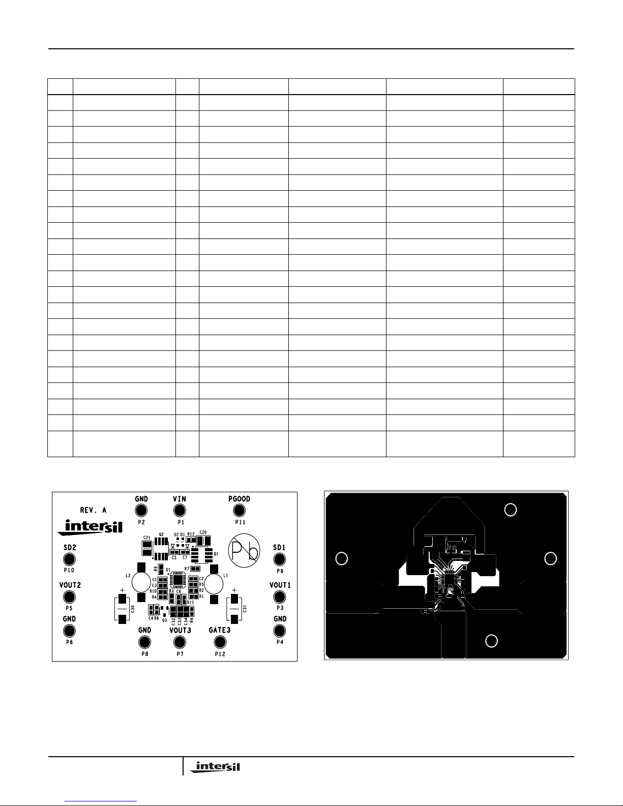
ISL6443AEVAL2Z Bill of Materials
ITEM REFERENCE QTY PART NUMBER PART TYPE DESCRIPTION VENDOR
1 P1 to P12 12 1514-2 Test Point Turret 0.281 Height Keystone
2 D1, D2 2 BAT54HT1G Diode, Schottky 30V, 200mA On Semi
3 C4 1 C1608X5R0J106 Cap, Ceramic, X5R 10µF, 6.3V, 0603, X5R TDK
4 C30, C31 2 10TPB220M Cap, POSCAP 220µF, 10V Panasonic
5 C20, C21 2 C3225X5R1C106KT Cap, Ceramic, 1210 10µF, 16V, 1210, X5R TDK
6 L1, L2 2 DO3316P-682ML SMT Power Inductor 6.8µH, ±20%, 4.6A, 27mΩ Coilcraft
7 C1 1 Capacitor , Ceramic, 0603 4.7 µF, 20%, 6.3V, 0603 Generic
8 Q1, Q2 2 FDS6912A Dual NFET 6A, 30V, Dual NFET, SO8 Fairchild
9 C5, C7 2 Cap, Ceramic, 0603 0.1µF, 10%, 16V Generic
C2, C3 2 Cap, Ceramic, 0603 0.01µF, 10%, 16V Generic
10 C6 1 Ca p, C e r a mi c , 0 6 03 1.0µF, 10%, 16V Generic
11 C32 1 Cap, Ceramic, 0805 10µF, 10%, 6.3V Generic
12 C33, C34 2 NOT POPULATED 13 R8 1 Resistor, Film 100Ω, 0603, 1%, 1/16W Generic
14 R1, R3, R6, R7, R9 5 Resistor, Film 1kΩ, 0603, 1%, 1/16W Generic
15 R11 1 Resistor, Film 2kΩ, 0603, 1%, 1/16W Generic
16 R2 1 Resistor, Film 324Ω, 0603, 1%, 1/16W Generic
17 R5, R10 1 Resistor, Film 95.3kΩ, 0603, 1%, 1/16W Generic
18 R12 1 Resistor, Film 5.11kΩ, 0603, 1%, 1/16W Generic
19 R4 1 Resistor, Film 806Ω, 0603, 1%, 1/16W Generic
20 Q3 1 IRLML6401PBF Single NFET Power MOSFET IR
21 U1 1 ISL6443AIRZ 300kHz, Dual PWM
Controller
Intersil
ISL6443AEVAL2Z Layout
ISL6443AEVAL2Z
ISL6443AEVAL2Z
FIGURE 1. TOP SILK FIGURE 2. TOP LAYER
3
AN1391.0
March 10, 2008
Page 4
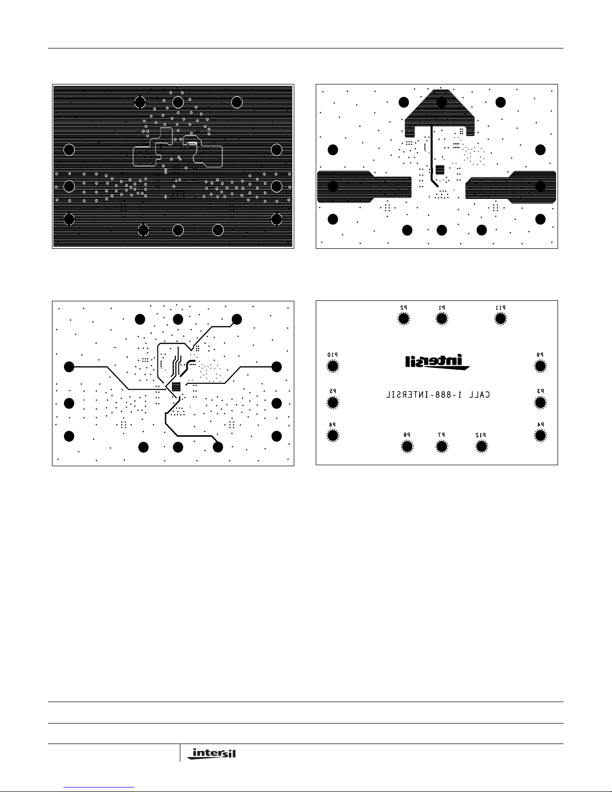
ISL6443AEVAL2Z Layout (Continued)
FIGURE 3. LAYER 2 FIGURE 4. LAYER 3
Application Note 1391
FIGURE 5. BOTTOM LAYER
Intersil Corporation reserves the right to make changes in circuit design, software and/or specifications at any time without notice. Accordingly, the reader is cautioned to
verify that the Application Note or Technical Brief is current before proceeding.
FIGURE 6. BOTTOM SILK
For information regarding Intersil Corporation and its products, see www.intersil.com
4
AN1391.0
March 10, 2008
 Loading...