

Intersil ISL5761EVAL1, ISL5861EVAL1, ISL5961EVAL1, ISL5761EVAL2, ISL5861EVAL2 User Manual
...Page 1
TM
ISL5x61EVAL1 and EVAL2 User’s Manual
Application Note September 2001
Description
The ISL5x61EVAL1 and EVAL2 evaluation boards provide a
quick and easy method for evaluati ng the
ISL5761/5861/5961 (10-, 12-, or 14-bit), 130/210MSPS high
speed DACs . EV AL1 is populated with an SOIC package and
EVAL2 is populated with a TSSOP package. The board is
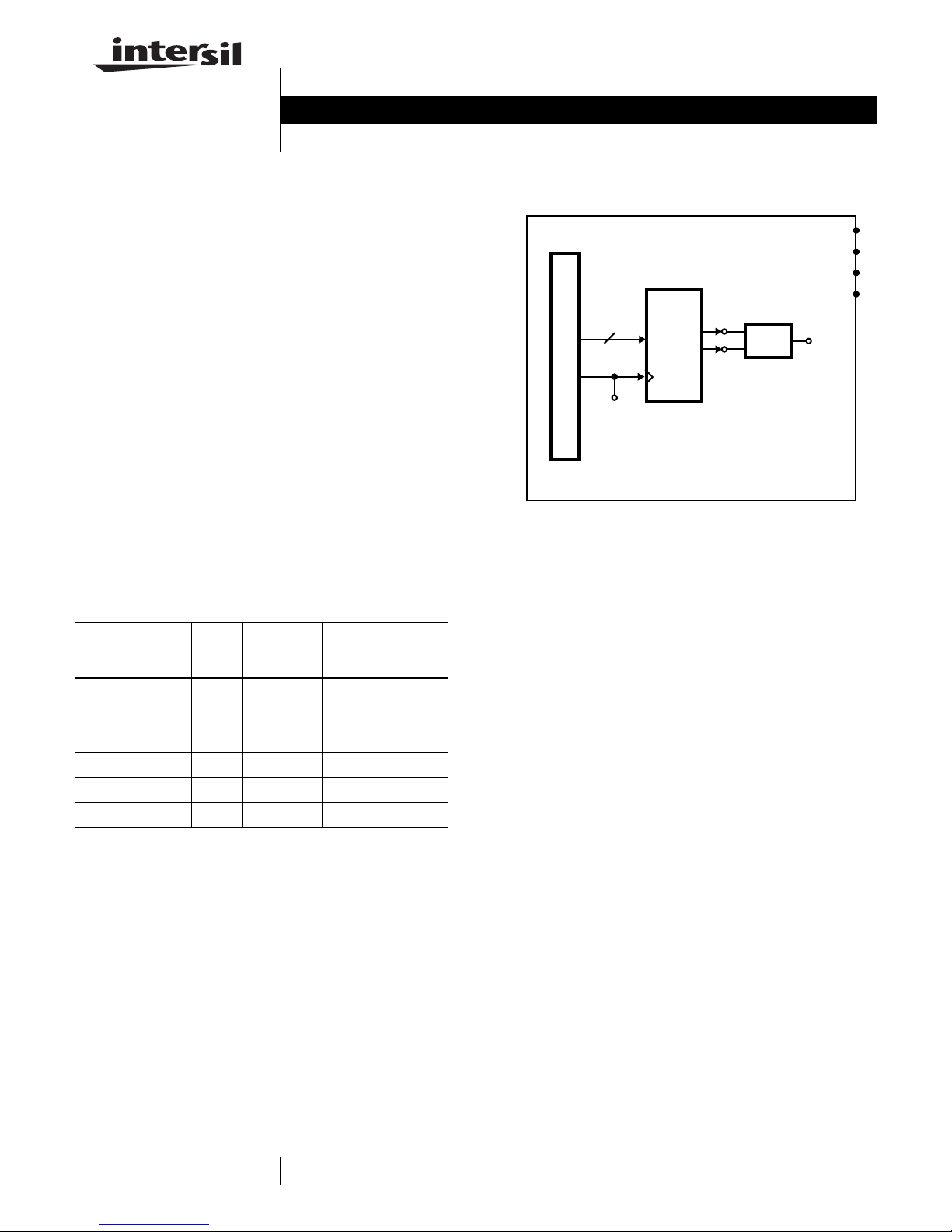
configured so that the converter outputs differential current
into a transformer circuit to form an output voltage. The
amount of current out of the DAC is determined by an
external resistor and either an internal or external reference
voltage. The CMOS digital inputs have optional external
termination resistors. The evaluation board includes a ribbon
cable digital interface that is compatible with Intersil DUC
(Digital Up Converter) evaluation boards like the ISL5217.
Features
• 210MSPS 10-, 12- or 14-Bit CMOS DAC
• Transformer-Coupled or Single-Ended SMA Outputs
• Interface compatible to the ISL5217 Digital Up Converter
allows complete Baseband-to-IF Demonstration
Ordering Information
TEMP.
PART
NUMBER
ISL5761EVAL1 25 SOIC 10 210MHz
ISL5861EVAL1 25 SOIC 12 210MHz
ISL5961EVAL1 25 SOIC 14 210MHz
ISL5761EVAL2 25 TSSOP 10 210MHz
ISL5861EVAL2 25 TSSOP 12 210MHz
ISL5961EVAL2 25 TSSOP 14 210MHz
RANGE
o
(
C) PACKAGE
NUMBER
OF BITS
CLOCK
SPEED
AN9966
Functional Block Diagram
DVDD PLANE
DGND PLANE
AVDD PLANE
AGND PLANE
T1
XFMR
IOUT
SMA
10-14 BITS
CLOCK
2x20 PIN HEADER
CLK
SMA
DAC
IOUTA
SMA
IOUTB
SMA
Getting Started
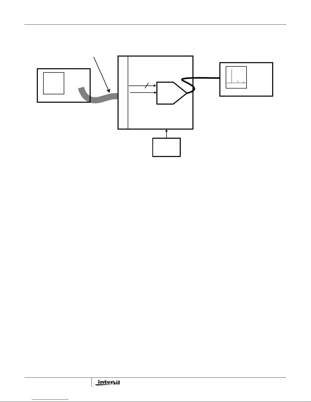
See Figure 1. A summary of the equipment, external
supplies and signal sources needed to operate the board is
given below:
1. +3.3V supply for ISL5x61 DA C.
2. Pattern generator (pattern source).
3. Square wave, DC-biased clock source (usually part of the
pattern generator).
4. Spectrum analyzer or oscilloscope for viewing the output
of the converter.
Attach the evaluation board to the power supply(s). Connect
the bits from the data generator to the evaluation board
using the 2x20 pin connector (J1). Connect the clock source
to the evaluation board, either through the 2x20 pin
connector (J1) or via the provided SMA (J2).
1
Using a coaxial cable with the proper SMA connector, attach
the output of the converter, I
(J11), to the measurement
OUT
equipment that will be evaluating the converter’s
performance. Make sure that the jumpers are in their proper
placement (default placement should be J5 and J10
populated, all others not populated).
Set the clock signal and data levels to swing from 0-3V. Turn
the power supply on. Turn the pattern and clock on and
measure the result at the analog output SMA (J11).
CAUTION: These devices are sensitive to electrostatic discharge; follow proper IC Handling Procedures.
1-888-INTERSIL or 321-724-7143
| Intersil and Design is a trademark of Intersil Americas Inc.
Copyright © Intersil Americas Inc. 2001, All Rights Reserved
Page 2
GORE QUIETZONE® CABLES
Application Note 9966
2x20 PIN HEADER
PATTERN GENERATOR
FIGURE 1. INTERSIL ISL5x61 EVALUATION SYSTEM SETUP BLOCK DIAGRAM
Board Options
Jumpers (Default State)
J3 - Selects DAC Sleep Mode (OPEN)
J4 - Selects External Reference (OPEN)
J5 - Selects Internal Reference (SHORT)
J6 - Selects IOUTA (OPEN)
J7 - Selects IOUTB (OPEN)
J10 - Grounds the Transformer Output (SHORT)
Output Transformer
T1 - T1-1T (case style Mini-Circuits KK81)
T2 - ADT1-1WT (case style Mini-Circuits CD542)
Clock
2x20 Pin Header (J1 - pin 19)
SMA - J2
RSET
Fixed Resistor - R34 (2kΩ = 20mA full scale output)
Potentiometer - R35
Power Supply
Split AVDD and DVDD
Single VDD (by connecting them together prior to the
inductors on the board)
ISL5x61 EVALUATION BOARD
14 BITS
ISL5x61
CLOCK
DAC
POWER
SUPPLY
+3.3V
Digital Inputs
The digital inputs are expecting 3V CMOS levels. The board
is shipped without termination resistors so that most systems
can drive the load. The board is configured so that the user
can populate 50Ω termination resistors if required (R1-15).
Consult the datasheet for the DAC for min/max amplitude
requirements for the clock and data.
Analog Outputs
The transformer configuration is such that it expects to see a
50Ω load at the end of an RF cable. If the user wishes to
evaluate the single-ended performance of the DAC, J6
and/or J7 will need to be populated, and R31/32 should be
populated with 50Ω resistors (or a resistor of choice that
does not cause the analog output to violate the output
voltage compliance range specified in the datasheet.)
Board Schematics/Layout/BOM
The schematics, board plots, and bill of materials can be
downloaded from the Intersil web site. Search on the DAC
part number.
Other
The labels on the board for IOUTB (J8) and IOUTA (J9) are
backwards. J8 should be IOUTA and J9 should be IOUTB.
ISL5x61 + ISL5217 Combo
The ISL5x61 evaluation board is designed to interface
directly to an ISL5217 evaluation board. The ISL5217 is a
104MSPS Digital Up Converter. The ISL5217 can be used to
50Ω
SMA
CABLE
SPECTRUM ANALYZER
2
Quietzone® is a registered trademark of W.L. Gore & Associates, Inc.
Page 3
Application Note 9966
generate 1-4 narrowband carriers or 1-2 wideband carriers.
Consult the ISL5217 documentation for detailed information
on using the ISL5217 evaluation board.
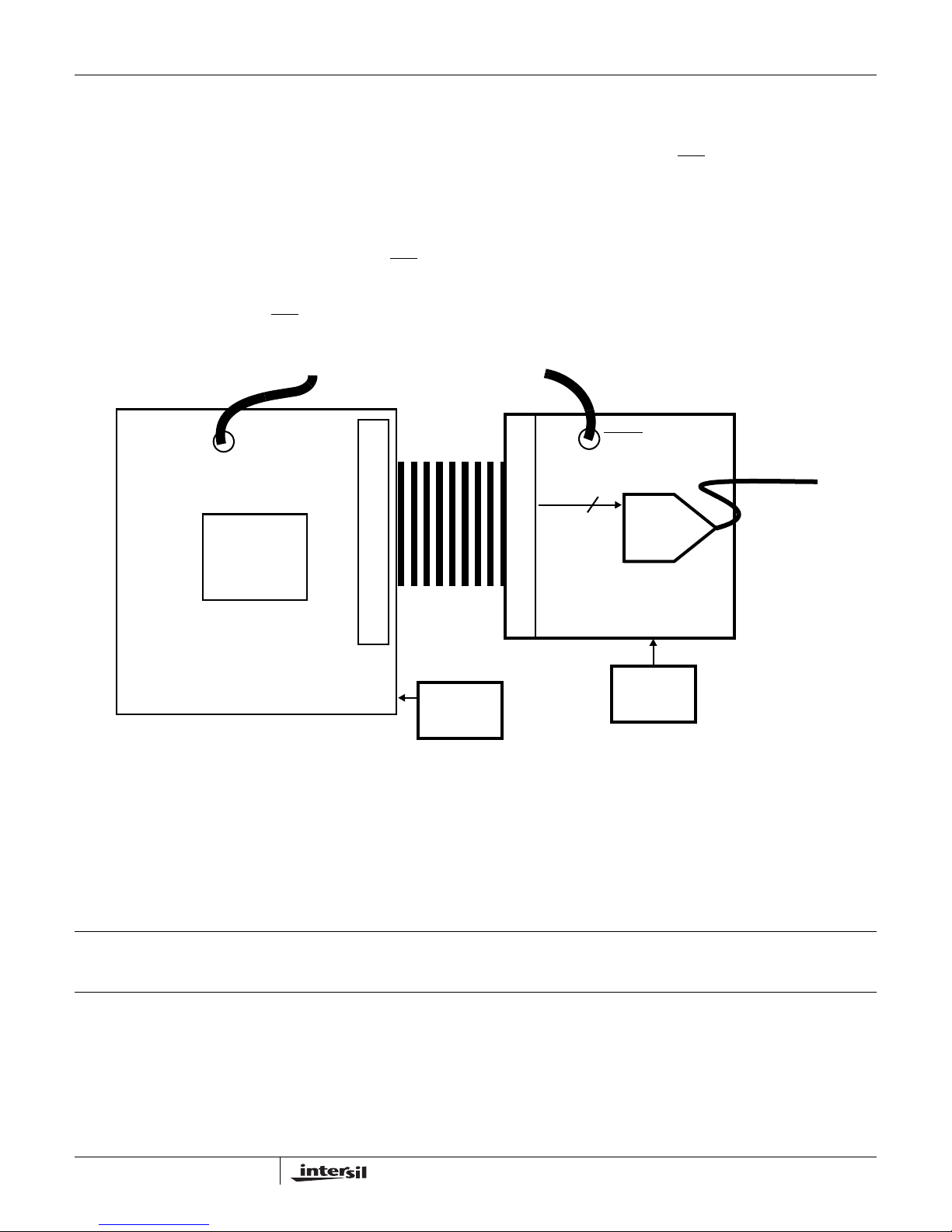
To connect the two boards together, J4 on the ISL5217eval
(DUC) is connected to J1 on the ISL5x61eval (DAC) via a
2x20 pin ribbon cable. The DAC board is configured as is
stocked, except R16 is not populated. See Figure 2 for a
block diagram of the two boards connected.
If a clock source is available that has both CLK and CLK
, the
clocking of the two boards is simplified. CLK should connect
to the DUC evaluation board at J11, with a T-connector that
has a 50Ω terminator attached. CLK
should go to the DAC
evaluation board at J2 and also use a T-connector with a
CLOCK (104M MAX)
ISL5217
4CH DIGITAL
UP CONVERTER
RIBBON CABLE
2x20 PIN HEADER
50Ω terminator. (Or, 50Ω terminators can be populated on
the evaluation boards. See the board schematics for more
information on doing this.)
If a generator with CLK and CLK
is not available, a single
clock source can be used. Connect a T-connector to J2 of
the DAC board and another to J11 of the DUC board.
Connect a DC-biased clock signal to the connector at J2,
then connect J2 and J11 together with a short cable.
Connect a 50Ω terminator to the other side of the
T-connector at J11 on the DUC board. Sometimes the length
of the clock cable running from the DAC board to the DUC
board has to be adjusted to achieve adequate setup and
hold times between DATA and CLK.
CLOCK (104M MAX)
14 BITS
ISL5x61
DAC
2x20 PIN HEADER
50Ω
SMA
CABLE
TO SPECTRUM
ANALYZER
ISL5x61 EVALUATION BOARD
+3.3V (<0.1A)
ISL5217 EVALUATION BOARD
FIGURE 2. INTERSIL ISL5x61 + ISL5217 SETUP BLOCK DIAGRAM
+5V (<2A)
POWER
SUPPLY
POWER
SUPPLY
All Intersil products are manufactured, assembled and tested utilizing ISO9000 quality systems .
Intersil Corporation’s quality certifications can be viewed at www.intersil.com/design/quality
Intersil products are sold by description only. Intersil Corporation reserves the right to make changes in circuit design and/or specifications at any time without notice.
Accordingly, the reader is cautioned to verify that data sheets are current before placing orders. Information furnished by Intersil is believed to be accurate and reliable.
However, no responsibility is assumed by Intersil or its subsidiaries for its use; nor for any infringements of patents or other rights of third parties which may result from its
use. No license is granted by implication or otherwise under any patent or patent rights of Intersil or its subsidiaries.
For information regarding Intersil Corporation and its products, see www.intersil.com
Sales Office Headquarters
NORTH AMERICA
Intersil Corporation
7585 Irvine Center Drive
Suite 100
Irvine, CA 92618
TEL: (949) 341-7000
FAX: (949) 341-7123
Intersil Corporation
2401 Palm Bay Rd.
Palm Bay, FL 32905
TEL: (321) 724-7000
FAX: (321) 724-7946
EUROPE
Intersil Europe Sarl
Ave. C - F Ramuz 43
CH-1009 Pully
Switzerland
TEL: +41 21 7293637
FAX: +41 21 7293684
ASIA
Intersil Corporation
Unit 1804 18/F Guangdong Water Building
83 Austin Road
TST, Kowloon Hong Kong
TEL: +852 2723 6339
FAX: +852 2730 1433
3
Page 4

Mouser Electronics
Authorized Distributor
Click to View Pricing, Inventory, Delivery & Lifecycle Information:
Intersil:
ISL5961EVAL1
 Loading...