

查询ISL5861EVAL1供应商
TM
ISL5861
Data Sheet September 2001
12-bit, +3.3V, 130/210+MSPS, CommLink
TM
High Speed D/A Converter
The ISL5861 is a 12-bit,
130/210+MSPS (Mega Samples
Per Second), CMOS, high speed,
low power, D/A (digital to analog) converter, designed
specifically for use in high performance communication
systems such as base transceiver stations utilizing 2.5G or
3G cellular protocols.
This device complements the CommLink ISL5x61 family of
high speed converters, which include 10, 12, and 14-bit
devices.
Ordering Information
TEMP.
PART
NUMBER
ISL5861IB -40 to 85 28 Ld SOIC M28.3 130MHz
ISL5861IA -40 to 85 28 Ld TSSOP M28.173 130MHz
ISL5861/2IB -40 to 85 28 Ld SOIC M28.3 210MHz
ISL5861/2IA -40 to 85 28 Ld TSSOP M28.173 210MHz
ISL5861EVAL1 25 SOIC Evaluation Platform 210MHz
RANGE
o
(
C) PACKAGE
PKG.
NO.
CLOCK
SPEED
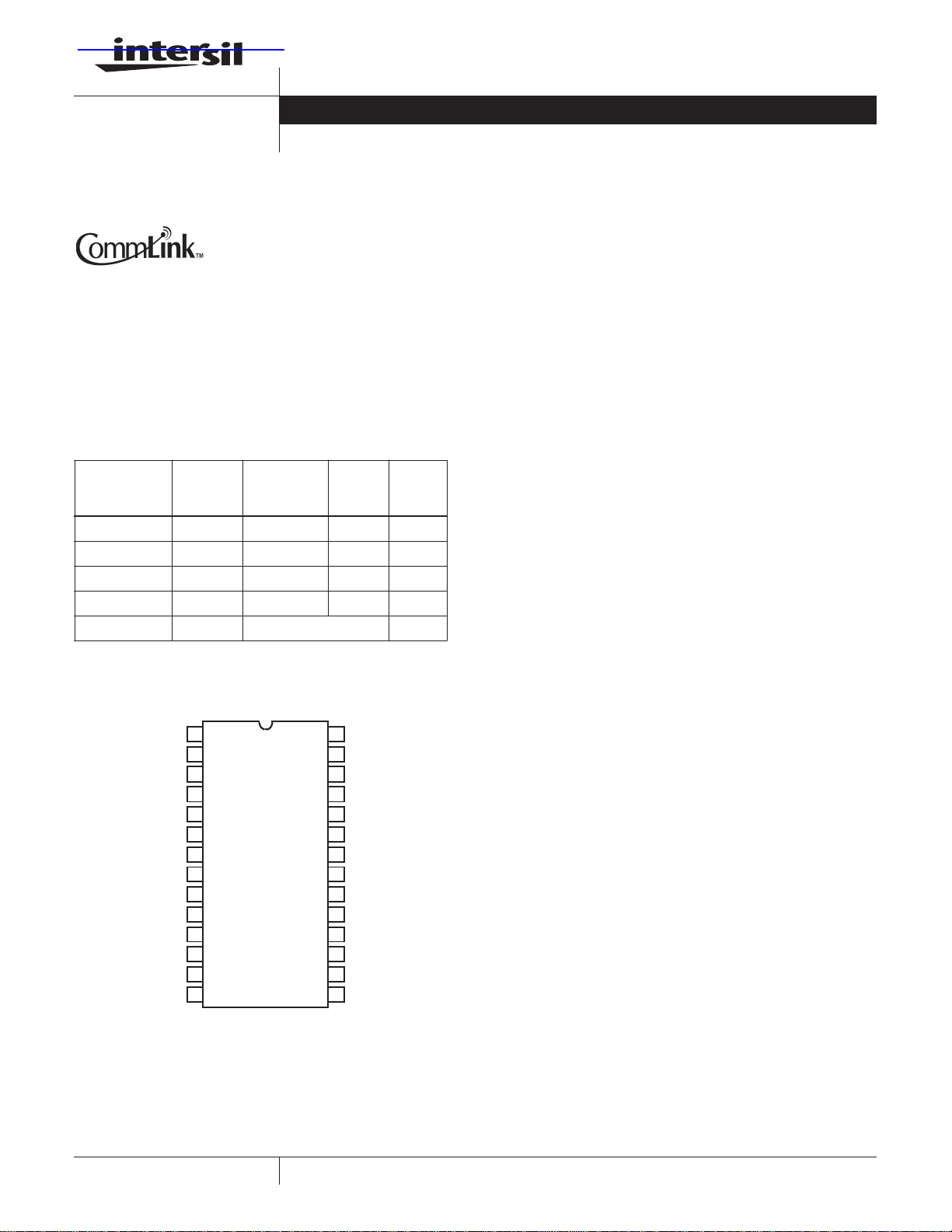
Pinout
ISL5861
TOP VIEW
File Number 6008.1
Features
• Speed Grades . . . . . . . . . . . . . . . . 130M and 210+MSPS
• Low Power . . . . . 103mW with 20mA Output at 130MSPS
• Adjustable Full Scale Output Current. . . . . 2mA to 20mA
• +3.3V Power Supply
• 3V LVCMOS Compatible Inputs
• Excellent Spurious Free Dynamic Range
(73dBc to Nyquist, f
= 130MSPS, f
S
OUT
= 10MHz)
• UMTS Adjacent Channel Power =70dB at 19.2MHz
• EDGE/GSM SFDR = 90dBc at 11MHz in 20MHz Window
• Pin compatible, 3.3V, Lower Power Replacement For The
AD9752 and HI5860
Applications
• Cellular Infrastructure - Single or Multi-Carrier: IS-136, IS95, GSM, EDGE, CDMA2000, WCDMA, TDS-CDMA
• BWA Infrastructure
• Medical/Test Instrumentation
• Wireless Communication Systems
• High Resolution Imaging Systems
• Arbitrary Waveform Generators
D11 (MSB)
D10
D9
D8
D7
D6
D5
D4
D3
D2
D1
D0 (LSB)
DCOM
DCOM
1
2
3
4
5
6
7
8
9
10
11
12
13
14
1
28
27
26
25
24
23
22
21
20
19
18
17
16
15
CLK
DV
DD
DCOM
NC
AV
DD
COMP
IOUTA
IOUTB
ACOM
NC
FSADJ
REFIO
REFLO
SLEEP
CAUTION: These devices are se nsitive t o electrostati c discharge; f ollow proper IC Handling Proce dures.
1-888-INTERSIL or 321-724-7143
| Intersil and Design is a trademark of Intersil Americas Inc.
Copyright © Intersil Americas Inc. 2001, All Rights Reserved
60096009CommLink™ is a trademark of Intersil Americas Inc.
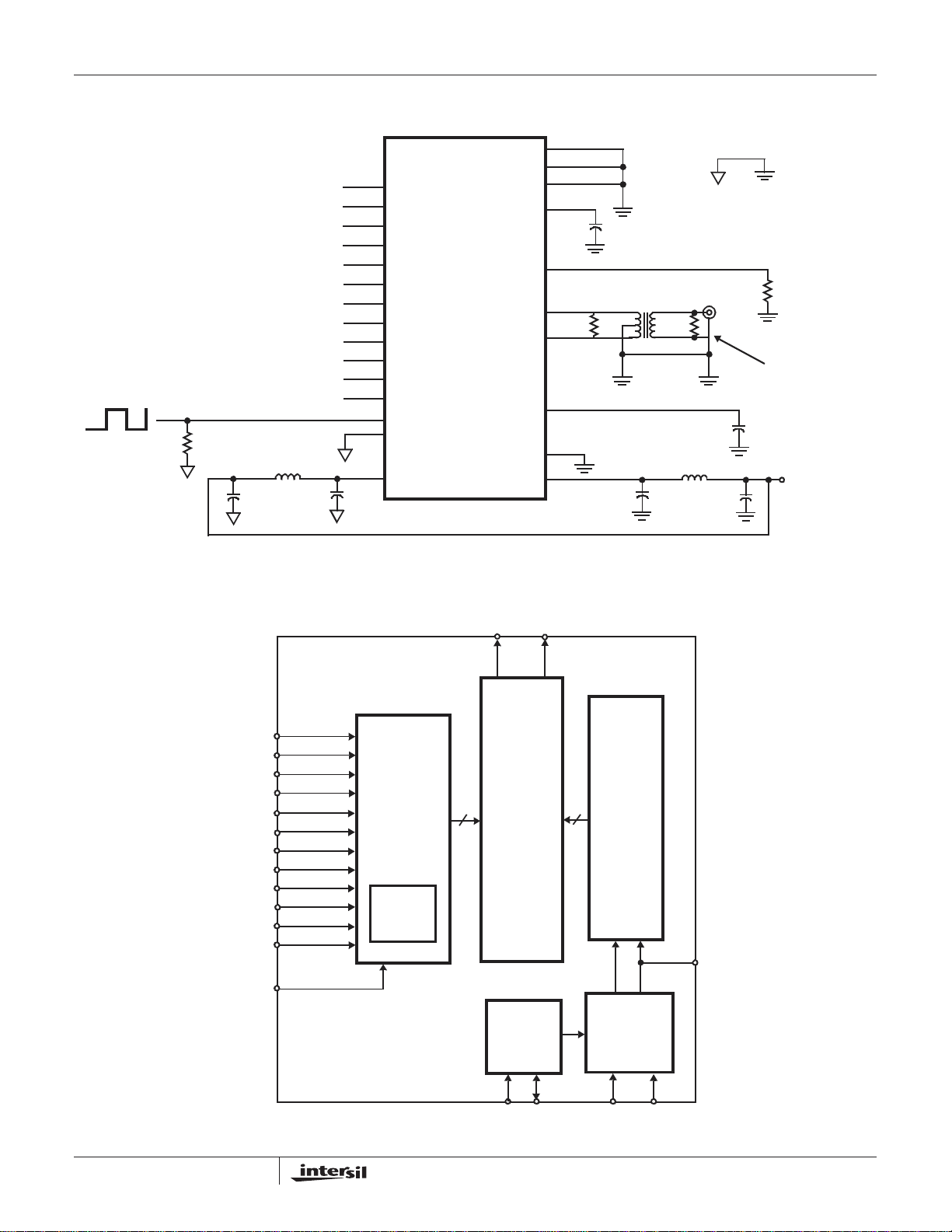
Typical Applications Circuit
50Ω
BEAD
+
10µF
10µH
0.1µF
D11
D10
D9
D8
D7
D6
D5
D4
D3
D2
D1
D0
ISL5861
ISL5861
D11 (MSB) (1)
D10 (2)
D9 (3)
D8 (4)
D7 (5)
D6 (6)
D5 (7)
D4 (8)
D3 (9)
D2 (10)
D1 (11)
D0 (LSB) (12)
CLK (28)
DCOM (26, 13, 14)
(27)
DV
DD
(25, 19) NC
(15) SLEEP
(16) REFLO
(17) REFIO
(18) FSADJ
(22) IOUTA
(21) IOUTB
(23) COMP
(20) ACOM
(24) AV
DD
ONE CONNECTION
ACOMDCOM
0.1µF
50Ω
1:1, Z1:Z2
0.1µF
(50Ω)
0.1µF
FERRITE
BEAD
10µH
10µF
R
SET
+
1.91kΩ
REPRESENTS
ANY 50Ω LOAD
+3.3V (VDD)
Functional Block Diagram
(LSB) D0
D1
D2
D3
D4
D5
D6
D7
D8
D9
D10
D11
CLK
INPUT
LATCH
UPPER
5-BIT
DECODER
IOUTA IOUTB
SWITCH
38
MATRIX
INT/EXT
VOLTAGE
REFERENCE
CASCODE
CURRENT
SOURCE
38
SEGMENTS
GENERATION
7 LSBs
31 MSB
BIAS
+
COMP
REFLO
REFIO
FSADJ SLEEP
2
ISL5861
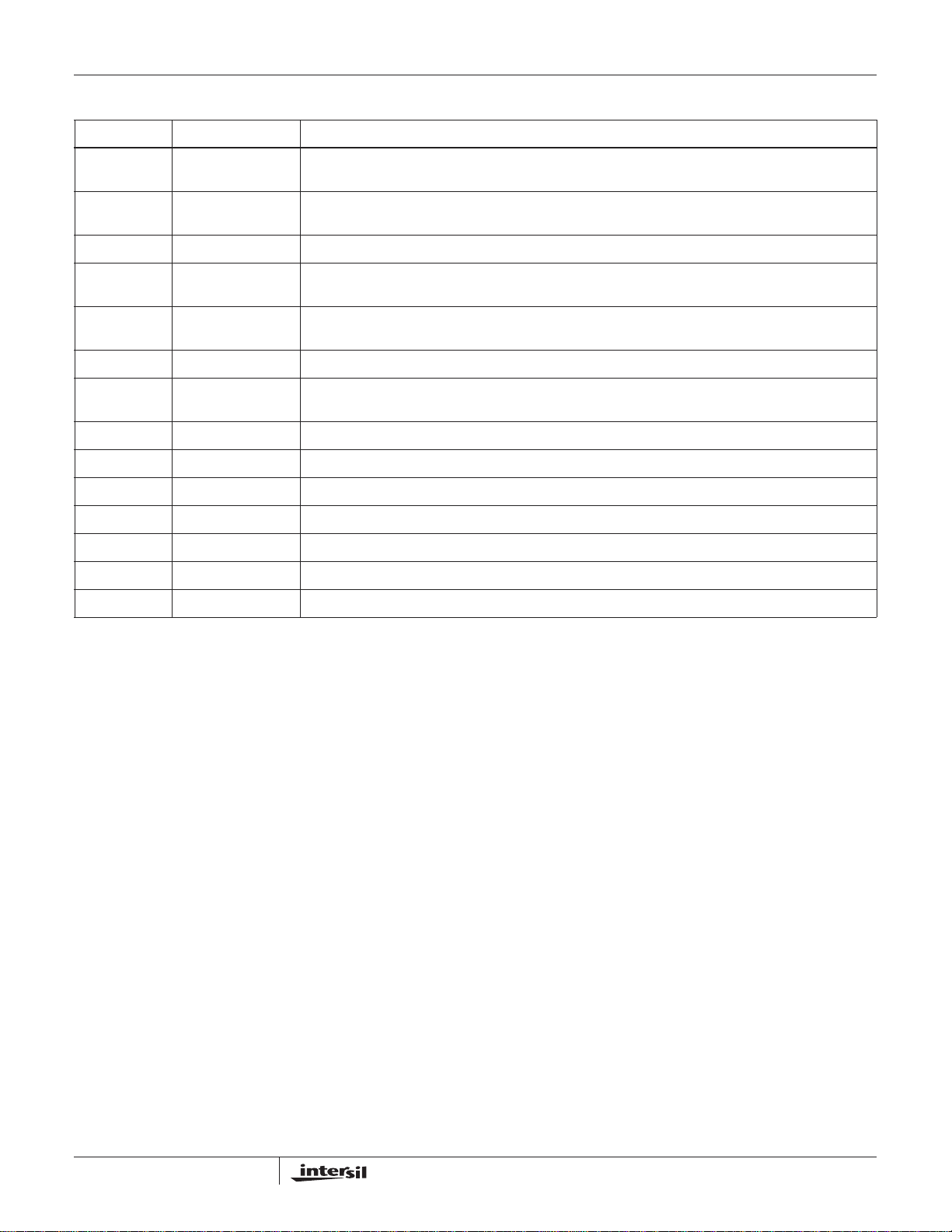
Pin Descriptions
PIN NO. PIN NAME DESCRIPTION
1-12 D11 (MSB) Through
D0 (LSB)
15 SLEEP Control Pin for Power-Down mode. Sleep Mode is active high; Connect to ground for Normal Mode. Sleep pin
16 REFLO Connect to analog ground to enable internal 1.2V reference or connect to AV
17 REFIO Reference voltage input if internal reference is disabled. Reference voltage output if internal reference is
18 FSADJ Full Scale Current Adjust. Use a resistor to ground to adjust full scale output current. Full Scale Output Current
19, 25 NC No Connect. These should be grounded, but can be left disconnected.
21 IOUTB The complementary current output of the device. Full scale output current is achieved when all input bits are
22 IOUTA Current output of the device. Full scale output current is achieved when all input bits are set to binary 1.
23 COMP Connect 0.1µF capacitor to ACOM.
24 AV
20 ACOM Connect to Analog Ground.
26, 13, 14 DCOM Connect to Digital Ground.
27 DV
28 CLK Clock Input.
DD
DD
Digital Data Bit 11, (Most Significant Bit) through Digital Data Bit 0, (Least Significant Bit).
has internal 20µA active pulldown current.
to disable internal reference.
DD
enabled. Use 0.1µF cap to ground when internal reference is enabled.
= 32 x V
FSADJ/RSET
set to binary 0.
Analog Supply (+3.0V to +3.6V).
Digital Supply (+3.0V to +3.6V).
.
3
ISL5861
Absolute Maximum Ratings Thermal Information
Digital Supply Voltage DVDD to DCOM . . . . . . . . . . . . . . . . . +3.6V
Analog Supply Voltage AV
to ACOM . . . . . . . . . . . . . . . . . +3.6V
DD
Grounds, ACOM TO DCOM . . . . . . . . . . . . . . . . . . . -0.3V to +0.3V
Digital Input Voltages (D9-D0, CLK, SLEEP). . . . . . . . DV
Reference Input Voltage Range. . . . . . . . . . . . . . . . . . AV
Analog Output Current (I
) . . . . . . . . . . . . . . . . . . . . . . . . . 24mA
OUT
DD
DD
+ 0.3V
+ 0.3V
Operating Conditions
Temperature Range . . . . . . . . . . . . . . . . . . . . . . . . . . -40oC to 85oC
CAUTION: Stresses above those listed in “Absolute Maximum Ratings” may cause permanent damage to the device. This is a stress only rating and operation of the
device at these or any other conditions above those indicated in the operational sections of this specification is not implied.
NOTE:
is measured with the component mounted on an evaluation PC board in free air.
1. θ
JA
Thermal Resistance (Typical, Note 1) θ
(oC/W)
JA
SOIC Package . . . . . . . . . . . . . . . . . . . . . . . . . . . . . 75
TSSOP Package . . . . . . . . . . . . . . . . . . . . . . . . . . . 110
Maximum Junction Temperature . . . . . . . . . . . . . . . . . . . . . . . 150
Maximum Storage Temperature Range . . . . . . . . . -65
o
C to 150oC
Maximum Lead Temperature (Soldering 10s) . . . . . . . . . . . . . 300
(SOIC - Lead Tips Only)
o
o
C
C
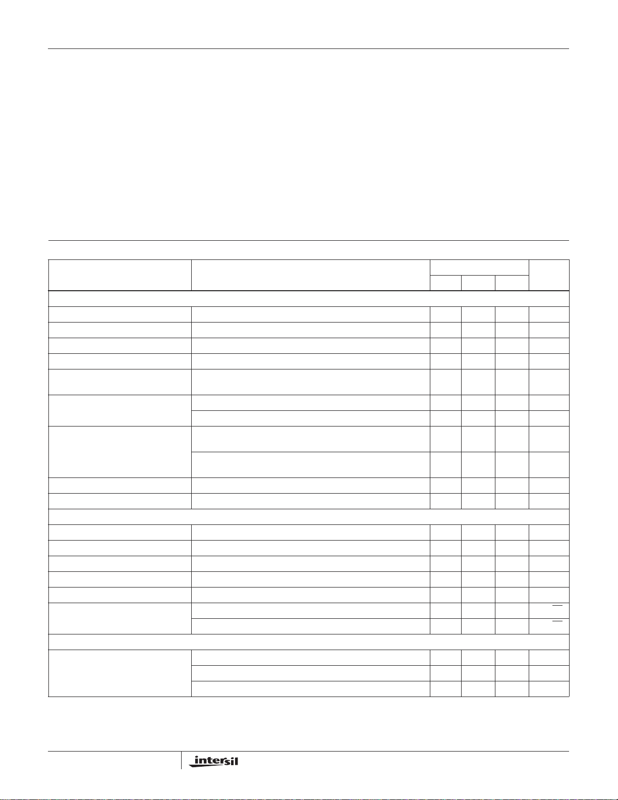
Electrical Specifications AV
PARAMETER TEST CONDITIONS
= DVDD = +3.3V, V
DD
= Internal 1.2V, IOUTFS = 20mA, TA = 25oC for All Typical Values
REF
T
= -40oC TO 85oC
A
UNITSMIN TYP MAX
SYSTEM PERFORMANCE
Resolution 12 - - Bits
Integral Linearity Error, INL “Best Fit” Straight Line (Note 7) -1.25 ±0.5 +1.25 LSB
Differential Linearity Error, DNL (Note 7) -1 ±0.5 +1 LSB
Offset Error, I
Offset Drift Coefficient (Note 7) - 0.1 - ppm
IOUTA (Note 7) -0.006 +0.006 % FSR
OS
FSR/
o
C
Full Scale Gain Error, FSE With External Reference (Notes 2, 7) -3 ±0.5 +3 % FSR
With Internal Reference (Notes 2, 7) -3 ±0.5 +3 % FSR
Full Scale Gain Drift With External Reference (Note 7) - ±50 - ppm
With Internal Reference (Note 7) - ±100 - ppm
Full Scale Output Current, I
FS
2-20mA
FSR/
FSR/
o
C
o
C
Output Voltage Compliance Range (Note 3) -1.0 - 1.25 V
DYNAMIC CHARACTERISTICS
Maximum Clock Rate, f
Maximum Clock Rate, f
CLK
CLK
ISL5861/2IA, ISL5861/2IB 210 250 - MHz
ISL5861IA, ISL5861IB 130 150 - MHz
Output Rise Time Full Scale Step - 1.5 - ns
Output Fall Time Full Scale Step - 1.5 - ns
Output Capacitance -10 - pF
Output Noise IOUTFS = 20mA - 50 - pA/√Hz
IOUTFS = 2mA - 30 - pA/√Hz
AC CHARACTERISTICS (Using Figure 13 with R
Spurious Free Dynamic Range,
SFDR Within a Window
= 210MSPS, f
f
CLK
= 210MSPS, f
f
CLK
= 130MSPS, f
f
CLK
= 50Ω and R
DIFF
= 50Ω, Full Scale Output = -2.5dBm)
LOAD
= 80.8MHz, 30MHz Span (Notes 4, 7) - 73 - dBc
OUT
= 40.4MHz, 30MHz Span (Notes 4, 7) - 80 - dBc
OUT
= 20.2MHz, 20MHz Span (Notes 4, 7) - 85 - dBc
OUT
4

ISL5861
Electrical Specifications AV
PARAMETER TEST CONDITIONS
Spurious Free Dynamic Range,
SFDR to Nyquist (f
Spurious Free Dynamic Range,
SFDR in a Window with Eight Tones
CLK
/2)
= DVDD = +3.3V, V
DD
f
= 210MSPS, f
CLK
= 210MSPS, f
f
CLK
= 200MSPS, f
f
CLK
= 200MSPS, f
f
CLK
= 130MSPS, f
f
CLK
= 130MSPS, f
f
CLK
= 130MSPS, f
f
CLK
= 130MSPS, f
f
CLK
= 130MSPS, f
f
CLK
= 130MSPS, f
f
CLK
= 100MSPS, f
f
CLK
= 80MSPS, f
f
CLK
= 80MSPS, f
f
CLK
= 80MSPS, f
f
CLK
= 80MSPS, f
f
CLK
= 50MSPS, f
f
CLK
= 50MSPS, f
f
CLK
= 50MSPS, f
f
CLK
= 210MSPS, f
f
CLK
50MHz Span (Notes 4, 7, 9)
f
= 130MSPS, f
CLK
REF
OUT
OUT
OUT
OUT
OUT
OUT
OUT
OUT
OUT
OUT
OUT
OUT
OUT
OUT
OUT
OUT
OUT
OUT
OUT
OUT
= Internal 1.2V, IOUTFS = 20mA, TA = 25oC for All Typical Values (Continued)
T
= -40oC TO 85oC
A
UNITSMIN TYP MAX
= 80.8MHz (N otes 4, 7) - 51 - dBc
= 40.4MHz (N otes 4, 7, 9) - 60 - dBc
= 20.2MHz, T = 25oC (Notes 4, 7) 60 62 - dBc
= 20.2MHz, T = -40oC to 85oC (Notes 4, 7) 58 - - dBc
= 50.5MHz (N otes 4, 7) - 57 - dBc
= 40.4MHz (N otes 4, 7) - 62 - dBc
= 20.2MHz (N otes 4, 7) - 69 - dBc
= 10.1MHz (N otes 4, 7) - 73 - dBc
= 5.05MHz, T = 25oC (Notes 4, 7) 70 77 - dBc
= 5.05MHz, T = -40oC to 85oC (Notes 4, 7) 68 - - dBc
= 40.4MHz (N otes 4, 7) - 60 - dBc
= 30.3MHz (Notes 4, 7) - 63 - dBc
= 20.2MHz (Notes 4, 7) - 69 - dBc
= 10.1MHz (Notes 4, 7, 9) - 70 - dBc
= 5.05MHz (Notes 4, 7) - 76 - dBc
= 20.2MHz (Notes 4, 7) - 68 - dBc
= 10.1MHz (Notes 4, 7) - 73 - dBc
= 5.05MHz (Notes 4, 7) - 77 - dBc
= 28.3MHz to 45.2MHz, 2.1MHz Spacing,
=17.5MHz to 27.9MHz, 1.3MHz Spacing,
-65 - dBc
-68 - dBc
35MHz Span (Notes 4, 7)
f
Spurious Free Dynamic Range,
SFDR in a Window with EDGE or GSM
Adjacent Channel Power Ratio,
= 80MSPS, f
CLK
15MHz Span (Notes 4, 7)
f
= 50MSPS, f
CLK
10MHz Span (Notes 4, 7)
f
= 78MSPS, f
CLK
(Notes 4, 7, 9)
f
= 76.8MSPS, f
CLK
= 10.8MHz to 17.2MHz, 811kHz Spacing,
OUT
= 6.7MHz to 10.8MHz, 490kHz Spacing,
OUT
= 11MHz, in a 20MHz Window, RBW=30kHz
OUT
= 19.2MHz, RBW=30kHz (Notes 4, 7, 9) - 70 - dB
OUT
-75 - dBc
-77 - dBc
-90 - dBc
ACPR with UMTS
VOLTAGE REFERENCE
Internal Reference Voltage, V
FSADJ
Pin 18 Voltage with Internal Reference 1.2 1.23 1.3 V
Internal Reference Voltage Drift - ±40 - ppm/
Internal Reference Output Current
Reference is not intended to be externally loaded - 0 - µA
Sink/Source Capability
Reference Input Impedance -1 -MΩ
Reference Input Multiplying Bandwidth (Note 7) - 1.0 - MHz
DIGITAL INPUTS D11-D0, CLK
Input Logic High Voltage with
3.3V Supply, V
IH
Input Logic Low Voltage with
3.3V Supply, V
Sleep Input Current, I
IL
IH
(Note 3) 2.3 3.3 - V
(Note 3) - 0 1.0 V
-25 - +25 µA
o
C
5

ISL5861
Electrical Specifications AV
PARAMETER TEST CONDITIONS
Input Logic Current, I
Clock Input Current, I
Digital Input Capacitance, C
IH, IL
IH, IL
IN
= DVDD = +3.3V, V
DD
= Internal 1.2V, IOUTFS = 20mA, TA = 25oC for All Typical Values (Continued)
REF
T
= -40oC TO 85oC
A
-20 - +20 µA
-10 - +10 µA
-5 - pF
UNITSMIN TYP MAX
TIMING CHARACTERISTICS
Data Setup Time, t
Data Hold Time, t
SU
HLD
Propagation Delay Time, t
CLK Pulse Width, t
PW1
, t
PD
PW2
See Figure 15 - 1.5 - ns
See Figure 15 - 1.5 - ns
See Figure 15 - 1 - Clock
Period
See Figure 15 (Note 3) 2 - - ns
POWER SUPPLY CHARACTERISTICS
Power Supply (Note 8) 2.7 3.3 3.6 V
AV
DD
Power Supply (Note 8) 2.7 3.3 3.6 V
DV
DD
Analog Supply Current (I
) 3.3V, IOUTFS = 20mA - 27.5 28.5 mA
AVDD
3.3V, IOUTFS = 2mA - 10 - mA
Digital Supply Current (I
) 3.3V (Note 5) - 3.7 5 mA
DVDD
3.3V (Note 6) - 6.5 8 mA
Supply Current (I
) Sleep Mode 3.3V, IOUTFS = Don’t Care - 1.5 - mA
AVDD
Power Dissipation 3.3V, IOUTFS = 20mA (Note 5) - 103 111 mW
3.3V, IOUTFS = 20mA (Note 6) - 110 120 mW
3.3V, IOUTFS = 2mA (Note 5) - 45 - mW
Power Supply Rejection Single Supply (Note 7) -0.125 - +0.125 %FSR/V
NOTES:
2. Gain Error measured as the error in the ratio between the full scale output current and the current through R
ratio should be 32.
(typically 625µA). Ideally the
SET
3. Parameter guaranteed by design or characterization and not production tested.
4. Spectral measurements made with differential transformer coupled output and no external filtering. For multitone testing, the same pattern was
used at different clock rates, producing different output frequencies but at the same ratio to the clock rate.
5. Measured with the clock at 130MSPS and the output frequency at 5MHz.
6. Measured with the clock at 200MSPS and the output frequency at 20MHz.
7. See “Definition of Specifications”.
8. Recommended operation is from 3.0V to 3.6V. Operation below 3.0V is possible with some degradation in spectral performance. Reduction in
analog output current may be necessary to maintain spectral performance.
9. See Typical Performance Plots.
6

ISL5861
Typical Performance (+3.3V Supply, Using Figure 13 with R
SPECTRAL MASK FOR
GSM900/DCS1800/PCS1900
P>43dBm NORMAL BTS
WITH 30kHz RBW
FIGURE 1. EDGE AT 11MHz, 78MSPS CLOCK
(91+dBc @ ∆f = +6MHz)
SPECTRAL MASK FOR
GSM900/DCS1800/PCS1900
P>43dBm NORMAL BTS
WITH 30kHz RBW
= 100Ω and R
DIFF
= 50Ω)
LOAD
FIGURE 2. EDGE AT 11MHz, 78MSPS CLOCK
(75dBc -NYQUIST, 6dB PAD)
FIGURE 3. GSM AT 11MHz, 78MSPS CLOCK
(90+dBc @ ∆f = +6MHz, 3dB PAD)
FIGURE 5. FOUR EDGE CARRIERS AT 12.4-15.6MHz, 800kHz
SPACING, 78MSPS (71dBc - 20MHz WINDOW)
7
FIGURE 4. GSM AT 11MHz, 78MSPS CLOCK
(75dBc - NYQUIST, 9dB PAD)
FIGURE 6. FOUR GSM CARRIERS AT 12.4-15.6MHz, 78MSPS
(73dBc - 20MHz WINDOW, 6dB PAD)

ISL5861
Typical Performance (+3.3V Supply, Using Figure 13 with R
SPECTRAL MASK
UMTS TDD
P>43dBm BTS
FIGURE 7. UMTS AT 19.2MHz, 76.8MSPS (70dB 1stACPR,
70dB 2ndACPR)
= 100Ω and R
DIFF
= 50Ω) (Continued)
LOAD
FIGURE 8. ONE TONE AT 10.1MHz, 80MSPS CLOCK (71dBc -
NYQUIST, 6dB PAD)
FIGURE 9. ONE TONE AT 40.4MHz, 210MSPS CLOCK
(61dBc - NYQUIST, 6dB PAD)
FIGURE 11. TWO TONES (CkHzF=6) AT 8.5MHz, 50MSPS
CLOCK, 500kHz SPACING (82dBc - 10MHz
WINDOW, 6dB PAD)
8
FIGURE 10. EIGHT TONES (CREST FACTOR=8.9) AT 37MHz,
210MSPS CLOCK, 2.1MHz SPACING
(65dBc - NYQUIST)
FIGURE 12. FOUR TONES (CF=8.1) AT 14MHz, 80MSPS
CLOCK, 800kHz SPACING (70dBc - NYQUIST,
6dB PAD)

ISL5861
Definition of Specifications
Adjacent Channel Power Ratio, ACPR, is the ratio of the
average power in the adjacent frequency channel (or offset)
to the average power in the transmitted frequency channel.
Differential Linearity Error, DNL, is the measure of the
step size output deviation from code to code. Ideally the step
size should be 1 LSB. A DNL specification of 1 LSB or less
guarantees monotonicity.
EDGE, Enhanced Data for Global Evolution, a TDMA
standard for cellular applications which uses 200kHz BW, 8PSK modulated carriers.
Full Scale Gain Drift, is measured by setting the data inputs
to be all logic high (all 1s) and measuring the output voltage
through a known resistance as the temperature is varied
MIN
to T
from T
from the value measured at room temperature to the value
measured at either T
(full scale range) per
Full Scale Gain Error , is the error from an ideal ratio of 32
between the output current and the full scale adjust current
(through R
SET
GSM, Global System for Mobile Communication, a TDMA
standard for cellular applications which uses 200kHz BW,
GMSK modulated carriers.
Integral Linearity Error, INL, is the measure of the worst
case point that deviates from a best fit straight line of data
values along the transfer curve.
Internal Reference Voltage Drift, is defined as the
maximum deviation from the value measured at room
temperature to the value measured at either T
The units are ppm per
Offset Drift, is measured by setting the data inputs to all
logic low (all 0s) and measuring the output voltage at IOUTA
through a known resistance as the temperature is varied
MIN
to T
from T
from the value measured at room temperature to the value
measured at either T
(full scale range) per degree
Offset Error, is measured by setting the data inputs to all
logic low (all 0s) and measuring the output voltage of IOUTA
through a known resistance. Offset error is defined as the
maximum deviation of the IOUTA output current from a value
of 0mA.
Output Voltage Compliance Range, is the voltage limit
imposed on the output. The output impedance should be
chosen such that the voltage developed does not violate the
compliance range.
Power Supply Rejection, is measured using a single power
supply. The nominal supply voltage is varied
change in the DAC full scale output is noted.
. It is defined as the maximum deviation
MAX
MIN
o
or T
C.
. The units are ppm of FSR
MAX
).
o
C.
. It is defined as the maximum deviation
MAX
MIN
or T
. The units are ppm of FSR
MAX
o
C.
MIN
±10% and the
or T
MAX
Reference Input Multiplying Bandwidth, is defined as the
3dB bandwidth of the voltage reference input. It is measured
by using a sinusoidal waveform as the external reference
with the digital inputs set to all 1s. The frequency is
increased until the amplitude of the output waveform is
0.707 (-3dB) of its original value.
Spurious Free Dynamic Range, SFDR, is the amplitude
difference from the fundamental signal to the largest
harmonically or non-harmonically related spur within the
specified frequency window.
Total Harmonic Distortion, THD, is the ratio of the RMS
value of the fundamental output signal to the RMS sum of
the first five harmonic components.
UMTS, Universal Mobile Telecommunications System, a
W-CDMA standard for cellular applications which uses
3.84MHz modulated carriers.
Detailed Description
The ISL5861 is a 12-bit, current out, CMOS, digital to analog
converter. The maximum update rate is at least 210+MSPS
and can be powered by a single power supply in the
recommended range of +3.0V to +3.6V. Operation with clock
rates higher than 210MSPS is possible; please contact the
factory for more information. It consumes less than 120mW
of power when using a +3.3V supply, the maximum 20mA of
output current, and the data switching at 210MSPS. The
architecture is based on a segmented current source
arrangement that reduces glitch by reducing the amount of
current switching at any one time. In previous architectures
that contained all binary weighted current sources or a
binary weighted resistor ladder, the converter might have a
.
substantially larger amount of current turning on and off at
certain, worst-case transition points such as midscale and
quarter scale transitions. By greatly reducing the amount of
current switching at these major transitions, the overall glitch
of the converter is dramatically reduced, improving settling
time, transient problems, and accuracy.
Digital Inputs and Termination
The ISL5861 digital inputs are guaranteed to 3V LVCMOS
levels. The internal register is updated on the rising edge of
the clock. To minimize reflections, proper termination should
be implemented. If the lines driving the clock and the digital
inputs are long 50Ω lines, then 50Ω termination resistors
should be placed as close to the converter inputs as possible
connected to the digital ground plane (if separate grounds
are used). These termination resistors are not likely needed
as long as the digital waveform source is within a few inches
of the DAC. For pattern drivers with very high speed edge
rates, it is recommended that the user consider series
termination (50-200Ω) prior to the DAC’s inputs in order to
reduce the amount of noise.
9

ISL5861
Power Supply
Separate digital and analog power supplies are
recommended. The allowable supply range is +2.7V to
+3.6V. The recommended supply range is +3.0 to 3.6V
(nominally +3.3V) to maintain optimum SFDR. However,
operation down to +2.7V is possible with some degradation
in SFDR. Reducing the analog output current can help the
SFDR at +2.7V. The SFDR values stated in the table of
specifications were obtained with a +3.3V supply.
Ground Planes
Separate digital and analog ground planes should be used.
All of the digital functions of the device and their
corresponding components should be located over the
digital ground plane and terminated to the digital ground
plane. The same is true for the analog components and the
analog ground plane.
Noise Reduction
To minimize power supply noise, 0.1µF capacitors should be
placed as close as possible to the converter’s power supply
pins, AV
and DVDD. Also, the layout should be designed
DD
using separate digital and analog ground planes and these
capacitors should be terminated to the digital ground for
and to the analog ground for AVDD. Additional filtering
DV
DD
of the power supplies on the board is recommended.
Voltage Reference
The internal voltage reference of the device has a nominal
value of +1.23V with a ±40ppm/
full temperature range of the converter. It is recommended
that a 0.1µF capacitor be placed as close as possible to the
REFIO pin, connected to the analog ground. The REFLO pin
(16) selects the reference. The internal reference can be
selected if pin 16 is tied low (ground). If an external
reference is desired, then pin 16 should be tied high (the
analog supply voltage) and the external reference driven into
REFIO, pin 17. The full scale output current of the converter
is a function of the voltage reference used and the value of
. I
R
SET
should be within the 2mA to 20mA range,
OUT
though operation below 2mA is possible, with performance
degradation.
If the internal reference is used, V
approximately 1.2V (pin 18). If an external reference is used,
V
I
I
will equal the external reference. The calculation for
FSADJ
(Full Scale) is:
OUT
(Full Scale) = (V
OUT
FSADJ/RSET)
If the full scale output current is set to 20mA by using the
internal voltage reference (1.2V) and a 1.91kΩ R
resistor, then the input coding to output current will resemble
the following:
o
C drift coefficient over the
will equal
FSADJ
X 32.
SET
TABLE 1. INPUT CODING vs OUTPUT CURRENT WITH
INTERNAL REFERENCE AND RSET=1.91KΩ
INPUT CODE (D11-D0) IOUTA (mA) IOUTB (mA)
11 11111 11111 20 0
10 00000 00000 10 10
00 00000 00000 0 20
Analog Output
IOUTA and IOUTB are complementary current outputs. The
sum of the two currents is always equal to the full scale
output current minus one LSB. If single ended use is
desired, a load resistor can be used to convert the output
current to a voltage. It is recommended that the unused
output be either grounded or equally terminated. The voltage
developed at the output must not violate the output voltage
compliance range of -1.0V to 1.25V. R
(the impedance
OUT
loading each current output) should be chosen so that the
desired output voltage is produced in conjunction with the
output full scale current. If a known line impedance is to be
driven, then the output load resistor should be chosen to
match this impedance. The output voltage equation is:
V
OUT
= I
OUT
X R
OUT
.
The most effective method for reducing the power
consumption is to reduce the analog output current, which
dominates the supply current. The maximum recommended
output current is 20mA.
Differential Output
IOUTA and IOUTB can be used in a differential-to-singleended arrangement to achieve better harmonic rejection.
With R
will provide a 500mV (-2.5dBm) signal at the output of the
transformer if the full scale output current of the DAC is set
to 20mA (used for the electrical specifications table). Values
of R
performance curves. The center tap in Figure 13 must be
grounded.
In the circuit in Figure 14, the user is left with the option to
ground or float the center tap. The DC voltage that will exist
at either IOUTA or IOUTB if the center tap is floating is
IOUT
transformer. If the center tap is grounded, the DC voltage is
0V. Recommended values for the circuit in Figure 14 are
R
A=RB
performance of Figure 13 and Figure 14 is basically the
same, however leaving the center tap of Figure 14 floating
allows the circuit to find a more balanced virtual ground,
theoretically improving the even order harmonic rejection,
but likely reducing the signal swing available due to the
output voltage compliance range limitations.
= 50Ω and R
DIFF
= 100Ω and R
DIFF
x (RA//RB) V because R
DC
=50Ω, R
LOAD
=100Ω, assuming R
DIFF
=50Ω, the circuit in Figure 13
LOAD
=50Ω were used for the typical
is DC shorted by the
DIFF
=50Ω. The
LOAD
10

ISL5861
R
= 0.5 x (R
EQ
AT EACH OUTPUT
PIN 21
PIN 22
ISL5861
LOAD
// R
)
DIFF
V
= (2 x IOUTA x REQ)V
OUT
IOUTB
R
DIFF
IOUTA
REPRESENTS THE
R
LOAD
LOAD SEEN BY THE TRANSFORMER
1:1
FIGURE 13. OUTPUT LOADING FOR DATASHEET
MEASUREMENTS
REQ = 0.5 x (R
AT EACH OUTPUT
PIN 21
PIN 22
ISL5861
LOAD
// R
IOUTB
IOUTA
// RA), WHERE RA=R
DIFF
R
A
R
DIFF
R
B
REPRESENTS THE
R
LOAD
LOAD SEEN BY THE TRANSFORMER
B
V
= (2 x IOUTA x REQ)V
OUT
FIGURE 14. ALTERNATIVE OUTPUT LOADING
R
R
LOAD
LOAD
Propagation Delay
The converter requires two clock rising edges for data to be
represented at the output. Each rising edge of the clock
captures the present data word and outputs the previous
data. The propagation delay is therefore 1/CLK, plus <2ns of
processing. See Figure 15.
Test Service
Intersil offers customer-specific testing of CommLink
converters with a service called Testdrive. To submit a
request, fill out the Testdrive form. The form can be found by
doing an ‘entire site search’ at www.intersil.com on the
words ‘DAC Testdrive’. Or, send a request to the technical
support center.
Timing Diagram
CLK
D11-D0
I
OUT
t
PW1
t
SU
t
HLD
W
0
t
PD
t
PW2
t
SU
OUTPUT=W
50%
t
SU
t
HLD
W
1
t
PD
OUTPUT=W
-1
W
2
0
t
HLD
OUTPUT=W
W
3
1
FIGURE 15. PROPAGATION DELAY, SETUP TIME, HOLD TIME AND MINIMUM PULSE WIDTH DIAGRAM
11

Small Outline Plastic Packages (SOIC)
ISL5861
N
INDEX
AREA
123
SEATING PLANE
-AD
e
B
0.25(0.010) C AM BS
M
E
-B-
A
-C-
0.25(0.010) BM M
H
α
µ
A1
0.10(0.004)
L
h x 45
o
NOTES:
1. Symbols are defined in the “MO Series Symbol List” in Section 2.2
of Publication Number 95.
2. Dimensioning and tolerancing per ANSI Y14.5M-1982.
3. Dimension “D” does not include mold flash, protrusions or gate
burrs. Mold flash, protrusion and gate burrs shall not exceed
0.15mm (0.006 inch) per side.
4. Dimension “E” does not include interlead flash or protrusions. Interlead flash and protrusions shall not exceed 0.25mm (0.010
inch) per side.
5. The chamfer on the body is optional. If it is not present, a visual
index feature must be located within the crosshatched area.
6. “L” is the length of terminal for soldering to a substrate.
7. “N” is the number of terminal positions.
8. Terminal numbers are shown for reference only.
9. The lead width “B”, as measured 0.36mm (0.014 inch) or greater
above the seating plane, shall not exceed a maximum value of
0.61mm (0.024 inch)
10. Controlling dimension: MILLIMETER. Converted inch dimensions are not necessarily exact.
M28.3 (JEDEC MS-013-AE ISSUE C)
28 LEAD WIDE BODY SMALL OUTLINE PLASTIC PACKAGE
INCHES MILLIMETERS
SYMBOL
A 0.0926 0.1043 2.35 2.65 -
A1 0.0040 0.0118 0.10 0.30 -
B 0.013 0.0200 0.33 0.51 9
C 0.0091 0.0125 0.23 0.32 -
D 0.6969 0.7125 17.70 18.10 3
E 0.2914 0.2992 7.40 7.60 4
e 0.05 BSC 1.27 BSC -
H 0.394 0.419 10.00 10.65 -
C
h 0.01 0.029 0.25 0.75 5
L 0.016 0.050 0.40 1.27 6
N28 287
o
α
0
o
8
o
0
o
8
Rev. 0 12/93
NOTESMINMAXMINMAX
-
12

ISL5861
Thin Shrink Small Outline Plastic Packages (TSSOP)
N
INDEX
AREA
123
-A-
0.05(0.002)
D
SEATING PLANE
e
b
0.10(0.004) C AM BS
M
E1
-B-
A
-C-
0.25(0.010) BM M
E
α
A1
0.10(0.004)
GAUGE
PLANE
0.25
0.010
A2
L
c
NOTES:
1. These package dimensions are within allowable dimensions of
JEDEC MO-153-AE, Issue E.
2. Dimensioning and tolerancing per ANSI Y14.5M-1982.
3. Dimension “D” does not include mold flash, protrusions or gate burrs.
Mold flash, protrusion and gate burrs shall not exceed 0.15mm
(0.006 inch) per side.
4. Dimension “E1” does not include interlead flash or protrusions. Interlead flash and protrusions shall not exceed 0.15mm (0.006 inch) per
side.
5. The chamfer on the body is optional. If it is not present, a visual index
feature must be located within the crosshatched area.
6. “L” is the length of terminal for soldering to a substrate.
7. “N” is the number of terminal positions.
8. Terminal numbers are shown for reference only.
9. Di mension “b” does not includ e dambar prot rusion. Allowable dambar
protrusion shall be 0.08mm (0.003 inch) total in excess of “b” dimension at maximum material condition. Minimum space between protrusion and adjacent lead is 0.07mm (0.0027 inch).
10. Controlling dimension: MILLIMETER. Converted inch dimensions
are not necessarily exact. (Angles in degrees)
M28.173
28 LEAD THIN SHRINK SMALL OUTLINE PLASTIC
PACKAGE
INCHES MILLIMETERS
SYMBOL
A - 0.047 - 1.20 -
A1 0.002 0.006 0.05 0.15 -
A2 0.031 0.051 0.80 1.05 -
b 0.0075 0.0118 0.19 0.30 9
c 0.0035 0.0079 0.09 0.20 -
D 0.378 0.386 9.60 9.80 3
E1 0.169 0.177 4.30 4.50 4
e 0.026 BSC 0.65 BSC -
E 0.246 0.256 6.25 6.50 -
L 0.0177 0.0295 0.45 0.75 6
N28 287
o
α
0
o
8
o
0
o
8
Rev. 0 6/98
NOTESMIN MAX MIN MAX
-
All Intersil products are manufactured, assembled and tested utilizing ISO9000 quality systems.
Intersil Corporation’s quality certifications can be viewed at www.intersil.com/design/quality
Intersil products are sold by description only. Intersil Corporation reserves the right to make changes in circuit design and/or specifications at any time without notice.
Accordingly, the reader is cautioned to verify that data sheets are current before placing orders. Information furnished by Intersil is believed to be accurate and reliable.
However, no responsibility is assumed by Intersil or its subsidiaries for its use; nor for any infringements of patents or other rights of third parties which may result from its
use. No license is granted by implication or otherwise under any patent or patent rights of Intersil or its subsidiaries.
For information regarding Intersil Corporation and its products, see www.intersil.com
Sales Office Headquarters
NORTH AMERICA
Intersil Corporation
7585 Irvine Center Drive
Suite 100
Irvine, CA 92618
TEL: (949) 341-7000
FAX: (949) 341-7123
Intersil Corporation
2401 Palm Bay Rd.
Palm Bay, FL 32905
TEL: (321) 724-7000
FAX: (321) 724-7946
13
EUROPE
Intersil Europe Sarl
Ave. C - F Ramuz 43
CH-1009 Pully
Switzerland
TEL: +41 21 7293637
FAX: +41 21 7293684
ASIA
Intersil Corporation
Unit 1804 18/F Guangdong Water Building
83 Austin Road
TST, Kowloon Hong Kong
TEL: +852 2723 6339
FAX: +852 2730 1433
 Loading...