


查询ISL4089IBZ供应商
®
ISL4089
Data Sheet June 28, 2006
DC-Restored Video Amplifier
The ISL4089 is complete DC-restored monolithic video
amplifier sub-system. It contains a high performance video
amplifier and a nulling, sample-and-hold amplifier designed
to establish a programmable DC output level.
When the HOLD logic input “0” is applied the DC restore
function is active. The sample-and-hold amplifier loop is
closed and used to null the DC offset of the video amplifier.
This can occur during sync, or, at any time that a black level
is expected. When the HOLD input “1” is applied, the
correcting voltage is stored on the video amplifier’s input
coupling capacitor. This condition must be true during active
video. The restored DC voltage level can be adjusted using
an external reference voltage applied to the V
The device operates from a single +5V supply and is ideal
for +5V only systems when used with a sync separator, such
as the EL1883.
The ISL4089 is intended to directly replace the EL4089 only
in certain applications. This direct replacement requires that
the single positive supply is no higher than +5.5V and that no
part of the clamped output goes below ground. The NC on
pin 6 is not internally connected, so it can be connected to
the -5V pin in existing EL4089 applications.
REF
pin.
FN6192.1
Features
• Complete video level DC-restoration system
• 0.03% differential gain and 0.05° differential phase
accuracy
• 300MHz -3dB small signal bandwidth at AV = 1
• 150MHz -3dB small signal bandwidth at A
V
= 2
• 300V/µs Slew Rate
• 0.1dB flatness to 80MHz
• +5V single supply operation
• TTL/CMOS compatible hold signal
• Pb-free plus anneal available (RoHS compliant)
Applications
• Input amplifier in video equipment
• DC-restoration amplifier in video mixers
Related Documents
• AN1261: ISL4089EVAL1 User’s Guide
• AN1089: EL4089 and EL4390 DC-Restored Video
Amplifier
The ISL4089 is specified for operation over -40°C to +85°C
temperature range.
Pinout
ISL4089
(8 Ld SOIC)
TOP VIEW
V+
IN-
IN-
IN+
IN+
V
V
REF
REF
HOLD
HOLD
-
-
-
+
+
+
-
-
-
+
+
+
V+
V
V
OUT
OUT
N/C
N/C
GND
GND
Ordering Information
PART
PART NUMBER
ISL4089IBZ
(See Note)
ISL4089IBZ-T7
(See Note)
NOTE: Intersil Pb-free plus anneal products employ special Pb-free
material sets; molding compounds/die attach materials and 100%
matte tin plate termination finish, which are RoHS compliant and
compatible with both SnPb and Pb-free soldering operations. Intersil
Pb-free products are MSL classified at Pb-free peak reflow
temperatures that meet or exceed the Pb-free requirements of
IPC/JEDEC J STD-020.
MARKING
4089IBZ - 8 Ld SO
4089IBZ 7” 8 Ld SO
TAPE &
REEL PACKAGE
(Pb-free)
(Pb-free)
PKG.
DWG. #
MDP0027
MDP0027
1
CAUTION: These devices are sensitive to electrostatic discharge; follow proper IC Handling Procedures.
1-888-INTERSIL or 1-888-468-3774
| Intersil (and design) is a registered trademark of Intersil Americas Inc.
All other trademarks mentioned are the property of their respective owners.
Copyright © Intersil Americas Inc. 2006. All Rights Reserved.

ISL4089
Absolute Maximum Ratings (T
Voltage between V+ and GND. . . . . . . . . . . . . . . . . . . . . . . . . . 5.5V
Voltage between IN+, IN-, HOLD, V
. . . . . . . . . . . . . . . . . . . . . . . . . . . . . . . . . . . . GND -0.5;V+ +0.5V
Supply Turn-on Slew Rate . . . . . . . . . . . . . . . . . . . . . . . . . . . 1V/µs
REF
= 25°C)
A
and GND
Storage Temperature Range . . . . . . . . . . . . . . . . . .-65°C to +150°C
Ambient Operating Temperature . . . . . . . . . . . . . . . .-40°C to +85°C
Operating Junction Temperature . . . . . . . . . . . . . . .-40°C to +125°C
Power Dissipation . . . . . . . . . . . . . . . . . . . . . . . . . . . . . See Curves
Digital and Analog Input Current (Note 1) . . . . . . . . . . . . . . . . 50mA
Output Current (Continuous) . . . . . . . . . . . . . . . . . . . . . . . . . . 60mA
ESD Rating
Human Body Model (Per MIL-STD-883 Method 3015.7). . . .3000V
Machine Model . . . . . . . . . . . . . . . . . . . . . . . . . . . . . . . . . . .250V
CAUTION: Stresses above those listed in “Absolute Maximum Ratings” may cause permanent damage to the device. This is a stress only rating and operation of the
device at these or any other conditions above those indicated in the operational sections of this specification is not implied.
IMPORTANT NOTE: All parameters having Min/Max specifications are guaranteed. Typical values are for information purposes only. Unless otherwise noted, all tests
are at the specified temperature and are pulsed tests, therefore: TJ = TC = T
DC Electrical Specifications V+ = +5V, Load = 1kΩ; T
A
= +25°C
A
PARAMETER DESCRIPTION CONDITION MIN TYP MAX UNIT
AMPLIFIER SECTION (HOLD = 5V)
Ib+ IN+ Input Bias Current V
Ib- IN- Input Bias Current V
A
VOL
V
OUT+
V
OUT-
I
SC
Open Loop Gain 60 dB
High Output Level RL = 1k 3.5 V
Low Output Level IL = 0mA 5 mV
Short Circuit Current 100 mA
= 2.5V -7 20 µA
IN+
= 1.3V -30 -1 µA
IN-
RESTORE SECTION
V
, Comp Composite Input Offset Voltage V
OS
I
OUT
Restoring Current Available 300 µA
= 0V to +2.5V 10 15 mV
REF
PSRR Power Supply Rejection Ratio V+ = 5V to 6V 70 90 dB
Ib V
REF
V
Input Bias Current V
REF
= +2.5V -0.8 -0.5 -0.2 µA
REF
VH HOLD HOLD Logic Input Low 0.8 V
V
HOLD HOLD Logic Input High 2.0 V
L
I
, Hold HOLD Input Current @ Logic High V
IH
, Hold HOLD Input Current @ Logic Low V
I
IL
I
S
Supply Current V
= 5V -15 30 µA
HOLD
= 0V -5 5 µA
HOLD
= 0V 17 20 23 mA
HOLD
AC Electrical Specifications V
= +5V, V
S
= 0VDC, RL = 150Ω, RF and RG = 475Ω; AV = 2, TA= +25°C.
REF
PARAMETER DESCRIPTION CONDITION MIN TYP MAX UNITS
AMPLIFIER SECTION
SR Slew Rate; 2V
tr, tf Output Rise and Fall Times V
tpd Propagation Delay, IN+ to Output V
-3dB BW Small Signal; Unity Gain R
Large Signal; Unity Gain R
Small Signal; A
Large Signal; A
, 20% to 80% 300 V/µs
P-P
= 0.2Vp-p; 10% to 90% 3.2 ns
OUT
= 0.2V; 10% to 10% 0.3 ns
OUT
= 0; RG = inf.; CL = 0.6pF,
F
V
= 0.2V
OUT
= 0; RG = inf.; CL = 0.6pF,
F
V
= 2V
OUT
= +2 CL = 0.6pF, V
V
= +2 CL = 0.6pF, V
V
P-P
P-P
OUT
OUT
= 0.2V
= 2V
P-P
P-P
300 MHz
95 MHz
150 MHz
85 MHz
2
FN6192.1
June 28, 2006
ISL4089
AC Electrical Specifications V
= +5V, V
S
= 0VDC, RL = 150Ω, RF and RG = 475Ω; AV = 2, TA= +25°C. (Continued)
REF
PARAMETER DESCRIPTION CONDITION MIN TYP MAX UNITS
0.1dB BW 0.1dB Gain Flatness; Unity Gain RF = 0; RG = inf.; CL = 0.6pF
V
= 0.2V
0.1dB Gain Flatness; A
OUT
R
= 0; RG = inf.; CL = 0.6pF
F
V
OUT
= +2 CL = 0.6pF, V
V
CL = 0.6pF, V
= 2V
P-P
P-P
OUT
OUT
= 0.2V
= 2V
P-P
P-P
70 MHz
60 MHz
80 MHz
50 MHz
dG Differential Gain Error NTC-7, Restore on sync tip 0.03 %
dP Differential Phase Error NTC-7, Restore on sync tip 0.05 °
RESTORE SECTION
T
HE
T
HD
Time to Enable Hold; 50% to 50% HOLD input 0V to +5V 40 ns
Time to Disable Hold; 50% to 50% HOLD input 5V to 0V 20 ns
NOTE:
1. If an input signal is applied before the supplies are powered up, the input current must be limited to these maximum values
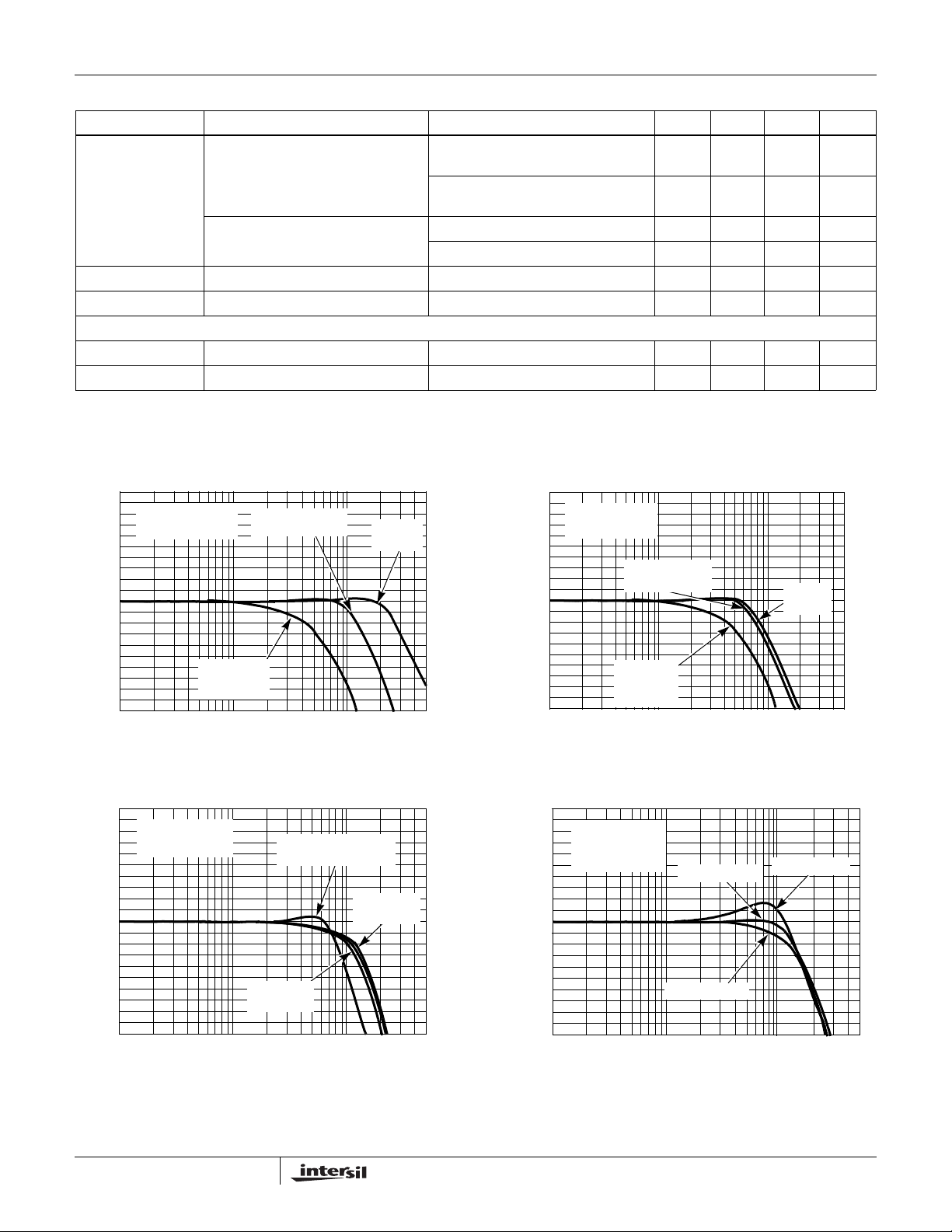
Typical Performance Curves V
10
V
8
6
4
2
0
-2
-4
NORMALIZED GAIN (dB)
-6
-8
-10
1M 10M 100M 500M
= 0.2V
OUT
RL = 150Ω
P-P
AV=4
R
R
FIGURE 1. SMALL SIGNAL GAIN vs FREQUENCY for
VARIOUS GAINS
AV = 2
R
= RG = 475Ω
F
= 475Ω
F
= 158Ω
G
FREQUENCY (Hz)
= +5V, RL = 150Ω to GND, CL = 0.6pF, TA = 25°C, unless otherwise specified.
S
10
V
= 2V
OUT
RL = 150Ω
P-P
AV = 2
= RG = 475Ω
R
F
AV = 4
= 475Ω
R
F
= 158Ω
R
G
FREQUENCY (Hz)
A
= 1
V
RF = 0Ω
8
6
4
2
0
-2
-4
NORMALIZED GAIN (dB)
-6
-8
-10
1M 10M 100M 500M
FIGURE 2. LARGE SIGNAL GAIN vs FREQUENCY for
VARIOUS GAINS
AV = 1
= 0Ω
R
F
10
V
8
6
4
2
0
-2
-4
NORMALIZED GAIN (dB)
-6
-8
-10
1M 10M 100M 500M
= 2V
OUT
RL = 150Ω
P-P
FREQUENCY (Hz)
AV = 2
C
= 0.6pF
L
AV = 1
= 0.6pF to 22pF
C
L
AV = 2
= 22pF
C
L
FIGURE 3. LARGE SIGNAL GAIN vs FREQUENCY vs C
3
10
V
8
6
4
2
0
-2
-4
NORMALIZED GAIN (dB)
-6
-8
-10
1M 10M 100M 500M
L
FIGURE 4. SMALL SIGNAL GAIN vs RF, RG
= 0.2V
OUT
RL = 150Ω
AV = 2
P-P
RF = RG = 475Ω
RF = RG = 301Ω
FREQUENCY (Hz)
RF = RG = 1kΩ
FN6192.1
June 28, 2006

ISL4089
Typical Performance Curves V
0.2
AV = 2
= RG = 475
R
F
0.1
R
= 150
L
0
-0.1
-0.2
-0.3
-0.4
-0.5
NORMALIZED GAIN (dB)
-0.6
-0.7
-0.8
1M 10M 100M 1G
V
= 2V
OUT
FREQUENCY (Hz)
P-P
FIGURE 5. 0.1dB GAIN FLATNESS
1.05
1.0
0.95
0.9
V
= +5V, RL = 150Ω to GND, CL = 0.6pF, TA = 25°C, unless otherwise specified. (Continued)
S
0.025
0.02
OUT
= 0.2V
P-P
0.015
0.01
0.005
0
-0.005
-0.01
ERROR(%)
-0.015
NORMALIZED GAIN
-0.02
-0.025
0.01
0.08
0.06
0.04
0.02
0
-0.02
-0.04
-0.06
-0.08
-0.10
NORMALIZED PHASE (°)
05.0
V
= 0.6V
OUT
= 150
R
L
= 2
A
V
f = 3.58MHz
RF = RG = 475Ω
V
OUT
V
OUT
V
OUT
P-P
V
OUT
= 0.6V
= 0.3V
2.5 3.0 3.5 4.0 4.50.5 1.0 1.5 2.0
DC (V)
= 0.3V
P-P
P-P
P-P
FIGURE 6. DIFFERENTIAL GAIN - PHASE
4.0
V
V
= 0.2V
OUT
RF = RG = 475Ω
CG = 0.5pF
P-P
3.5
3.0
2.5
= 2V
OUT
= RG = 475Ω
R
F
CG = 0.5pF
P-P
0.85
0.8
0.75
OUTPUT VOLTAGE (V)
0.7
0.65
TIME (20ns/DIV)
FIGURE 7. SMALL SIGNAL TRANSIENT RESPONSE; A
60
50
40
30
20
VOLTAGE NOISE (nV/√Hz)
10
V
= 2
2.0
1.5
OUTPUT VOLTAGE (V)
1.0
0.5
0
TIME (20ns/DIV)
FIGURE 8. LARGE SIGNAL TRANSIENT RESPONSE; A
V
= 2
0
100 1k 10k 100k
FREQUENCY (Hz)
FIGURE 9. INPUT NOISE vs FREQUENCY
4
FN6192.1
June 28, 2006

V
ISL4089
Typical Performance Curves V
JEDEC JESD51-7 HIGH EFFECTIVE THERMAL
CONDUCTIVITY TEST BOARD
1
909mW
0.8
0.6
0.4
0.2
POWER DISSIPATION (W)
0
0 100 125 150
FIGURE 10. PACKAGE POWER DISSIP A TION vs AMBIENT
ISL4089
(8 LD SOIC) PIN NAME
θ
S
J
O
A
=
8
1
1
0
°
C
/
W
5025 75 85
AMBIENT TEMPERATURE (°C)
TEMPERATURE
EQUIVALENT
CIRCUIT DESCRIPTION
= +5V, RL = 150Ω to GND, CL = 0.6pF, TA = 25°C, unless otherwise specified. (Continued)
S
JEDEC JESD51-3 LOW EFFECTIVE THERMAL
CONDUCTIVITY TEST BOARD
0.7
0.6
625mW
θ
S
J
O
0.5
0.4
0.3
0.2
POWER DISSIPATION (W)
0.1
0
0 100 125 150
A
=
8
1
6
0
°
C
/
W
5025 75 85
AMBIENT TEMPERATURE (°C)
FIGURE 11. P ACKAGE POWER DISSIP ATION vs AMBIENT
TEMPERATURE
1 IN- Circuit 1 Video amplifier inverting input
2 N+ Circuit 1 Video amplifier non-inverting input
3V
REF
Circuit 1 Restore amplifier V
REF
input
4 HOLD Circuit 2 Hold/restore logic input. Logic “0” selects the restore state; logic “1” selects the hold state
5 GND Circuit 4 Ground
6 NIC Circuit 1 No internal connection
7V
OUT
Circuit 3 Video amplifier output
8 V+ Circuit 4 Positive power supply
+
V+
21k
IN
V-
LOGIC PIN
GND
CIRCUIT 1 CIRCUIT 2
V+
V+
CAPACITIVELY
COUPLED
ESD CLAMP
FN6192.1
June 28, 2006
CIRCUIT 3
OUT
GND
5
GND
CIRCUIT 4

ISL4089
AC Test Circuits
R
GRF
R
-
V
IN
50Ω
FIGURE 12A. VIDEO AMPLIFIER AC TEST CIRCUIT FOR 50Ω
V
IN
75Ω
FIGURE 12B. BACKTERMINATED TEST CIRCUIT FOR VIDEO
+
R
GRF
+
CABLE APPLICATION.
S
118Ω
C
L
1. HOLD INPUT = 1
R
75Ω
C
L
1. HOLD INPUT = 1
86.6Ω
S
TEST
EQUIPMENT
50Ω
TEST
EQUIPMENT
75Ω
Figure 12A illustrates the AC test circuit used to operate the
video amplifier into a 150Ω load while providing a 50Ω
matched impedance. Figure 12B illustrates the test circuit for
impedance matching to 75Ω test equipment.
Application Information
General
The ISL4089 implements the video DC-restore function
using a high performance gain adjustable video amplifier
and a nulling, sample-hold amplifier to establish a user
defined DC reference voltage at the video amplifier output. A
detailed description of the DC-restore function implemented
in the ISL4089 can be found in application note AN1089,
EL4089 and EL4390 DC-Restored Video Amplifier. The
ISL4089 performs the same function with the exception that
it is designed for single supply operation.
Video Amplifier Operation (Figure 13)
The ISL4089 video amplifier (A1) is voltage-feed, high
performance video amplifier designed for +5V operation.
The output stage is capable of swinging to within 10mV of
the negative rail. The differential input stage contains an
internal voltage reference that positions the non-inverting
input DC level (V1) to ~1.2V higher than the negative supply
rail. This offset ensures that the amplifier input DC level is
maintained within the common mode input voltage range.
The amplifier non-inverting gain is given in Equation 1.
R
⎛⎞
V
OUT
V
IN+
1.2V–()1
F
--------+
•=
⎜⎟
R
⎝⎠
G
(EQ. 1)
DC-Restore Amplifier (Figure 13)
The DC-restore circuit contains a voltage reference amplifier
and an analog switch function that closes the DC-restore
loop under control of the HOLD logic input. The reference
amplifier uses an internal 10mV offset voltage (V2) to enable
the V
amplifier output stage operates in a current-feed mode with a
source/sink capability of ±300µA (Typ).
A logic “0” at the HOLD input closes switch S1 which closes
the DC-restore loop. The video input AC coupling capacitor,
CX1, acts as a DC hold capacitor (through the 75Ω
termination resistor RX1) to average the current-source
output of amplifier A2. When the DC-restore loop has
reached equilibrium, the DC voltage stored on CX1 will the
value required to force the output voltages at A1 (V
A2 (V
V
OUT
and; the DC voltage at the non-inverting input of the video
amplifier A1 is given in Equation 3:
V
IN+VOUT
Therefore, if V
the DC voltage stored on CX1 is ~1.2V.
The CX1 capacitor value is chosen from the system
requirements. A typical DC-restore application using the
horizontal sync to drive the HOLD pin will result in a 62µs
hold time. The typical input bias current to the video amplifier
is 1.2µA, so for a 62µs hold time, and a 0.01µF capacitor, the
output voltage drift is 7.5mV in one line. The restore amplifier
can provide a typical current of 300µA to charge capacitor
CX1, so with a 1.2µs sampling time, the output can be
corrected by 36mV in each line.
Using a smaller value of CX1 increases both the voltage that
can be corrected, as well as the droop while being held.
Likewise, using a larger value of CX1, reduces the correction
and droop voltages. A sample of charging and droop rates
are shown on the following table.
CAP VALUE
NOTE: Basic formulae are: V (droop) = Ib+ * (Line time - Sample
time)/Capacitor and V (charge) = I
input to sense down to the negative supply. The A2
REF
) and
) according to the following:
IN+
(DC) V
TABLE OF CHARGE STORAGE CAPACITOR VS DROOP
(if)
10 7.5 36 120
33 2.3 11 36
100 0.75 3.6 12
10mV+=
REF
(DC) 1.2V+=
is set to 0V (GND); V
REF
CHARGING RATES (NOTE)
DROOP IN
62µs
(mV)
CHARGE IN
OUT
OUT
1.2µs
(mV)
* Sample time/Capacitor
OUT
(EQ. 2)
(EQ. 3)
= 10mV, and
CHARGE IN
4µs
(mV)
6
FN6192.1
June 28, 2006

ISL4089
VIDEO
INPUT
RX1
75Ω
R
G
475Ω
CX1
-
V
Ref
0V to +4.5V
R
F
475Ω
V
IN-
V
IN+
V
REF
10mV
-
+
+
V2
FIGURE 13. BASIC +5V APPLICATION CIRCUIT
S1
+
A2
1.2V
+
-
V1
-
TTL
INPUT
A1
+
HOLD
ISL4089
4k
40pF
GND
V+
V
OUT
0.1µF
RXT
75Ω
4.7µF
VIDEO
OUT
+5V
GND
Using the Reference Voltage Input (V
REF
)
Implementing DC-restore and amplifying composite video
using a single +5V supply amplifier, requires attention to the
performance of the amplifier over the minimum to maximum
range of output voltage swing. The differential gain - phase
plot in Figure 6 shows the amplifier accuracy operating from
a single +5V supply, driving a 300mV
and a 600mV
P-P
P-P
signal into a 150Ω load. Over the output DC voltage range of
0.5V to 3.25V, differential gain and phase are less than
0.05% and 0.05° respectively and defines the optimum
output voltage range of the ISL4089. Figure 6 also shows
that as the signal level increases, a corresponding decrease
in the output DC level (min/max voltage swing) can be
expected. The V
input enables the output DC voltage
REF
level to be optimally programmed within the min/max voltage
range, according to Equation 2. The values in Figure 6 take
into account the additional amplifier overhead (300mV
and 600mV
) needed by the video signal. Although the
P-P
P-P
AC performance degrades below ~0.5V, the ISL4089
maintains DC accuracy down to 10mV .
Limiting the Output Current
No output short circuit current limit exists on these parts. All
applications need to limit the output current to less than
60mA. Adequate thermal heat sinking of the parts is also
required.
Application Information
A typical single supply application circuit using the EL1883
sync separator to generate the DC-restore hold command, is
shown in Figure 13. The ISL4089 is configured for a gain of
2, and 75
driving; providing an end to end gain of 1. DC-restore is
performed during sync tip using the composite sync output
of the EL1883, which clamps the -300mV input sync tip level
to 0VDC at the ISL4089 output (Figure 15 - lower trace).
Clamping sync tip to 0VDC forces the black level, color burst
and active video to the +300mV level at the 75Ω load in the
terminal equipment, and to +600mV at the ISL4089 output
pin. The +600mV DC offset is safely within the lower linear
range of the ISL4089 output (Figure 6 - Differential Gain Phase) and the 2V maximum video amplitude at the output
is safely within the upper limit. In applications where the sync
tip level can’t be guaranteed, positioning the active video
within the linear range can be accomplished using the back
porch clamp output of the EL1883 and supplying +1V to the
V
REF
the +1V V
sync tip level to pass through to the output.
Ω
input and output terminations are used for cable
input. This has the effect of clamping the back porch to
level at the output while enabling the negative
REF
7
FN6192.1
June 28, 2006

VIDEO
VIDEO
INPUT
INPUT
Composite Sync
Composite Sync
Out
Out
Vertical Sync
Vertical Sync
Out
Out
475 ohms
475 ohms
R3
R3
75 ohms
75 ohms
C5
C5
0.1uF
0.1uF
R4
R4
0.01uF
0.01uF
ISL4089
R5
R5
475 ohms
475 ohms
+5V
4.7uF
4.7uF
Out
Out
Out
Out
C1
C1
+5V
Ground
Ground
Out
Out
ISL4089
1
1
1
IN-
IN-
C4
C4
IN-
2
2
2
IN+
IN+
IN+
3
3
3
Vref
Vref
Vref
4
4
4
Hold
Hold
Hold
EL1883
1
1
1
2
2
2
3
3
3
4
4
4
EL1883
ISL4089
-
-
+
+
C2, C3
R6
R6
75 ohms
75 ohms
C6
C6
0.056 uF
0.056 uF
C2, C3
0.1uF
0.1uF
Back-porch Clamp
Back-porch Clamp
Horizontal Sync
Horizontal Sync
V+
V+
V+
-
-
+
+
Vout
Vout
Vout
NC
NC
NC
GND
GND
GND
8
8
8
7
7
7
6
6
6
5
5
5
R7
R7
681K
681K
FIGURE 14. APPLICATION CIRCUIT USING THE EL1883 SYNC SEPARATOR TO GENERATE DC-RESTORE HOLD CONTROL
COMPOSITE VIDEO INPUT
0VDC
COMPOSITE SYNC INPUT
0VDC
DC-RESTORED VIDEO OUTPUT
0VDC
FIGURE 15. DC-RESTORE USING COMPOSITE SYNC AND V
REF
= 0VDC
8
FN6192.1
June 28, 2006

Small Outline Package Family (SO)
A
D
NN
(N/2)+1
ISL4089
h X 45°
PIN #1
E
C
SEATING
PLANE
0.004 C
E1
B
0.010 BM CA
I.D. MARK
1
e
0.010 BM CA
(N/2)
c
SEE DETAIL “X”
L1
H
A2
GAUGE
PLANE
A1
b
DETAIL X
L
4° ±4°
MDP0027
SMALL OUTLINE PACKAGE FAMILY (SO)
SYMBOL SO-8 SO-14
(0.150”)
A 0.068 0.068 0.068 0.104 0.104 0.104 0.104 MAX -
A1 0.006 0.006 0.006 0.007 0.007 0.007 0.007 ±0.003 A2 0.057 0.057 0.057 0.092 0.092 0.092 0.092 ±0.002 -
b 0.017 0.017 0.017 0.017 0.017 0.017 0.017 ±0.003 -
c 0.009 0.009 0.009 0.011 0.011 0.011 0.011 ±0.001 D 0.193 0.341 0.390 0.406 0.504 0.606 0.704 ±0.004 1, 3
E 0.236 0.236 0.236 0.406 0.406 0.406 0.406 ±0.008 -
E1 0.154 0.154 0.154 0.295 0.295 0.295 0.295 ±0.004 2, 3
e 0.050 0.050 0.050 0.050 0.050 0.050 0.050 Basic L 0.025 0.025 0.025 0.030 0.030 0.030 0.030 ±0.009 -
L1 0.041 0.041 0.041 0.056 0.056 0.056 0.056 Basic -
h 0.013 0.013 0.013 0.020 0.020 0.020 0.020 Reference -
N 8 14 16 16 20 24 28 Reference -
NOTES:
1. Plastic or metal protrusions of 0.006” maximum per side are not included.
2. Plastic interlead protrusions of 0.010” maximum per side are not included.
3. Dimensions “D” and “E1” are measured at Datum Plane “H”.
4. Dimensioning and tolerancing per ASME Y14.5M-1994
SO16
SO16 (0.300”)
(SOL-16)
SO20
(SOL-20)
SO24
(SOL-24)
SO28
(SOL-28) TOLERANCE NOTES
A
0.010
Rev. L 2/01
All Intersil U.S. products are manufactured, assembled and tested utilizing ISO9000 quality systems.
Intersil Corporation’s quality certifications can be viewed at www.intersil.com/design/quality
Intersil products are sold by description only. Intersil Corporation reserves the right to make changes in circuit design, software and/or specifications at any time without
notice. Accordingly, the reader is cautioned to verify that data sheets are current before placing orders. Information furnished by Intersil is believed to be accurate and
reliable. However, no responsibility is assumed by Intersil or its subsidiaries for its use; nor for any infringements of patents or other rights of third parties which may result
from its use. No license is granted by implicat ion or oth erwise u nde r any p a tent or p at ent r ights of Intersil or its subsidiaries.
For information regarding Intersil Corporation and its products, see www.intersil.com
9
FN6192.1
June 28, 2006
 Loading...