

查询ISL36356A-APDK供应商
®
ISL36356A-APDK
Data Sheet February 2003
PRISM® 11Mbps Wireless Local Area
Network Access Point
The Intersil ISL36356A WLAN
Access Point is a complete wireless
high speed Network Access Point
(AP) utilizing the Intersil PRISM® AP
Direct Sequence Spread Spectrum Wireless Transceiver
chip set. It provides a complete PRISM reference design
platform of hardware and software to system providers or
integrators requiring wireless data communications
capability . The Open Source Linux operating system off ers a
flexible and extensible development platform for making
customized Access Points and Gateways.
The Developers Kit includes a WLAN Access Point reference
design, configuration application, source code and
documentation. It supports the IEEE802.11b network
specification for Direct Sequence Spread Spectrum DSSS
signaling, providing data rates of 1, 2, 5.5 and 11Mbps.
Typical operating ranges are shown in Table 1.
TABLE 1. TYPICAL OPERATING RANGE*
DATA RATE (Mbps) INDOOR RANGE OUTDOOR RANGE
11 120 feet (37 meters) 500 feet (152 meters)
5.5 200 feet (61 meters) 800 feet (243 meters)
2 240 feet (73 meters) 1300 feet (396 meters)
1 300 feet (91 meters) 1750 feet (533 meters)
* The range will vary in different operating environments due to
effects such as building construction.
Ordering Information
PART NUMBER DESCRIPTION INCLUDED
ISL36356A-APDK-EVAL WLAN Evaluation Kit 1 AP
1 PC card
Packaging
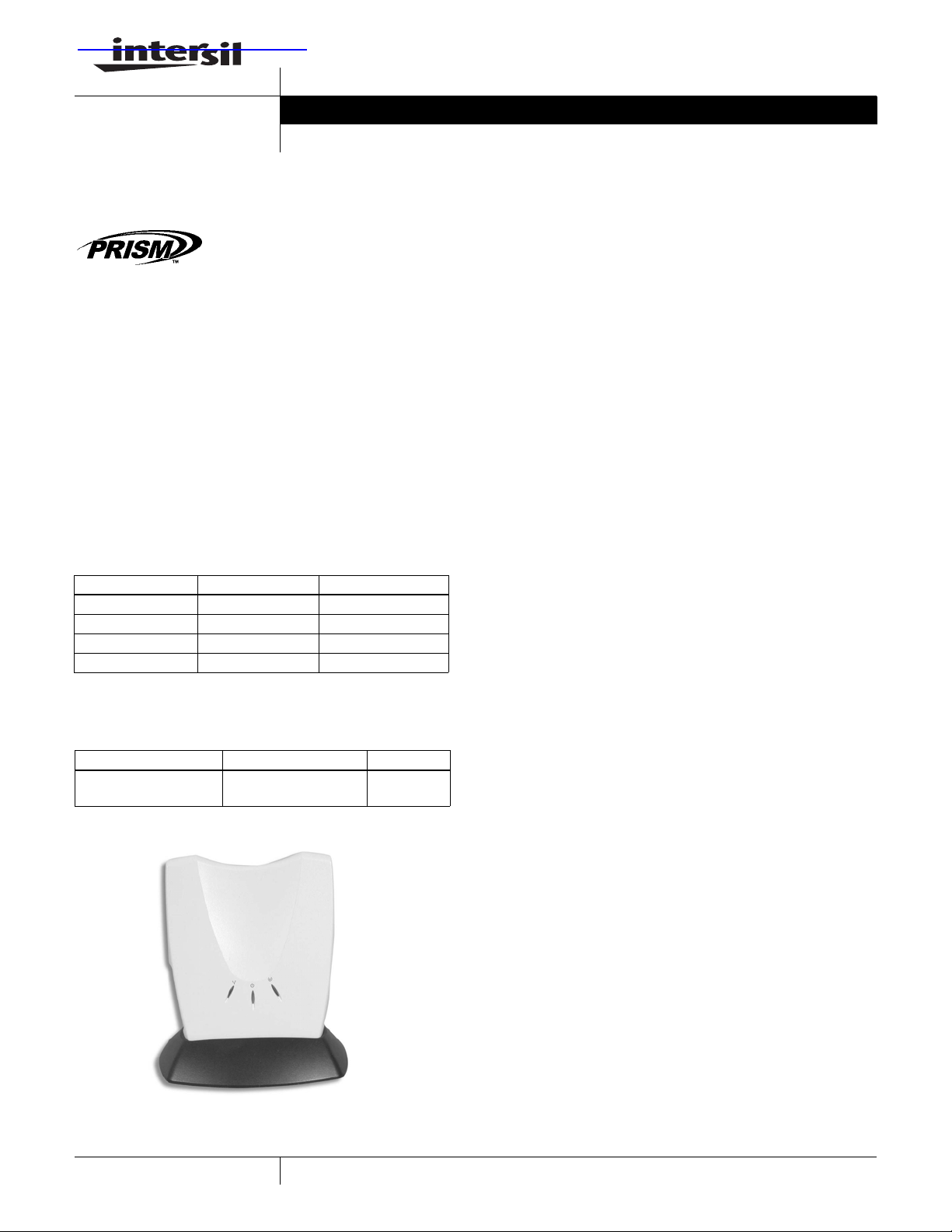
FIGURE 1. SAMPLE PLASTIC ENCLOSURE
FN9048.3
Features
• Supports the lEEE802.11b Direct Sequence Specification
• FCC Certified Under Part 15 to Operate in 2.4GHz ISM Band
• ETSI EN 300 328 parts 1 and 2 and
• ETSI EN 301 489 parts 1 and 17 Certified
• Supports All Features Required for Wi-Fi Compliant
Access Points
• Support for 11, 5.5, 2 and 1Mbps Data Rates
• Supports Dual Antenna Diversity
• Supports Short Preamble
• Advanced RAKE Receiver Design with Decision Feedback
Equalizer
• Provided Wired ethernet (802.3) connection supports both
10/100BaseT speeds
• Open Source Linux operating system
• Wi-Fi Protected Access (WPA) as well as Wired Equivalent
Privacy (WEP) 64&128
•802.1x Security
• Wizard for Automated IP Configuration
• Wireless Distribution System (WDS) provides repeater and
bridging functionality
References
For Intersil documents available on the internet, see web site
http://www .intersi l.com/
[1] TB337 Tech Brief, Intersil Corporation, “A Brief T utorial on
Spread Spectrum and Packet Radio”.
[2] AN9850 Application Note, Intersil Corporation,
“Complementary Code Keying Made Simple”.
[3] AN9829 Application Note, Intersil Corporation, “Brief Tutorial
on IEEE802.11 Wireless LANs”.
[4] AN9820 Application Note, Intersil Corporation, “A
Condensed Review of Spread Spectrum T echniques for
ISM Band Systems”.
[5] 555006, Intersil Corporation, "The uClinux Development
Environment".
[6] 555007, Intersil Corporation, "Porting Guide for the Intersil
Access Point".
[7] 555012, Intersil Corporation, "Architecture of a Linux based
Intersil AP".
[8] 555050, Intersil Corporation, “MVC Software Interface
Manual”.
[9] 555053, Intersil Corporation, “AP Developer's Kit End User
Manual”.
[10] 555051, Intersil Corporation, “AP Developer’s Kit
Customization - User’s Manual”.
[11] AN1007, Intersil Corporation, “Introduction to the Wireless
Distribution System (WDS) and Features”.
[12] 555029, Intersil Corporation, “Reference Manual APDK
Web Server Interface Design”.
Further information can be found in the following:
uClinux homepage: http://www.uclinux.org/
1
Copyright © Intersil Americas Inc. 2003. All Rights Reserved. All other trademarks mentioned are the property of their respective owners.
PRISM® is a registered trademark of Intersil Americas Inc. PRISM and design is a trademark of Intersil Americas Inc.
CAUTION: These devices are sensitive to electrostatic discharge; follow proper IC Handling Procedures.
1-888-INTERSIL or 321-724-7143
| Intersil (and design) is a registered trademark of Intersil Americas Inc.
ISL36356A-APDK
Absolute Maximum Ratings Operating Conditions
Supply Voltage. . . . . . . . . . . . . . . . . . . . . . . . . . -0.3V to 7.5V (Max)
Storage Temperature (Note 1) . . . . . . . . . . . . . . . . . . -20
Caution: These are the absolute maximum ratings for the product. Exceeding these limits could cause permanent damage to the AP.
NOTE:
1. All temperature references refer to ambient conditions.
o
C to 85oC
Temperature Range . . . . . . . . . . . . . . . . . . . . . . . . .0
Supply Voltage Range. . . . . . . . . . . . . . . . . . . . . . . . . . 4.5V to 5.5V
o
C ≤ TA ≤ 50oC
Electrical Specifications Test Conditions: Supply Voltage (V
Unless Otherwise Specified
PARAMETER SYMBOL TEST CONDITIONS MIN TYP MAX UNITS
CURRENT CONSUMPTION
Initialization Current I
Continuous Transmit Mode I
Continuous Receive Mode I
RF SYSTEM SPECIFICATIONS
Transmitter Power Output P
Receive Sensitivity RX_S 1Mbps, BER 8 E-5 - -93
Multipath Delay Spread using Naftali
model
CC
CC
CC
T
DELAY
Receiving Valid Packets - 516 - mA
out
2Mbps,BER 8 E-5 - -89
5.5Mbps,BER 8 E-5 - -87
11Mbps, BER 8 E-5 - -83
2Mbps,BER 8 E-5 - >290 - ns
5.5Mbps, BER 8 E-5 - 200 - ns
) = 5V, Ambient Temperature (TA) = 25oC,
CC
- 517 - mA
- 670 - mA
14.8 16.2 17.0 dBm
(Note 2)
(Note 2)
(Note 2)
(Note 2)
-dBm
-dBm
-dBm
-dBm
11Mbps, BER 8 E-5 - 105 - ns
Maximum Receive Level RX_MAX BER 8 E-5 -3 >2 - dBm
Third Order Intercept Point (Input) IIP3_90 -90 dBm input - -3 - dBm
IIP3_25 -25 dBm input - +20 - dBm
Carrier Suppression TX_sup Test Mode - 43 - dB
Image Rejection IR BER 8E-5 - 65 - dB
IF Rejection IFR BER 8E-5 60 66 - dB
Adjacent Channel Rejection (Note 3) ACR BER 8E-5 - 35 - dB
Data Rate (Physical Layer) Rate - 1, 2, 5.5
and 11
NOTES:
2. Measurements done on antenna port 1. Antenna port 2, 1 to 2 dB better performance.
3. The adjacent channel measurement is carried out on two antennas separated by 25MHz (five channels). The -70dBm desired signal and variable
strength jammer are both 11Mbps DSSS data transmissions. The jammer is a continuous waveform with -40dBc first sidelobes.
- Mbps
2

ISL36356A-APDK
Functional Overview
The WLAN Access Point is designed to operate in the
2.4GHz ISM frequency band, channels 1 to 11, as specified
by the FCC in the USA. The AP will also operate on
channels 12 through 14, where permitted by local regulatory
authorities. Radio equipment must be certified in a country
prior to use. Refer to Table 4 for a list of countries and
agencies that have approved the ISL36356A-APDK for
operation.
The Intersil PRISM II Chip Set allows for high level
integration; providing reduced size, increased throughput,
improved radio performance and faster time to market. The
WLAN Access Point implements Direct Sequence Spread
Spectrum DSSS technology that provides superior noise and
signal jamming immunity; including less severe impact from
unintentional radiators such as microwave ovens. By using
an Access Point, the wireless LAN can be set up to allow an
even greater number of users to interconnect, and to
increase the coverage area. The wireless LAN can be easily
connected into an existing wired LAN, allowing for easy
expansion of the service.
The ISL3856 Media Access Controller
(MAC) Protocol Handler
The ISL3856 ARM940 based MAC Processor and the MAC
Virtual Coprocessor (MVC) firmware are responsible for
running the IEEE802.11 protocol in the WLAN AP. The MVC
acts as a software emulated coprocessor to the ARM940
and runs completely separated from the operating system. It
provides an abstraction layer of the underlying hardware to
the operating system via a well-defined interface.
The MVC supports the following 802.11 functions:
• CSMA/CA (Carrier Sense Multiple Access with Collision
Avoidance) with Random Backoff
• WEP Security
• Short/Long Preamble with multirate
• RTS/CTS Handshake (Ready To Send/Clear To Send)
• MAC Level Acknowledgments (Media Access Control)
• Re-Transmission of Unacknowledged Frames
• Duplicate Detection and Rejection
• Broadcast and Multicast Frames
• Fragmentation and Re-Assembly
• Supports clients Power save mode
extensible platform for f eature dev elopment. Due to the large
availability of different Linux based applications in the Open
Source community, it is easy to add new features to the AP,
reducing time to market.
A special embedded version of the Linux operating system,
uClinux, is running on the ISL3856. It is tailored to run on the
ARM940 processor and optimized for size. The uClinux
Application Programmers Interface (API) is the same as the
standard Linux API. The ISL36356A platform offers the
following basic functions:
• DHCP client/server
• Configuration via Web Interface and SNMP
• Simple and Failsafe Firmware Upgrade via Web Interface
• Wi-Fi Protected Access (WPA)
•802.1x Security
• Wireless Distribution System
• Routing, NAPT and firewall support
• PPPoE
• VPN Passthrough (PPTP)
• 802.1d Spanning Tree Protocol (STP)
Adding features to the development platform can be done by
taking applications that are available in the Open Source
community and port them to the platform. Porting
documentation is available to assist in this task. Applications
can also be made from scratch, so they can be kept closed
source.
The table below lists the resources that are available for
adding new applications to the basic design. In normal
operation, approximately 50% of the processor cycles of the
ARM940 are consumed by the MVC. The remaining capacity
is available for Linux and the applications. Because all
applications are stored in Flash in a compressed format, the
available Flash is calculated for both compressed and
uncompressed files.
TABLE 2. AVAILABLE RESOURCES
AVAILABLE FLASH
MEMORY
CONFIGURATION
2Mbyte Flash
8Mbyte RAM
4Mbyte Flash
16Mbyte RAM
AVAILABLE
RAM
~1.2Mbyte ~16kbyte / 32kbyte
~9.2Mbyte ~2.0Mbyte / 4.0Mbyte
(COMPRESSED /
UNCOMPRESSED)
• Timestamp Synchronization
• DCF (Distributed Coordination Function)
The Linux Operating System
The ARM940 based MAC processor hosts a complete Open
Source Linux operating system, offering a flexible and
3
For starting development on the Linux based platform, a
complete dev e l o pment environment is shipped with th e
product, including documentation describing the setup of a
development system.
The complete hardware and software of the system are
pretested which ensures a stable development platform.

ISL36356A-APDK
Configuration Wizard
To ease the process of configuring the Access Point, a
Microsoft Windows 95, 98, 2000, NT, XP wizard is included
that can be customized to fit specific needs. It automatically
detects an AP in the network, even if it is misconfigured, and
can configure the IP settings in all common environments
(DHCP, auto IP and fixed IP). After the IP settings are
configured correctly, it starts the Web interface to finish the
configuration.
WPA Overview
WiFi Protected Access (WPA) provides two security
enhancements to wireless LANs: improved data encryption
and user authentication.
To improve data encryption, WPA uses a Temporal Key
Integrity Protocol (TKIP). This protocol provides per-packet
key mixing, a message integrity check (MIC) called Michael,
an extended initialization vector (IV) with sequencing rules,
and a re-keying mechanism.
For user authentication, WPA implements 802.1X and th e
Extensible Authentication Protocol (EAP) to provide a
framework for strong user authentication. This framework
utilizes a central authentication server, such as RADIUS, to
authenticate each user on the network before they join it,
and also employs "mutual authentication" so that the
wireless user does not accidentally join a rogue network that
might steal its network credentials.
In networks in which there is no authentication server or EAP
framework, WPA runs in a special Pre-Shared Key (PSK)
mode. In this mode, similar to the current WEP environment,
a station and access point use the same manually-entered
key to establish an association. Once this key is verified,
WPA then encrypts frames using TKIP to provide improved
security .
4

ISL36356A-APDK
Block Diagram
ISL3856 MAC
See “The ISL3856 Media Access Controller (MAC) Protocol
Handler” section.
BBP ISL3863
The BaseBand Processor uses CCK modulation and a Rake
architecture to reduce the effects of multipath. This reduces
the error rates in typical office environments to improve
overall data throughput.
IF HFA3783
The IF is a linear design with AGC. This permits the use of
equalizers in the BBP. An IF overload detector and
selectable low gain LNA mode work with the BBP to extend
dynamic range without sacrificing sensitivity. The IF LO
frequency is generated by an external VCO. Filtering at the
IF is done by a SAW BandPass filter.
HFA3683 / HFA3983 RF
The RF IC’s are produced in advanced SiGe technology to
realize improvements in integration, performance, and power
consumption. Integral PLL’s in both RF and IF parts eliminate
the need for an external synthesizer. The HFA3683’s internal
LNA noise figure is improved so that an external LNA IC is
no longer needed. The chipset is designed so that the parts
can be interfaced with few external components.
The RF LO frequency is generated by an external VCO. The
PA incorporates an integral power detector that is monitored
by the BBP. The BBP controls the IF gain to maintain
constant output levels.
Antenna System
A dual spatial integrated antenna system is used to select
the most optimal signal. The antennas are sleeved dipoles
directly connected to the PCB.
FIGURE 2. ISL36356A-APDK BLOCK DIAGRAM
...
MVC
PHY
I/O
RADIO
I/O
Parallel
802 .11
Protocol
handling
2Mx8 or
4Mx8
FLASH
4Mx16or
8Mx16
SDRAM
SNMP
TCP/ IP
Stack
Bridging Layer
MVC Driver
CONTROL
DMA
CTRL
DHCP
SW WEP
ENGINE
Ethernet
MAC
ISL3856
MAC
Applications
Linux
OS
16MHz
Ethernet
PHY
STATUS
LEDS
5

ISL36356A-APDK
IEEE802.11 International Agreement and
Frequency Assignments
The IEEE802 LAN committee has forged an international
agreement providing for wireless data communication
standards for the frequency range of 2.4GHz to 2.4835GHz,
as allocated by the FCC in the USA, and in the 2.400GHz to
2.497GHz frequency range, as specified by the regulatory
authority in Japan. These standards are designed to focus
the industry to develop highly integrated, low cost,
interoperable WLAN equipment, of which the ISL36356AAPDK is a prime example.
In the U.S., there are 11 channels specified by the FCC in
the 2.412GHz to 2.462GHz range. In Japan, channel 14 at
2.484GHz is authorized under ARIB STD-33 and channels
1–13 are authorized under ARIB STD-T66. The ETSl
(European) regulatory body conforms to the USA (FCC)
channel assignments with the exception that channels 12
and 13 are also allowed. Some countries in Europe, notably
France hav e unique channel restrictions.
Although information contained in Table 3 is deemed to be
accurate, local regulatory authorities should be consulted
before using such equipment.
The available channels of operation in the 2.4GHz to
2.4835GHz and 2.471GHz to 2.497GHz ranges are as follows:
TABLE 3. IEEE802.11 CHANNELS
CHANNEL
NUMBER
1 2412MHz US, CA, EU, JP
2 2417MHz US, CA, EU, JP
3 2422MHz US, CA, EU, JP
4 2427MHz US, CA, EU, JP
5 2432MHz US, CA, EU, JP
6 2437MHz US, CA, EU, JP
7 2442MHz US, CA, EU, JP
8 2447MHz US, CA, EU, JP
9 2452MHz US, CA, EU, JP
10 2457MHz US, CA, EU, JP, FR
11 2462MHz US, CA, EU, JP, FR
12 2467MHz EU, FR, JP
13 2472MHz EU, FR, JP
14 2484MHz JP (see note)
KEY: US = United States, CA = Canada, EU = European countries
(except France), FR = France, JP = Japan
NOTE: channel 14 operation in Japan requires Japan filter to be
enabled in order to comply with ARIB STD-33.
CHANNEL
FREQUENCY
GEOGRAPHIC
USAGE
The ISL36356A-APDK is shipped with FCC-compliant
firmware. In order to ensure regulatory-compliant channel
usage in a particular country, special geographic-specific
firmware is available for customer production assemblies
which restricts channel usage. Examples include ETSIcompliant firmware, etc. For Japan, a Japan filter is
implemented to comply with ARIB STD-33. Since the end
user does not have the ability to alter this firmware,
regulatory compliance is ensured.
Agency and Regulatory Body Approvals
The WLAN Access Point will comply to the standards shown
in Table 4:
TABLE 4. COMPLIANCE STANDARDS
COUNTRY APPROVAL NOTES
USA FCC part 15,
Sec. 15.247,
Sec. 15.107 and 15.109
Canada ICAN RSS-210 Designed for
EU & EFTA EN 60950
EN 301 489-1 V1.2.1 (2000-08)
EN 301 489-17 V1.1.1 (2000-09)
EN 300 328 Part 1 V1.2.2 (2000-07)
EN 300 328 Part 2 V1.1.1 (2000-07)
Japan ARIB STD-T66
ARIB STD-33
Grant obtained
compliance
Certified under
RTTE directive
Designed for
compliance
FCC Information to User
This product does not contain any user serviceable
components and is to be used with approved antennas only.
Any product changes or modifications will invalidate all
applicable regulatory certifications and approvals.
FCC Electronic Emission Notices
This device complies with Part 15 of the FCC Rules.
Operation is subject to the following two conditions:
1. This device may not cause harmful interference
2. This device must accept any interference received,
including interference that may cause undesired
operation.
FCC Radio Frequency Interference statement
This equipment has been tested and found to comply with
the limits for a class B digital device, pursuant to Part 15 of
the FCC Rules. These limits are designed to provide
reasonable protection against harmful interference when the
equipment is operated in a commercial environment. This
equipment generates, uses and can radiate radio frequency
energy and, if not installed and used in accordance with the
instructions, may cause harmful interference to radio
communications.
6

ISL36356A-APDK
Operation of this equipment in a residential area may cause
harmful interference in which case the user will be required
to correct the interference at his own expense.
If this equipment does cause harmful interference to radio or
television reception, which can be determined by turning the
equipment off and on, the user is encouraged to try to
correct the interference by one or more of the following
measures:
• Reorient or relocate the receiving antenna.
• Increase the separation between the equipment and
receiver.
• Connect the equipment into an outlet on a circuit different
from that to which the receiver is connected.
• Consult the dealer or an experienced radio/TV technician
for help.
FCC Guidelines for Human Exposure
The EIRP was measured for the lower, middle and highest
frequencies used by the transmitter. The results in Table 5
are based on a safe distance between antenna and
operator of eight inches.The equipment therefore fulfills the
requirements on power density for general population /
uncontrolled exposure of 1.0mW/cm
complies with the requirements of FCC Part 15.247 (b) (4)
and FCC OET Bulletin 65 including supplements A, B and C.
TABLE 5. POWER DENSITY CALCULATION
Ch.1 Ch.6 Ch.11
Measured EIRP
(mW)
Calculated Power
Density (mW/cm2)
WARNING: Any changes or modifications of equipment not expressly
approved by Inter sil could void the user’s authority to operate the equipment.
Caution:To comply with FCC RF exposure limits, a separation distance of at
least 20cm must be maintained between the antenna’s of this device and all
persons.
63.8 66.2 69.3
0.051 0.053 0.055
2
and therefore
All Intersil U.S. products are manufactured, assembled and tested utilizing ISO9000 quality systems.
Intersil Corporation’s quality certifications can be viewed at www.intersil.com/design/quality
Intersil products are sold by description only. Intersil Corporation reserves the right to make changes in circuit design, software and/or specifications at any time without
notice. Accordingly, the reader is cautioned to verify that data sheets are current before placing orders. Information furnished by Intersil is believed to be accurate and
reliable. However, no responsibility is assumed by Intersil or its subsidiaries for its use; nor for any infringements of patents or other rights of third parties which may result
from its use. No license is granted by implication or otherwise under any patent or pat en t rights of In t ersil or its sub sidi aries.
For information regarding Intersil Corporation and its products, see www.intersil.com
7
 Loading...