

Intersil ISL284xxEVAL1Z Series User Manual
®
ISL284xxEVAL1Z Evaluation Board User’s Guide
Application Note July 23, 2007
Introduction
The ISL284xxEVAL1Z evaluation board is a design platform
containing all the circuitry needed to characterize critical
performance parameters of the ISL28470 quad
instrumentation amplifier using a variety of user defined test
circuits.
The ISL284xx are quad operational amplifiers featuring low
noise, low distortion, and rail-to-rai l output drive capability.
They are designed to operate with single and dual supplies
from +5VDC (±2.5VDC) down to +2.4VDC (±1.2VDC).
Reference Documents
• ISL28476 Data Sheet, FN6301
• ISL28478 Data Sheet, FN6339
• ISL28486 Data Sheet, FN6312
• ISL28488 Data Sheet, FN6339
Evaluation Board Key Features
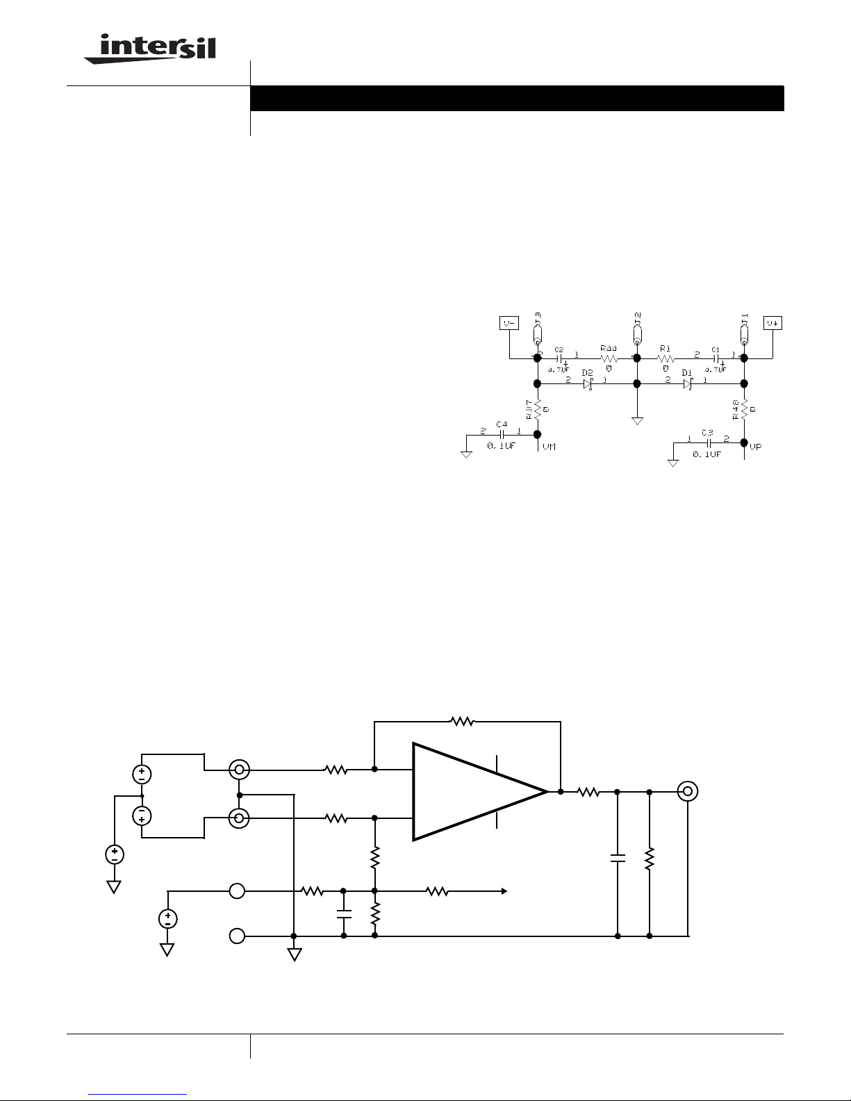
AN1339.0
supply operation, the V
the power supply negative terminal. For split supplies +V
and V
terminals connect to their respective power supply
-
terminals. De-coupling capacitors C
GND through R
1
are 0Ω but can be changed by the user to provide additional
power supply filtering, or to reduce the voltage rate-of-rise to
less than ±1V/µs. Anti-reverse diodes D
circuit in the case of accidental polarity reversal.
V- V+
1
R37
C4
12
FIGURE 1. POWER SUPPLY CIRCUIT
and GND pins are tied together to
-
and C2, connect to
1
and R2, 0Ω resistors. Resistors R3 and R4
and D2 protect the
1
J3
VM
C2
4.7UF
0
J2
R44
12
D2
2
1
R1 C1
1
00
D1
21
4.7UF
C3
12
0.1UF
J1
1
12
0
R48
VP
The ISL284xxEVAL1Z is designed to enable the IC to
operate from a single supply (+2.4VDC to +5VDC), or from
split supplies (±1.2VDC to ±2/5V). The board is configured
for 4 independent op amps connected for differential input
with a closed loop gain of 10. A single external reference
voltage (VREF) pin and provisions for a user-selectable
voltage divider (filter is included).
Power Supplies (Figure 1)
RIN-
10kΩ
RIN+
10kΩ
+
, V-
External power connections are made through the V
and GND connections on the evaluation board. For single
IN(A,B,C,D)-
IN-
IN+
IN(A,B,C,D)+
VCM
VREF
VREF
GND
0Ω
+
IN-
-
IN+
+
RREF(A,B,C,D)+
100kΩ
10kΩ
0Ω
Amplifier Configuration (Figure 2)
The schematic of each of the 4 op amps with the
components supplied is shown in Figure 2. The circuit
implements a differential input-amp with a closed loop gain
of 10. The circuit can operate from a single 2.4VDC to
+5VDC supply, or from dual supplies from ±1.2VDC to
±2.5VDC. The VREF pin can be connected to ground to
establish a ground referenced input for split supply
operation, or can be externally set to any reference level for
single supply operation.
RF
100kΩ
VP
V+
V-
VM
TO OTHER CHANNELS
1/4 ISL284xx
0Ω
VOUT(x)
10kΩ
1
FIGURE 2. BASIC AMPLIFIER CONFIGURATION
CAUTION: These devices are sensitive to electrostatic discharge; follow proper IC Handling Procedures.
1-888-INTERSIL or 1-888-468-3774
| Intersil (and design) is a registered trademark of Intersil Americas Inc.
All other trademarks mentioned are the property of their respective owners.
Copyright Intersil Americas Inc. 2007. All Rights Reserved
Application Note 1339
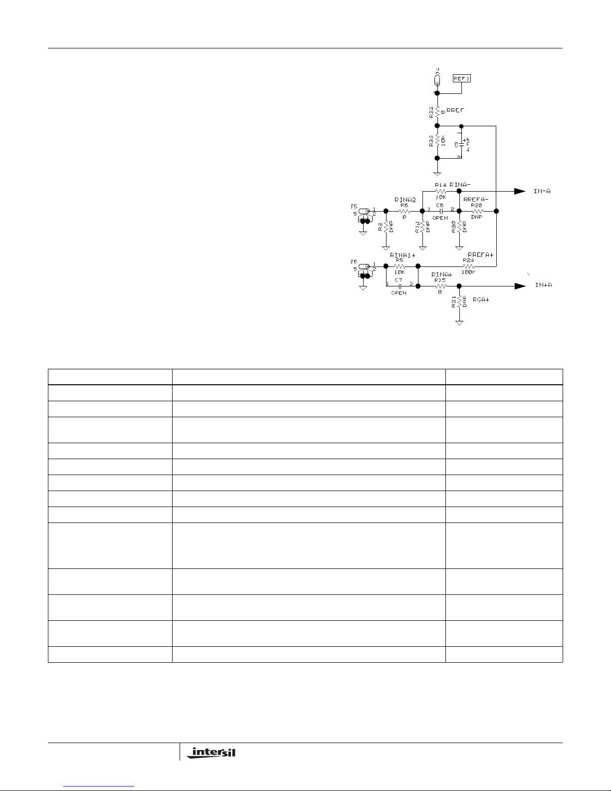
User-selectable Options (Figure 3)
Component pads are included to enable a variety of
user-selectable circuits to be added to the amplifier inputs,
the VREF input, and the amplifier feedback loops. A voltage
divider and filter option can be added to establish a power
supply-tracking common mode reference at the VREF input.
The inverting and non-inverting inputs have additional
resistor placements for adding input attenuation, or to
establish input DC offsets through the VREF pin.
.
J4
REF1
1
RREF
0
R32
12
10K
R33
C5
4.7UF
RINA-
R14
IN(A,B,C,D)-
J5
5
3
4
IN(A,B,C,D)+
J6
5
3
4
1
2
0
RINA2-
R2
DNP
RINA1+
R5
1
2
10K
C7
12
OPEN
10K
C6R6
12
OPEN
DNP
R11
RINA+
R15
0
R20
R21
RREFA-
R28
DNP
DNP
RREFA+
R24
100K
RGA+
DNP
FIGURE 3. COMPONENT-SELECTABLE OPTIONS
IN-A
IN+A
ISL284xxEVAL1Z Components Parts List
DEVICE NUMBER DESCRIPTION COMMENTS
C1, C2, C5 CAP-TANTALUM, SMD, D, 4.7µF, 50V, 10% LOW ESR, ROHS Power Supply Decoupling
C3, C4 CAP, SMD, 0603, 0.1µF, 25V, 10%, X7R, ROHS Power Supply Decoupling
C6-C25 CAP, SMD, 0603, DNP-PLACE HOLDER, ROHS User selectable capacitors - not
populated
D1, D2 DIODE-RECTIFIER, SMD, SOD-123, 2P, 40V, 0.5A, ROHS Reverse Power Protection
U1 (ISL28476EVAL1Z) ISL28476FAZ, IC-RAIL-TO-RAIL PRECISION OP AMP, 16P, QSOP, ROHS
U1 (ISL28478EVAL1Z) ISL28478FAZ, IC-RAIL-TO-RAIL PRECISION OP AMP, 16P, QSOP, ROHS
U1 (ISL28486EVAL1Z) ISL28486FAZ, IC-RAIL-TO-RAIL PRECISION OP AMP, 16P, QSOP, ROHS
U1 (ISL28488EVAL1Z) ISL28488FAZ, IC-RAIL-TO-RAIL PRECISION OP AMP, 16P, QSOP, ROHS
R2-R4, R11-R13, R20-R23, R25,
R26, R28, R30, R31, R34, R38,
R42, R43, R46, R55-R58,
R59-R62
R6, R8, R10, R15, R17, R19, R36,
R41, R51-R54, R63-R66
R5, R7, R9, R14, R16, R18, R33,
R35, R40, R67-R70
R24, R27, R29, R39, R45, R47,
R49, R50
R1, R32, R37, R44, R48 RES, SMD, 0805, 0Ω, 1/8W, TF, ROHS 0Ω user selectable resistors
RESISTOR, SMD, 0603, 0.1%, MF, DNP-PLACE HOLDER User selectable resistors - not
populated
RES, SMD, 0603, 0Ω, 1/16W,TF, ROHS 0Ω user selectable resistors
RES, SMD, 0603, 10k, 1/10W, 1%, TF, ROHS RG gain resistors
RES, SMD, 0603, 100k, 1/10W, 1%, TF, ROHS RF gain resistors
2
AN1339.0
July 23, 2007
 Loading...