

HS-1840ARH-T
Data Sheet July 1999 File Number
Radiation Hardened 16 Channel CMOS
Analog Multiplexer with High-Z Analog
Input Protection
Intersil’sSatellite Applications FlowTM(SAF) devices are fully
tested and guaranteed to 100kRAD Total Dose. These QML
Class T devices are processed to a standard flow intended
to meet the cost and shorter lead-time needs of large
volume satellite manufacturers, while maintaining a high
level of reliability.
The HS-1840ARH-T is a Radiation Hardened, monolithic 16
channel multiplexer constructed with the Intersil Rad-Hard
Silicon Gate, Dielectric Isolation process. It is designed to
provide a high input impedance to the analog source if
device power fails (open), or the analog signal voltage
inadvertently exceeds the supply by up to ±35V, regardless
of whether the device is powered on or off. Selection of one
of sixteen channels is controlled by a 4-bit binary address
plus an Enable-Inhibit input, which conveniently controls the
ON/OFF operation of severalmultiplexers in a system. All
inputs have electrostatic discharge protection.
Specifications
Specifications for Rad Hard QML devices are controlled by
the Defense Supply Center in Columbus (DSCC). The SMD
numbers listed below must be used when ordering.
Detailed Electrical Specifications for the HS-1840ARH-T
are contained in SMD 5962-95630. A “hot-link” is provided
from our website for downloading.
www.intersil.com/spacedefense/ne wsafc lasst.asp
Intersil’s Quality Management Plan (QM Plan), listing all
Class T screening operations, is also available on our
website.
www.intersil.com/quality/manuals.asp
4589.1
Features
• QML Class T, Per MIL-PRF-38535
• Radiation Performance
5
- Gamma Dose (γ) 1 x 10
RAD(Si)
- No Latch-Up, Dielectrically Isolated Device Islands
• Improved r
DS(ON)
Linearity
• Improved Access Time 1.5µs (Max) Over Temp and Rad
• High Analog Input Impedance 500MΩ During Pow er Loss
(Open)
• ±35V Input Over Voltage Protection (Power On or Off)
• Excellent in Hi-Rel Redundant Systems
• Break-Before-Make Switching
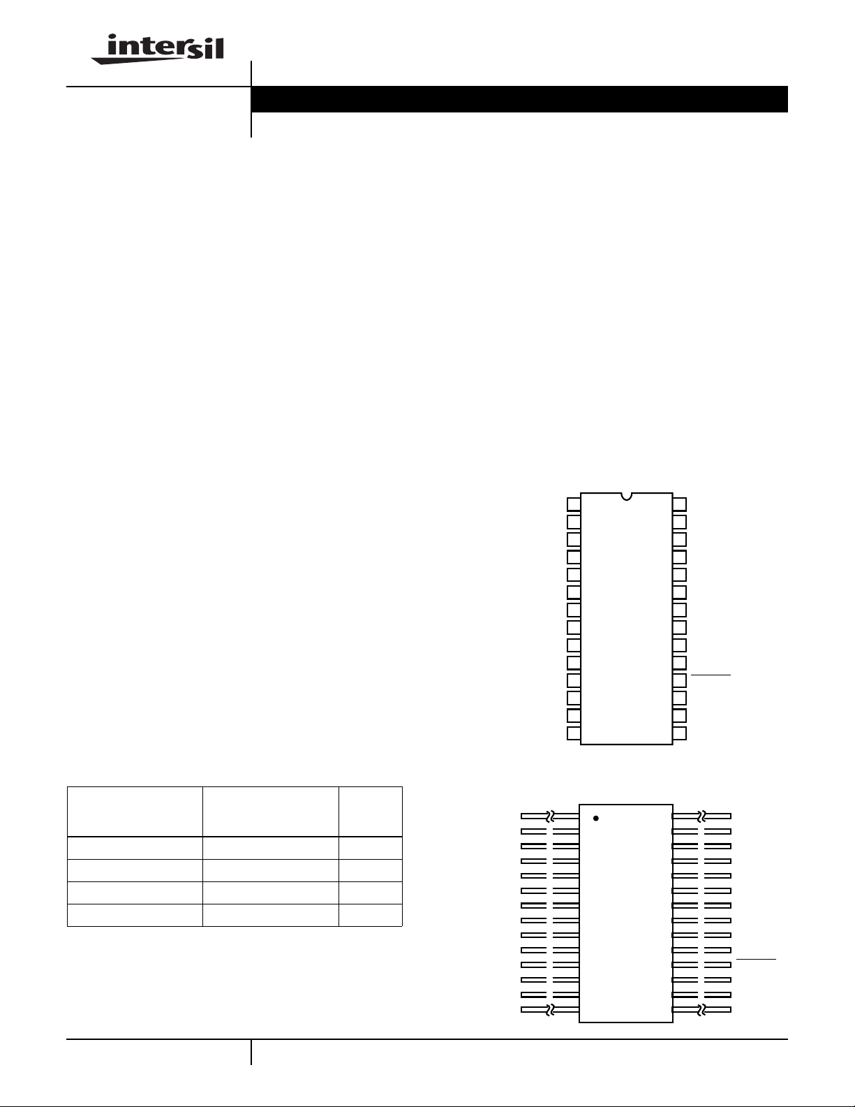
Pinouts
HS1-1840ARH-T (SBDIP), CDIP2-T28
TOP VIEW
28
27
26
25
24
23
22
21
20
19
18
17
16
15
OUT
-V
S
IN 8
IN 7
IN 6
IN 5
IN 4
IN 3
IN 2
IN 1
ENABLE
ADDR A0
ADDR A1
ADDR A2
(+5V
ADDR A3
+V
1
S
NC
2
3
NC
4
IN 16
5
IN 15
6
IN 14
7
IN 13
8
IN 12
9
IN 11
10
IN 10
IN 9
11
12
GND
) V
REF
13
14
S
Ordering Information
TEMP.
ORDERING
NUMBER
5962R9563002TXC HS1-1840ARH-T -55 to 125
HS1-1840ARH/Proto HS1-1840ARH/Proto -55 to 125
5962R9563002TYC HS9-1840ARH-T -55 to 125
HS9-1840ARH/Proto HS9-1840ARH/Proto -55 to 125
NOTE:
Minimumorderquantity for -T is 150 units through
distribution, or 450 units direct.
PART
NUMBER
1
RANGE
(oC)
CAUTION: These devices are sensitive to electrostatic discharge; follow proper IC Handling Procedures.
HS9-1840ARH-T (FLATPACK) CDFP3-F28
TOP VIEW
+V
S
NC
NC
IN 16
IN 15
IN 14
IN 13
IN 12
IN 11
IN 10
IN 9
GND
) V
(+5V
S
REF
ADDR A3
www.intersil.com or 407-727-9207
Satellite Applications Flow™ (SAF) is a trademark of Intersil Corporation.
1
2
3
4
5
6
7
8
9
10
11
12
13
14
28
27
26
25
24
23
22
21
20
19
18
17
16
15
| Copyright © Intersil Corporation 1999
OUT
-V
S
IN 8
IN 7
IN 6
IN 5
IN 4
IN 3
IN 2
IN 1
ENABLE
ADDR A0
ADDR A1
ADDR A2
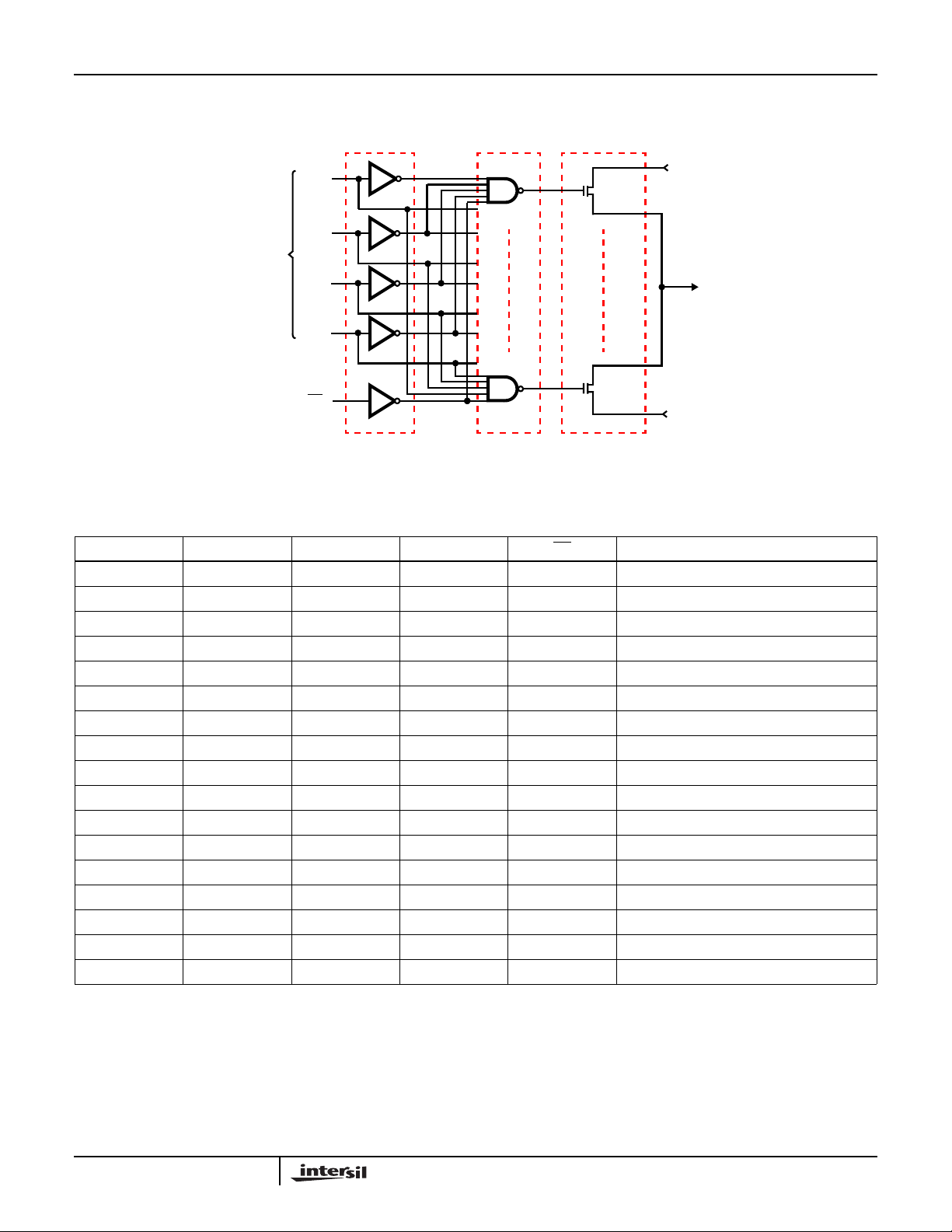
Functional Diagram
HS-1840ARH-T
IN 1
OUT
IN 16
DIGITAL
ADDRESS
A0
A1
A2
A3
EN
BUFFER AND
LEVEL SHIFTER
1
16
DECODERSADDRESS INPUT
P
P
MULTIPLEX
SWITCHES
TRUTH TABLE
A3 A2 A1 A0 EN “ON” CHANNEL
XXXXH None
LLLLL 1
LLLHL 2
LLHLL 3
LLHHL 4
LHLLL 5
LHLHL 6
LHHLL 7
LHHHL 8
HLLLL 9
HLLHL 10
HLHLL 11
HLHHL 12
HHLLL 13
HHLHL 14
HHHL L 15
HHHHL 16
2

Die Characteristics
HS-1840ARH-T
DIE DIMENSIONS:
(2820µm x 4080µm x 483µm ±25.4µm)
111 x 161 x 19mils ±1mil
METALLIZATION:
Type: Al Si Cu
Thickness: 16.0k
Å ±2kÅ
SUBSTRATE POTENTIAL:
Unbiased (DI)
BACKSIDE FINISH:
Silicon
Metallization Mask Layout
IN7
IN8
IN6
HS-1840ARH-T
IN5
PASSIVATION:
Type: Nitride (Si
) over Silox (SiO2)
3N4
Nitride Thickness: 4.0k
Silox Thickness: 12.0kű1.3kÅ
WORST CASE CURRENT DENSITY:
< 2.0e5 A/cm
2
TRANSISTOR COUNT:
407
PROCESS:
Radiation Hardened Silicon Gate, Dielectric Isolation
IN4
IN3
IN2
Å ±0.5kÅ
IN1
ENABLE
OUT
+V
IN16
A0
-V
A1
A2
A3
V
REF
GND
IN15
IN14
IN13
IN12
IN11
IN10
IN9
All Intersil semiconductor products are manufactured, assembled and tested under ISO9000 quality systems certification.
Intersil semiconductor products are sold by description only. Intersil Corporation reserves the right to make changes in circuit design and/or specifications at any time without notice. Accordingly, the reader is cautioned to verify that data sheets are current before placing orders. Information furnished by Intersil is believed to be accurate and
reliable. However ,no responsibility is assumed by Intersil or its subsidiaries for its use; nor for any infringements of patents or other rights of third parties which may result
from its use. No license is granted by implication or otherwise under any patent or patent rights of Intersil or its subsidiaries.
For information regarding Intersil Corporation and its products, see web site http://www.intersil.com
3
 Loading...