

Intersil Corporation HM-6504 Datasheet
HM-6504
March 1997
Features
• Low Power Standby. . . . . . . . . . . . . . . . . . . 125µW Max
• Low Power Operation . . . . . . . . . . . . . 35mW/MHz Max
• Data Retention . . . . . . . . . . . . . . . . . . . . . . . at 2.0V Min
• TTL Compatible Input/Output
• Three-State Output
• Standard JEDEC Pinout
• Fast Access Time. . . . . . . . . . . . . . . . . . 120/200ns Max
• 18 Lead Package for High Density
• On-Chip Address Register
• Gated Inputs - No Pull Up or Pull Down Resistors
Required
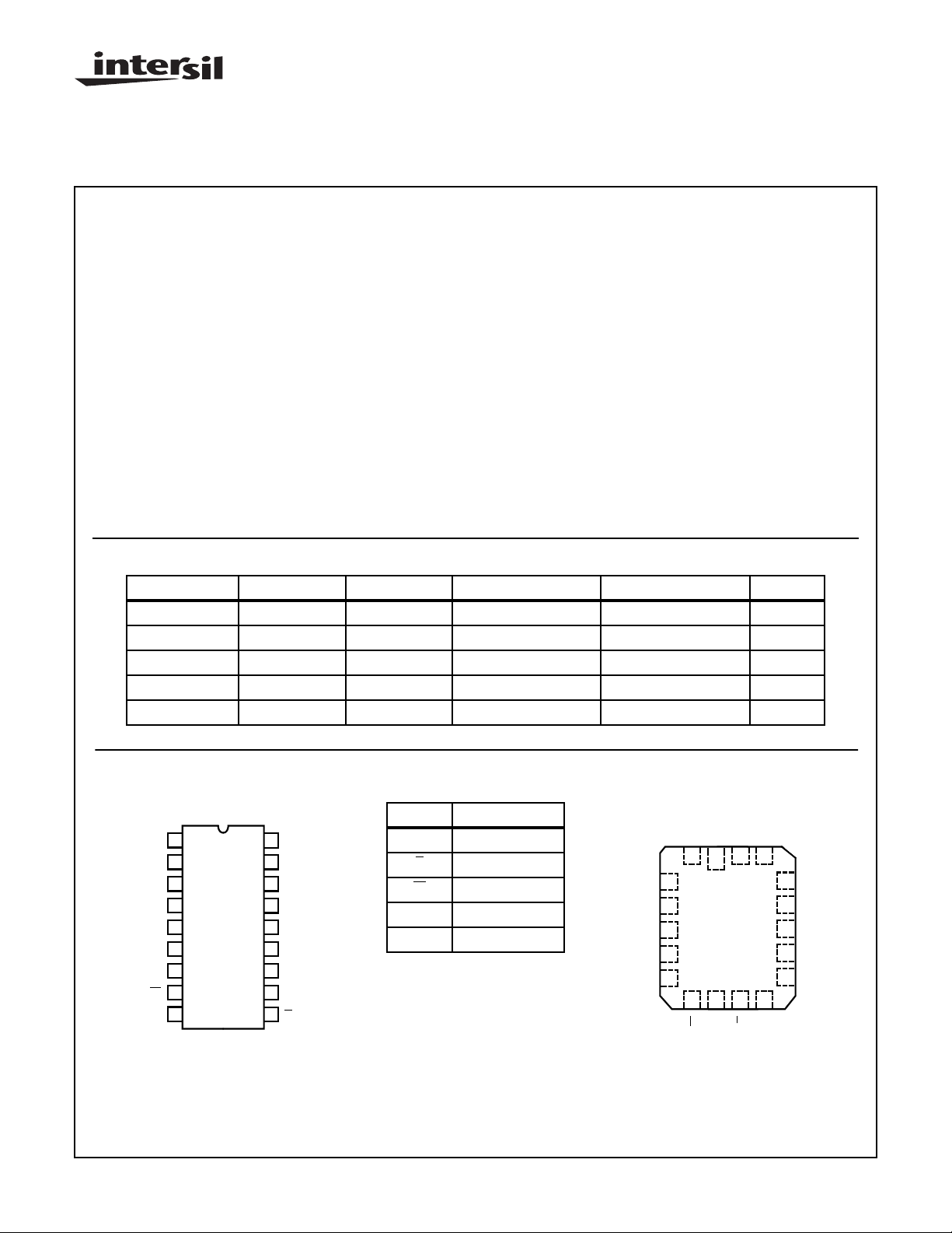
Ordering Information
120ns 200ns 300ns TEMP. RANGE PACKAGE PKG. NO.
- HM3-6504B-9 HM3-6504-9 -40oC to +85oC PDIP E18.3
HM1-6504S-9 HM1-6504B-9 HM1-6504-9 -40oC to +85oC CERDIP F18.3
24501BVA - - - JAN # F18.3
810240IVA 8102403VA 8102405VA - SMD # F18.3
- - HM4-6504-9 -40oC to+85oC CLCC J18.B
4096 x 1 CMOS RAM
Description
The HM-6504 is a 4096 x 1 static CMOS RAM fabricated
using self-aligned silicon gate technology. The device utilizes
synchronous circuitry to achieve high performance and low
power operation.
On-chip latches are provided for addresses, data input and
data output allowing efficient interfacing with microprocessor
systems. The data output can be forced to a high impedance
state for use in expanded memory arrays.
Gated inputs allow lower operating current and also eliminate the need for pull up or pull down resistors. The
HM-6504 is a fully static RAM and may be maintained in any
state for an indefinite period of time.
Data retention supply voltage and supply current are guaranteed over temperature.
Pinouts
HM-6504 (PDIP, CERDIP)
TOP VIEW
1
A0
2
A1
3
A2
4
A3
5
A4
6
A5
7
Q
8
W
9
GND
CAUTION: These devices are sensitive to electrostatic discharge; follow proper IC Handling Procedures.
http://www.intersil.com or 407-727-9207
18
V
CC
17
A6
16
A7
15
A8
14
A9
13
A10
12
A11
11
D
10
E
| Copyright © Intersil Corporation 1999
PIN DESCRIPTION
A Address Input
E Chip Enable
W Write Enable
D Data Input
Q Data Output
6-126
A2
A3
A4
A5
3
4
5
6
7
Q
HM-6504 (CLCC)
TOP VIEW
CC
A0A1V
21 17
18
8 9 10 11
ND
E
W
File Number 2994.1
A6
16
A7
15
A8
14
A9
13
A10
12
A11
D

Functional Diagram
HM-6504
LSB
A8
A7
A6
A0
A1
A2
D
W
E
LATCHED
ADDRESS
REGISTER
L
D
LATCH
L
L
LATCH
A
A
6
6
QD
Q
GATED
ROW
DECODER
G
D
LATCH
64
Q
L
G
A
L
LSB A11 A5 A4 A3 A9 A10
NOTES:
13. All lines active high-positive logic.
14. Three-state Buffers: A high → output active.
15. Control and Data Latches: L low → Q = D and Q latches on rising edge of L.
16. Address Latches: Latch on falling edge of E.
17. Gated Decoders: Gate on rising edge of G.
64 x 64
MATRIX
64
GATED COLUMN
DECODER AND
DATA I/O
6
A
LATCHED
ADDRESS
REGISTER
6
A
D
LATCH
L
Q
Q
A
6-127
HM-6504
Absolute Maximum Ratings Thermal Information
Supply Voltage . . . . . . . . . . . . . . . . . . . . . . . . . . . . . . . . . . . . .+7.0V
Input, Output or I/O Voltage . . . . . . . . . . . GND -0.3V to VCC +0.3V
ESD Classification . . . . . . . . . . . . . . . . . . . . . . . . . . . . . . . . Class 1
CAUTION: Stresses above those listed in “Absolute Maximum Ratings” may cause permanent damage to the device. This is a stress only rating and operation
of the device at these or any other conditions above those indicated in the operational sections of this specification is not implied.
Operating Conditions
Operating Voltage Range . . . . . . . . . . . . . . . . . . . . . +4.5V to +5.5V Operating Temperature Range
Thermal Resistance (Typical) θ
CERDIP Package . . . . . . . . . . . . . . . . 75oC/W 15oC/W
PDIP Package. . . . . . . . . . . . . . . . . . . 75oC/W N/A
CLCC Package . . . . . . . . . . . . . . . . . . 90oC/W 33oC/W
Maximum Storage Temperature Range . . . . . . . . .-65oC to +150oC
Maximum Junction Temperature
Ceramic Package . . . . . . . . . . . . . . . . . . . . . . . . . . . . . . . +175oC
Plastic Package. . . . . . . . . . . . . . . . . . . . . . . . . . . . . . . . . +150oC
Maximum Lead Temperature (Soldering 10s). . . . . . . . . . . . +300oC
JA
θ
JC
Die Characteristics
Gate Count . . . . . . . . . . . . . . . . . . . . . . . . . . . . . . . . . . .6910 Gates
HM-6504S-9, HM-6504B-9, HM-6504-9 . . . . . . . .-40oC to +85oC
HM-6504B-8, HM-6504-8 . . . . . . . . . . . . . . . . . .-55oC to +125oC
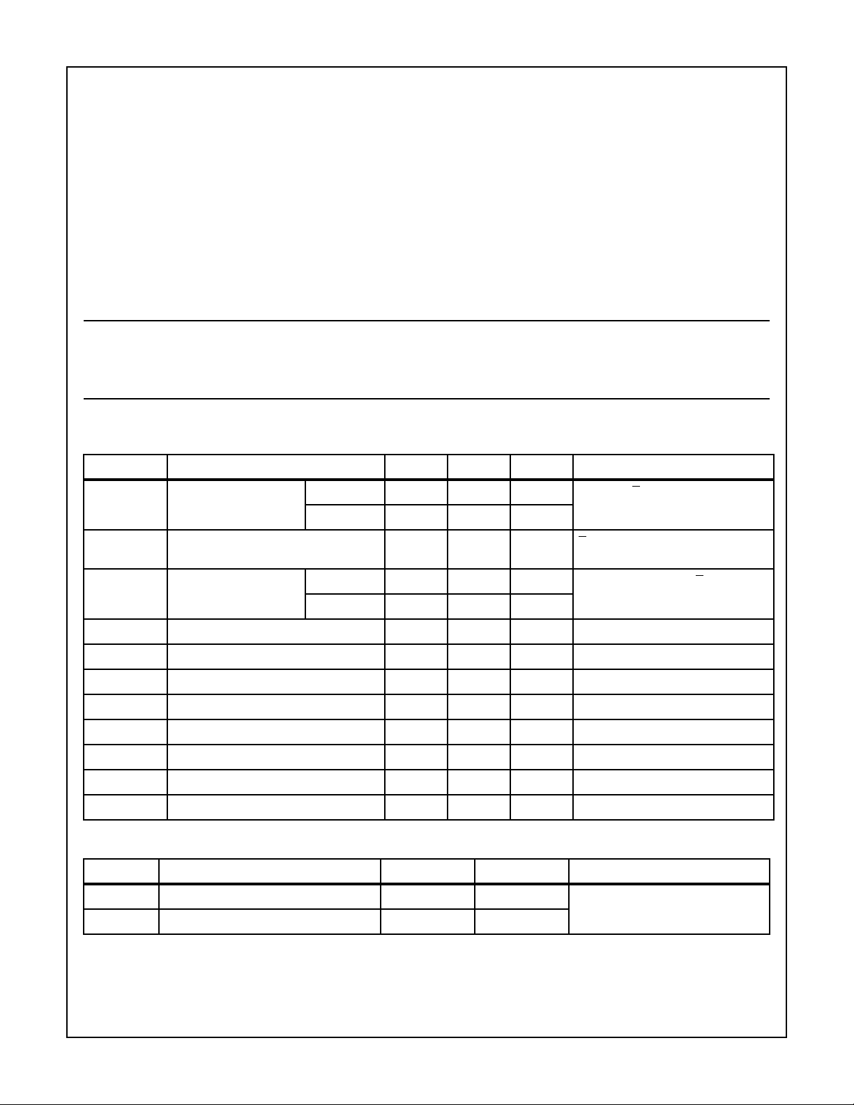
DC Electrical Specifications V
SYMBOL PARAMETER MIN MAX UNITS TEST CONDITIONS
ICCSB Standby Supply Current HM-6504-9 - 25 µA IO = 0mA, E = VCC -0.3V,
ICCOP Operating Supply
Current (Note 1)
ICCDR Data Retention Supply
Current
VCCDR Data Retention Supply Voltage 2.0 - V
II Input Leakage Current -1.0 +1.0 µA VI = VCC or GND, VCC = 5.5V
IOZ Output Leakage Current -1.0 +1.0 µA VO = VCC or GND, VCC = 5.5V
VIL Input Low Voltage -0.3 0.8 V VCC = 4.5V
VIH Input High Voltage VCC -2.0 VCC +0.3 V VCC = 5.5V
VOL Output Low Voltage - 0.4 V IO = 2.0mA, VCC = 4.5V
VOH1 Output High Voltage 2.4 - V IO = -1.0mA, VCC = 4.5V
VOH2 Output High Voltage (Note 2) VCC -0.4 - V IO = -100µA, VCC = 4.5V
= 5V ±10%; TA = -40oC to +85oC (HM-6504B-9, HM-6504-9)
CC
TA = -55oC to +125oC (HM-6504B-8, HM-6504-8)
HM-6504-8 - 50 µA
-7mAE = 1MHz, IO = 0mA, VI = GND,
HM-6504-9 - 15 µA IO = 0mA, VCC = 2.0V, E = V
HM-6504-8 - 25 µA
VCC = 5.5V
VCC = 5.5V
CC
Capacitance T
SYMBOL PARAMETER MAX UNITS TEST CONDITIONS
CI Input Capacitance (Note 2) 8 pF f = 1MHz, All measurements are
CO Output Capacitance (Note 2) 10 pF
NOTES:
1. Typical derating 5mA/MHz increase in ICCOP.
2. Tested at initial design and after major design changes.
= +25oC
A
referenced to device GND
6-128
 Loading...