

S
N
G
I
®
F
D
E
D
N
E
M
M
O
C
E
R
T
O
N
L
E
E
Data Sheet August 1, 2005
E
S
E
N
R
O
6
6
5
7
W
S
E
D
EL7556D
FN7339.1
Integrated Adjustable 6 Amp
Synchronous Switcher
The EL7556D is an adjustable synchronous DC:DC
switching regulator optimized for a 5V input and 1.0V-3.8V
output. By combining integrated NMOS power FETS with a
fused-lead package, the EL7556D can supply up to 6A
continuous output current without the use of external power
devices or discrete heat sinks, thereby minimizing design
effort and overall system cost.
On-chip resistorless current sensing is used to achieve
stable, highly efficient, current-mode control. The EL7556D
also incorporates the VCC2DET function to directly interface
with the Intel P54 and P55 microprocessors. Depending on
the state of VCC2DET, the output voltage is internally preset
to 3.5V or a user-adjustable voltage using two external
resistors. In both internal and external feedback modes the
active-high PWRGD output indicates when the regulator
output is within ±10% of the programmed voltage. An onboard sensor monitors die temperature (OT) for overtemperature conditions and can be connected directly to
OUTEN to provide automatic thermal shutdown. Adjustable
oscillator frequency and slope compensation allow added
flexibility in overall system design.
The EL7556D is available in a 28-pin SO package and is
specified for operation over the full -40°C to +85°C
temperature range.
Ordering Information
PART
NUMBER PACKAGE
EL7556DCM 28-Pin SO - MDP0027
EL7556DCM-T13 28-Pin SO 13” MDP0027
EL7556DCMZ
(See Note)
EL7556DCMZ-T13
(See Note)
NOTE: Intersil Pb-free plus anneal products employ special Pb-free
material sets; molding compounds/die attach materials and 100%
matte tin plate termination finish, which are RoHS compliant and
compatible with both SnPb and Pb-free soldering operations. Intersil
Pb-free products are MSL classified at Pb-free peak reflow
temperatures that meet or exceed the Pb-free requirements of
IPC/JEDEC J STD-020.
28-Pin SO
(Pb-free)
28-Pin SO
(Pb-free)
TAPE &
REEL PKG. DWG. #
- MDP0027
13” MDP0027
Features
• Improved temperature and voltage ranges
• 6A continuous load current
• Precision internal 1% reference
• 1.0V to 3.8V output voltage
• Internal power MOSFETs
• >90% efficiency
• Synchronous switching
• Adjustable slope compensation
• Over-temperature indicator
• Pulse-by-pulse current limiting
• Operates up to 1MHz
• 1.5% typical output accuracy
• Adjustable oscillator with sync
• Remote enable/disable
• Intel P54- and P55-compatible
• VCC2DET interface
• Internal soft-start
• Pb-free plus anneal available (RoHS compliant)
Applications
• PC motherboards
• Local high power CPU supplies
• 5V to 1.0V DC:DC conversion
• Portable electronics/instruments
• P54 and P55 regulators
• GTL+ Bus power supply
1
CAUTION: These devices are sensitive to electrostatic discharge; follow proper IC Handling Procedures.
1-888-INTERSIL or 1-888-468-3774
| Intersil (and design) is a registered trademark of Intersil Americas Inc.
Copyright Intersil Americas Inc. 2003, 2005. All Rights Reserved
All other trademarks mentioned are the property of their respective owners.
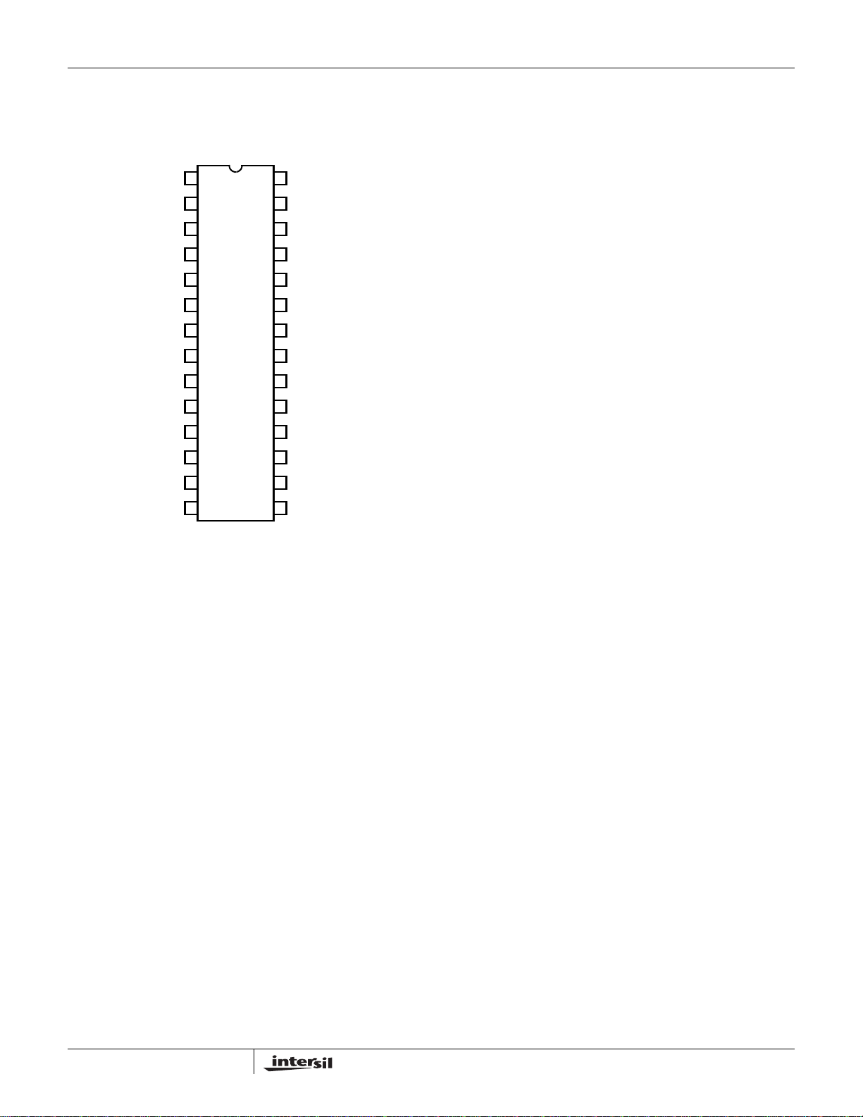
Pinout
EL7556D
EL7556D
(28-PIN SO)
TOP VIEW
1
2
3
4
5
6
7
8 21
9
10
11
12
13
14 15
28
FB2FB1
27
CPCREF
26
C2VCSLOPE
25
VSSCOSC
VHIVDD
24
LXVIN
23
LXVSSP
22
LXVIN
LXVSSP
20
VSSPVSSP
19
VSSPVSSP
18
TESTVSSP
17
PWRGDVCC2DET
16
OTOUTEN
2
EL7556D
Absolute Maximum Ratings (T
Storage Temperature Range . . . . . . . . . . . . . . . . . .-65°C to +150°C
Supply (V
Output Pins . . . . . . . . . . . . . . .-0.3V below GND, +0.3V above V
CAUTION: Stresses above those listed in “Absolute Maximum Ratings” may cause permanent damage to the device. This is a stress only rating and operation of the
device at these or any other conditions above those indicated in the operational sections of this specification is not implied.
IMPORTANT NOTE: All parameters having Min/Max specifications are guaranteed. Typ values are for information purposes only. Unless otherwise noted, all tests are
at the specified temperature and are pulsed tests, therefore: T
). . . . . . . . . . . . . . . . . . . . . . . . . . . . . . . . . . . . . . . . 6.0V
IN
Electrical Specifications V
DD
= 25°C)
A
= V
= 5V, C
IN
= TC = T
J
= 1nF, C
OSC
A
DD
SLOPE
Ambient Operating Temperature . . . . . . . . . . . . . . . . -40°C to +85°C
Operating Junction Temperature . . . . . . . . . . . . . . . . . . . . . . . 135°C
Peak Output Current . . . . . . . . . . . . . . . . . . . . . . . . . . . . . . . . . . .9A
= 470pF, TA = 25°C, unless otherwise specified.
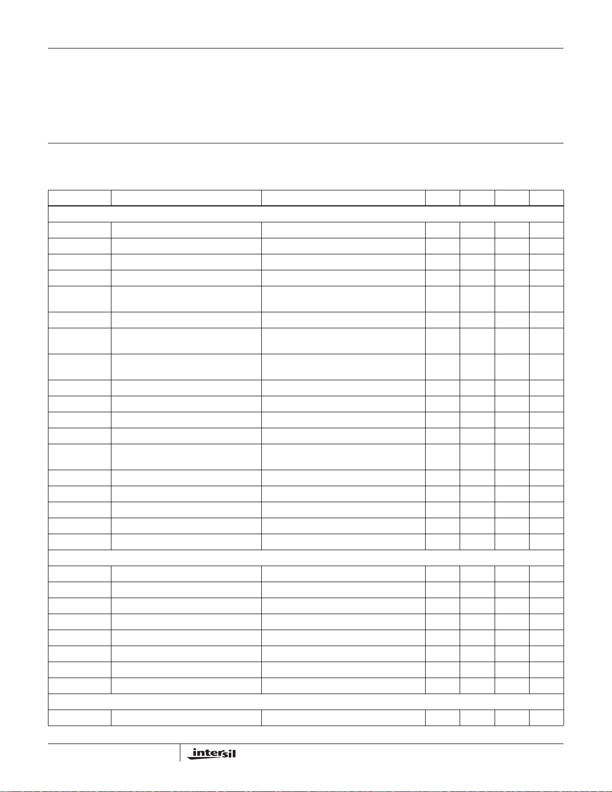
PARAMETER DESCRIPTION CONDITIONS MIN TYP MAX UNIT
GENERAL
I
DD
I
DDOFF
I
VIN
V
OUT1
V
OUT2
V
OUTLINE
V
OUTLOAD
VDD Supply Current OUTEN = 4V, F
= 120kHz 11 25 mA
OSC
VDD Standby Current OUTEN = 0 0.1 mA
V
No Load Current OUTEN = 0 3 5 mA
IN
Output Initial Accuracy VCC2DET = 4V, IL = 3A (see Fig. 1) 3.450 3.500 3.550 V
Output Initial Accuracy VCC2DET = 0V, IL = 3A, R3 = 150Ω, R4 =
2.450 2.500 2.550 V
100Ω (see Fig. 1)
Output Line Regulation VDD = 5V, ±10% -1 1 %
Output Load Regulation 0A < I
< 6A, relative to IL = 3A,
LOAD
-1 1 %
continuous mode of operation (see Fig.1)
R
SHORT
I
I MAX
V
OUTTC
T
OT
T
HYS
V
PWRGD
V
DDOFF
V
DDON
V
HYS
M
SS
D
MAX
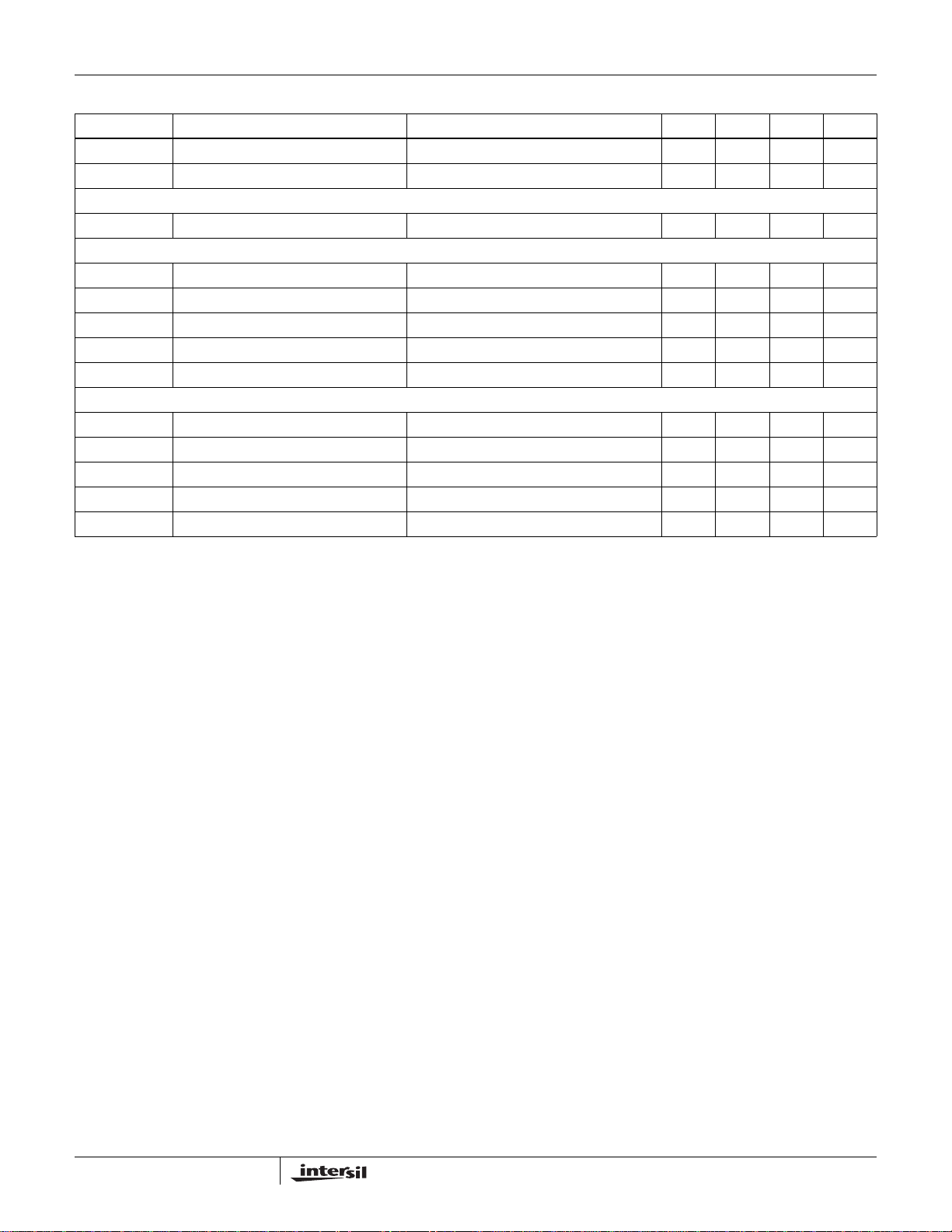
Short Circuit Load Resistance IL = 6A, prior to continuous application of
R
, OUTEN connected to OT
SHORT
100 mΩ
Current Limit 9A
Output Tempco -40°C < TA < 85°C ±1 %
Over-temperature Threshold 135 °C
Over-temperature Hysteresis 40 °C
Power Good Threshold Relative to
Programmed Output Voltage
VCC2SEL = 4V, V
= 3.50V ±6 ±10 ±14 %
OUT
Minimum VDD for Shutdown 3.15 V
Maximum VDD for Startup 4.15 V
Input Hysteresis V
HYS
= V
DDON
- V
DDOFF
0.5 V
Soft-start Slope 7V/ms
Maximum Duty Cycle 96 %
CONTROLLER - INPUTS
I
PUP
I
CSLOPE
VCC2DET, OUTEN Pull-up Current VCC2DET, OUTEN = 0 10 14 18 µA
C
Charging Current 23 28.5 34 µA
SLOPE
IFB1 FB1 Input Pull-up Current 2µA
R
OT
V
IH
V
IL
V
OH PWGD
V
OL PWGD
Over-temperature Pull-up Resistance OT = 0V 30 40 50 kΩ
VCC2DET, OUTEN Input High 4 V
VCC2DET, OUTEN Input Low 0.8 V
Powergood Drive High I
Powergood Drive Low I
= 1mA 3.5 V
LOAD
= -1mA 1.0 V
LOAD
CONTROLLER - REFERENCE
V
REF
Reference Accuracy I
= 0 1.247 1.260 1.273 V
REF
3
EL7556D
Electrical Specifications V
DD
= V
= 5V, C
IN
OSC
= 1nF, C
= 470pF, TA = 25°C, unless otherwise specified. (Continued)
SLOPE
PARAMETER DESCRIPTION CONDITIONS MIN TYP MAX UNIT
V
REFTC
V
REFLOAD
Reference Voltage Tempco 50 ppm/°C
Reference Load Regulation 0 < I
< 100µA 0.5 0.5 %/°C
LOAD
CONTROLLER - DOUBLER
VC2V Voltage Doubler Output V
DD
= 5V, I
= 10mA 7.5 8.1 8.7 V
LOAD
CONTROLLER - OSCILLATOR
F
RAMP
I
OSC CHG
I
OSC DIS
F
OSC
t
SYNC
Oscillator Ramp Amplitude 1.2 V
Oscillator Charge Current 0.2V < V
Oscillator Discharge Current 0.2V < V
< 1.4V 150 µA
OSC
< 1.4V 5 mA
OSC
Oscillator Initial Accuracy 105 125 145 kHz
Minimum Oscillator Sync Width 50 ns
POWER - FET
I
LEAK
R
DSON
R
DSONTC
t
BRM
t
LEB
LX Output Leakage to V
SS
LX = 0V 100 µA
Composite FET Resistance 18 30 mΩ
R
Tempco 0.1 mΩ/°C
DSON
FET Break Before Make Delay 10 ns
High Side FET Minimum on Time (LEB) 140 ns
4

Typical Performance Curves
EL7556D
Efficiency vs I
VDD=VIN=5.0V (±10%)
96
94
LOAD
(V
OUT
VDD=4.5V
=3.5V)
92
90
VDD=5V
88
VDD=5.5V
86
Efficiency (%)
84
82
TA=25°C
80
0.5 1.5 2.5 3.5 4.5 5.5
Line Regulation (C
3.54
TA=25°C
3.53
I
OUT
SLOPE
(A)
=100pF)
3.52
I
=0.5A
3.51
(V)
3.50
OUT
V
3.49
OUT
I
OUT
=3A
3.48
I
=6A
3.47
3.46
4.5 5.0 5.5
OUT
VIN (V)
6.5
Efficiency vs I
LOAD
(VDD=5.0V)
100
95
90
VCC=3.5V
VCC=2.5V
85
80
Efficiency (%)
VCC=1V
75
70
0.5
1.5
2.5 3.5 4.5 6.0
I
(A)
OUT
Load Regulation (C
3.54
TA=25°C
3.53
3.52
3.51
(V)
3.50
OUT
V
3.49
SLOPE
VIN=5V
=100pF)
VIN=5.5V
3.48
OUT
VIN=4.5V
(A)
3.47
3.46
0.5 3.0 6.0
I
5.5
Line Regulation vs C
VDD=VIN=5.0V ±10%
0.8
TA=25°C TA=25°C
0.7
SLOPE
(I
=3A)
OUT
0.6
0.5
V
(±) (%)
OUT
∆V
0.4
0.3
OUT
=3.5A
V
=2.5A
OUT
0.2
0.1
0.0
50 75
Line Regulation vs C
VIN=VDD=5.0V ±10%
0.8
TA=25°C TA=25°C
0.7
V
=1A
OUT
100 125 150 175
(pF)
C
SLOPE
SLOPE
0.6
0.5
I
(±) (%)
OUT
∆V
0.4
0.3
0.2
=6A VIN=4.5V
OUT
I
=0.5A
OUT
0.1
0.0
50 75
100 125 150 175
C
(pF)
SLOPE
Load Regulation vs C
I
=3A, +3A, -2.5A
OUT
0.6
SLOPE (VIN
=5.0V)
0.5
V
=3.5A
OUT
V
OUT
=1A
V
=2.5A
OUT
(±) (%)
OUT
∆V
0.4
0.3
0.2
0.1
0.0
50 75 100 125 150 175
Load Regulation vs C
I
=3A, +3A, -2.5A
OUT
0.8
C
SLOPE
(pF)
SLOPE
0.7
0.6
0.5
(±) (%)
0.4
OUT
0.3
∆V
0.2
VIN=5.5VVIN=5V
0.1
0.0
50 75
100 125 150 175
C
(pF)
SLOPE
5

Typical Performance Curves
EL7556D
V
vs C
OUT
SLOPE
(VIN=5.0V, I
1.5
TA=25°C TA=25°C
1.0
LOAD
=0.5A)
0.5
V
=1V
OUT
(±) (%)
OUT
∆V
0.0
-0.5
-1.0
-1.5
V
OUT
=3.5V
V
=2.5V
OUT
-2.0
-2.5
-3.0
50 75
F
OSC
10k
vs C
100 125 150 175
C
(pF)
SLOPE
OSC
TA=25°C
1k
(kHz)
100
OSC
F
10
V
OUT
Voltage [V
1.5
1.0
(%)
0.5
OUT
0.0
-0.5
Deviation in V
-1.0
Loop Gain Induced Error
-1.5
1.0 1.5
F
OSC
520
510
500
490
(kHz)
480
OSC
F
470
Variation vs Programmed Output
IDEAL
C
=(1+R3/R4)]
C
S
L
O
P
E
=
O
S
C
=
2
20
1
0
0
p
F
p
F
2.0 2.5 3.0 4.0
V
(V)
IDEAL
vs Temperature
VDD=4.5V
VDD=5.5V
VDD=5V
460
1
10
C
(pF)
OSC
100k100 1k
450
20
0
40 60 80 140
Temperature (°C)
100
3.5
120
I(VDD) + I(VIN) vs F
60
TA=25°C
OUTEN=V
50
OSC
DD
VDD=5.5V
I(VIN) vs F
16
14
TA=25°C
OUTEN=V
OSC
DD
12
(mA)
Q
I
40
30
VDD=4.5V
VDD=5V
20
(mA)
VIN
I
10
8
6
4
10
0
200 1000400 600 800 200 1000400 600 800
I(VDD) vs F
50
TA=25°C
45
OUTEN=V
40
35
OSC
DD
F
OSC
VDD=5.5V
Continuous ModeDiscontinuous Mode
(kHz)
30
25
(mA)
DD
I
20
15
VDD=4.5V
VDD=5V
2
Discontinuous Mode
0
I
DD
2.0
IN
1.5
(mA) + IV
DD
I
+ IVIN vs F
OSC
F
(kHz)
OSC
VDD=5.5V
VDD=4.5V
10
5
0
200 1000400 600 800
F
OSC
(kHz)
1.0
10
100 1000
F
(kHz)
OSC
VDD=5.5V
VDD=5V
VDD=4.5V
Continuous Mode
VDD=5V
6

Typical Performance Curves
EL7556D
Power On Reset
40
TA=25°C
OUTEN=V
DD
30
20
(mA)
Q
I
10
0
41
39
37
35
33
(°C/W)
JA
31
Θ
29
27
25
0.00 3.00
3.0
2.5
ΘJA vs Cu Area
F
=500k
OSC
3.5 4.5 5.0
4.0
V
(V)
DD
Board with no
Components
Board with
Inductor
Bare Cu Area (in2)
Minimum Output Voltage vs F
2.3
TJ=120°C
2.1
1.9
1.7
(V)
1.5
OUT
V
1.3
1.1
0.9
0.7
Maximum I
7556 Demo Board (31°C/W)
8.0
7.5
7.0
6.5
(A)
6.0
LOAD
I
5.5
5.0
4.5
OUTEN connected to OT
6.004.002.001.00 5.00
4.0
25 50
vs Temperature
LOAD
F
OSC
4535
(kHz)
TA (°C)
OSC
VDD=5.5V
VDD=4.5V
100 LFPM
Still Air
55
VDD=5V
70604030 65
R
vs Temperature
DSON
38
36
34
32
30
(mΩ)
28
DSON
R
26
24
22
20
0
Temperature (°C)
125755025 100
7

EL7556D
Pin Descriptions
I = Input, O = Output, S = Supply
PIN
NUMBER PIN NAME PIN TYPE FUNCTION
1 FB1 I Voltage feedback pin for the buck regulator. Active when VCC2DET is logic low. Normally connected to
external resistor divider between V
that FB1 is floating and VCC2DET is inadvertently connected to GND.
2 CREF I Bandgap reference bypass capacitor. Typically 0.1µF to V
3 CSLOPE I Slope compensation capacitor. Ramp width corresponds to LX duty cycle. C
normally 1:1.5.
4 COSC I Oscillator timing capacitor. F
Farads.
OSC
5 VDD S Power Supply for PWM control circuitry. Normally the same potential as V
6 VIN S Power supply for the buck regulator. Connected to the drain of the high-side NMOS FET.
7 VSSP S Ground return for the buck regulator. Connected to the source of the low-side synchronous NMOS FET.
8 VIN S Same as pin 6.
9 VSSP S Same as pin 7.
10 VSSP S Same as pin 7.
11 VSSP S Same as pin 7.
12 VSSP S Same as pin 7.
13 VCC2DET I VCC2DET interface logic input. When driven to logic 1 V
uses FB1 to determine V
OUT
: V
14 OUTEN I The switching regulator output is enabled when logic 1. The reference voltage output operates whenever
the power supply is qualified (V
15 OT O Over temperature indicator. Normally high. Pulls low when die temperature exceeds 135°C, returns to
the high state when die temperature has cooled to 100°C.
16 PWRGD O Power good window comparator output. Logic 1 when regulator output is within ±10% of programmed
voltage.
17 TEST I Test pin. Must be connected to VSSP in normal operation.
18 VSSP S Same as pin 7.
19 VSSP S Same as pin 7.
20 LX O Inductor drive pin. High current switching output whose average voltage equals the regulator output
voltage.
21 LX O Same as pin 20.
22 LX O Same as pin 20.
23 LX O Same as pin 20.
24 VHI I Gate drive to high-side driver. Bootstrapped from LX with a 0.1µF capacitor.
25 VSS S Ground return for the control circuitry.
26 C2V I Connected to voltage doubler output. Supplies gate drive to the low-side driver.
27 CP O Drives the negative side of charge pump capacitor at one-half the oscillator frequency F
28 FB2 I Voltage feedback pin. Active when VCC2DET is logic 1. Internally preset to V
and GND. A 2µA pull-up current forces V
OUT
.
SS
(Hz) can be approximated by: F
= 1.0V*(1+R3/R4).
OUT
>VPOR) regardless of the state of this pin.
DD
OUT
OSC
= 3.500V. When driven to logic 0 the PWM
OUT
SLOPE
(Hz) = 0.0001/C
.
IN
= 3.5V.
OUT
to VSS in the event
to C
OSC
OSC
OSC
ratio is
. C
OSC
.
in
8

Block Diagram
EL7556D
FB1, Pin 1
FB2, Pin 28
VCCDET, Pin 13
CSLOPE, Pin 3
CREF, Pin 27
OUTEN, Pin 14
COSC, Pin 4
VDD
1.26V
PWRGD, Pin 16
CP, Pin 27
C2V, Pin 26
VHI, Pin 24
VDD and VIN,
Pin 5,6,8
LX, Pin 20-23
VSSP, Pin 912, 18-19
OT, Pin 15
V
Pin 25
SS,
S
-
+
-
+
-
+
Current Sense
-
+
Current Limit
-
+
PWM
VDD
R
SS
C
SS
V2X
-
+
LEB T
DELAY
Q
R
Q
S
FF
R
S
Zero Cross Detect
Over Temp
Sensor
+
-
2-1 MUX
4V
UVLO
-
S
+
-
R
+
Applications Information
Circuit Description
General
The EL7556D is a fixed frequency, current mode controlled
DC:DC converter with integrated N-channel power
MOSFETS and a high precision reference. The device
incorporates all of the active circuitry required to implement a
cost effective, user-programmable 6A synchronous buck
converter suitable for use in CPU power supplies. By
combining fused-lead packaging technology with an efficient
synchronous switching architecture, high power outputs
(21W) can be realized without the use of discrete external
heat sinks.
Theory of Operation
The EL7556D is composed of 7 major blocks:
1. PWM Controller
2. Output Voltage Mode Select
3. NMOS Power FETS and Drive Circuitry
4. Bandgap Reference
5. Oscillator
6. Temperature Sensor
7. Power Good and Power On Reset
PWM Controller
The EL7556D regulates output voltage through the use of
current-mode controlled pulse width modulation. The three
main elements in a PWM controller are the feedback loop
and reference, a pulse width modulator whose duty cycle is
controlled by the feedback error signal, and a filter which
averages the logic level modulator output. In a step-down
(buck) converter, the feedback loop forces the timeaveraged output of the modulator to equal the desired output
voltage. Unlike pure voltage-mode control systems currentmode control utilizes dual feedback loops to provide both
output voltage and inductor current information to the
controller. The voltage loop minimizes DC and transient
errors in the output voltage by adjusting the PWM duty-cycle
in response to changes in line or load conditions. Since the
output voltage is equal to the time-average of the modulator
output the relatively large LC time constants found in power
supply applications generally results in low bandwidth and
poor transient response. By directly monitoring changes in
inductor current via a series sense resistor the controller’s
response time is not entirely limited by the output LC filter
and can react more quickly to changes in line or load
conditions. This feed-forward characteristic also simplifies
AC loop compensation since it adds a zero to the overall
loop response. Through proper selection of the currentfeedback to voltage-feedback ratio, the overall loop
response will approach a one pole system. The resulting
system offers several advantages over traditional voltage
9

EL7556D
control systems, including simpler loop compensation, pulse
by pulse current limiting, rapid response to line variation and
good load step response.
The heart of the controller is a triple-input direct summing
comparator which sums voltage feedback, current feedback
and slope compensating ramp signals together. Slope
compensation is required to prevent system instability which
occurs in current-mode topologies operating at duty-cycles
greater than 50% and is also used to define the open-loop
gain of the overall system. The compensation ramp
amplitude is user adjustable and is set using a single
external capacitor (C
). Each comparator input is
SLOPE
weighted and determines the load and line regulation
characteristics of the system. Current feedback is measured
by sensing the inductor current flowing through the high-side
switch whenever it is conducting. At the beginning of each
oscillator period the high-side NMOS switch is turned on and
C
ramps positively from its reset state (V
SLOPE
REF
potential). The comparator inputs are gated off for a
minimum period of time (LEB) after the high-side switch is
turned on to allow the system to settle. The Leading Edge
Blanking (LEB) period prevents the detection of erroneous
voltages at the comparator inputs due to switching noise.
When programming low regulator output voltages the LEB
delay will limit the maximum operating frequency of the
circuit since the LEB will result in a minimum duty-cycle
regardless of the PWM error voltage. This relationship is
shown in the performance curves. If the inductor current
exceeds the maximum current limit (I
), a secondary
LMAX
over-current comparator will terminate the high-side switch.
If I
is then compared to the reference voltage V
has not been reached, the regulator output voltage
LMAX
REF
. The
resultant error voltage is summed with the current feedback
and slope compensation ramp. The high-side switch
remains on until all three comparator inputs have summed to
zero, at which time the high-side switch is turned off and the
low-side switch is turned on. In order to eliminate crossconduction of the high-side and low-side switches a 10ns
break-before-make delay is incorporated in the switch driver
circuitry. In the continuous mode of operation the low-side
switch will remain on until the end of the oscillator period. In
order to improve the low current efficiency of the EL7556D, a
zero-crossing comparator senses when the inductor
transitions through zero. Turning off the low-side switch at
zero inductor current prevents forward conduction through
the internal clamping diodes (LX to V
) when the low-side
SSP
switch turns off, reducing power dissipation. The output
enable (OUTEN) input allows the regulator output to be
disabled by an external logic control signal.
Output Voltage Mode Select
The VCC2DET multiplexes the FB1 and FB2 pins to the
PWM controller. A logic 1 on VCC2DET selects the FB2
input and forces the output voltage to the internally
programmed value of 3.50V. A logic zero on VCC2DET
selects FB1 and allows the output to be programmed from
1.0 to 3.8V. In general:
R
V
OUT
1V 1
× Volt×=
3
-------+
R
4
However, due to the relatively low open loop gain of the
system, gain errors will occur as the output voltage and loopgain are changed. This is shown in the performance curves.
(The output voltage is factory trimmed to minimize error at a
2.50V output). A 2uA pull-up current from FB1 to V
V
to GND in the event that FB1 is not used and the
OUT
forces
IN
VCC2DET is inadvertently toggled between the internal and
external feedback mode of operation.
NMOS Power FETs and Drive Circuitry
The EL7556D integrates low resistance (25mΩ) NMOS
FETS to achieve high efficiency at 6A. Gate drive for both
the high-side and low-side switches is derived through a
charge pump consisting of the CP pin and external
components D1-D3 and C5-C6. The CP output is a low
resistance inverter driven at one-half the oscillator
frequency. This is used in conjunction with D2-D3 to
generate a 7.5V (typical) voltage on the C2V pin which
provides gate drive to the low-side NMOS switch and
associated level shifter. In order to use an NMOS switch for
the high-side drive it is necessary to drive the gate voltage
above the source voltage (LX). This is accomplished by
boot-strapping the V
pin above the C2V voltage with
HI
capacitor C6 and diode D1. When the low-side switch is
turned on the LX voltage is close to GND potential and
capacitor C6 is charged through diodes D1-D3 to
approximately 6.9V. At the beginning of the next cycle the
high side switch turns on and the LX pin begins to rise from
GND to V
potential. As the LX pin rises the positive plate
DD
of capacitor C6 follows and eventually reaches a value of
approximately 11.2V, for V
=5V. This voltage is then level
DD
shifted and used to drive the gate of the high-side FET, via
the V
pin.
HI
Reference
A 1% temperature compensated band gap reference is
integrated in the EL7556D. The external C
REF
capacitor
acts as the dominant pole of the amplifier and can be
increased in size to maximize transient noise rejection. A
value of 0.1uF is recommended.
Oscillator
The system clock is generated by an internal relaxation
oscillator with a maximum duty-cycle of approximately 96%.
Operating frequency can be adjusted through the C
or can be driven by an external clock source. If the oscillator
is driven by an external source, care must be taken in the
selection of C
SLOPE
. Since the C
OSC
and C
SLOPE
determine the open loop gain of the system, changes to
C
require corresponding changes to C
OSC
SLOPE
pin
OSC
values
in order to
10

EL7556D
maintain a constant gain ratio. The recommended ratio of
C
OSC
to C
SLOPE
is 1.5:1
Temperature Sensor
An internal temperature sensor continuously monitors die
temperature. In the event that die temperature exceeds the
thermal trip-point, the OT pin will output a logic 0. The upper
and lower trip points are set to 135°C and 100°C,
respectively. To enable thermal shutdown this pin should be
tied directly to OUTEN. Use of this feature is recommended
during normal operation
Power Good and Power On Reset
During power up the output regulator will be disabled until
V
reaches a value of approximately 4.0V. Approximately
IN
500mV of hysteresis is present to eliminate noise induced
oscillations.
Under-voltage and over-voltage conditions on the regulator
output are detected through an internal window comparator.
A logic 1 on the PWRGD output indicates that regulated
output voltage is within ±10% of the nominally programmed
output voltage. Although small, the typical values of the
PWRGD threshold will vary with changes to external
feedback (and resultant loop gain) of the system. This
dependence is shown in the typical performance curves.
Additional information can be found in Application Note #8
(Measuring the Thermal Resistance of Power SurfaceMount Packages).
If the thermal shutdown pin is connected to OUTEN the IC
will enter thermal shutdown when the maximum junction
temperature is reached. For a thermal shutdown of 135ºC
and power dissipation of 2.2W the ambient temperature is
limited to a maximum value of 67ºC (typical). The ambient
temperature range can be extended with the application of
air flow. For example, the addition of 100LFM reduces the
thermal resistance by approximately 15% and can extend
the operating ambient to 77ºC (typical). Since the thermal
performance of the IC is heavily dependent on the board
layout, the system designer should exercise care during the
design phase to ensure that the IC will operate under the
worst-case environmental conditions.
Thermal Management
The EL7556D utilizes “fused lead” packaging technology in
conjunction with the system board layout to achieve a lower
thermal resistance than typically found in standard 28-pin
SO packages. By fusing (or connecting) multiple external
leads to the die substrate within the package, a very
conductive heat path to the outside of the package is
created. This conductive heat path MUST then be connected
to a heat sinking area on the PCB in order to dissipate heat
out and away from the device. The conductive paths for the
EL7556D package are the fused leads: # 7, 9, 10, 11, 12, 18,
and 19. If a sufficient amount of PCB metal area is
connected to the fused package leads, a junction-to-ambient
thermal resistance of approximately 31°C/W can be
achieved (compared to 78°C/W for a standard SO28
package). The general relationship between PCB heatsinking metal area and the thermal resistance for this
package is shown in the Performance Curves section of this
data sheet. It can be readily seen that the thermal resistance
for this package approaches an asymptotic value of
approximately 31°C/W without any airflow.
All Intersil U.S. products are manufactured, assembled and tested utilizing ISO9000 quality systems.
Intersil Corporation’s quality certifications can be viewed at www.intersil.com/design/quality
Intersil products are sold by description only. Intersil Corporation reserves the right to make changes in circuit design, software and/or specifications at any time without
notice. Accordingly, the reader is cautioned to verify that data sheets are current before placing orders. Information furnished by Intersil is believed to be accurate and
reliable. However, no responsibility is assumed by Intersil or its subsidiaries for its use; nor for any infringements of patents or other rights of third parties which may result
from its use. No license is granted by implication or otherwise under any patent or patent rights of Intersil or its subsidiaries.
For information regarding Intersil Corporation and its products, see www.intersil.com
11
 Loading...