

®
EL7554
Data Sheet November 5, 2007
Monolithic 4A DC/DC Step-Down
Regulator
The EL7554 is a full-feature synchronous 4A step-down
regulator capable of up to 96% efficiency. This device
operates from 3V to 6V V
input supply. With internal CMOS
IN
power FETs, the device can operate at up to 100% duty ratio,
allowing for output voltage range from 0.8V up to nearly
V
.The adjustable high switching frequency of up to 1MHz
IN
enables the use of small components, making the whole
converter occupy less than 0.58 square inch with components
on one side of the PCB. The EL7554 operates at constant
frequency PWM mode, making external synchronization
possible. The EL7554 features soft-start and full start-up
control, which eliminates the in-rush current and enables
users to control the start-up of multiple converters to any
configuration with ease. The EL7554 also offers a ±5%
voltage margining capability that allows ra ising and lowering
of the supplies derived from the EL7554 to validate the
performance and reliability of system cards quickly and easily
during manufacturing testing. A junction temperature indicator
conveniently monitors the silicon die temperature, saving
designers time in the tedious thermal characterization.
An easy-to-use simulation tool is available for download and
can be used to modify design parameters such as switching
frequency, voltage ripple, ambient temperature, as well as
view schematics waveforms, efficiency graphs, and
complete BOM with Gerber layout.
The EL7554 is available in a 28 Ld HTSSOP package and is
specified for operation over the -40°C to +85°C temperature
range.
Ordering Information
TEMP.
PART
NUMBER
EL7554IRE* 7554IRE -40 to +85 28 Ld HTSSOP MDP0048
EL7554IREZ*
(See Note)
*Add “-T7” or “-T13” suffix for tape and reel. Please refer to TB347 for
details on reel specifications.
NOTE: These Intersil Pb-free plastic packaged products employ
special Pb-free material sets; molding compounds/die attach
materials and 100% matte tin plate PLUS ANNEAL - e3 termination
finish, which is RoHS compliant and compatible with both SnPb and
Pb-free soldering operations. Intersil Pb-free products are MSL
classified at Pb-free peak reflow temperatures that meet or exceed
the Pb-free requirements of IPC/JEDEC J STD-020.
PART
MARKING
7554IREZ -40 to +85 28 Ld HTSSOP
RANGE
(°C) PACKAGE
(Pb-free)
PKG.
DWG. #
MDP0048
FN7360.5
Features
• Integrated MOSFETs
• 4A continuous output current
• Up to 96% efficiency
• All ceramic capacitors
• Multiple supply start-up tracking
• Built-in ±5% voltage margining
• 3V to 6V input voltage
2
• 0.58 in
footprint with components on one side of PCB
• Adjustable switching frequency to 1MHz
• Oscillator synchronization possible
• 100% duty ratio
• Junction temperature indicator
• Over-temperature protection
• Internal soft-start
• Variable output voltage down to 0.8V
• Power-good indicator
• 28 Ld HTSSOP package
• Pb-free available (RoHS compliant)
Applications
• Point-of-regulation power sup pli es
• FPGA Core and I/O supplies
• DSP, CPU Core, and IO supplies
• Logic/Bus supplies
• Portable equipment
Related Documentation
• Technical Brief 418 - Using the EL7554 Demo Board
• Easy to use applications software simulation tool available
at www.intersil.com/dc-dc
1
CAUTION: These devices are sensitive to electrostatic discharge; follow proper IC Handling Procedures.
1-888-INTERSIL or 1-888-468-3774
| Intersil (and design) is a registered trademark of Intersil Americas Inc.
All other trademarks mentioned are the property of their respective owners.
Copyright Intersil Americas Inc. 2004-2007. All Rights Reserved
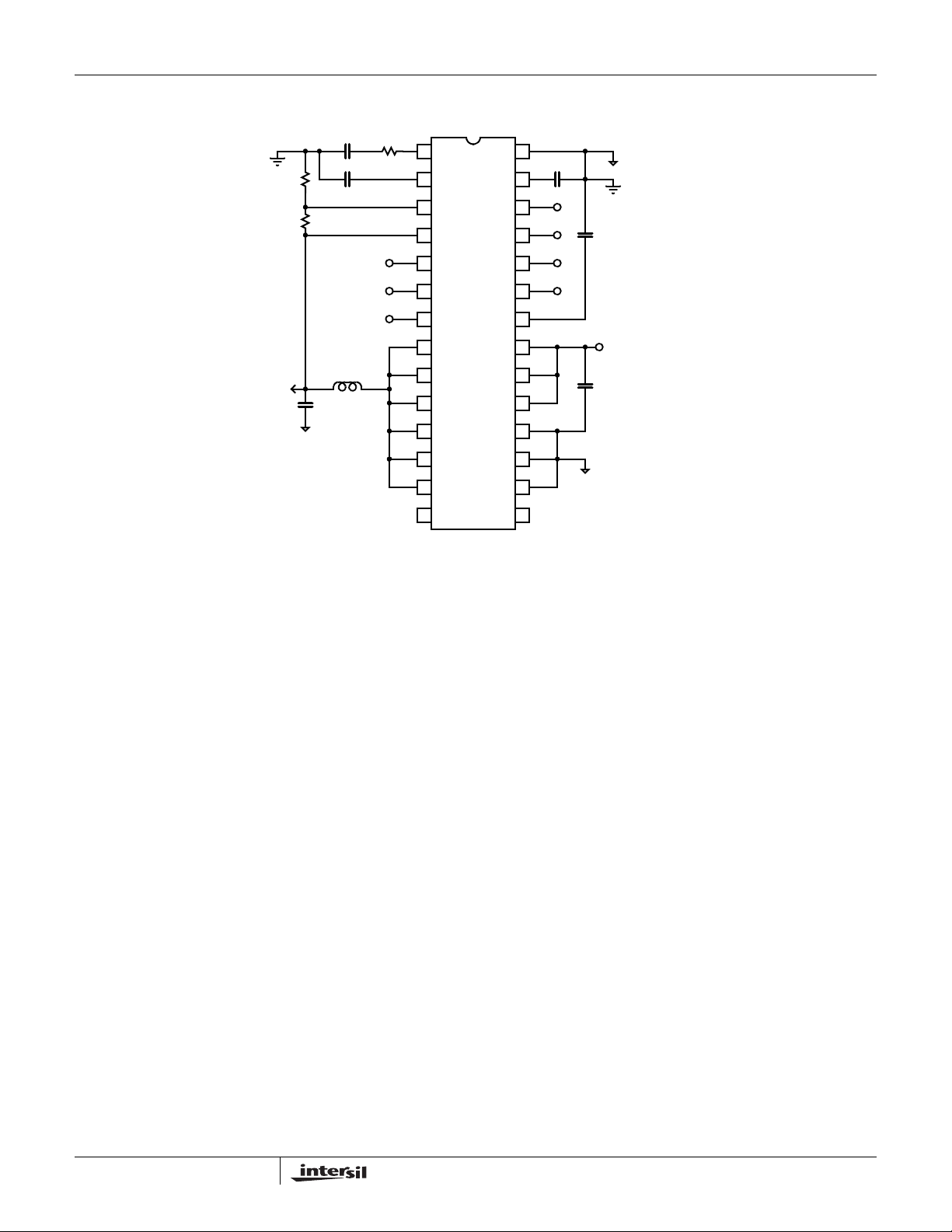
Typical Application Diagram
R
2
10.2K
R
1
12.7K
C
C
0.018µF
0.018µF
R
C
2.32K
EL7554
1
COMP
2
VREF
3
FB
4
VO
5
VTJ
SGND
COSC
STN
STP
EN
28
220pF
27
C
OSC
26
25
24
0.22µF
V
OUT
(1.8V, 4A)
47µF
C
2.2µH
OUT
6
TM
7
SEL
8 21
LX
9
LX
10
LX
11
LX
12
LX
LX
13
NC
14 15
PG
VDD
VIN
VIN
VIN
PGND
PGND
PGND
NC
23
22
V
IN
(3V TO
20
19
C
18
17
16
6V)
2x10µF
IN
2
FN7360.5
November 5, 2007
EL7554
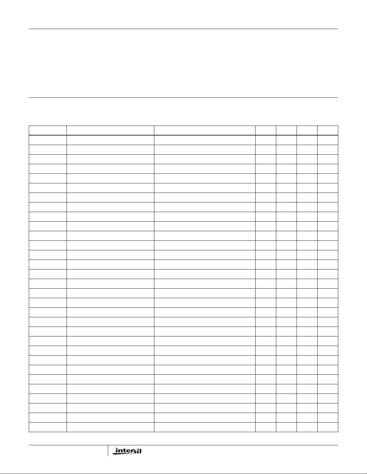
Absolute Maximum Ratings (T
V
, VDD to SGND. . . . . . . . . . . . . . . . . . . . . . . . . . . -0.3V to +6.5V
IN
VX to PGND. . . . . . . . . . . . . . . . . . . . . . . . . . . . . -0.3V to V
SGND to PGND. . . . . . . . . . . . . . . . . . . . . . . . . . . . . -0.3V to +0.3V
COMP, V
SEL, PG, EN, STP, STN, C
CAUTION: Do not operate at or near the maximum ratings listed for extended periods of time. Exposure to such conditions may adversely impact product reliability and
result in failures not covered by warranty.
IMPORTANT NOTE: All parameters having Min/Max specifications are guaranteed. T yp values are for information purposes only. Unless otherwise noted, all tests are
at the specified temperature and are pulsed tests, therefore: T
, FB, VO, VTJ, TM,
REF
to SGND . . . . . -0.3V to VDD +0.3V
OSC
DC Electrical Specifications V
= +25°C)
A
= V
DD
+0.3V
IN
= TC = T
J
= 3.3V, TA = TJ = +25°C, C
IN
A
Storage Temperature. . . . . . . . . . . . . . . . . . . . . . . .-65°C to +150°C
Junction Temperature . . . . . . . . . . . . . . . . . . . . . . . . . . . . . . +125°C
Ambient Operating Temperature . . . . . . . . . . . . . . . .-40°C to +85°C
Pb-free reflow profile . . . . . . . . . . . . . . . . . . . . . . . . . .see link below
http://www.intersil.com/pbfree/Pb-FreeReflow.asp
= 390pF, Unless Otherwise Specified
OSC
PARAMETER DESCRIPTION CONDITIONS MIN TYP MAX UNIT
V
IN
V
REF
V
REFTC
V
REFLOAD
V
RAMP
I
OSC_CHG
I
OSC_DIS
I
VDD
I
VDD_OFF
V
DD_OFF
V
DD_ON
T
OT
T
HYS
I
LEAK
I
LMAX
R
DSON1
R
DSONTC2
R
DSONTC
I
STP
I
STN
V
PGP
V
PGN
V
PG_HI
V
PG_LO
V
OVP
V
FB
V
FB_LINE
GM
EA
V
FB_TC
F
S
I
FB
Input Voltage Range 3 6 V
Reference Accuracy 1.24 1.26 1.28 V
Reference Temperature Coefficient 50 ppm/°C
Reference Load Regulation 0 < I
< 50µA -1 %
REF
Oscillator Ramp Amplitude 1.15 V
Oscillator Charge Current 0.1V < V
Oscillator Discharge Current 0.1V < V
< 1.25V 200 µA
OSC
< 1.25V 8 mA
OSC
VDD Supply Current VEN = 1 (L disconnected) 2 2.7 5 mA
V
Standby Current EN = 0 1 1.5 mA
DD
VDD for Shutdown 2.4 2.65 V
VDD for Startup 2.6 2.95 V
Over-temperature Threshold 135 °C
Over-temperature Hysteresis 20 °C
Internal FET Leakage Current EN = 0, LX = 6V (low FET), LX = 0V (high FET) 10 µA
Peak Current Limit 6A
PFET On Resistance 35 70 mΩ
NFET On Resistance 30 60 mΩ
R
Tempco 0.2 mΩ/°C
DSON
STP Pin Input Pull-down Current V
STN Pin Input Pull-up Current V
= VIN/2 -4 2.5 µA
STP
= VIN/2 2.5 4 µA
STN
Positive Power Good Threshold With respect to target output voltage 6 14 %
Negative Power Good Threshold With respect to target output voltage -14 -6 %
Power Good Drive High I
= 1mA 2.6 V
PG
Power Good Drive Low IPG = -1mA 0.5 V
Output Over-voltage Protection 10 %
Output Initial Accuracy I
Output Line Regulation V
= 0A 0.79 0.8 0.81 V
LOAD
= 3.3V, ΔVIN = 10%, I
IN
= 0A 0.2 0.5 %
LOAD
Error Amplifier Transconductance VCC = 0.65V 85 125 165 µs
Output Temperature Stability 0°C < TA < +85°C, I
= 3A ±1 %
LOAD
Switching Frequency 300 370 440 kHz
Feedback Input Pull-up Current V
= 0V 100 200 nA
FB
3
FN7360.5
November 5, 2007
EL7554
DC Electrical Specifications V
DD
= V
= 3.3V, TA = TJ = +25°C, C
IN
= 390pF, Unless Otherwise Specified
OSC
PARAMETER DESCRIPTION CONDITIONS MIN TYP MAX UNIT
V
EN_HI
V
EN_LO
I
EN
TM, S
TM, S
EL_HI
EL_LO
EN Input High Level 2.6 V
EN Input Low Level 1V
Enable Pull-up Current VEN = 0 -4 -2.5 µA
Input High Level 2.6 V
Input Low Level 1V
Pin Descriptions
PIN NUMBER PIN NAME PIN FUNCTION
1 COMP Error amplifier output; place loop compensation components here
2 VREF B andgap reference bypass capacitor; typically 0.01µF to 0.047µF to SGND
3 FB Voltage feedback input; connected to external resistor divider between V
output; also used for speed-up capacitor connection
4 VO Output sense for fixed output; also used for speed-up capacitor connection
5 VTJ Junction temperature monitor output, connected to a 0.01µF - 0.047µF to SGND
6 TM Stress test enable; allows ±5% output movement; needs a pull-down resistor (1k - 100k); connect to
SGND if function is not used
7 SEL Positive or negative voltage margining set pin; needs a pull-down resistor (1k - 100k); connect to SGND
if function is not used
8, 9, 10, 11, 12, 13 LX Inductor drive pin; high current output whose average voltage equals the regulator output voltage
14, 15 NC Not used
16, 17, 18 PGND Ground return of the regulator; connected to the source of the low-side synchronous NMOS Power FET
19, 20, 21 VIN Power supply input of the regulator; connected to the drain of the high-side PMOS Power FET
22 VDD Control circuit positive supply; connected to V
through an internal 20Ω resistor
IN
23 PG Power-good window comparator output; logic 1 when regulator output is within ±10% of target output
voltage
24 EN Chip enable, active high; a 2µA internal pull-up current enables the device if the pin is left open; a
capacitor can be added at this pin to delay the start of a converter
25 STP Auxilliary supply tracking positive input; tied to regulator output to synchronize start-up with a second
supply; leave open for standalone operation; 2µA internal pull-up current
26 STN Auxiliary supply tracking negative input; connect to output of a second supply to synchronize start-up;
leave open for standalone operation; 2µA internal pull-up current
27 COSC Oscillator timing capacitor (see performance curves)
28 SGND Control circuit negative supply or signal ground
and SGND for adjustable
OUT
4
FN7360.5
November 5, 2007

5

Typical Performance Curves
VIN = VD = 3.3V, VO = 1.8V, IO = 4A, L = 2.2µH, CIN = 2x10µF, C
EL7554
= 47µF, C
OUT
= 220pF, TA = +25°C unless otherwise noted.
OSC
1
0.95
0.9
0.85
0.8
0.75
EFFICIENCY (%)
0.7
0.65
0.6
01 4
VO=0.8V
FIGURE 1. EFFICIENCY (V
1.266
1.264
1.262
1.26
1.258
1.256
REF
V
1.254
1.252
1.25
1.248
1.246
-50 150
VDD=3.3V
0
JUNCTION TEMPERATURE
VO=3.3V
VO=1V
VO=1.2V
23
IO (A)
IN
VDD=5V
50
VO=1.8V
= 5V)
100
VO=2.5V
100
95
90
85
80
75
EFFICIENCY (%)
70
65
60
VO=0.8V
VO=1V
01 4
FIGURE 2. EFFICIENCY (V
1.6
1.5
1.4
1.3
TJ
V
1.2
1.1
1
0.9
-50 150
VDD=3.3V
VDD=5V
JUNCTION TEMPERATURE
VO=2.5V
VO=1.2V
VO=1.8V
23
IO (A)
= 3.3V)
IN
500
100
FIGURE 3. V
4
3.5
3
2.5
2
1.5
1
3456
3.5 4.5 5.5
FIGURE 5. V
vs TEMPERATURE
REF
V
EN_HI
V
EN_LOW
V
(V)
DD
& V
EN_HI
EN_LOW
vs V
DD
6
FIGURE 4. V
1200
1000
800
600
(kHz)
S
F
VDD=3.3V
500
200
0
200 400 600
100 300 500 700
FIGURE 6. FS vs C
vs TEMPERATURE
TJ
VDD=5V
C
(pF)
OSC
OSC
FN7360.5
November 5, 2007

Typical Performance Curves (Continued)
= VD = 3.3V, VO = 1.8V, IO = 4A, L = 2.2µH, CIN = 2x10µF, C
V
IN
EL7554
= 47µF, C
OUT
= 220pF, TA = +25°C unless otherwise noted.
OSC
610
605
600
(KHz)
S
F
595
590
585
01.52.54
0.5 2 3.5
50
45
40
(°C/W)
JA
35
θ
30
VIN=5V
VIN=3.3V
1
IO (A)
FIGURE 7. FS vs I
CONDITION:
28 Ld HTSSOP THERMAL PAD
SOLDERED TO 2-LAYER PCB
WITH 0.039" THICKNESS AND
1 OZ. COPPER ON BOTH SIDES
O
3
0.8
0.6
0.4
0.2
(%)
0.0
-0.2
-0.4
04
123
IO (A)
FIGURE 8. LOAD REGULATIONS
JEDEC JESD51-7 HIGH EFFECTIVE THERMAL
CONDUCTIVITY TEST BOARD
3.5
3.0
2.5
2.0
1.5
1.0
0.5
H
T
S
θ
S
J
O
A
=
P
3
2
0
8
°
C
/
W
25
123456789
PCB AREA (in
2
)
FIGURE 9. HTSSOP THERMAL RESISTANCE vs PCB AREA
(NO AIR FLOW)
JEDEC JESD51-3 LOW EFFECTIVE THERMAL
CONDUCTIVITY TEST BOARD
1.00
0.90
0.80
0.70
0.60
0.50
0.40
0.30
0.20
0.10
0
ALLOWABLE POWER DISSIPATION (W)
0 255075100 150
θ
J
AMBIENT TEMPERATURE (°C)
FIGURE 11. PACKAGE POWER DISSIPATION vs AMBIENT TEMPERATURE
ALLOWABLE POWER DISSIPATION (W)
0
0 25 50 75 100 150
AMBIENT TEMPERATURE (°C)
12585
FIGURE 10. PACKAGE POWER DISSIP A TION vs AMBIENT
TEMPERATURE
H
T
S
S
A
O
=
P
1
1
2
0
8
°
C
/
W
85
125
7
FN7360.5
November 5, 2007

Waveforms
VIN = VD = 3.3V, VO = 1.8V, IO = 4A, L = 2.2µH, CIN = 2x10µF, C
VIN (2V/DIV)
I
(1A/DIV)
IN
(1V/DIV)
V
O
EL7554
= 47µF, C
OUT
= 220pF, TA = +25°C unless otherwise noted.
OSC
ΔVIN (100mV/DIV)
V
(2V/DIV)
LX
0.5ms/DIV
FIGURE 12. START-UP
50µs/DIV
PG (2V/DIV)
V
EN
IIN (2A/DIV)
(2V/DIV)
V
O
1µs/DIV
FIGURE 13. STEADY-STATE OPERATION
100µs/DIV
ΔV
3A
1.0A
I
ΔVO (100mV/DIV)
FIGURE 14. SHUT-DOWN FIGURE 15. TRANSIENT RESPONSE
(10mV/DIV)
O
O
1ms/DIV
FIGURE 16. VOLTAGE MARGINING
8
TM
SEL
(200mV/DIV)
ΔV
O
PG
(2V/DIV)
V
O
V
LX
0.5ms/DIV
FIGURE 17. OVER-VOLTAGE SHUT-DOWN
November 5, 2007
(5V/DIV)
FN7360.5

Waveforms (Continued)
= VD = 3.3V, VO = 1.8V, IO = 4A, L = 2.2µH, CIN = 2x10µF, C
V
IN
VIN (2V/DIV)
(2A/DIV)
I
IN
EL7554
= 47µF, C
OUT
= 220pF, TA = +25°C unless otherwise noted.
OSC
VIN (5V/DIV)
(1V/DIV)
V
O
CIN = 100µF,
= 150µF
C
OUT
2ms/DIV
FIGURE 18. ADJUSTABLE START-UP
Detailed Description
The EL7554 is a full-feature synchronous 6A step-down
regulator capable of up to 96% efficiency. This device
operates from 3V to 6V V
CMOS power FETs, the device can operate at up to 100%
duty ratio, allowing for output voltage range from 0.8V up to
nearly V
.The adjustable high switching frequency of up to
IN
1MHz enables the use of small components, making the
whole converter occupy less than 0.58 square inch with
components on one side of the PCB. The EL7554 operates
at constant frequency PWM mode, making external
synchronization possible. Patented on-chip resistorless
current-sensing enables current mode control, which
provides over-current protection, and excellent step load
response. The EL7554 features soft-start and full start-up
control, which eliminate the in-rush current and enables
users to control the start-up of multiple converters to any
configuration with ease. The EL7554 also offers a ±5%
voltage margining capability that allows raising and lowering
of the supplies derived from the EL7554 to validate the
performance and reliability of system cards quickly and
easily during manufacturing testing. A junction temperature
indicator conveniently monitors the silicon die temperature,
saving designers time in the tedious thermal
characterization.
Start-Up
The EL7554 employs a special soft-start to suppress the inrush current (see Figure 12). The start-up process takes
about 2ms and begins when the input voltage reaches about
2.8V and EN pin voltage 2V. When EN is released from
LOW, or the converter comes out of thermal shut-down
mode, the soft-start process repeats. When the input voltage
ramps up too slowly, slight over- current at the input can
input supply. With internal
IN
VO1=2.5V
=1.8V
V
O2
CIN = 100µF,
C
= 150µF
OUT
5ms/DIV
FIGURE 19. TRACKING START-UP
occur. Connecting a small capacitor at EN will delay the
start-up. The delay time T
V
EN_HI
EN
--------------------
×=
I
EN
TDC
can be calculated by:
D
where:
•C
is the capacitance at EN pin
EN
•V
is the EN input high level (function of VDD voltage,
EN_HI
see Figure 5)
is the EN pin pull-up current, nominal 2.5µA
•I
EN
If a slower than 2ms soft start-up is needed, please refer to
Full Start-Up Control section.
Steady-State Operation
The converter always operates at fixed frequency
continuous-conduction mode. For fast transient response,
peak current control method is employed. The inductor
current is sensed from the upper PFET. This current signal,
the slope compensation, and the compensated error signal
are fed to the PWM comparator to generate the PWM signal
for the internal power switches. When the upper PFET is on,
the low-side NFET is off and input voltage charges the
inductor. When PFET is off, the NFET is on and energy
stored in the inductor is dumped to the output to maintain
constant output voltage. Therefore, the LX waveform is
always a stable square waveform (see Figure 13) with peak
close to V
. So LX is a good indication that the converter is
IN
operating properly.
100% Duty Ratio
EL7554 uses CMOS as internal synchronous power
switches. The upper switch is a PMOS and the lower switch
an NMOS. This not only saves a boot capacitor, it also
allows 100% turn-on of the upper PFET switch, achieving
9
FN7360.5
November 5, 2007

VO close to VIN. The maximum achievable VO is:
VOVINRLR
Where R
+()IO×–=
DSON1
is the DC resistance on the inductor and R
L
DSON1
is the PFET on-resistance, nominal 35mΩ at room
temperature with tempco of 0.2mΩ/°C.
Output Voltage Selection
The output voltage can be as high as the input voltage minus
the PMOS and inductor voltage drops. Use R
and R2 to set
1
the output voltage according to the following formula:
R
⎛⎞
1
V
0.8 1
O
Standard values of R
VO (V) R1 (kΩ)R
-------
+
×=
⎜⎟
R
⎝⎠
2
and R2 are listed in Table 1.
1
TABLE 1.
(kΩ)
2
0.8 2 Open
12.4910
1.2 4.99 10
1.5 10 11.5
1.8 12.7 10.2
2.5 21.5 10
3.3 36 11.5
Voltage Margining
The EL7554 has built-in 5% load stress test (commonly
called voltage margining) function. Combinations of TM and
SEL set the margins shown in Table 2. When this function is
not used, both pins should be connected to SGND, either
directly or through a 10kΩ resister. Figure 16 shows this
feature.
TABLE 2.
CONDITION TM SEL V
Normal 0 X Nominal
High Margin 1 1 Nominal + 5%
Low Margin 1 0 Nominal - 5%
O
Switching Frequency
The regulator operates from 200kHz to 1MHz. The switching
frequency is generated by a relaxation comparator and
adjusted by a C
ratio and runs from 0.2V to 1.2V. Please refer to Figure 6 for
a specific frequency.
When external synchronization is required, use the following
circuit for connection. Always choose the converter selfswitching frequency 20% lower than the sync frequency to
accommodate component variations.
. The triangle waveform has 95% duty
OSC
EL7554
100pF
EL7554
C
OSC
FIGURE 20. EXTERNAL SYNC CIRCUIT
EXTERNAL SYNC
SOURCE
Thermal Protection and Junction Temperature
Indicator
An internal temperature sensor continuously monitors the
junction temperature. In the event that the junction
temperature exceeds +135°C, the regulator is in a fault
condition and will shut down. When the temperature falls
back below +110°C, the regulator goes through the soft-start
procedure again.
The V
junction temperature T
pin is an accurate indicator of the internal silicon
TJ
, which can be determined by the
J
following formula. This saves engineering time.
–
1.2 V
TJ
TJ75
------------------------
+=
0.00384
where VTJ is the voltage at VTJ pin.
Under-Voltage Lockout (UVLO)
When VDD falls bellow 2.5V, the regulator shuts down. When
V
rises above 2.8V, converter goes through soft-start
DD
process again.
Power Good Indicator (PG) and Over-Voltage
Protection
When the output reaches 10% of the preset voltage, the PG
pin outputs a HI signal as shown in the start-up waveform
(Figure 12). If the output voltage is higher than 10% of the
preset value for any reason, PG will go low and the regulator
will shut down. In addition to the indication power is good,
the PG pin can be used for multiple regulators’ start-up
control as described in the next section.
Full Start-Up Control
The EL7554 offers full start-up control. The core of this
control is a start-up comparator in front of the main PWM
controller. The STP and STN are the inputs to the
comparator, whose HI output forces the PWM comparator to
skip switching cycles. The user can choose any of the
following control configurations:
1. ADJUSTABLE SOFT-START
In this configuration, the ramp-up time is adjustable to any
time longer than the building soft-start time of 2ms. The
approximate ramp-up time, T
T
ST
⎜⎟
V
⎝⎠
IN
V
⎛⎞
O
---------
RC
=
Figure 18 shows the waveforms.
ST
, is:
10
FN7360.5
November 5, 2007

EL7554
C
R
200K
V
IN
0.1µF
V
T
ST
STN
-
+
V
O
EL7554
STP
FIGURE 21. ADJUSTABLE START-UP
In this application, CIN and C
may be increased to
OUT
reduce input/output rippl e because the pulse skippi ng nature
of the method.
2. CASCADE START-UP
In this configuration, EN pin of Regulator 2 is connected to
the PG pin of Regulator 1 (Figure 22). V
after V
is good.
O1
EN PG
V
O2
EL7554
V
O1
will only start
O2
EL7554
V
O1
V
O2
V
IN
goes HI, where V
V
=1.26.
REF
O
V
REF
V
O2
EL7554
is the regulator reference voltage.
REF
R
-
+
V
IN
R
A
V
REF
B
V
O1
(1+RB/RA)
V
V
O1
O2
EL7554
V
IN
FIGURE 24. OFFSET START-UP TRACKING
Component Selection
INPUT CAPACITOR
The main functions of the input capacitor(s) are to maintain
the input voltage steady and to filter out the pulse current
passing through the upper switch. The root-mean-square
value of this current is:
VOVINVO–()×
I
IN,RMS
-----------------------------------------------
V
IN
1/2≈× I(O)=
I
O
FIGURE 22. CASCADE START-UP
3. LINEAR START-UP
In the linear start-up tracking configuration, the regulator with
lower output voltage, VO2, tracks the one with higher output
voltage, V
V
O2
. The waveform is shown in Figure 19.
O1
STN
O1
O2
+
STP
-
+
V
O1
EL7554 EL7554
V
IN
V
V
FIGURE 23. LINEAR START-UP TRACKING
C
R
V
4. OFFSET START-UP
Compared with the cascade start-up, this configuration
allows Regulator 2 to begin the start-up process when VO1
reaches a particular value of V
*(1+RB/RA) before PG
REF
for a wide range of V
and VO.
IN
For long-term reliability, the input capacitor or combination of
capacitors must have the current rating higher than I
IN,RMS
.
Use X5R or X7R type ceramic capacitors, or SPCAP or
POSCAP types of Polymer capacitors for their high current
handling capability.
INDUCTOR
The NFET positive current limit is set at about 5A. For
optimal operation, the peak-to-peak inductor current ripple
ΔI
should be less than 1A. The following equation gives the
L
inductance value:
( VO) VO×–
V
IN
--------------------------------------------
L
=
IN
V
INΔILFS
××
The peak current the inductor sees is:
ΔI
L
--------
I
LPKIO
+=
2
When inductor is chosen, make sure the inductor can handle
this peak current and the average current of I
.
O
OUTPUT CAPACITOR
If there is no holding time requirement for output; output
voltage ripple and transient response are the main deciding
factors in choosing the output capacitor. Initially, choose the
11
FN7360.5
November 5, 2007

EL7554
output capacitor with the ESR to satisfy the output ripple
ΔV
requirement:
O
ΔVOΔILESR×=
When output has a step load change ΔI
drop is ESR*ΔI
. Then VO will drop even further before the
O
, the initial voltage
O
loop has the chance to respond. The higher the output
capacitance, the lower the voltage drop is. Also, higher loop
bandwidth will generate less voltage drop. Experiment with
the transient response (see Figure 15) to determine the final
values of output capacitance.
Like the input capacitor, it is recommended to use X5R or
X7R type of ceramic capacitors, or SPCAP or POSCAP type
of Polymer capacitors for the low ESR and high capacitance.
Generally, the AC current rating of the output capacitor is not
a concern because the RMS current is only 1/√12
of ΔIL.
This is easily satisfied.
LOOP COMPENSATION
Current mode converter forces the inductor current
proportional to the error signal, thus gets rid of the 2nd order
effect formed by the inductor and output capacitor. The PWM
comparator and the inductor form an equivalent
transconductance amplifier. So, a simple Type 1
compensator is good enough to generate a high bandwidth
stable converter. The compensation capacitor and resister
are decided by:
VFBGM
× GM
-----------------------------------------------------------------
C
=
C
π F
× I
PWM
×
C
×
OUT
EA
Design Example
A 5V to 1.8V converter at 4A is needed.
1. Choose the input capacitor
The input capacitor or combination of capacitors has to be
able to take about 1/2 of the output current, e.g., 2A. TDK’s
C3216X5RIA106M is rated at 2.7A, 6.3V, meeting the above
criteria using 2 generators less input voltage ripple.
2. Choose the inductor. Set the converter switching
frequency at 600kHz:
( VO) VO×–
V
IN
--------------------------------------------
L
=
V
INΔILFS
ΔI
= 1A yields 1.72µH. Leave some margin and choose
L
××
L = 2.2µH. TDK RLF7030-2R2M5R4 has the required
current rating.
3. Choose the output capacitor
L = 2.2µH yields about 0.9A inductor ripple current. 47µF
ceramic capacitor has less than 5mΩ of ESR easily
satisfying by the requirement. ESR is not the only factor
deciding the output capacitance. As discussed earlier, output
voltage droops less with more capacitance when converter is
in load transient. Multiple iterations may be needed before
final components are chosen.
4. Loop compensation
50kHz is the intended crossover frequency. With the
conditions R
and CC are calculated as:
C
RC = 2.32kΩ and CC = 0.018pF
C
OUT
OUT
----------------
×=
C
C
2R
R
×
C
where:
•GM
GM
R
OUT
•V
•I
OUT
•C
•GM
GM
•F
is the transconductance of the PWM comparator,
PWM
= 120s
PWM
V
OUT
--------------- -
=
I
OUT
output voltage
OUT
output current
is output capacitance
OUT
is the transconductance of the error amplifier,
EA
= 120µs
EA
is the intended crossover frequency of the loop. For
C
best performance, set this value to about one-tenth of the
switching frequency.
For convenience, Table 3 lists the compensation values for
frequently used output voltages.
TABLE 3. COMPENSATION VALUES
(V) RC (kΩ)C
V
O
3.3 4.22 0.018
2.5 3.24 0.018
1.8 2.32 0.018
1.5 1.91 0.018
1.2 1.54 0.018
1 1.27 0.018
0.8 1.02 0.018
(µF)
C
12
FN7360.5
November 5, 2007

EL7554
Thermal Management
The EL7554IRE is packaged in a thermally-efficient
HTSSOP-28 package, which utilizes the exposed thermal
pad at the bottom to spread heat through PCB metal.
Therefore:
1. The thermal pad must be soldered to the PCB
2. Maximize the PCB area
3. If a multiple layer PCB is used, thermal vias (13 to 25 mil)
must be placed underneath the thermal pad to connect to
ground plane(s). Do not place thermal reliefs on the vias.
Figure 25 shows a typical connection.
The thermal resistance for this package is as low as +26°C/W
for 2 layer PCB of 0.39" thickness (see Figure 9). The actual
junction temperature can be measured at V
The thermal performance of the IC is heavily dependent on
the layout of the PCB. The user should exercise care during
the design phase to ensure the IC will operate within the
recommended environmental conditions.
TJ
pin.
Layout Considerations
The layout is very important for the converter to function
properly. Follow these tips for best performance:
1. Separate the Power Ground ( ) and Signal Ground ( );
connect them only at one point right at the SGND pin
2. Place the input capacitor(s) as close to V
pins as possible
3. Make as small as possible the loop from LX pins to L to
to PGND pins
C
O
4. Place R
and R2 pins as close to the FB pin as possible
1
5. Maximize the copper area around the PGND pins; do not
place thermal relief around them
6. Thermal pad should be soldered to PCB. Place several
via holes under the chip to the ground plane to help heat
dissipation
The demo board is a good example of layout based on this
outline. Please refer to the EL7554 Application Brief.
and PGND
IN
COMPONENT SIDE
CONNECTION
FIGURE 25. PCB LAYOUT - 28 Ld HTSSOP PACKAGE
GROUND PLANE
CONNECTION
13
FN7360.5
November 5, 2007

HTSSOP (Heat-Sink TSSOP) Family
EL7554
0.25 CABM
E
E1
B
EXPOSED
THERMAL PAD
C
SEATING
PLANE
0.10 C
N LEADS
N
1
TOP VIEW
e
b
SIDE VIEW
(N/2)+1
(N/2)
D1
BOTTOM VIEW
0.10 CAB
PIN #1 I.D.
N/2 LEAD TIPS
0.05
M
AD
0.20 C2XB A
E2
MDP0048
HTSSOP (HEAT-SINK TSSOP) FAMILY
MILLIMETERS
SYMBOL
A 1.20 1.20 1.20 1.20 1.20 Max
A1 0.075 0.075 0.075 0.075 0.075 ±0.075
A2 0.90 0.90 0.90 0.90 0.90 +0.15/-0.10
b 0.25 0.25 0.25 0.25 0.22 +0.05/-0.06
c 0.15 0.15 0.15 0.15 0.15 +0.05/-0.06
D 5.00 6.50 7.80 9.70 9.70 ±0.10
D1 3.2 4.2 4.3 5.0 7.25 Reference
E 6.40 6.40 6.40 6.40 6.40 Basic
E1 4.40 4.40 4.40 4.40 4.40 ±0.10
E2 3.0 3.0 3.0 3.0 3.0 Reference
e 0.65 0.65 0.65 0.65 0.50 Basic
L 0.60 0.60 0.60 0.60 0.60 ±0.15
L1 1.00 1.00 1.00 1.00 1.00 Reference
N 1420242838Reference
NOTES:
1. Dimension “D” does not include mold flash, protrusions or gate
burrs. Mold flash, protrusions or gate burrs shall not exceed
H
0.15mm per side.
2. Dimension “E1” does not include interlead flash or protrusions.
Interlead flash and protrusions shall not exceed 0.25mm per
side.
3. Dimensions “D” and “E1” are measured at Datum Plane H.
4. Dimensioning and tolerancing per ASME Y14.5M-1994.
TOLERANCE14 LD 20 LD 24 LD 28 LD 38 LD
Rev. 3 2/07
SEE DETAIL “X”
END VIEW
L1
A2
A
A1
DETAIL X
L
0° - 8°
GAUGE
PLANE
c
0.25
All Intersil U.S. products are manufactured, assembled and tested utilizing ISO9000 quality systems.
Intersil Corporation’s quality certifications can be viewed at www.intersil.com/design/quality
Intersil products are sold by description only. Intersil Corporation reserves the right to make changes in circuit design, software and/or specifications at any time without
notice. Accordingly, the reader is cautioned to verify that data sheets are current before placing orders. Information furnished by Intersil is believed to be accurate and
reliable. However, no responsibility is assumed by Intersil or its subsidiaries for its use; nor for any infringements of patents or other rights of third parties which may result
from its use. No license is granted by implicat ion or oth erwise u nde r any p a tent or p at ent r ights of Intersil or its subsidiaries.
For information regarding Intersil Corporation and its products, see www.intersil.com
14
FN7360.5
November 5, 2007
 Loading...