

Page 1
®
EL5224, EL5324, EL5424
Data Sheet May 11, 2005
12MHz Rail-to-Rail Buffers + 100mA V
COM
Amplifier
The EL5224, EL5324, and EL5424 feature 8, 10, and 12 low
power buffers, respectively, and one high power output
amplifier. They are designed primarily for buffering column
driver reference voltages in TFT-LCD applications as well as
generation of the V
features a -3dB bandwidth of 12MHz and features rail-to-rail
input/output capability. The high power buffer can drive
100mA and swings to within 2V of each rail.
The 8-channel EL5224 is available in 24-pin QFN and 24-pin
HTSSOP packages, the 10-channel EL5324 is available in
32-pin QFN and 28-pin HTSSOP packages, and the
12-channel EL5434 is available in the 32-pin QFNQFN
package. They are specified for operation over the full -40°C
to +85°C temperature range.
supply. Each low power buffer
COM
FN7004.3
Features
• 8, 10, and 12 channel versions
• 12MHz -3dB buffer bandwidth
•150mA V
• Operating supply voltage from 4.5V to 16.5V
• Low supply current - 6mA total (8-channel version)
• Rail-to-rail input/output swing (buffers only)
• QFN package - just 0.9mm high
• Pb-Free available (RoHS compliant)
COM
buffer
Applications
• TFT-LCD column driver buffering and V
• Electronics notebooks
• Computer monitors
• Electronics games
COM
supply
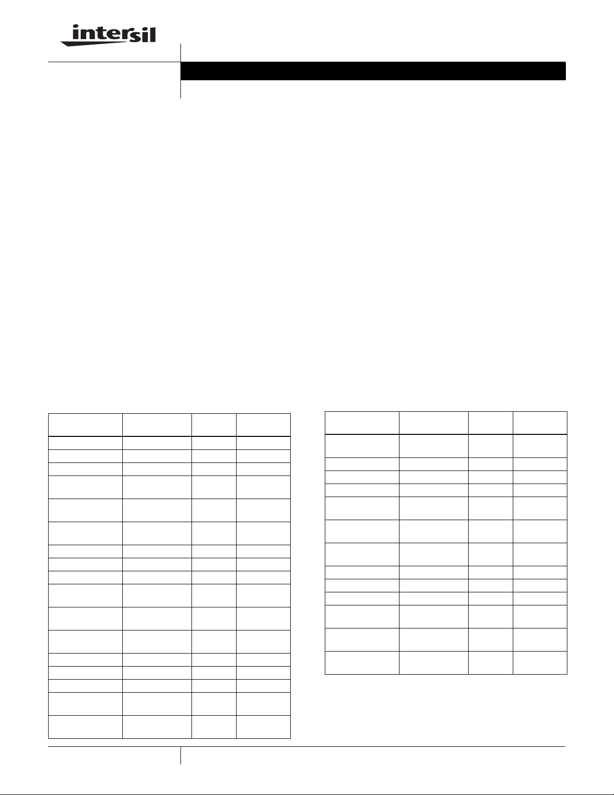
Ordering Information
PART NUMBER PACKAGE
EL5224IL 24-Pin QFN MDP0046
EL5224IL-T7 24-Pin QFN 7” MDP0046
EL5224IL-T13 24-Pin QFN 13” MDP0046
EL5224ILZ
(See Note)
EL5224ILZ-T7
(See Note)
EL5224ILZ-T13
(See Note)
EL5224IRE 24-Pin HTSSOP - MDP0048
EL5224IRE-T7 24-Pin HTSSOP 7” MDP0048
EL5224IRE-T13 24-Pin HTSSOP 13” MDP0048
EL5224IREZ
(See Note)
EL5224IREZ-T7
(See Note)
EL5224IREZ-T13
(See Note)
EL5324IL 32-Pin QFN MDP0046
EL5324IL-T7 32-Pin QFN 7” MDP0046
EL5324IL-T13 32-Pin QFN 13” MDP0046
EL5324ILZ
(See Note)
EL5324ILZ-T7
(See Note)
24-Pin QFN
(Pb-free)
24-Pin QFN
(Pb-free)
24-Pin QFN
(Pb-free)
24-Pin HTSSOP
(Pb-free)
24-Pin HTSSOP
(Pb-free)
24-Pin HTSSOP
(Pb-free)
32-Pin QFN
(Pb-free)
32-Pin QFN
(Pb-free)
TAPE &
REEL PKG. DWG. #
MDP0046
7” MDP0046
13” MDP0046
- MDP0048
7” MDP0048
13” MDP0048
MDP0046
7” MDP0046
• Touch-screen displays
• Portable instrumentation
Ordering Information (Continued)
TAPE &
PART NUMBER PACKAGE
EL5324ILZ-T13
(See Note)
EL5324IRE 28-Pin HTSSOP - MDP0048
EL5324IRE-T7 28-Pin HTSSOP 7” MDP0048
EL5324IRE-T13 28-Pin HTSSOP 13” MDP0048
EL5324IREZ
(See Note)
EL5324IREZ-T7
(See Note)
EL5324IREZ-T13
(See Note)
EL5424IL 32-Pin QFN MDP0046
EL5424IL-T7 32-Pin QFN 7” MDP0046
EL5424IL-T13 32-Pin QFN 13” MDP0046
EL5424ILZ
(See Note)
EL5424ILZ-T7
(See Note)
EL5424ILZ-T13
(See Note)
NOTE: Intersil Pb-free products employ special Pb-free material sets; molding
compounds/die attach materials and 100% matte tin plate termination finish,
which are RoHS compliant and compatible with both SnPb and Pb- free soldering
operations. Intersil Pb-free products are MSL classified at Pb-free peak reflow
temperatures that meet or exceed the Pb-free requirements of IPC/JEDEC J
STD-020.
32-Pin QFN
(Pb-free)
28-Pin HTSSOP
(Pb-free)
28-Pin HTSSOP
(Pb-free)
28-Pin HTSSOP
(Pb-free)
32-Pin QFN
(Pb-free)
32-Pin QFN
(Pb-free)
32-Pin QFN
(Pb-free)
REEL PKG. DWG. #
13” MDP0046
- MDP0048
7” MDP0048
13” MDP0048
MDP0046
7” MDP0046
13” MDP0046
1
CAUTION: These devices are sensitive to electrostatic discharge; follow proper IC Handling Procedures.
1-888-INTERSIL or 1-888-352-6832
| Intersil (and design) is a registered trademark of Intersil Americas Inc.
Copyright Intersil Americas Inc. 2003, 2005. All Rights Reserved
All other trademarks mentioned are the property of their respective owners.
Page 2
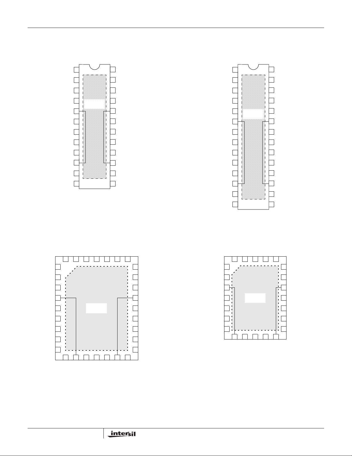
Pinouts
EL5224
(24-PIN HTSSOP)
TOP VIEW
EL5224, EL5324, EL5424
EL5324
(28-PIN HTSSOP)
TOP VIEW
VIN1
VIN2
VIN3
VIN4
VS+
VIN5
VIN6
VIN7
VIN8
VSA+
VINA+
NC
1
2
3
4
THERMAL
PAD
5
6
7
8
9
10
11
12
EL5324 & EL5424
(32-PIN QFN)
TOP VIEW
24
23
22
21
20
19
18
17
16
15
14
13
VOUT1
VOUT2
VOUT3
VOUT4
VS-
VOUT5
VOUT6
VOUT7
VOUT8
VSA-
VINA-
VOUTA
VIN1
VIN2
VIN3
VIN4
VIN5
VS+
VIN6
VIN7
VIN8
VIN9
VIN10
VSA+
VINA+
NC
1
2
3
4
5
THERMAL
6
7
8
9
10
11
12
13
EL5224
(24-PIN QFN)
TOP VIEW
PAD
28
27
26
25
24
23
22
21
20
19
18
17
16
1514
VOUT1
VOUT2
VOUT3
VOUT4
VOUT5
VS-
VOUT6
VOUT7
VOUT8
VOUT9
VOUT10
VSA-
VINA-
VOUTA
VIN3
VIN4
VIN5
VS+
VIN6
VIN7
VIN8
VIN9
VIN10
VIN2*
VIN1
VIN0
32
31
30
1
2
3
4
11
VSA+
THERMAL
12
VINA+
5
6
7
8
9
10
VIN11*
*Not available in EL5324
PAD
NC
29
13
VOUTA
VOUT0
28
14
VINA-
VOUT1
VOUT2*
25
VOUT3
24
VOUT4
23
VOUT5
22
VS-
21
VOUT6
20
VOUT7
19
VOUT8
18
VOUT9
VOUT10
17
15 27
16 26
VSA-
VOUT11*
VIN3
VIN4
VS+
VIN5
VIN6
VIN7
VIN8
VIN2
VIN1
NC
VOUT1
VOUT2
24
23
22
21
20
11
VINA-
19
VOUT3
18
VOUT4
17
VS-
16
VOUT5
15
VOUT6
14
VOUT7
13
VOUT8
12
VSA-
1
2
3
8
VSA+
THERMAL
PAD
9
10
VINA+
VOUTA
4
5
6
7
2
Page 3
EL5224, EL5324, EL5424
Absolute Maximum Ratings (T
Supply Voltage between V
Input Voltage . . . . . . . . . . . . . . . . . . . . . . . . . .V
Maximum Continuous Output Current (V
Maximum Continuous Output Current (V
CAUTION: Stresses above those listed in “Absolute Maximum Ratings” may cause permanent damage to the device. This is a stress only rating and operation of the
device at these or any other conditions above those indicated in the operational sections of this specification is not implied.
+ and VS- . . . . . . . . . . . . . . . . . . . .+18V
S
= 25°C)
A
- -0.5V, VS+ +0.5V
S
) . . . . . . . . . . 30mA
OUT0-9
). . . . . . . . . . . 150mA
OUTA
Power Dissipation . . . . . . . . . . . . . . . . . . . . . . . . . . . . . See Curves
Maximum Die Temperature . . . . . . . . . . . . . . . . . . . . . . . . . . +125°C
Storage Temperature . . . . . . . . . . . . . . . . . . . . . . . . -65°C to +150°C
Ambient Operating Temperature . . . . . . . . . . . . . . . . -40°C to +85°C
NOTE: All parameters having Min/Max specifications are guaranteed. Typ values are for information purposes only. Unless otherwise noted, all tests
are at the specified temperature and are pulsed tests, therefore: T
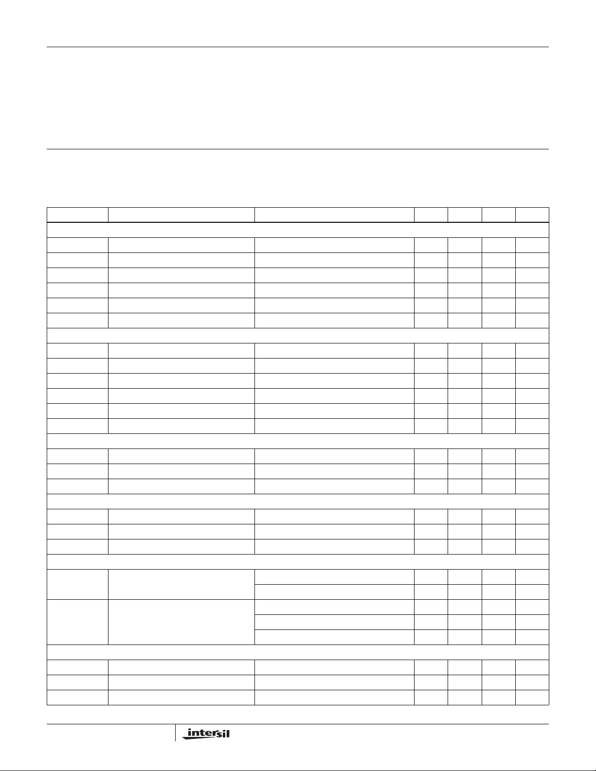
Electrical Specifications V
+ = +15V, VS- = 0, RL = 10kΩ, RF = RG = 20kΩ, CL = 10pF to 0V, Gain of V
S
= TC = T
J
A
= -1, and TA = 25°C Unless
COM
Otherwise Specified
PARAMETER DESCRIPTION CONDITIONS MIN TYP MAX UNIT
INPUT CHARACTERISTICS (REFERENCE BUFFERS)
V
OS
TCV
I
B
R
IN
C
IN
A
V
OS
Input Offset Voltage V
Average Offset Voltage Drift (Note 1) 5 µV/°C
Input Bias Current V
Input Impedance 1GΩ
Input Capacitance 1.35 pF
Voltage Gain 1V ≤ V
INPUT CHARACTERISTICS (V
V
OS
TCV
I
B
R
IN
C
IN
V
REG
OS
Input Offset Voltage V
Average Offset Voltage Drift (Note 1) 3 µV/°C
Input Bias Current V
Input Impedance 1GΩ
Input Capacitance 1.35 pF
Load Regulation V
COM
BUFFER)
= 0V 2 14 mV
CM
= 0V 2 50 nA
CM
≤ 14V 0.992 1.008 V/V
OUT
= 7.5V 1 4 mV
CM
= 7.5V 2 100 nA
CM
= 6V, -100mA < IL < 100mA -20 +20 mV
COM
OUTPUT CHARACTERISTICS (REFERENCE BUFFERS)
V
OL
V
OH
I
SC
OUTPUT CHARACTERISTICS (V
V
OL
V
OH
I
SC
Output Swing Low IL = 7.5mA 50 150 mV
Output Swing High IL = 7.5mA 14.85 14.95 V
Short Circuit Current 120 140 mA
BUFFER)
COM
Output Swing Low 50Ω to 7.5V 1 1.5 V
Output Swing High 50Ω to 7.5V 13.5 14 V
Short Circuit Current 160 mA
POWER SUPPLY PERFORMANCE
PSRR Power Supply Rejection Ratio Reference buffer V
buffer, VS from 5V to 15V 60 100 dB
V
COM
I
S
Total Supply Current EL5224 (no load) 5 6.8 8 mA
from 5V to 15V 55 80 dB
S
EL5324 (no load) 6 7.8 9.5 mA
EL5424 (no load) 7 8.8 11 mA
DYNAMIC PERFORMANCE (BUFFER AMPLIFIERS)
SR Slew Rate (Note 2) -4V ≤ V
t
S
BW -3dB Bandwidth R
Settling to +0.1% (AV = +1) (AV = +1), VO = 2V step 250 ns
= 10kΩ, CL = 10pF 12 MHz
L
≤ 4V, 20% to 80% 7 15 V/µs
OUT
3
Page 4
EL5224, EL5324, EL5424
Electrical Specifications V
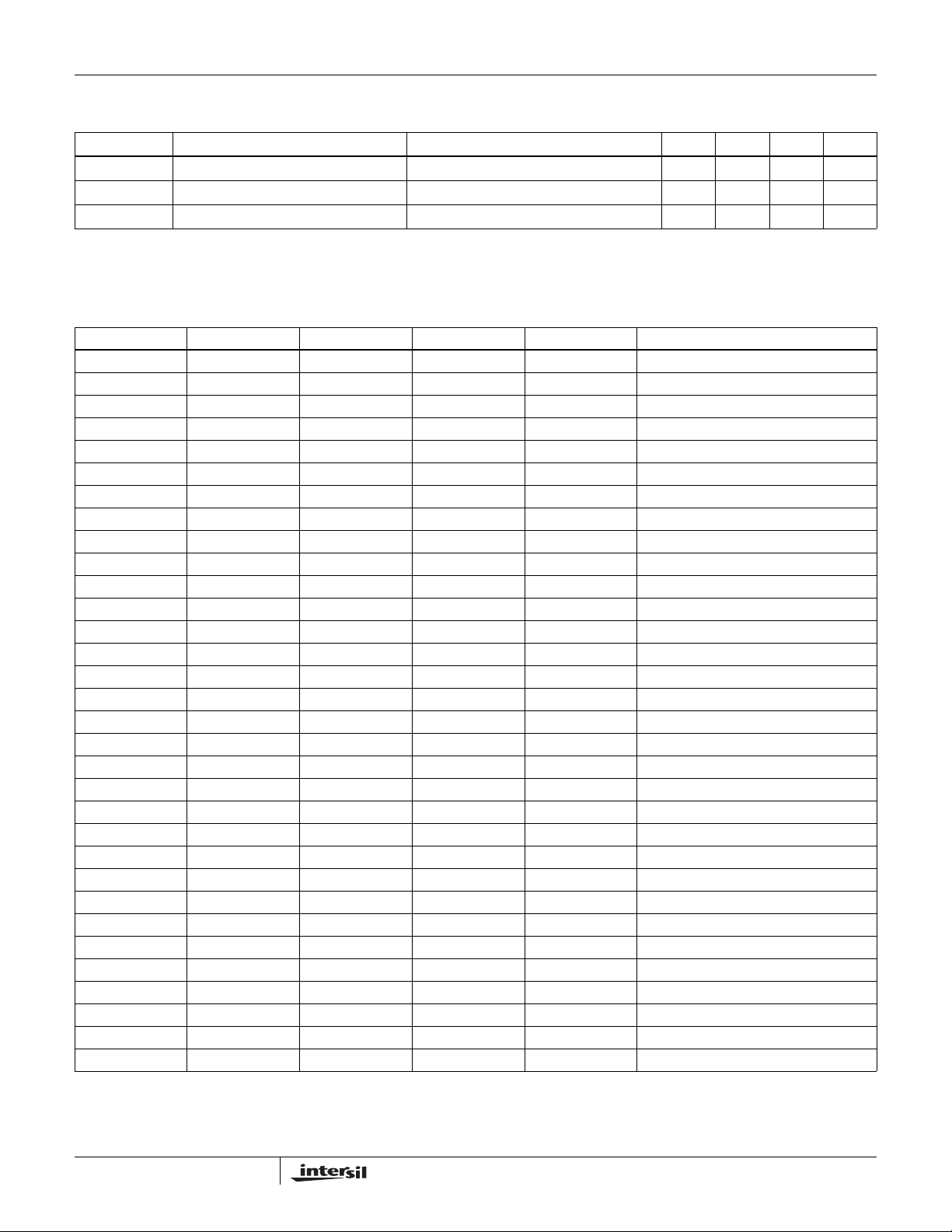
PARAMETER DESCRIPTION CONDITIONS MIN TYP MAX UNIT
GBWP Gain-Bandwidth Product RL = 10kΩ, CL = 10pF 8 MHz
PM Phase Margin R
CS Channel Separation f = 5MHz 75 dB
NOTES:
1. Measured over operating temperature range
2. Slew rate is measured on rising and falling edges
+ = +15V, VS- = 0, RL = 10kΩ, RF = RG = 20kΩ, CL = 10pF to 0V, Gain of V
S
Otherwise Specified (Continued)
= 10kΩ, CL = 10pF 50 °
L
= -1, and TA = 25°C Unless
COM
Pin Descriptions
24-PIN HTSSOP 24-PIN QFN 32-PIN QFN 28-PIN HTSSOP PIN NAME PIN FUNCTION
1 23 31 1 VIN1 Input
2 24 32 (Note 1) 2 VIN2 Input
3113VIN3Input
4224VIN4Input
5346VS+Power
6435VIN5Input
7557VIN6Input
8668VIN7Input
9779VIN8Input
10 8 11 12 VSA+ Power
11 9 12 13 VINA+ Positive input of V
12 22 29 14 NC Not connected
13 10 13 15 VOUTA Output of V
14 11 14 16 VINA- Negative input of V
15 12 15 17 VSA- Power
16 13 19 20 VOUT8 Output
17 14 20 21 VOUT7 Output
18 15 21 22 VOUT6 Output
19 16 23 24 VOUT5 Output
20 17 22 23 VS- Power
21 18 24 25 VOUT4 Output
22 19 25 26 VOUT3 Output
23 20 26 (Note 1) 27 VOUT2 Output
24 21 27 28 VOUT1 Output
8 10 VIN9 Input
9 11 VIN10 Input
10 (Note 1) VIN11 Input
16 (Note 1) VOUT11 Output
17 18 VOUT10 Output
18 19 VOUT9 Output
28 VOUT0 Output
30 VIN0 Input
NOTE:
1. Not available in EL5324IL
COM
COM
COM
4
Page 5

Typical Performance Curves
EL5224, EL5324, EL5424
20
VS=±7.5V
=10pF
C
L
10
0
-10
-20
NORMALIZED MAGNITUDE (dB)
-30
100K 1M 10M 100M
10kΩ
1kΩ
150Ω
562Ω
FREQUENCY (Hz)
FIGURE 1. FREQUENCY RESPONSE FOR VARIOUS RL
(BUFFER)
100
PSRR+
80
PSRR-
60
40
PSRR (dB)
VS=±7.5V
20
VS=±7.5V
=10kΩ
R
L
10
0
-10
-20
NORMALIZED MAGNITUDE (dB)
-30
100K 1M 10M 100M
47pF
FREQUENCY (Hz)
1000pF
100pF
12pF
FIGURE 2. FREQUENCY RESPONSE FOR VARIOUS CL
(BUFFER)
600
VS=±7.5V
=25°C
T
A
480
360
240
20
0
1K 10K 1M 10M
100K
FREQUENCY (Hz)
120
OUTPUT IMPEDANCE (Ω)
0
100K 1M 10M 100M
FREQUENCY (Hz)
FIGURE 3. PSRR vs FREQUENCY (BUFFER) FIGURE 4. OUTPUT IMPEDANCE vs FREQUENCY (BUFFER)
80
100
10
VOLTAGE NOISE (nV/√Hz)
1
10K 100K 10M 100M
1M
FREQUENCY (Hz)
FIGURE 5. INPUT NOISE SPECIAL DENSITY vs FREQUENCY
FIGURE 6. OVERSHOOT vs LOAD CAPACITANCE (BUFFER)
VS=±7.5V
70
R
=10kΩ
L
=100mV
V
IN
60
50
40
30
OVERSHOOT (%)
20
10
0
10 100 1K
CAPACITANCE (pF)
(BUFFER)
5
Page 6

EL5224, EL5324, EL5424
Typical Performance Curves (Continued)
10
VS=±7.5V
8
=10kΩ
R
L
=12pF
C
6
L
4
2
0
-2
STEP SIZE (V)
-4
-6
-8
-10
200 400 650
250 300 350 450 500 550 600
SETTLING TIME (ns)
0.018
VS=±5V
=10kΩ
R
0.016
0.014
0.012
THD + NOISE (%)
0.008
0.006
L
=2V
V
IN
P-P
0.01
1K 10K 100K
FREQUENCY (Hz)
FIGURE 7. SETTLING TIME vs STEP SIZE (BUFFER) FIGURE 8. TOTAL HARMONIC DISTORTION + NOISE vs
FREQUENCY (BUFFER)
12
10
8
(V)
6
OP-P
V
4
2
VS=±5V
=10kΩ
R
L
0
10K 100K 1M 10M
FREQUENCY (Hz)
4
2
0
-2
-4
VS=±7.5V
NORMALIZED MAGNITUDE (dB)
=1µF
C
L
-6
100 1K 100K
FREQUENCY (Hz)
AV=5
AV=1
1M10K
FIGURE 9. OUTPUT SWING vs FREQUENCY (BUFFER) FIGURE 10. FREQUENCY RESPONSE (V
0mA
5mA
0V
RS=0Ω
=200pF
C
L
RS=10Ω
=1nF
C
L
RS=10Ω
=4.7nF
C
L
M=1µs/DIV
=±7.5V
V
S
=0V
V
IN
5mA/DIV
500mV/DIV
FIGURE 11. TRANSIENT LOAD REGULATION - SOURCING
(BUFFER)
5mA
0mA
RS=10Ω
=1nF
C
0V
M=1µs/DIV
=±7.5V
V
S
=0V
V
IN
RS=0Ω
=200pF
C
L
L
RS=10Ω
C
L
=4.7nF
FIGURE 12. TRANSIENT LOAD REGULATION - SINKING
(BUFFER)
6
)
COM
5mA/DIV
500mV/DIV
Page 7

EL5224, EL5324, EL5424
Typical Performance Curves (Continued)
M=4µs/DIV, V
0mA
-100mA
0V
CL=1µF
=±7.5V, VIN=0V
S
100mA/DIV
20mV/DIV
FIGURE 13. TRANSIENT LOAD REGULATION - SOURCING
(V
)
COM
V
=±7.5V, RL=10kΩ, CL=12pF
S
50mV/DIV
M=4µs/DIV, V
100mA
0mA
0V
CL=1µF
=±7.5V, VIN=0V
S
100mA/DIV
20mV/DIV
FIGURE 14. TRANSIENT LOAD REGULATION - SINKING
(V
)
COM
VS=±7.5V
1V/DIV
200ns/DIV
FIGURE 15. SMALL SIGNAL TRANSIENT RESPONSE
(BUFFER)
JEDEC JESD51-7 HIGH EFFECTIVE THERMAL
CONDUCTIVITY (4-LAYER) TEST BOARD, QFN EXPOSED
DIEPAD SOLDERED TO PCB PER JESD51-5
3
2.5
2.703W
2
1.5
1
POWER DISSIPATION (W)
0.5
0
0 25507510012515085
2.857W
QFN32
=35°C/W
θ
JA
QFN24
=37°C/W
θ
JA
AMBIENT TEMPERATURE (°C)
FIGURE 17. PACKAGE POWER DISSIPATION vs AMBIENT
TEMPERATURE
1µs/DIV
FIGURE 16. LARGE SIGNAL TRANSIENT RESPONSE
(BUFFER)
JEDEC JESD51-3 AND SEMI G42-88 (SINGLE
LAYER) TEST BOARD
0.8
0.7
714mW
0.6
0.5
0.4
0.3
0.2
POWER DISSIPATION (W)
0.1
θ
0
0 25 50 75 125 150
758mW
QFN32
=132°C/W
θ
JA
QFN24
=140°C/W
JA
10085
AMBIENT TEMPERATURE (°C)
FIGURE 18. PACKAGE POWER DISSIPATION vs AMBIENT
TEMPERATURE
7
Page 8

EL5224, EL5324, EL5424
Typical Performance Curves (Continued)
JEDEC JESD51-7 HIGH EFFECTIVE THERMAL
CONDUCTIVITY TEST BOARD. HTSSOP EXPOSED
DIEPAD SOLDERED TO PCB PER JESD51-5
3.5
3
3.030W
2.5
2
1.5
1
POWER DISSIPATION (W)
0.5
0
0255075100 150
3.333W
HTSSOP28
=30°C/W
θ
JA
HTSSOP24
θ
=33°C/W
JA
AMBIENT TEMPERATURE (°C)
12585
FIGURE 19. PACKAGE POWER DISSIPATION vs AMBIENT
TEMPERATURE
Applications Information
Product Description
The EL5224, EL5324, and EL5424 unity gain buffers and
100mA V
CMOS process. The buffers exhibit rail-to-rail input and
output capability and has low power consumption (600µA
per buffer). When driving a load of 10kΩ and 12pF, the
buffers have a -3dB bandwidth of 12MHz and exhibits
18V/µs slew rate. The V
input. The output can be driving to within 2V of each supply
rail. With a 1µF capacitance load, the GBWP is about 1MHz.
Correct operation is guaranteed for a supply range of 4.5V to
16.5V.
amplifier are fabricated using a high voltage
COM
amplifier exhibits rail-to-rail
COM
JEDEC JESD51-3 LOW EFFECTIVE THERMAL
CONDUCTIVITY TEST BOARD
1
0.9
0.8
833mW
0.7
0.6
0.5
0.4
0.3
0.2
POWER DISSIPATION (W)
0.1
0
0 255075100 150
909mW
HTSSOP28
θ
=110°C/W
JA
HTSSOP24
=120°C/W
θ
JA
85
AMBIENT TEMPERATURE (°C)
125
FIGURE 20. PACKAGE POWER DISSIPATION vs AMBIENT
TEMPERATURE
5V
5V
10µs
VS=±5V
=25°C
T
A
=10V
V
IN
P-P
OUTPUT INPUT
FIGURE 21. OPERATION WITH RAIL-TO-RAIL INPUT AND
OUTPUT
The Use of the Buffers
The output swings of the buffers typically extend to within
100mV of positive and negative supply rails with load
currents of 5mA. Decreasing load currents will extend the
output voltage range even closer to the supply rails.
Figure 21 shows the input and output waveforms for the
device. Operation is from ±5V supply with a 10kΩ load
connected to GND. The input is a 10V
output voltage is approximately 9.985V
8
sinusoid. The
P-P
.
P-P
SHORT-CIRCUIT CURRENT LIMIT
The buffers will limit the short circuit current to ±120mA if the
output is directly shorted to the positive or the negative
supply. If an output is shorted indefinitely, the power
dissipation could easily increase such that the device may
be damaged. Maximum reliability is maintained if the output
continuous current never exceeds ±30mA. This limit is set by
the design of the internal metal interconnects.
OUTPUT PHASE REVERSAL
The buffers are immune to phase reversal as long as the
input voltage is limited from V
- -0.5V to VS+ +0.5V.
S
Figure 22 shows a photo of the output of the device with the
input voltage driven beyond the supply rails. Although the
device's output will not change phase, the input's
overvoltage should be avoided. If an input voltage exceeds
supply voltage by more than 0.6V, electrostatic protection
diodes placed in the input stage of the device begin to
conduct and overvoltage damage could occur.
Page 9

1V
10µs
EL5224, EL5324, EL5424
V
BOOST
R
1
IPCOM
INCOM
R
2
+
V
SSCOM
V
DDCOM
V
COM
1µF CERAMIC
LOW ESR
V
COM
VS=±2.5V
=25°C
T
A
V
=6V
IN
1V
FIGURE 22. OPERATION WITH BEYOND-THE-RAILS INPUT
P-P
UNUSED BUFFERS
It is recommended that any unused buffers have their inputs
tied to the ground plane.
DRIVING CAPACITIVE LOADS
The buffers can drive a wide range of capacitive loads. As
load capacitance increases, however, the -3dB bandwidth of
the device will decrease and the peaking increase. The
buffers drive 10pF loads in parallel with 10kΩ with just 1.5dB
of peaking, and 100pF with 6.4dB of peaking. If less peaking
is desired in these applications, a small series resistor
(usually between 5Ω and 50Ω) can be placed in series with
the output. However, this will obviously reduce the gain
slightly. Another method of reducing peaking is to add a
snubber circuit at the output. A snubber is a shunt load
consisting of a resistor in series with a capacitor. Values of
150Ω and 10nF are typical. The advantage of a snubber is
that it does not draw any DC load current or reduce the gain.
The Use of V
The V
amplifier is designed to control the voltage on the
COM
COM
Amplifier
back plate of an LCD display. This plate is capacitively
coupled to the pixel drive voltage which alternately cycles
positive and negative at the line rate for the display. Thus the
amplifier must be capable of sourcing and sinking capacitive
pulses of current, which can occasionally be quite large (a
few 100mA for typical applications).
A simple use of the V
amplifier is as a voltage follower,
COM
as illustrated in Figure 23. Here, a voltage, corresponding to
the mid-DAC potential, is generated by a resistive divider
and buffered by the amplifier. The amplifier's stability is
designed to be dominated by the load capacitance, thus for
very short duration pulses (< 1µs) the output capacitor
supplies the current. For longer pulses the V
COM
amplifier
supplies the current. By virtue of its high transconductance
which progressively increases as more current is drawn, it
can maintain regulation within 5mV as currents up to 100mA
are drawn, while consuming only 2mA of quiescent current.
FIGURE 23. V
USED AS A VOLTAGE BUFFER
COM
Alternatively, the back plate potential can be generated by a
DAC and the V
amplifier used to buffer the DAC
COM
voltage, with gain if necessary. This is shown in Figure 24. In
this case, the effective transconductance of the feedback is
reduced, thus the amplifier will be more stable, but regulation
will be degraded by the feedback factor.
V
BOOST
FROM DAC
FIGURE 24. V
+
R
1
R
2
USED AS A BUFFER WITH GAIN
COM
V
COM
1µF CERAMIC
LOW ESR
CHOICE OF OUTPUT CAPACITOR
A 1µF ceramic capacitor with low ESR is recommended for
this amplifier. (For example, GRM42_ 6X7R105K16). This
capacitor determines the stability of the amplifier. Reducing it
will make the amplifier less stable, and should be avoided.
With a 1µF capacitor, the unity gain bandwidth of the
amplifier is close to 1MHz when reasonable currents are
being drawn. (For lower load currents, the gain and hence
bandwidth progressively decreases.) This means the active
trans-conductance is:
2π 1µ F1MHz×× 6.28S=
This high transconductance indicates why it is important to
have a low ESR capacitor.
If:
ESR 6.28 1>×
then the capacitor will not force the gain to roll off below
unity, and subsequent poles can affect stability. The
recommended capacitor has an ESR of 10mΩ, but to this
must be added the resistance of the board trace between the
capacitor and the sense connection - therefore this should
be kept short, as illustrated in Figure 21, by the diagonal line
to the capacitor. Also ground resistance between the
capacitor and the base of R
must be kept to a minimum.
2
These constraints should be considered when laying out the
PCB.
9
Page 10

EL5224, EL5324, EL5424
If the capacitor is increased above 1µF, stability is generally
improved and short pulses of current will cause a smaller
“perturbation” on the V
voltage. The speed of response
COM
of the amplifier is however degraded as its bandwidth is
decreased. At capacitor values around 10µF, a subtle
interaction with internal DC gain boost circuitry will decrease
the phase margin and may give rise to some overshoot in
the response. The amplifier will remain stable though.
RESPONSE TO HIGH CURRENT SPIKES
The V
amplifier's output current is limited to 150mA.
COM
This limit level, which is roughly the same for sourcing and
sinking, is included to maintain reliable operation of the part.
It does not necessarily prevent a large temperature rise if the
current is maintained. (In this case the whole chip may be
shut down by the thermal trip to protect functionality.) If the
display occasionally demands current pulses higher than
this limit, the reservoir capacitor will provide the excess and
the amplifier will top the reservoir capacitor back up once the
pulse has stopped. This will happen on the µs time scale in
practical systems and for pulses 2 or 3 times the current
limit, the V
voltage will have settled again before the
COM
next line is processed.
Power Dissipation
With the high-output drive capability of the EL5224, EL5324,
and EL5424 buffer, it is possible to exceed the 125°C
“absolute-maximum junction temperature” under certain load
current conditions. Therefore, it is important to calculate the
maximum junction temperature for the application to
determine if load conditions need to be modified for the
buffer to remain in the safe operating area.
The maximum power dissipation allowed in a package is
determined according to:
T
- T
P
DMAX
JMAX
---------------------------------------------=
where:
•T
•T
• θ
•P
= Maximum junction temperature
JMAX
= Maximum ambient temperature
AMAX
= Thermal resistance of the package
JA
= Maximum power dissipation in the package
DMAX
The maximum power dissipation actually produced by an IC
is the total quiescent supply current times the total power
supply voltage, plus the power in the IC due to the loads, or:
P
DMAX
V
[ I
SA
ΣiV
SAAVSA
AMAX
Θ
JA
[ I
S
SMAXV(S
( + - V
OUTA
+ - V
) ILA]×+×
OUT
i) I
LOAD
i]
+×+××=
when sourcing, and:
P
DMAX
V
[ I
SA
ΣiV
[ I
S
( + - V
SAAVSA
SMAXV(OUT
OUTA
) ILA]×+×
i - VS-) I
LOAD
i]
+×+××=
when sinking.
where:
• i = 1 to total number of buffers
•VS = Total supply voltage of buffer
= Total supply voltage of V
•V
SA
•I
•I
•V
•V
•I
•I
If we set the two P
can solve for the R
= Maximum quiescent current per channel
SMAX
= Maximum quiescent current of V
SA
i = Maximum output voltage of the application
OUT
= Maximum output voltage of V
OUTA
i = Load current of buffer
LOAD
= Load current of V
LA
COM
equations equal to each other, we
DMAX
's to avoid device overheat. The
LOAD
COM
COM
COM
package power dissipation curves provide a convenient way
to see if the device will overheat. The maximum safe power
dissipation can be found graphically, based on the package
type and the ambient temperature. By using the previous
equation, it is a simple matter to see if P
DMAX
exceeds the
device's power derating curves.
Power Supply Bypassing and Printed Circuit
Board Layout
As with any high frequency device, good printed circuit
board layout is necessary for optimum performance. Ground
plane construction is highly recommended, lead lengths
should be as short as possible, and the power supply pins
must be well bypassed to reduce the risk of oscillation. For
normal single supply operation, where the V
are connected to ground, two 0.1µF ceramic capacitors
should be placed from V
+ and VSA+ pins to ground. A
S
4.7µF tantalum capacitor should then be connected from
V
+ and VSA+ pins to ground. One 4.7µF capacitor may be
S
used for multiple devices. This same capacitor combination
should be placed at each supply pin to ground if split
supplies are to be used. Internally, V
shorted together and V
- and VSA- are shorted together. To
S
avoid high current density, the V
S
+ pin and VSA+ pin must
S
be shorted in the PCB layout. Also, the V
must be shorted in the PCB layout.
Important Note: The metal plane used for heat sinking of
the device is electrically connected to the negative
supply potential (V
- and VSA-). If VS- and VSA- are tied
S
to ground, the thermal pad can be connected to ground.
Otherwise, the thermal pad must be isolated from any
other power planes.
- and VSA- pins
S
+ and VSA+ are
- pin and VSA- pin
S
10
Page 11

EL5224, EL5324, EL5424
Package Outline Drawing (HTSSOP)
11
Page 12

Package Outline Drawing (QFN)
EL5224, EL5324, EL5424
NOTE: The package drawings shown here may not be the latest versions. For the latest revisions, please refer to the Intersil website at
www.intersil.com/design/packages/elantec
All Intersil U.S. products are manufactured, assembled and tested utilizing ISO9000 quality systems.
Intersil Corporation’s quality certifications can be viewed at www.intersil.com/design/quality
Intersil products are sold by description only. Intersil Corporation reserves the right to make changes in circuit design, software and/or specifications at any time without
notice. Accordingly, the reader is cautioned to verify that data sheets are current before placing orders. Information furnished by Intersil is believed to be accurate and
reliable. However, no responsibility is assumed by Intersil or its subsidiaries for its use; nor for any infringements of patents or other rights of third parties which may result
from its use. No license is granted by implication or otherwise under any patent or patent rights of Intersil or its subsidiaries.
For information regarding Intersil Corporation and its products, see www.intersil.com
12
 Loading...