

OBSOLETE PRODUCT
POSSIBLE SUBSTITUTE PRODUCT
CA3089E
CA3189
[ /Title
(CA31
89)
/Subject
(FM
IF System)
/Autho
r ()
/Keywords
(Harris
Semiconductor,
FM IF
amplifier,
quadrat
ure
detector,
tuning
meter
output,
limiter,
AFC
circuit,
AGC
circuit,
muting circuit,
industrial
tempera-
May 1999
Features
• Includes IF Amplifier, Quadrature Detector, AF
Preamplifier, and Specific Circuits for AGC, AFC, Tuning Meter, Deviation-Noise Muting, and ON Channel
Detector
• FM IF Amplifier Applications in High-Fidelity,
Automotive, and Communications Receivers
• Exceptional Limiting Sensitivity -12µV (Typ) at -3dB
Point
• Low Distortion -0.1% (Typ) (with Double-Tuned Coil)
• Single-Coil Tuning Capability
• Improved S + N/N Ratio
• Externally Programmable Recovered Audio Level
• Provides Specific Signal for Control of Interchannel
Muting (Squelch)
• Provides Specific Signal for Direct Drive of a Tuning
Meter
• On Channel Step for Search Control
• Provides Programmab le AGC Voltage for RF Amplifier
• Provides a Specific Circuit for Flexible Audio Output
• Internal Supply Voltage Regulators
• Externally Programmable “On” Channel Step Width,
and Deviation at Which Muting Occurs
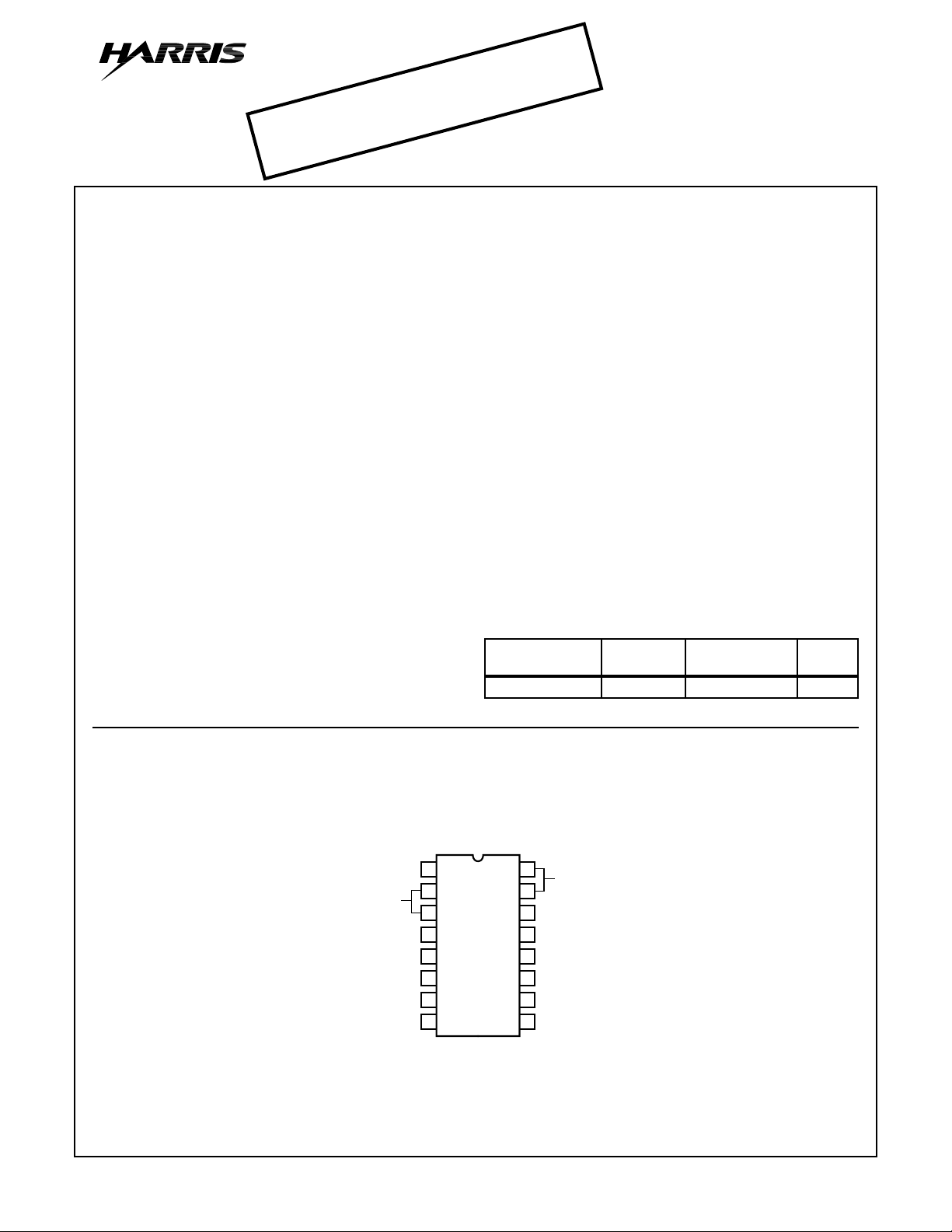
Pinout
IF IN
INPUT
BYPASS
FRAME
MUTE CONTROL
AUDIO OUT
AFC OUT
IF OUT
CA3189
TOP VIEW
1
2
3
4
5
6
7
8
FM IF System
Description
The Harris CA3189E is a monolithic integrated circuit that
provides all the functions of a comprehensive FM-lF system.
The block diagram of the CA3189E includes a three-stage
FM-lF amplifier/limiter configuration with level detectors for
each stage, a doubly-balanced quadrature FM detector and
an audio amplifier that features the optional use of a muting
(squelch) circuit.
The advanced circuit design of the IF system includes desirable deluxe features such as programmable delayed AGC
for the RF tuner , an AFC drive circuit, and an output signal to
drive a tuning meter and/or provide stereo switching logic. In
addition, internal power-supply regulators maintain a nearly
constant current drain over the voltage supply range of
+8.5V to +16V.
The CA3189E is ideal for high-fidelity operation. Distortion in
a CA3189E FM-lF System is primarily a function of the
phase linearity characteristic of the outboard detector coil.
The CA3189E has all the features of the CA3089E plus additions. See CA3189E features compared to the CA3089E in
Table 1.
Part Number Information
TEMP.
PART NUMBER
CA3189E -40 to 85 16 Ld PDIP E16.3
(PDIP)
16
DELAYED AGC
15
SUBSTRATE (GND)
14
TUNING
13
METER OUT
MUTE LOGIC
12
V+
11
REF BIAS
10
QUADRATURE
9
INPUT
RANGE (oC) PACKAGE
PKG.
NO.
CAUTION: These devices are sensitive to electrostatic discharge. Users should follow proper IC Handling Procedures.
1-800-4-HARRIS or 407-727-9207
| Copyright © Harris Corporation 1999
1
File Number 1046.4
CA3189
Absolute Maximum Ratings Thermal Information
DC Supply Voltage
(Between Terminals 11 and 4) . . . . . . . . . . . . . . . . . . . . . . . . 16V
(Between Terminals 11 and 14) . . . . . . . . . . . . . . . . . . . . . . . 16V
DC Current (Out of Terminal 15) . . . . . . . . . . . . . . . . . . . . . . . .2mA
Operating Conditions
Temperature Range . . . . . . . . . . . . . . . . . . . . . . . . . -40oC to 85oC
CAUTION: Stresses above those listed in “Absolute Maximum Ratings” may cause permanent damage to the device. This is a stress only rating and operation
of the device at these or any other conditions above those indicated in the operational sections of this specification is not implied.
NOTE:
1. θJA is measured with the component mounted on an evaluation PC board in free air.
Thermal Resistance (Typical, Note 1) θJA (oC/W)
PDIP Package. . . . . . . . . . . . . . . . . . . . . . . . . . . . . 90
Maximum Junction Temperature (Plastic Package) . . . . . . . .150oC
Maximum Storage Temperature Range . . . . . . . . . -65oC to 150oC
Maximum Lead Temperature (Soldering 10s) . . . . . . . . . . . . 300oC
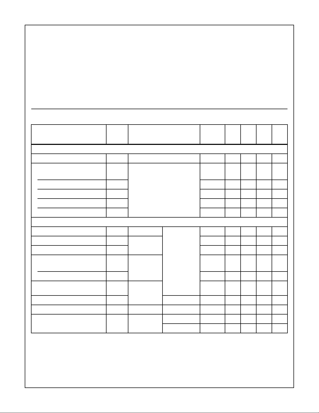
Electrical Specifications T
= 25oC, V+ = 12V
A
CIRCUIT
OR FIG.
PARAMETER SYMBOL TEST CONDITIONS
NO. MIN TYP MAX UNITS
DC SPECIFICATIONS
Quiescent Circuit Current I
No Signal Input, Non Muted 1, 2 20 31 40 mA
11
DC Voltages No Signal Input, Non Muted
Terminal 1 (IF Input) V
Terminal 2 (AC Return to Input) V
Terminal 3 (DC Bias to Input) V
Terminal 15 (RF AGC) V
Terminal 10 (DC Reference) V
1
2
3
15
10
1, 2 1.2 1.9 2.4 V
1, 2 1.2 1.9 2.4 V
1, 2 1.2 1.9 2.4 V
1, 2 7.5 9.5 11 V
1, 2 5 5.6 6 V
DYNAMIC SPECIFICATIONS
Input Limiting Voltage (-3dB Point) VI(lim) fO = 10.7MHz,
f
. = 400Hz,
AM Rejection (Terminal 6) AMR VIN = 0.1V,
MOD
Deviation ±75kHz
1, 2 - 12 25 µV
1, 2 45 55 - dB
AM Mod. = 30%
Recovered AF Voltage (Terminal 6) VO(AF) 1, 2 325 500 650 mV
Total Harmonic Distortion (Note 2)
Single Tuned (Terminal 6) THD VIN = 0.1V 1 - 0.5 1 %
Double Tuned (Terminal 6) THD 2 - 0.1 - %
Signal Plus Noise to Noise Ratio
S + N/N VIN = 0.1V 1, 2 65 72 - dB
(Terminal 6)
Deviation Mute Frequency f
RF AGC Threshold V
On Channel Step V
DEV
16
VIN = 0.1V f
12
f
= 0 1, 5, 6 - ±40 - kHz
MOD
1, 2 - 1.25 - V
< ±40kHz 1 - 0 - V
DEV
f
> ±40kHz 1 - 5.6 - V
DEV
NOTE:
2. THD characteristics are essentially a function of the phase characteristics of the network connected between Terminals 8, 9, and 10.
2

CA3189
TABLE 1. CA3189E FEATURES COMPARED TO CA3089E
FEATURES CA3189E CA3089E
Low Limiting Sensitivity (12µV Typ) Yes Yes
Low Distortion Yes Yes
Single-Coil Tuning Capability Yes Yes
Programmable Audio Level Yes No
S/N Mute Yes Yes
Deviation Mute Yes No
Flexible AFC Yes Yes
Programmable AGC Threshold and Voltage Yes No
Typical S + N/N > 70 dB Yes No
Meter Drive Voltage Depressed at Very Low Signal Levels Yes No
On-Channel Step Control Voltage Yes No
Test Circuits
L
(NOTE
SIGNAL
INPUT
VOLTAGE
PIN 13
0.01µF
0.02
TO
µF
47K
0.05µF
51
V+ = 12V
22µH
11
8
1
3
0.01
µF
2
16
14
4
10
TUNING METER
9
CA3189E
15
0.01
µF
K
4)
C
100
pF
3.9K
13
8.2K
10
0.01
µF
33K
150µA
FULL
SCALE
10µF
10µF
5K
AFC
7
OUT
6
C
(NOTE
12
5
5)
1µF
22K
AUDIO
OUT
470
0.33µF
10K
NOTES:
3. All resistance values are in ohms.
4. L tunes with 100pF (C) at 10.7MHz. Q0 (unloaded)≅ 75 (T OKO No .
KACS K586HM or equivalent).
5. C = 0.01µF for 50µs deemphasis (Europe).
C = 0.015µF for 75µs deemphasis (USA).
FIGURE 1. TEST CIRCUIT FOR CA3189E USING A SINGLE-
TUNED DETECTOR COIL
3K
100
pF
C
1
100
8.2K
µF
C
2
pF
13
T (NOTE 7)
8.2K
10
5
0.01
µF
33K
150µA
FULL
SCALE
12
22K
7
6
1µF
10µF
AFC
5K
OUT
(NOTE 9)
470
10K
C
AUDIO
OUT
0.33µF
SIGNAL
INPUT
VOLTAGE
PIN 13
0.01µF
0.02
TO
0.05µF
µF
47K
V+ = 12V
11
1
51
3
0.01
µF
2
16
4
TUNING METER
22µH
8
CA3189E
15
14
10
K
9
0.01
NOTES:
6. All resistance values are in ohms.
7. T: PRI. - Q0 (unloaded) ≅ 75 (tunes with 100pF (C1) 20↑ of 34e on
7
/32” dia. form. SEC. - Q0 (unloaded) ≅ 75 (tunes with 100pF (C2)
20↑ of 34e on7/32” dia. form. kQ (percent of critical coupling) ≅
70% (Adjusted for coil voltage (VC) = 150mV).
8. Above values permit proper operation of mute (squelch) circuit
“E” type slugs, spacing 4mm.
9. C = 0.01µF for 50µs deemphasis (Europe) C = 0.015µF for 75µs
deemphasis (USA).
FIGURE 2. TEST CIRCUIT FOR CA3189E USING A DOUBLE-
TUNED DETECTOR COIL
10µF
3
 Loading...