


OBSOLETE PRODUCT
CA3154
[ /Title
(CA31
54)
/Subject
(TV
Sync/A
GC/Ho
rizontal Signal
Processor)
/Autho
r ()
/Keywords
(Harris
Semiconductor,
TV
sync
processor,
horizontal
oscillator,
horizontal
processor,
sync
separator,
AFC
circuit,
AGC
cir-
May 1999
NO RECOMMENDED REPLACEMENT
Call Central Applications 1-800-442-7747
or email: centapp@harris.com
Features
• Horizontal Oscillator with AFC
• Sync Separator with Noise Immunity
• Strobed AGC System
• lF AGC Output
• Delayed Outputs for Forward or Reverse AGC Tuners
• Internal Noise Threshold
• High-Impedance Video Input
• Choice of Dual External Time Constants for Sync
Separator Noise Immunity
• RF AGC Delay Externally Controlled
• Output Short-Circuit Protection
Part Number Information
TEMP.
PART NUMBER
CA3154E -40 to 85 16 Ld PDIP E16.3
RANGE (oC) PACKAGE
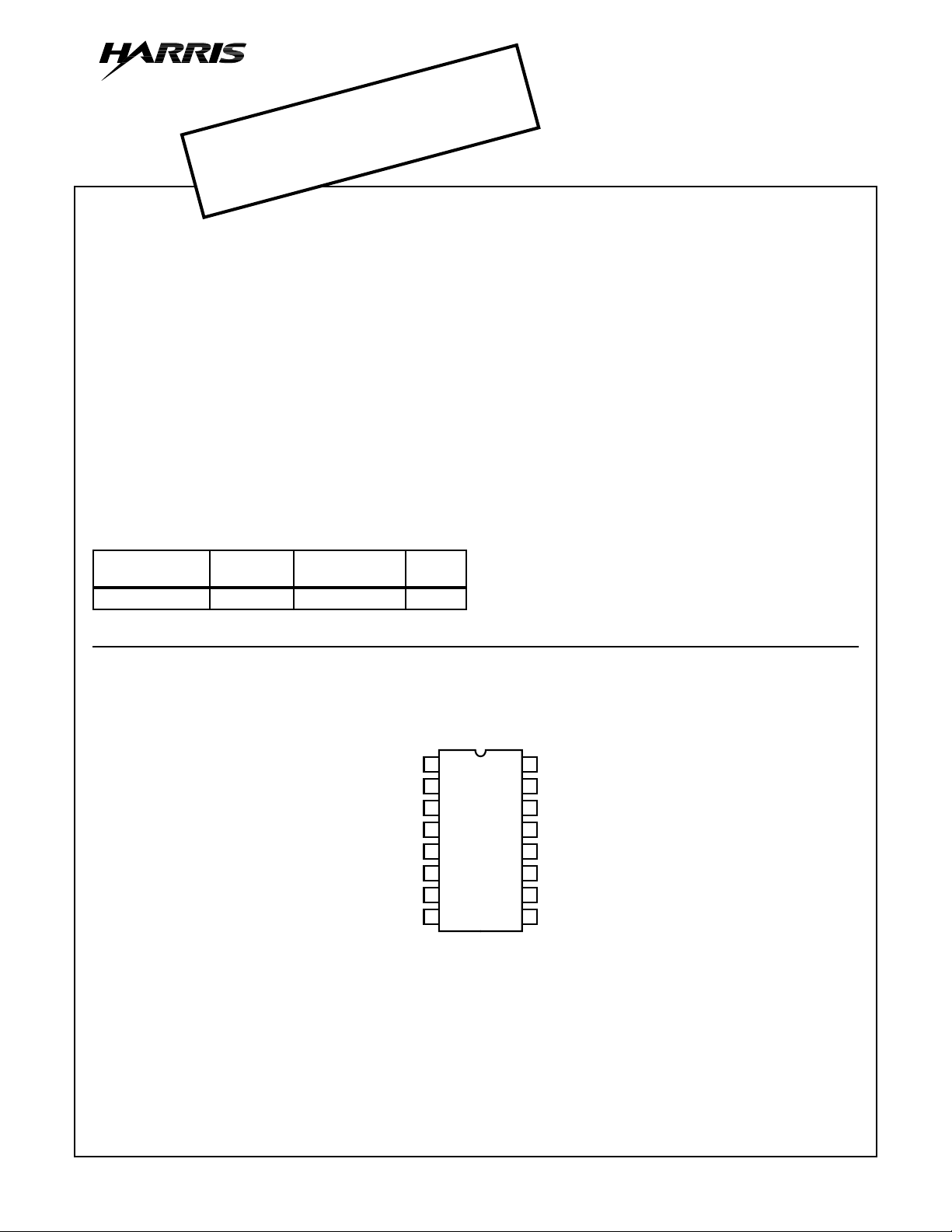
Pinout
VIDEO INPUT
SYNC SEP
COMP SYNC INPUT
HORIZ SAWTOOTH INPUT
GND
OSC PHASE INPUT
OSC QUAD INPUT
OSC OUTPUT
TV Sync/AGC/Horizontal Signal Processor
Description
The CA3154 is a monolithic integrated circuit TV signal
processor designed for use in color or monochrome
receivers. Circuit functions include a horizontal oscillator with
AFC, a sync separator, and a keyed AGC system. The AGC
system provides output signals for IF (reverse) and tuner
(forward and/or reverse). The wide frequency-range
horizontal oscillator has high stability at 503.5kHz. When the
CA3154 is used in conjunction with horizontal/vertical
countdown circuits, the need for horizontal and vertical hold
controls is eliminated.
PKG.
NO.
CA3154
(PDIP)
TOP VIEW
16
1
2
3
4
5
6
7
8
HORIZ PULSE INPUT
15
AGC FILTER
14
IF GAIN CLAMP
13
IF AGC
12
TUNER REV. AGC
TUNER FWD AGC
11
10
HORIZ AFC FILTER
9
SUPPLY VOLTAGE
CAUTION: These devices are sensitive to electrostatic discharge. Users should follow proper IC Handling Procedures.
© Harris Corporation 1999
Copyright
8-42
File Number 1183.2
CA3154
Absolute Maximum Ratings Thermal Information
DC Supply Voltage (V+ to V-) . . . . . . . . . . . . . . . . . . . . . . . . . . . 15V
Operating Conditions
Temperature Range . . . . . . . . . . . . . . . . . . . . . . . . . . -40oC to 85oC
CAUTION: Stresses above those listed in “Absolute Maximum Ratings” may cause permanent damage to the device. This is a stress only rating and operation
of the device at these or any other conditions above those indicated in the operational sections of this specification is not implied.
NOTE:
1. θJA is measured with the component mounted on an evaluation PC board in free air.
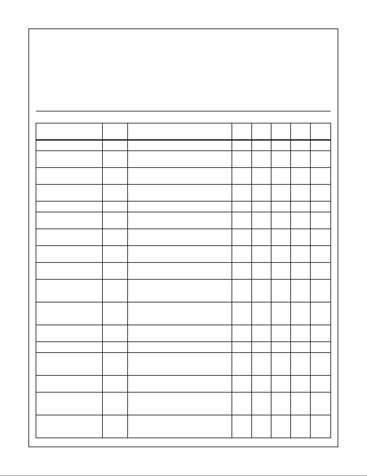
Electrical Specifications Terminal 5 to GND, and Terminal 9 to +12V, Unless Otherwise Specified
Thermal Resistance (Typical, Note 1) θJA (oC/W)
PDIP Package. . . . . . . . . . . . . . . . . . . . . . . . . . . . . 80
Maximum Junction Temperature (Plastic Package) . . . . . . . . 150oC
Maximum Storage Temperature Range . . . . . . . . . .-65oC to 150oC
Maximum Lead Temperature (Soldering 10s) . . . . . . . . . . . . . 300oC
PARAMETER SYMBOL
Power Supply Current I
Video Inverter Voltage V
TEST CONDITIONS
(TERMINALS CONNECTED AS SHOWN BELOW)
Measure (9) 25 10 - 22 mA
9
(1) to +4V, (2) 12kΩ to GND, (3) 27kΩ to GND,
2
TEMP
(oC) MIN TYP MAX UNITS
25 5.2 - 6.4 V
Measure (2)
Sync Separator High Output
Voltage
Sync Separator Low Output
V
(1) to +4V, (2) 12kΩ to GND, (3) 27kΩ to GND,
3H
25 10.7 - - V
Measure (2)
V
(1) to +4V, (3) 27kΩ to GND, Measure (3) 25 - - 1.3 V
3L
Voltage
Video Noise Clamp Voltage V3 Clamp (1) to +3.1V, (3) 27kΩ to GND, Measure (3) 25 10.7 - - V
AGC Discharge Current I
Discharge
AGC Charge Current I
(1) to +4.4V, (2) 10kΩ to GND, (15) 470Ω to
15
25 0.6 - 1.4 mA
+6V, (16) 27kΩ to 12V, Measure (15)
(1) to +3.45V, Otherwise, Same as Above 25 -2.1 - -4.8 mA
15
Charge
AGC Comparator Leakage I
Leakage
AGC Threshold Voltage V
(1) to +3.45V, (2) 10kΩ to GND, (15) 4.7kΩ to
15
+6V, Measure (15)
Adj. (1) for I15 = 0 ±0.1mA, (2) 10kΩ to GND, (15)
1TH
25 -20 - 20 µA
25 3.8 4 4.3 V
4.7kΩ to +6V, (16) 27kΩ to +12V, Measure (1)
Minimum IF AGC V
(11) 10kΩ to GND, (12) 10kΩ to +12V, (13)
13L
25 0.75 - 1.25 V
22kΩ to +5V, (14) 1kΩ to +2.95V, (16) 1kΩ to
+2.2V, Measure (13)
Forward Tuner AGC Leakage
Current
Leakage
Reverse Tuner AGC Leakage I
Leakage
IF AGC High Voltage V
Forward Tuner AGC Low
Voltage
Reverse Tuner AGC Low
Voltage
Maximum IF AGC Voltage V
Phase Detector Leakage
Current
V
V
I
I
(11) 10kΩ to GND, (12) 10kΩ to 12V, (13) 2.2kΩ
11
25 -20 - 20 µA
to +5V, (14) 1kΩ to +2.95V, (15) 1kΩ to +5.3V,
Measure (11)
Same as Above, but Measure (12) 25 -10 - 10 µA
12
Same as Above, but Measure (13) 25 3.65 - 4.15 V
13H
(11) 3.6kΩ to GND, (12) 3.16kΩ to +12V, (13)
11L
25 0.8 - 3.2 V
2.2kΩ to +5V, (14) 1kΩ to +2.95V, (15) 1kΩ to
+7.9V, Measure (11)
Same as Above, but Measure (12) 25 1.65 - 3.25 V
12L
(11) 10kΩ to GND, (12) 10kΩ to +12V, (13)
13H
25 4.85 - 5.2 V
2.2kΩ to +5V, (14) 1kΩ to +2.95V, (15) 1kΩ to
+7.9V, Measure (13)
(2) 10kΩ to GND, (3) to GND, (4) 5kΩ to +3.8V,
10L
25 -5 - 5 µA
(10) 10kΩ to +6V, Limit GND at (3) to 10s,
Measure 10
8-43