

查询BAR14-1供应商
BAR14-1 / BAR15-1 / BAR16-1 / BAR61...
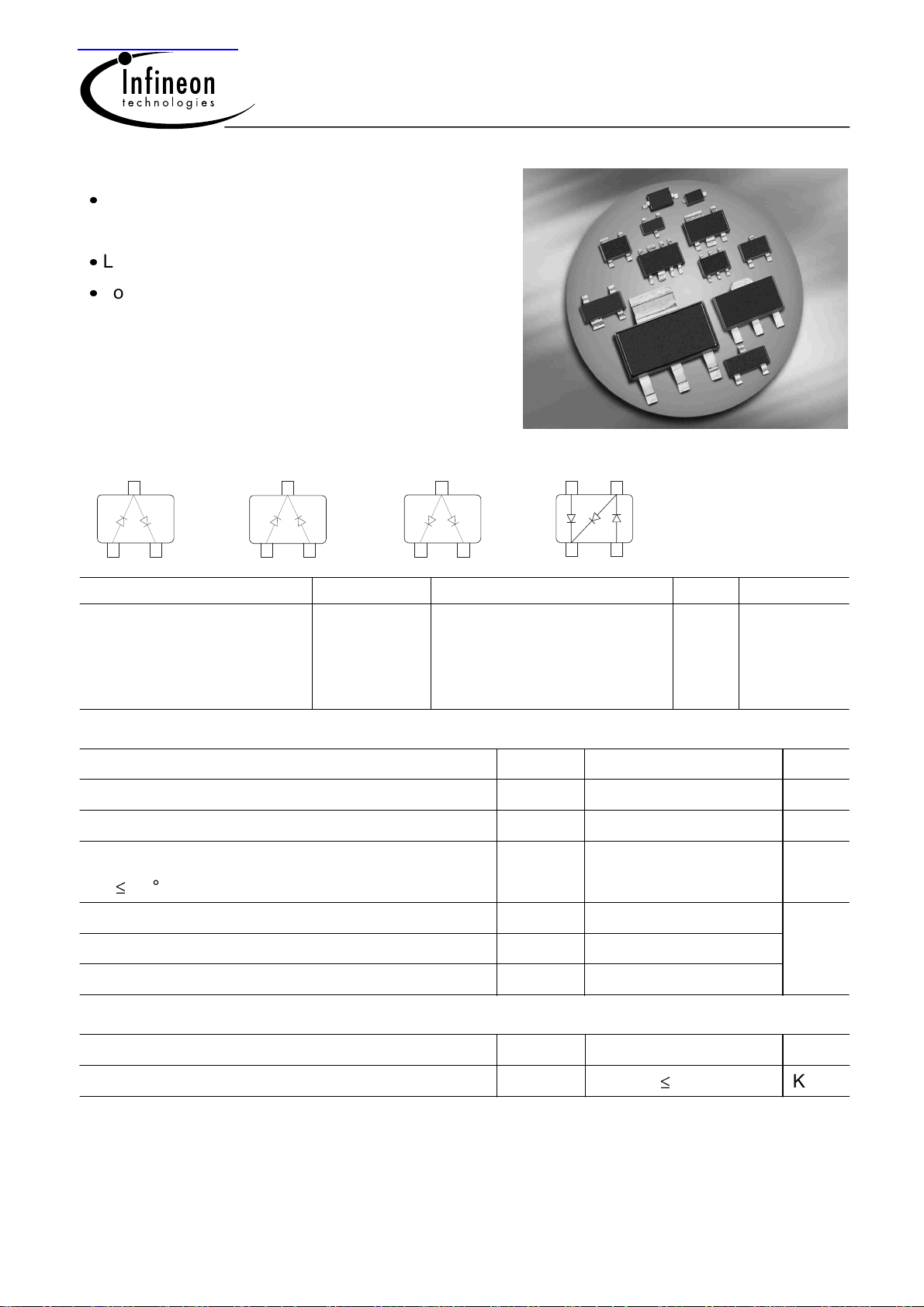
Silicon PIN Diode
RF switch, RF attenuator for frequencies
above 10 MHz
Low distortion faktor
Long-term stability of electrical characteristics
BAR14-1 BAR15-1 BAR61BAR16-1
3
D1
D2
1
2
3
D2
D1
1
2
3
D2
D1
1
2
Type Package Configuration L
BAR14-1
BAR15-1
BAR16-1
BAR61
SOT23
SOT23
SOT23
SOT143
series
common cathode
common anode
PI element
4 3
D1
D2
D3
21
(nH) Marking
S
1.8
1.8
1.8
2
L7s
L8s
L9s
61s
Maximum Ratings at TA = 25°C, unless otherwise specified
Parameter Symbol Value Unit
Diode reverse voltage V
Forward current I
Total power dissipation
65°C
T
S
P
Junction temperature T
Operating temperature range T
R
F
tot
j
op
100 V
140 mA
250 mW
150 °C
-55 ... 125
Storage temperature T
Thermal Resistance
Parameter
Junction - soldering point
1
For calculation of R
thJA
1)
please refer to Application Note Thermal Resistance
1
stg
-55 ... 150
Symbol Value Unit
R
thJS
340
K/W
Dec-20-2002
BAR14-1 / BAR15-1 / BAR16-1 / BAR61...
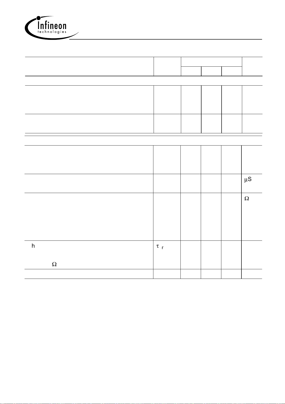
Electrical Characteristics at TA = 25°C, unless otherwise specified
Parameter Symbol Values Unit
min. typ. max.
DC Characteristics
Reverse current
V
= 50 V
R
V
= 100 V
R
Forward voltage
I
= 100 mA
F
AC Characteristics
Diode capacitance
V
= 0 V, f = 100 MHz
R
V
= 50 V, f = 1 MHz
R
Zero bias conductance
V
= 0 V, f = 100 MHz
R
Forward resistance
I
= 0.01 mA, f = 100 MHz
F
I
= 0.1 mA, f = 100 MHz
F
I
= 1 mA, f = 100 MHz
F
I
= 10 mA, f = 100 MHz
F
C
g
r
I
V
R
-
-
F
T
- 1.05 1.25 V
-
-
P
f
- 50 -
-
-
-
-
-
-
0.2
0.25
2800
380
45
7
100
1000
-
0.5
-
-
-
-
nA
pF
S
Charge carrier life time
I
= 10 mA, IR = 6 mA, measured at IR = 3 mA,
F
R
= 100
L
I-region width W
2
rr
I
700 1000 - ns
- 146 - µm
Dec-20-2002

BAR14-1 / BAR15-1 / BAR16-1 / BAR61...
Diode capacitance CT = (VR)
f = Parameter
1.0
C
T
pF
0.5
f = 1
0.0
0
10 20 30 40 V 50
Forward resistance rf = (IF)
f = 100MHz
EHD07067BAR 14-1...16-1
r
4
10
f
Ω
3
10
2
10
MHz
1
= 100f
MHz
V
R
10
0
10
-2 2
10
10
-1
10
0
10
EHD07066BAR 14-1...16-1
1
10mA
Ι
F
Forward current IF = (VF)
T
= 25°C
A
2
10
Ι
F
mA
1
10
-40 ˚CT
=
10
10
10
A
0
-1
-2
0.0
25
85
150
˚C
˚C
˚C
0.5 1.0 V 1.5
Forward current IF = (TS)
BAR14-1, BAR15-1, BAR16-1
EHD07065BAR 14-1...16-1
V
F
160
mA
120
100
F
I
80
60
40
20
0
0 15 30 45 60 75 90 105 120
°C
150
T
S
3
Dec-20-2002

BAR14-1 / BAR15-1 / BAR16-1 / BAR61...
Application circuit for attenuation networks with diode BAR61
50 k
Ω
+12 V
Input
1 nF
1 k
Ω
BAR 61
1 nF1 nF
Ω
5.6 k 4.7 k
1 k
Ω
Ω
1 nF
1 nF
BC 238
1 nF
V
Reg.
1 nF
1.8 k
12 k
Ω
2.2 k
Ω
1 nF
Output
Ω
EHM07026
4
Dec-20-2002
 Loading...