

Page 1
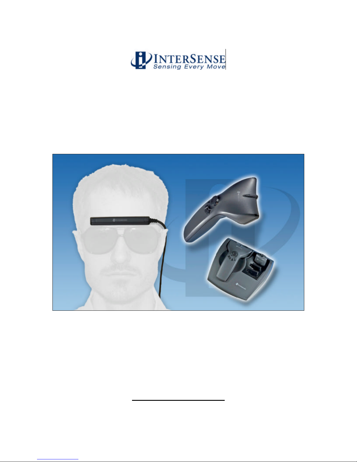
User Guide
IS-900 SimTracker & VETracker with
MicroTraxTM Devices
Phone +1 781 541 6330 • Fax +1 781 541 6329
2007 InterSense, Inc.
36 Crosby Drive, Suite 150
Bedford, MA 01730
www.intersense.com
Doc. No. 072-00092-000B Rev. 2.1
Page 2

User Guide for the IS-900 SimTracker & VETracker
Firmware 4.20 and higher
DLL Version 3.75 and higher
Contacting InterSense
Please contact us if you need assistance.
InterSense, Inc.
36 Crosby Drive
Suite 150
Bedford, Massachusetts 01730
USA
Telephone: +1 781 541 6330 email: [email protected]
Fax: +1 781 541 6329 Internet: www.intersense.com
Technical Support: +1 781 541 7624 email: [email protected]
Sales: +1 781 541 7618 email: [email protected]
Patents
The label below identifies the protection granted by the Government of the United States
to InterSense for its products:
5645077, 5807284, 6162191, 6176837, 6314055, 6361507,
6409687, 6474159,6681629, 6757068, 6786877, 6922632,
700469 and Patents Pending
Trademarks
InterSense™, InertiaCube™, InertiaCube2™ SoniDisc™, SoniStrip™, SoniFrame™,
SoniPod™ IS-900™, VETracker™, SimTracker™, ISDEMO™, GEOS™, PULSAR™,
CONSTELLATION™, MicroTrax™ are trademarks of InterSense Inc. All other
trademarks are the property of their respective owners.
Copyright 2007
InterSense, Inc.
U.S. Patents
IS-900 User Guide Page 2 of 159
Page 3
Warnings and Precautionary Statements
Any changes or modifications to the IS-900 SimTracker/VETracker,
MicroTrax Tracking Devices and other components of the IS-900 System
not expressly approved by InterSense will void the warranty and any
regulatory compliance issued for the system. This could also void the
user’s authority to operate the equipment.
Wand and Head tracker microphones are susceptible to ESD and may
require power cycling to recover from communication failure.
Do not drop or otherwise shock the tracking devices for they can be
permanently damaged.
Do not bend, twist, pull strongly or tamper in any way with any part of the
cabling.
Take care to avoid electric shocks. Do not plug-in or unplug the power
cable with wet hands.
Please see Appendix C for Health and Safety warnings and guidelines
Wireless Devices
This device contains a Lithium Ion battery that should only be used with the following warnings
and precautions.
• Avoid short circuits
• Do not dispose of the battery in fire
• Do not heat the batteries above 60°C
• Do not solder directly to the batteries
• Do not charge above 4.2V
• Do not charge below 0°C or above 45°C
• Do not discharge below 2.7V
• Do not discharge below 20°C or above 60°C
• Do not insert the batteries in reverse polarity
IS-900 User Guide Page 3 of 159
Page 4

Warning: Fire, Explosion, and Severe Burn Hazard
IS-900 User Guide Page 4 of 159
Page 5
Equipment Design:
• To avoid damage to the battery pack, make sure that the battery pack is positioned away
from heat sources in the equipment.
• If the battery pack is designed into other equipment, use caution to strictly avoid designing
airtight battery compartments.
When using the battery
Misusing the battery may cause the battery to get hot, explode, or ignite and
cause serious injury. Be sure to follow the safety rules listed below:
v Do not place the battery in fire or heat the battery.
v Do not pierce the battery with nails, strike the battery with a hammer, step
on the battery, or otherwise subject it to strong impacts or shocks.
v Do not expose the battery to water or salt water or allow the battery to get
wet.
Do not disassemble or modify the battery. The battery contains safety and
protection devices, which, if damaged, may cause the battery to generate heat,
explode or ignite.
Do not place the battery on or near fires, stoves, or other high-temperature
locations. Do not place the battery in direct sunshine, or store the battery
inside cars in hot weather. Doing so may cause the battery to generate heat,
explode, or ignite. Using the battery in this manner may also result in the loss
of performance and shortened life expectancy.
When the battery will no longer hold a charge, contact InterSense for servicing
options. Do not exchange with any other battery.
Immediately discontinue use of the battery if, while using, charging or storing
the battery the battery emits an unusual smell, feels hot, changes color,
changes shape or appears abnormal in any other way. Contact InterSense if
any of these problems have been observed.
Do not place the batteries in microwave ovens, high-pressure containers, or on
induction cookware.
In the event that the battery leaks and fluid gets into one’s eye, do not rub the
eye. Rinse well with water and immediately seek medical care. If left untreated
the battery fluid could cause damage to the eye.
IS-900 User Guide Page 5 of 159
Page 6
While charging the battery
Follow the rules listed below while charging the battery. Failure to do so may
cause the battery to become hot, explode, or ignite and cause serious injury.
• When charging the battery only InterSense’s charging station (ISC-
900MW-CRA*) or individual device charger (099-00076-0000)
Note: * means that the suffix is U, E or K depending on voltage requirements
of your country.
• Do not place the batteries in or near fire, or into direct sunlight. When the
battery becomes hot, the built in safety equipment is activated, preventing
the battery from charging further. Over-heating the battery can destroy the
safety equipment and can cause additional heating, breaking or ignition of
the battery.
Do not continue charging the battery if it does not recharge within the specified
charging time. Doing so may cause the battery to become hot, explode or
ignite.
The temperature range over which the battery can be charged is 0 degrees
Celsius to 45 degrees Celsius. Charging the battery at temperatures outside
of this range may cause the battery to become hot or to break. Charging the
battery outside this temperature range may also harm the performance of the
battery or reduce the battery’s life expectancy.
When discharging the battery
Do not discharge the battery using any devices except for the specified device.
When the battery is used in devices aside from the specified device, it may
damage the performance of the battery or reduce its life expectancy, and if the
device causes an abnormal current to flow, it may cause the battery to become
hot, explode or ignite and cause serious injury.
The temperature range over which the battery can be discharged is –20
degrees Celsius to 60 degrees Celsius. Use of the battery outside of this
temperature range may damage the performance of the battery or may reduce
its life expectancy.
General Warnings & Precautionary Statements
Do not drop or otherwise shock the tracking devices for they can be
permanently damaged.
Do not plug in any devices while the electrical power is applied.
Any changes or modifications to the IS-900 not expressly approved by
InterSense will void the warranty and any regulatory compliance issued for the
system.
IS-900 User Guide Page 6 of 159
Page 7
Do not bend, twist, pull strongly or tamper in any way with any part of the
IS-900 cabling.
Take care to avoid electric shocks. Do not plug-in or unplug the power cable
with wet hands.
During normal operation, the user should not make contact with the metal
surfaces, including the microphone housings and the connector hood, of the
tracking stations. Such contact could result in invalid data or a tracker reset.
Please see the section titled Health and Safety Warnings and Guidelines
Radio System Information
This device contains a commercially available 2.4 GHz non-frequency hopping wireless data
communication link.
The wireless link is intended for use in normal commercial applications. Applications requiring
extended temperature range or unusual environmental requirements such as military, medical
life-support or life-sustaining equipment are specifically not recommended without additional
testing for such applications.
The following devices:
• IS-900 MicroTrax Wireless Transmitter (part number 100-91000-EWTX)
These devices with their antenna comply with FCC’s RF radiation exposure
limits set forth for an uncontrolled environment. To maintain compliance,
it must not be co-located or operating in conjunction with any other
antenna or transmitter.
Complies with Part 15 of the FCC Rules. Operation is subject to the following two conditions:
1. These devices may not cause harmful interference
2. These devices must accept any interference received, including interference that may
cause undesired operation.
The following devices:
• IS-900 MicroTrax Wireless Wand (part number 100-9100-EWWD)
• IS-900 16 Channel Receiver (part number 100-IS9MW-RX16)
IS-900 User Guide Page 7 of 159
Page 8

This device complies with FCC’s RF radiation exposure limits set forth for
an uncontrolled environment. It should be installed and operated such that;
a minimum separation distance of 20cm is maintained between the radiator
(antenna) & user’s/nearby people’s body at all times. This device must not
be co-located or operating in conjunction with any other antenna or
transmitter.
Comply with Part 15 of the FCC Rules. Operation is subject to the following two conditions:
3. These devices may not cause harmful interference
4. These devices must accept any interference received, including interference that may
cause undesired operation.
IS-900 User Guide Page 8 of 159
Page 9

Table of Contents
1. System Description .............................................................................................................12
1.1. IS-900 Configuration.....................................................................................................13
1.2. IS-900 SimTracker Components ..................................................................................15
1.3. IS-900 VETracker Components....................................................................................16
1.4. IS-900 SimTracker & VETracker Processor.................................................................17
1.5. SoniStrips, SoniFrame SoniWing Constellation™ & SoniPods acoustic pulse
transmitters.................................................................................................................................17
1.6. Acoustic Constellation Mounting Considerations .........................................................19
1.6.1. SoniFrame & SoniWing Fixed Constellations ..........................................................19
1.6.2. SoniPods..................................................................................................................20
1.7. Tracking Station Description.........................................................................................20
1.7.1. MicroTrax Wand with Joystick..................................................................................21
1.7.2. MicroTrax Head Tracker...........................................................................................22
1.7.3. MicroTrax Docking Station.......................................................................................23
1.7.4. Wireless MicroTrax Modules....................................................................................24
1.7.5. OEM Tracking Devices.............................................................................................24
1.8. IS-900 Cables, Connectors, Adaptors, Power Boosters and Wireless Radios............25
1.8.1. Wired System...........................................................................................................25
1.8.2. Wireless System.......................................................................................................28
1.8.3. All Systems...............................................................................................................29
1.9. IS-900 Support CD .......................................................................................................31
2. Specifications......................................................................................................................32
2.1. Performance Specifications..........................................................................................32
2.2. Physical Specifications.................................................................................................33
2.3. Environmental Specifications........................................................................................33
3. Installation and Set-up.........................................................................................................34
3.1. InterSense Coordinate Reference Frame.....................................................................35
3.2. Hardware Set-up...........................................................................................................36
3.3. Installation of SoniStrips...............................................................................................37
3.3.1. SoniStrip Mounting for Ceiling Installations..............................................................40
3.3.2. SoniStrip Mounting for Power Wall Installations ......................................................41
3.3.3. SoniStrip Mounting for CAVE-like Installations........................................................42
3.3.4. SoniFrame and SoniWing ........................................................................................43
3.4. Measurement and Calibration of SoniStrips.................................................................43
3.5. Connections with IS-900 Processor .............................................................................46
3.6. Wireless MicroTrax Setup.............................................................................................47
3.7. Loading the Constellation File......................................................................................52
3.8. Using Wireless MicroTrax Devices...............................................................................59
8. Interface Communication Protocol......................................................................................61
8.1. Commands Sent from the Host to the Tracker.............................................................61
8.2. Standard Fastrak™ Interface Commands...................................................................61
8.3. Fastrak™ Commands Implemented for Compatibility..................................................69
8.4. InterSense specific Commands....................................................................................69
8.4.1. System Configuration Commands............................................................................69
8.4.2. InterSense-specific Station Parameters...................................................................73
8.4.3. Station and Constellation Configuration Commands ...............................................75
8.5. Records Returned from the Tracker to the Host...........................................................77
8.5.1. Format Considerations.............................................................................................77
8.5.2. Status Record Hexadecimal Character Decoding....................................................77
8.5.3. Fastrak™ System and Data Records.......................................................................78
8.5.4. InterSense-specific Records ....................................................................................83
8.5.5. Records Specific to IS-900 Models..........................................................................85
9. LCD Status & Settings Screen............................................................................................87
IS-900 User Guide Page 9 of 159
Page 10

9.1. Overview.......................................................................................................................87
9.2. Normal Operation (Steady State).................................................................................88
9.3. Example of LCD Menu Navigation ...............................................................................91
9.4. IS-900 LCD Menu Flow Chart.......................................................................................92
10. Appendix A – Frequently Asked Questions.........................................................................93
11. Appendix B – Troubleshooting & Tips.................................................................................95
12. Appendix C - Health & Safety Warnings with Tracker Use Guidelines...............................98
13. Appendix D– Care & Maintenance ....................................................................................100
14. Appendix E – ISDEMO Reference....................................................................................101
14.1. Getting Started............................................................................................................101
14.2. File Options.................................................................................................................103
14.3. Communications Options............................................................................................104
14.4. Parameter Options......................................................................................................106
14.4.1. Wireless Configuration window..........................................................................111
14.5. Display Options...........................................................................................................113
14.6. Tool Options................................................................................................................114
14.6.1. System Errors ....................................................................................................123
14.7. Constellation Configuration Tool ................................................................................124
14.8. RF Scope....................................................................................................................137
15. Appendix F – GENLOCK Synchronization........................................................................139
15.1. Why Use GENLOCK?.................................................................................................139
15.2. Configuring the IS-900 for GENLOCK........................................................................141
16. Appendix G – Developers Instructions..............................................................................144
16.1. Introduction.................................................................................................................144
16.2. Sample Program.........................................................................................................144
16.3. Usage..........................................................................................................................145
16.4. API..............................................................................................................................146
16.5. Data Structures...........................................................................................................151
16.5.1. ISD_TRACKER_INFO_TYPE............................................................................151
16.5.2. ISD_STATION_INFO_TYPE .............................................................................153
16.5.3. ISD_STATION_STATE_TYPE ..........................................................................156
17. Appendix H – Interface Protocol Commands – Quick Reference.....................................158
IS-900 User Guide Page 10 of 159
Page 11

Table of Figures
Figure 1 - IS-900 Functional Diagram............................................................................................13
Figure 2 - IS-900 SimTracker Processor .......................................................................................17
Figure 3 - IS-900 VETracker Processor.........................................................................................17
Figure 4 - IS-900 SoniStrips...........................................................................................................17
Figure 5 - IS-900 SoniWing............................................................................................................18
Figure 6 - IS-900 SoniFrame with three 6 ft. SoniStrips Assembled and Mounted on a Ceiling...18
Figure 7 - Discrete SoniDisc Transmitter (SoniPod)......................................................................18
Figure 8 - IS-900 Tracked Stations................................................................................................20
Figure 9 - MicroTrax Wand ............................................................................................................21
Figure 10 - MicroTrax Head Tracker..............................................................................................22
Figure 11 - MicroTrax Docking Station ..........................................................................................23
Figure 12 - Wired IS-900 and MicroTrax Cables, Connectors and Adapters................................25
Figure 13 - Wireless IS-900 and MicroTrax Cables, Connectors and Adapters............................28
Figure 14 - SoniStrip Power Booster (Optional).............................................................................30
Figure 15 - InterSense Coordinate Reference Frame ...................................................................35
Figure 16 - Unit Normal Vector Definition for Ceiling Installed SoniStrip.......................................38
Figure 17 - Tracking Coverage with Two SoniStrips .....................................................................38
Figure 18 - Immersive Room Ceiling Mounting (top down view)...................................................40
Figure 19 - Power Wall Perimeter mounting (front forward view)..................................................41
Figure 20 - CAVE-like Installation (top down view)........................................................................42
Figure 21 - External Power Booster for SoniStrips........................................................................47
Figure 22 - Configuration Script Menu for loading SoniStrip Constellation array file.....................53
Figure 23 - Configuration Script File Menu....................................................................................53
Figure 24 - Sending Configuration Script to Tracker .....................................................................54
Figure 25 - Constellation Tool Selection........................................................................................54
Figure 26 - Checking installed SoniStrip Constellation Array........................................................55
Figure 27 - ISDEMO Constellation Tool Screen for Ceiling Mount Power Wall Applications........55
Figure 28 - ISDEMO Constellation Tool Screen for Wall Mount Power Wall Applications............56
Figure 29 - ISDEMO Constellation Tool Screen for CAVE-like Applications.................................56
Figure 30 - ISDEMO Constellation Tool Screen with Tracking Device..........................................57
Figure 31 - Tracking Status Display on IS-900 LCD Panel............................................................57
Figure 32 - Saving All Configuration Settings to IS-900 Processor...............................................58
Figure 33 - Locking Configuration Settings in IS-900 Processor...................................................58
Figure 34 - IS-900 LCD Status & Settings Screen.........................................................................87
Figure 35 - LCD Panel in Normal Display Mode (Tracking One Station) ......................................88
Figure 36 - Status Display of Additional Tracking Stations............................................................88
Figure 37 - Rejected Measurement Status for Tracking Station 1.................................................89
Figure 38 - Communication Integrity Status for a Wired Tracking Station 1..................................90
Figure 39 - Tracking Quality Status for a Wired Tracking Station 1 ..............................................90
Figure 40 - IS-900 LCD Menu Flow Chart .....................................................................................92
Figure 41 - Frequency Range for Each of the 16 Channels........................................................137
Figure 42 – Timing Diagram: IS-900 Interfaced to PC with 60 Hz Display Refresh....................139
Figure 43 - Timing Diagram: IS-900 Adjusted with Proper Phase for 60 Hz Display Refresh....140
Figure 44 - Back Panel of IS-900, SYNC IN is External GENLOCK Input ..................................141
IS-900 User Guide Page 11 of 159
Page 12

1. System Description
The IS-900 product family delivers precision motion tracking technology for simulators, training,
virtual, and immersive display systems. The IS-900, designed for dedicated, precision 6 degree
of freedom (6-DOF) motion tracking for both small tracking area simulators and large area virtual
environments.
This manual covers two IS-900 product configurations—the IS-900 SimTracker (Simulation
Tracker) and the IS-900 VETracker (Virtual Environment Tracker). The SimTracker is ideal for
smaller 3D environments such as cockpit or desktop simulators while the VETracker is ideal for
large immersive 3D environments. This manual also covers the wireless MicroTraxTM devices for
the IS-900 System. Please note that OEM configurations are also available.
The IS-900 product design provides a great deal of flexibility for custom or OEM configurations.
While the specific configuration of your IS-900 system may vary from the SimTracker and
VETracker standard products, the fundamental set-up, calibration, and operation principles
remain the same as described in this manual.
The system operates on hybrid technology combining inertial and ultrasonic tracking. The output
of the miniature inertial components (both accelerometers and gyros found in each tracking
device) determines position and orientation of the tracking stations. Using advanced Kalman
filters, constant drift correction is applied by fusing the output of the inertial sensors with range
measurements obtained from the ultrasonic components. The result is full 6-DOF data that is
very smooth, precise, and free from jitter.
Advantages of the IS-900 technology include:
• Low cost system utilizes IS-900 technology for small area tracking
• Immune to metallic, most acoustic, and optical interference
• Sensor design eliminates acoustic transmitter “line of sight” blockage
• Consistent accuracy over entire tracking volume
• Factory calibration configurations available for accurate position mapping of acoustic
transmitters
• Superior motion prediction algorithms
• Integration of tracking devices into OEM applications
Wireless MicroTraxTM Devices
The MicroTraxTM wireless tracker modules for the IS-900 allow for untethered 6 degree of
freedom (6-DOF) tracking. They can be used along side wired tracking devices and the devices
themselves can be converted from wired to wireless by using different cable adapters.
The radio/battery modules (Wireless Transmitter Modules) have lithium polymer batteries with
enough capacity to provide 6-8 hours of continuous use and can be fully recharged in 3 hours.
The Transmitter Modules have a processor that detects if the unit has not moved within 10
minutes and will automatically stop tracking and turn itself off to extend the battery life / tracking
time. The device monitors the battery voltage and has an indicator that will flash to indicate a low
battery condition at approximately 1 hour of tracking left before the unit must be recharged. The
batteries can be recharged about 500 times before the length of time the charge lasts starts to
decline. The batteries are field replaceable when charge cycle deterioration renders them
ineffective.
IS-900 User Guide Page 12 of 159
Page 13
In June 2007, we introduced the new MicroTraxTM wireless devices for the IS-900 System. These
PORT1
RS-232 Port
HOST MicroTrax
IS-900 SimTracker or IS
-
900 VETracker Processor
MicroTrax
AC Power & Switch
LCD Displa
y with
Buttons
Ethernet Port
ETH
PORT2 PORT3 PORT4 PORT5 PORT6 PORT7 PORT8
MicroTrax Tracker and SoniStrip Ports*
PORT1 PORT2 PORT3 PORT4 PORT5 PORT6 PORT7 PORT8
LED Display of Active Ports
ENTER F1 F2
*NOTE: IS
-
900 SimTracker Supp
orts only five Tracker/SoniStrip Ports
SoniStrip
SoniStrip
SoniStrip
Processor
InterSense IS
-
900 SimTracker & VETracker
Functional Block Diagram
devices include a Head Tracker, Wand and a new Docking Station. The docking station is a new
component in our offering that allows you to recharge your wireless devices and spare batteries
in-situ via contacts while they rest in the cradle. The MicroTrax devices use a 2.4 GHz nonfrequency hopping spread spectrum radio module that allows up to 16 different channel
selections.
1.1. IS-900 Configuration
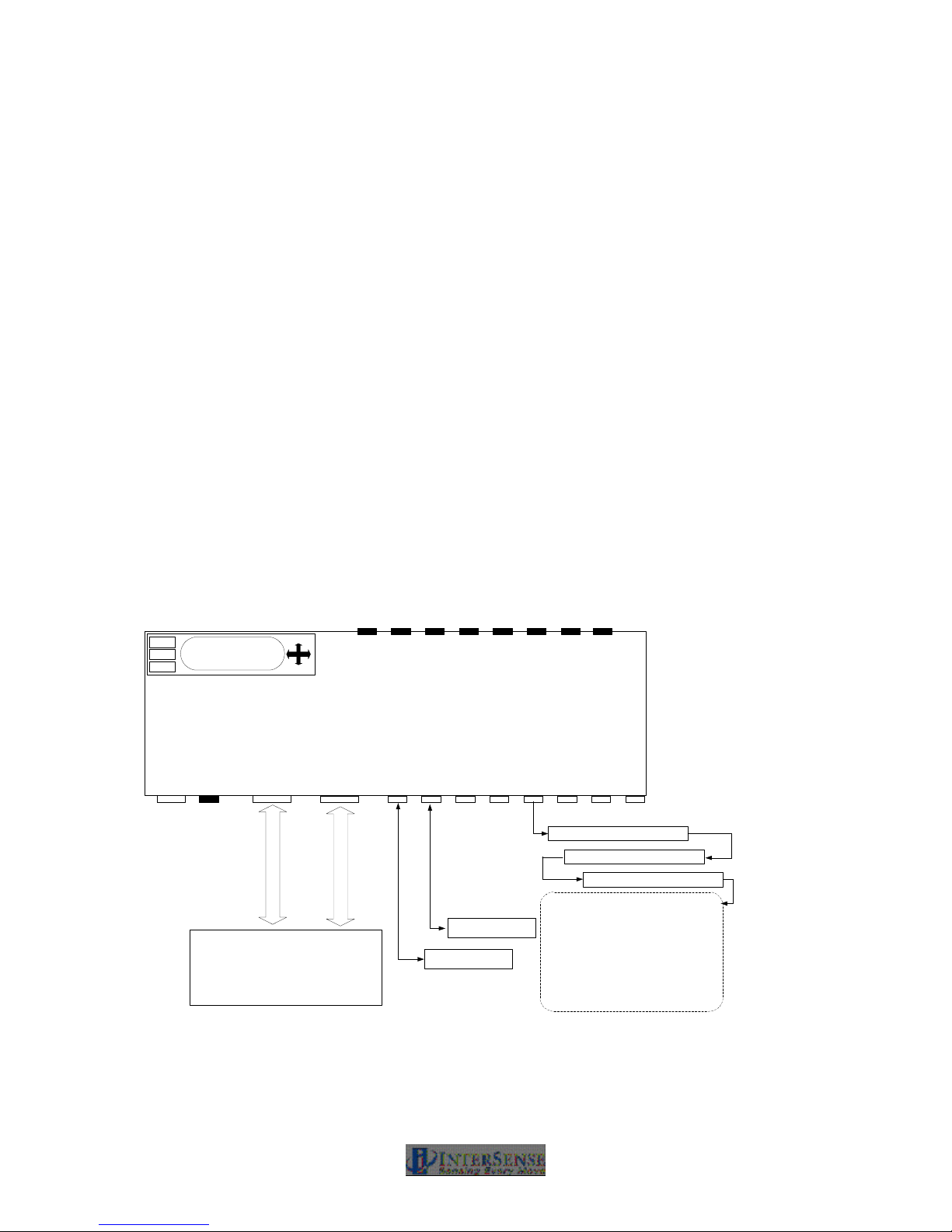
As shown in the block diagram in Figure 1, the IS-900 offers a wide range of tracking options.
InterSense’s SensorFusion code for calculating the full 6-DOF tracking solution is performed by
the dedicated IS-900 processor. The MicroTrax tracking devices and SoniStrips plug into the
serial interface ports and the IS-900 processor interfaces directly to a host computer via RS-232
serial port or Ethernet.
The IS-900 SimTracker supports a maximum of 4 MicroTrax devices and 12 SoniStrips (36
SoniDisc ultrasonic emitters). The IS-900 VETracker supports a maximum of 7 MicroTrax
devices and up to 42 SoniStrips (126 SoniDiscs) on an interface port. The VETracker can also
be configured to support 7 MicroTrax devices and up to 84 SoniStrips split between two interface
ports (42 SoniStrips or 126 SoniDiscs per port).
Host Computer or Graphics
Figure 1 - IS-900 Functional Diagram
IS-900 User Guide Page 13 of 159
...
Device
Device
- IS-900 SimTracker supports up to 12
SoniStrips (36 SoniDiscs)
- IS-900 VETracker supports up to 42
SoniStrips (126 SoniDiscs per port) & up to
84 SoniStrips per system (252 SoniDiscs)
- IS-900 VETracker requires an in-line Power
Booster for every 12 SoniStrips.
Page 14

The IS-900 SimTracker and VETracker works with all of InterSense’s standard wired & wireless
MicroTrax devices (Head Tracker and Wand) plus several specialized devices developed for
OEM applications (Helmet Tracker, NVIS Virtual Binoculars & HMD, plus others).
Note that some early versions of InterSense’s devices are not compatible with the SimTracker &
VETracker components. Please check with InterSense Technical Support
([email protected]) to see if upgrades are required if you plan to use previously
purchased devices with the IS-900 SimTracker or VETracker system.
IS-900 User Guide Page 14 of 159
Page 15

1.2. IS-900 SimTracker Components
The IS-900 SimTracker System ships in a standard configuration package with an IS-900
Processor, four SoniStrips, two MicroTrax Tracking Devices, the IS-900 Product CD (version 4.23
or higher), and all the required interface cables.
IS900 SimTracker Wireless 4R36 System Qty ISC-900MW-SIM(U, E, or K)*
IS900-1U 5Port Serial Base Unit 1 100-IS900-PCU5
MicroTrax Head Tracker with 3' Cable 1 100-91003-AWHT
IS-900,MicroTrax Transmitter Wireless 1 100-91000-EWTX
MicroTrax Wireless Wand 1 100-91000-EWWD
IS900 RS422 16 Channel Receiver 2 100-IS9MW-RX16
IS900 Acoustic Timing Adjuster 1 100-IS9MW-ATA1
IS-900,MicroTrax TTL-RS422 Dongle 1 100-91000-AWDG
MicroTrax Charging Station 1 100-91000-EWBS
Power Cord 1 078-2COND-XX06*
Rev3 10 to 10 pin RJ48 1 Foot 1 078-00088-0001
Cable Null Modem FD9-FD9 1 078-00001-0000
Battery, Lithium Polymer,3.7V,550mA-Hr 4 060-LPEZP-K550
Power Cord 18AWG, 9foot 1 078-00003-XX09*
6 Foot SoniStrip Rev.3 4 100-SRAL3-6000
Rev3 10 to 10 pin RJ48 30 Foot 2 078-00088-0030
Rev3 10 to 10 pin RJ48 4 Foot 3 078-00088-0004
Ceiling Clip, 1/4-20 x 5/8 8 068-HDP00-0000
45 deg Angle Bracket 8 082-00069-0000
Screw,1/4-20x1/2,PH,Pan,black 8 092-P1420-BP08
IS900 SimTracker WWIIRREEDD 4R36 System Qty ISC-900M0-SIM(U, E, or K)*
IS900-1U 5Port Serial Base Unit 1 100-IS900-PCU5
MicroTrax Head Tracker with 3' Cable 1 100-91003-AWHT
IS-900,MicroTrax TTL-RS422 Dongle 1 100-91000-AWDG
MicroTrax Wired Wand with 12' Cable 1 100-91012-AWWD
Mini/uTrax 232 TO 422 SDP Dongle 1 100-SDPDL-0001
Rev3 10 to 10 pin RJ48 30 Foot 3 078-00088-0030
Cable Null Modem FD9-FD9 1 078-00001-0000
Power Cord 18AWG, 9foot 1 078-00003-XX09*
6 Foot SoniStrip Rev.3 4 100-SRAL3-6000
Rev3 10 to 10 pin RJ48 4 Foot 3 078-00088-0004
Ceiling Clip, 1/4-20 x 5/8 8 068-HDP00-0000
45 deg Angle Bracket 8 082-00069-0000
Screw,1/4-20x1/2,PH,Pan,black 8 092-P1420-BP08
*Suffix or “XX” depends on geography
IS-900 User Guide Page 15 of 159
Page 16

1.3. IS-900 VETracker Components
The IS-900 VETracker System ships in a standard configuration package with an IS-900
Processor, six SoniStrips, two MicroTrax Tracking Devices, the IS-900 Product CD, and all the
required interface cables.
IS900 VETracker WWIIRREELLEESSSS 6R36 System Qty ISC-900MW-VET(U, E, or K)*
IS900-1U 8Port Serial Base Unit 1 100-IS900-PCU8
MicroTrax Head Tracker with 3' Cable 1 100-91003-AWHT
IS-900,MicroTrax Transmitter Wireless 1 100-91000-EWTX
MicroTrax Wireless Wand 1 100-91000-EWWD
IS900 RS422 16 Channel Receiver 2 100-IS9MW-RX16
IS900 Acoustic Timing Adjuster 1 100-IS9MW-ATA1
IS-900,MicroTrax TTL-RS422 Dongle 1 100-91000-AWDG
MicroTrax Charging Station 1 100-91000-EWBS
Power Cord 1 078-2COND-XX06*
Rev3 10 to 10 pin RJ48 1 Foot 1 078-00088-0001
Cable Null Modem FD9-FD9 1 078-00001-0000
Battery, Lithium Polymer,3.7V,550mA-Hr 4 060-LPEZP-K550
Power Cord 18AWG, 9foot 1 078-00003-XX09*
6 Foot SoniStrip Rev.3 6 100-SRAL3-6000
Rev3 10 to 10 pin RJ48 30 Foot 2 078-00088-0030
Rev3 10 to 10 pin RJ48 4 Foot 5 078-00088-0004
Ceiling Clip, 1/4-20 x 5/8 12 068-HDP00-0000
45 deg Angle Bracket 12 082-00069-0000
Screw,1/4-20x1/2,PH,Pan,black 12 092-P1420-BP08
IS900 VETracker Wired 6R36 System Qty ISC-900M0-VET(U, E, or K)*
IS900-1U 8Port Serial Base Unit 1 100-IS900-PCU8
MicroTrax Head Tracker with 3' Cable 1 100-91003-AWHT
IS-900,MicroTrax TTL-RS422 Dongle 1 100-91000-AWDG
MicroTrax Wired Wand with 12' Cable 1 100-91012-AWWD
Mini/uTrax 232 TO 422 SDP Dongle 1 100-SDPDL-0001
Rev3 10 to 10 pin RJ48 30 Foot 3 078-00088-0030
Cable Null Modem FD9-FD9 1 078-00001-0000
Power Cord 18AWG, 9foot 1 078-00003-XX09*
6 Foot SoniStrip Rev.3 6 100-SRAL3-6000
Rev3 10 to 10 pin RJ48 4 Foot 5 078-00088-0004
Ceiling Clip, 1/4-20 x 5/8 12 068-HDP00-0000
45 deg Angle Bracket 12 082-00069-0000
Screw,1/4-20x1/2,PH,Pan,black 12 092-P1420-BP08
*Suffix or “XX” depends on geography
IS-900 User Guide Page 16 of 159
Page 17
1.4. IS-900 SimTracker & VETracker Processor
The IS-900 Processor uses specialized firmware running on a dedicated processor to control
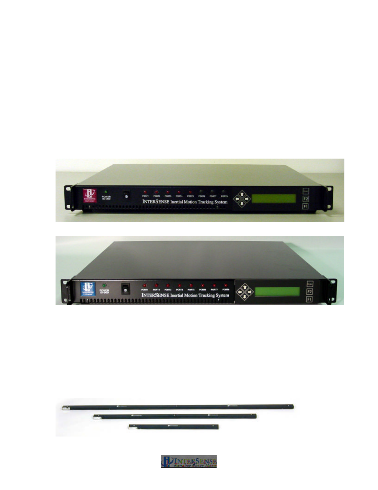
motion sensor data acquisition and then calculate tracking and related data for output over serial
or Ethernet interfaces. Shown in Figure 2, the SimTracker Processor has five front panel LEDs
which indicate active ports during normal operation. Shown in Figure 3, the VETracker
Processor has eight front panel LEDs to indicate active ports. Both processor configurations
have a front panel LCD display and selection buttons for checking and changing tracking system
parameters. The tracking devices, SoniStrip, host computer, and power connectors are accessed
from the rear panel (described in detail in Section 3).
Figure 2 - IS-900 SimTracker Processor
Figure 3 - IS-900 VETracker Processor
1.5. SoniStrips, SoniFrame SoniWing Constellation™ &
SoniPods acoustic pulse transmitters
The SoniStrips (Figure 4), SoniWing (Figure 5), SoniFrame (Figure 6) and SoniPods (Figure 7)
have ultrasonic SoniDisc transmitters that receive addressed signals from the Base Processor
Unit and transmit ultrasonic pulses in response. The acoustic transmission beam width for each
SoniDisc is adjusted for wide-angle coverage (approx. 70-degree cone angle) to maximize the
tracking area.
Figure 4 - IS-900 SoniStrips
IS-900 User Guide Page 17 of 159
Page 18
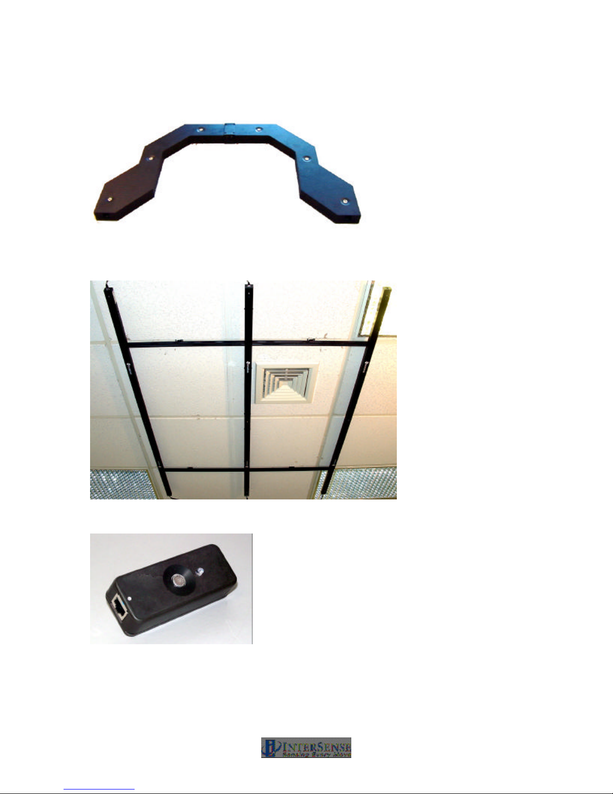
Figure 5 - IS-900 SoniWing
Figure 6 - IS-900 SoniFrame with three 6 ft. SoniStrips Assembled and Mounted on a
Ceiling
Figure 7 - Discrete SoniDisc Transmitter (SoniPod)
The IS-900 uses an acoustic time-of-flight (TOF) ranging system to prevent position and
orientation drift. For maximum accuracy and resolution, acoustic range measurements are made
with unidirectional TOF measurements from the SoniStrip transmitters to the Tracked Stations.
IS-900 User Guide Page 18 of 159
Page 19

The SoniDiscs’ acoustic pulses are detected by miniature microphones integrated in the Tracked
Stations.
Details of the assembly and set up of the SoniFrame and SoniWing are found in a supplemental
manual in your IS-900 product CD.
1.6. Acoustic Constellation Mounting Considerations
The IS-900 product family offers a wide range of options to meet the needs of many different
tracking environments.
SoniStrips are normally mounted from the ceiling over the desired tracking workspace. To
increase the flexibility of this system, the IS-900 has been designed with different sized SoniStrips
for mounting in a variety of immersive environments (CAVE®/CAVE-like, Reality Center, iCenter,
ImmersaDesk, ReaCTor, PowerWall, CUBE, etc.). The user is able to position SoniStrips in most
environments, including confined spaces such as virtual workbenches, automobiles, and cockpit
simulators. Once installed, the user must calibrate the SoniStrip Constellation by measuring the
Cartesian x, y, z coordinates of each SoniStrip and enter this information using the Constellation
Configuration Utility Program provided with the system. A trained technical representative should
perform the process of calibration. InterSense provides installation and training upon request.
Adjusting the tracking volume is easily accomplished by selecting the appropriate ultrasonic
Constellation components. Options include different sized SoniStrips, discrete SoniPods and precalibrated SoniFrame or SoniWing structures.
1.6.1. SoniFrame & SoniWing Fixed Constellations
The fixed frame SoniFrame assembly provides up to a 2 x 2 x 3 meter tracking volume with no
special sighting or calibration of the SoniStrips. The three SoniStrips easily mount to the
SoniFrame assembly to produce a repeatable rigid structure that is portable and convenient to
use. The SoniFrame provides a quick and convenient method for setting the IS-900’s tracking
area that does not require optical sighting for calibration.
The aluminum frame is made from a standard extrusion product that when assembled properly
will provide an accurate mounting platform for InterSense’s ultrasonic SoniStrip and SoniDisc
tracking referencing components.
The design of the Fixed Frame provides mechanical mounting options for all InterSense
SoniStrips in all lengths (2-foot, 4-foot and 6-foot) and combinations. Figure 6 shows a typical
SoniFrame fully assembled and ceiling mounted with three 6 ft. SoniStrips.
Interconnect bars are available to assemble multiple SoniFrames together as one structure.
NOTE: When using multiple SoniFrames connected with InterSense’s interconnect bars, the fully
assembled & interconnected frames must be mounted to a rigid structure (i.e. a lighting grid or
ceiling structure). Furthermore, the mounted SoniFrames must be leveled and co-planer in order
to achieve accurate tracking.
The SoniWing is a smaller fixed frame assembly ideal for cockpit simulators or desktop tracking
applications. The SoniWing, like the SoniFrame, does not require special measurement or
calibration. The exact location of the SoniDiscs is measured by InterSense and included in the
ISDEMO Constellation configuration utility program provided with the system. As with
SoniFrames, multiple SoniWings can be utilized with a single system (i.e. a dual cockpit flight
simulator configuration can use two SoniWings to simultaneously track two pilot head positions).
IS-900 User Guide Page 19 of 159
Page 20
1.6.2. SoniPods
The SoniPod is a discrete SoniDisc packaged in its own enclosure with mechanical and electrical
interfaces. SoniPods provide the most flexible Constellation configuration option for closed
spaces, cockpits, or spaces that do not offer simple mounting spaces for fixed frames or
SoniStrips. Each SoniPod is connected by “daisy chain” to the next with one cable from the IS900 processor. It is highly recommended that InterSense installation engineers are consulted for
configuration, installation and calibration of an IS-900 SoniPod Constellation array.
1.7. Tracking Station Description
For InterSense motion tracking systems, a “station” is the tracked object or device, which by
industry jargon may also be called a sensor or tracker. An IS-900 tracks all stations in a 6-DOF
mode, meaning each tracked device outputs X, Y, Z position information along with a pitch, yaw
and roll orientation information. In addition, the Wand Tracking Station output joystick and button
information for use with the immersive environment software. Figure 8 summarizes InterSense’s
IS-900 Tracking Stations.
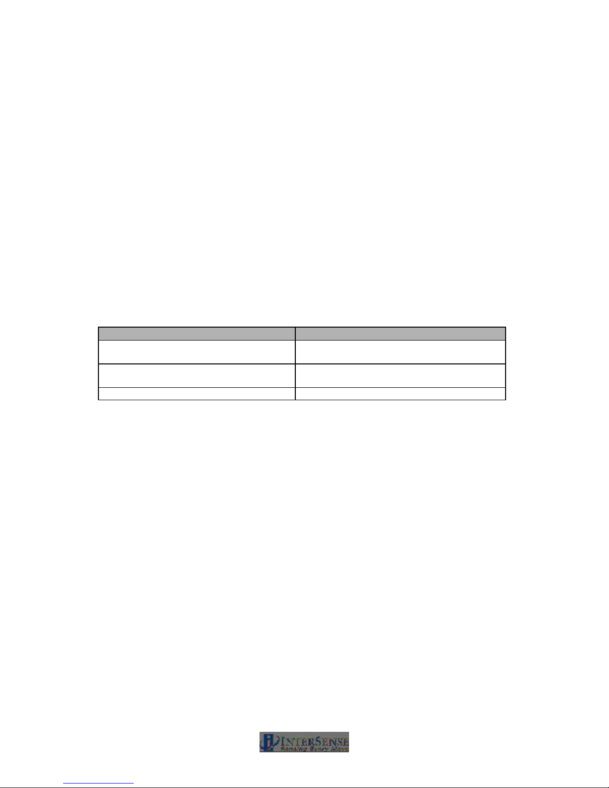
Tracked Station Function
MicroTrax Wand w/ Joystick Tracking
Station
MicroTrax Head Tracking Station Stereo glasses and Head Mounted Display
MicroTrax OEM Tracking Stations Specific to OEM application
Figure 8 - IS-900 Tracked Stations
Each tracked station sends inertia measurement unit (IMU) data (angular & acceleration rates)
with Ultrasonic Receiver Module (URM) acoustic range data for transmission to IS-900 base
processor via wired or wireless links.
InterSense provides the different types of tracked stations listed above for use in immersive
environments. All of these tracked stations use InterSense’s advanced inertial MicroTrax
technology combined with miniaturized digital acoustic position referencing components.
In addition to InterSense’s standard tracked stations, there are also new OEM devices being
delivered with some IS-900 systems that integrate the IS-900 technology into custom 3rd party
tracked stations. IS-900 systems shipped with 3rd party devices come with documentation
specific to these devices.
All of InterSense’s MicroTrax tracking devices can be configured with a wireless transmitter &
receiver for unencumbered tracking over larger areas.
The following sections summarize all of the options available from your local reseller or
InterSense.
Five button with center push button joystick
(HMD) mounted
IS-900 User Guide Page 20 of 159
Page 21
1.7.1. MicroTrax Wand with Joystick
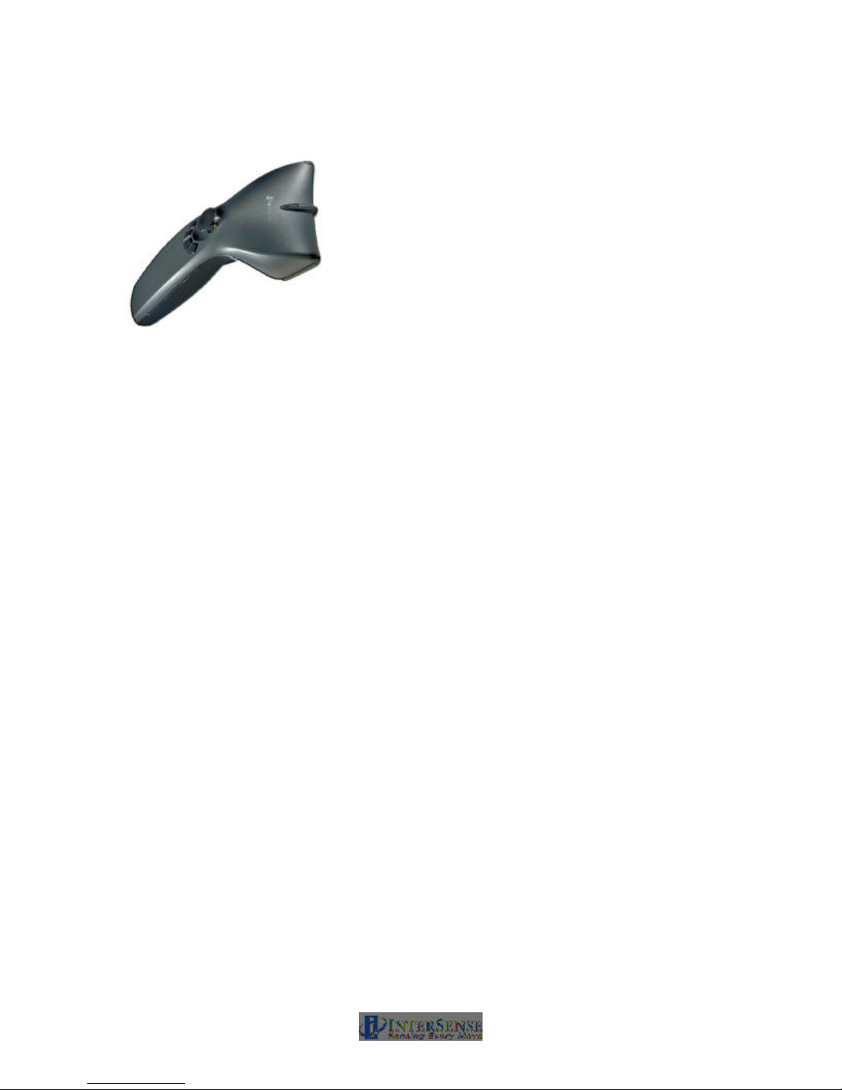
Figure 9 - MicroTrax Wand
The MicroTrax Wand with center-click Joystick (Figure 9) is a tracked device that provides a
simple and convenient way for the user to interact with virtual environments.
There are four miniature acoustic receiver microphones integrated into the MicroTrax Wand.
During operation, all four miniature microphones are sampling the ultrasonic signals. Based on
the trackers position with respect to ultrasonic Constellation array, only signals from the two best
microphones are used for combination with the inertial data and calculation of the 6-DOF output.
Each miniature receiver microphone has a reception cone angle approaching 180°. With two
pairs of microphones located on the top and bottom of the MicroTrax Wand, the wand will
consistently track over a full 360° range of motion in all axes while under the active Constellation
array. The Wand will continue to track during brief (less than 1 minute) occlusion of one of the
active pair microphones.
Each of the five buttons (four on top and one below plus sixth button on the joystick can be
accessed from the IS-900 data stream by calling the output record Data Item 22. The two axis
analog joystick provides an easy “fly-through” navigation interface used in most immersive virtual
environments. The access to joystick data comes by calling the output record Data Item 23.
The device powers on by pressing the left button for ~ 3seconds. The unit will auto-off after 10
minutes of no movement to preserve battery power. To shut the unit off, press the left button and
right button simultaneously (pressing the left button for ~ 2minutes will also power off the device).
Details of format, definition, and programming your application to use the buttons and joystick can
be found in Section 8.
IS-900 User Guide Page 21 of 159
Page 22
1.7.2. MicroTrax Head Tracker
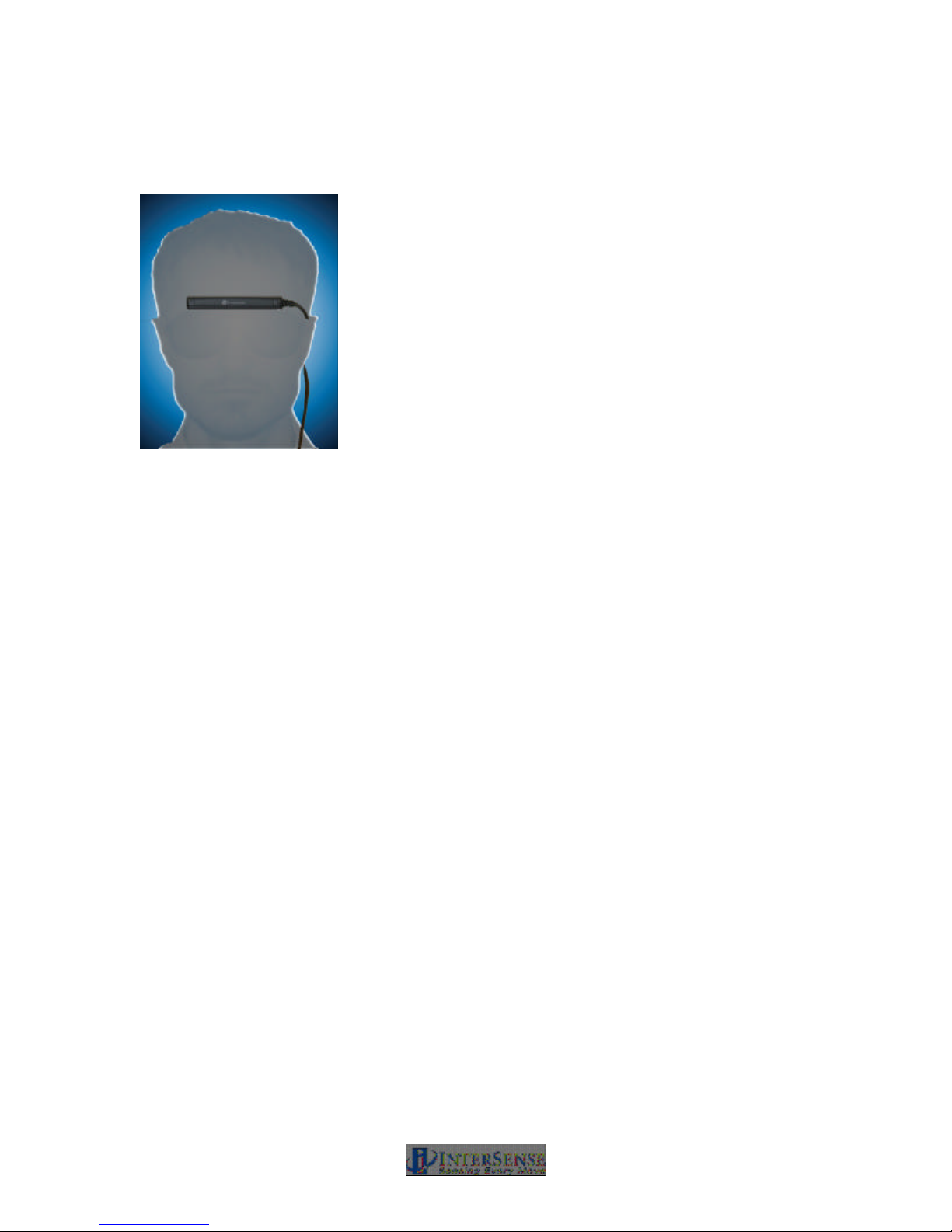
Figure 10 - MicroTrax Head Tracker
The MicroTrax Head Trackers (Figure 10) are tracked devices that provide accurate 6-DOF data
needed to give the user a correct visual viewpoint in an immersive visual environment. The
MicroTrax head tracker is suitable for use in both projected (Simulators, CAVE®s, PowerWalls,
etc…) and head worn (HMDs) application where head tracking is required.
The device powers on by pressing the button for ~ 3seconds. The unit will auto-off after 10
minutes of no movement to preserve battery power. To shut the unit off, press and hold the
button for 6 seconds.
There are two miniature acoustic receiver microphones integrated into the MicroTrax Head
Tracker. During operation, all miniature microphones are sampling the ultrasonic signals. Each
miniature receiver microphone has a reception cone angle approaching 180°.
The MicroTrax Head Tracker has the receiver microphones placed at a 45° angle off the front of
the device assuring continual tracking with all normal head positions in standard ceiling or wall
mounted Constellation arrays. The head trackers will continue to track during brief (less than 1
minute) occlusion of one of the microphones.
IS-900 User Guide Page 22 of 159
Page 23
1.7.3. MicroTrax Docking Station
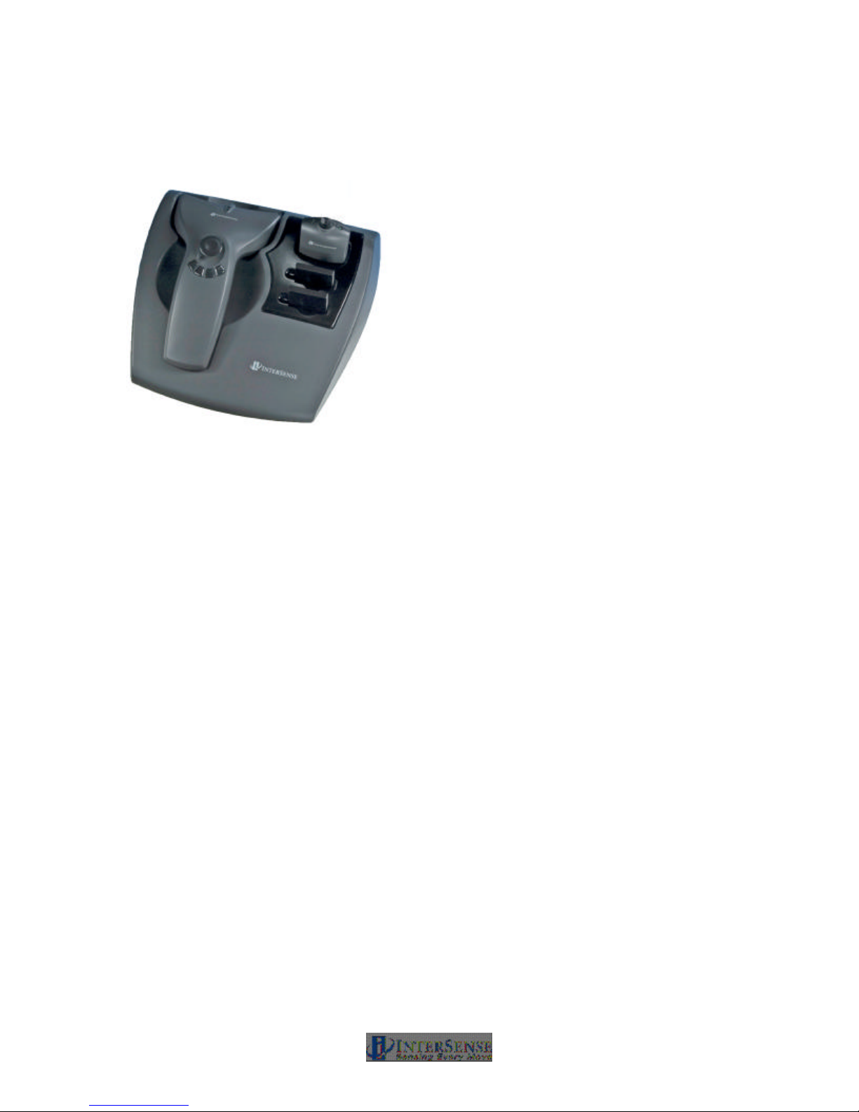
Figure 11 - MicroTrax Docking Station
The MicroTrax Docking Station (Figure 11) is an optional component that serves to hold all the
MicroTrax devices in one handy place. InterSense offers the docking station in two different
configurations:
Housing for Wired Devices
The first configuration is primarily useful for wired devices where the docking station is a simple
cradle to hold all the devices in one place.
Charging Station for Wireless Devices
The second configuration is useful for wireless devices where charging contacts are incorporated
enabling recharging in-situ. In this configuration, LEDs next to each slot indicate when the device
is in the process of charging or is completely charged. When the LED light is illuminated and the
color is:
• Orange Device is in the process of recharging
• Green Device is fully charged.
• Off Device is either not in contact (not fully seated) or the docking station is
not powered.
IS-900 User Guide Page 23 of 159
Page 24

1.7.4. Wireless MicroTrax Modules
All MicroTrax tracked stations can be operated without cabling to the IS-900 processor by using
the IS-900 Wireless Modules. The Wireless Modules have two components—a receiver
component that plugs into the IS-900 Processor and a rechargeable, battery operated transmitter
that is either integrated into the tracked station (e.g. IS-900 Wireless MicroTrax Wand), or
connected to a small, body worn transmitter that plugs directly in to the MicroTrax Station (e.g. IS900 Wireless MicroTrax Head Tracker).
1.7.5. OEM Tracking Devices
InterSense works with Value Added Resellers, Systems Integrators and Partners to provide
tracked devices tailored to specific applications. InterSense uses the Inter-IC bus (I2C) interface
to all MicroTrax devices. The I2C is an industry standard interface developed by Philips nearly 20
years ago to establish a simple 2-wire communication standard between a variety of IC’s and
interface devices.
By choosing this standard board level interface, OEM’s and systems integrators have the
flexibility of integrating the InterSense’s IS-900 wireless tracking technology and device interface
into custom 3D interaction devices. InterSense can assist you with the development of a custom
device, providing technical interface details and reference designs, or be contracted to develop
the custom device to your specifications. For additional information about custom system
development, call or email us at [email protected].
IS-900 User Guide Page 24 of 159
Page 25
So
niStrip
*
SoniStrip
*
Head Tracker
Adapter
RJ48 RJ11
Hirose
Connector Symbols
Wand
Adapter
1.8. IS-900 Cables, Connectors, Adaptors, Power
Boosters and Wireless Radios
The IS-900 SimTracker & VETracker configurations ship with a standard set of cables and
converters, listed in Sections 1.2 and Error! Reference source not found., needed for system
operation. Due to the flexible design of the IS-900, many systems are custom configured and
installed by trained service representatives and may come with additional cabling and
interconnect items not listed in the sections above. The items and their descriptions in this
section cover all standard and optional interconnect components available for the IS-900.
Contact InterSense for detailed cable, adapter, or power booster specifications/questions.
1.8.1. Wired System
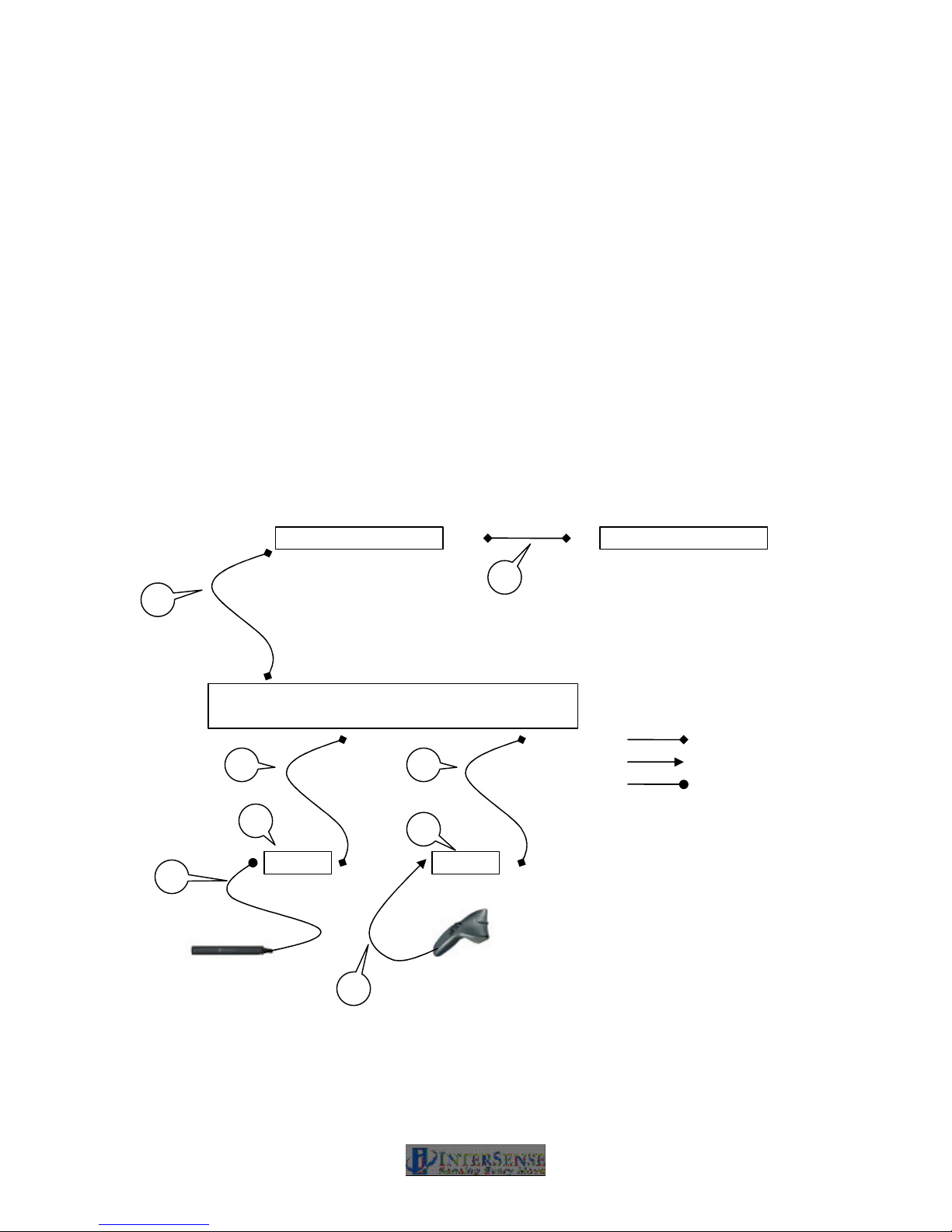
Figure 12 illustrates how the cables, connectors and adaptors are set-up for the wired version of
the IS-900 System and MicroTrax devices.
2
1
*Configuration
depends on your
constellation
Processor
1 1
4
3
6
Not – to - Scale
5
Figure 12 - Wired IS-900 and MicroTrax Cables, Connectors and Adapters
IS-900 User Guide Page 25 of 159
Page 26

1. Cable: Processor to SoniStrip or to MicroTrax device Adapter.
• Part no. 078-00088-0030
• 30 feet long
• RS422 communication
• 10-pin RJ-48 cable connector
This 30 foot cable provides basic +12 VDC power and transmits the SoniDisc trigger signals to
the SoniStrip Constellation array. It connects from the back of the IS-900 Processor (any PORT
#) to the SoniStrips and can run a maximum length of 15 meters (50 ft.)*.
*NOTE: Maximum length of the total SoniStrip daisy chain measured from the IS-900 Processor
to the end of the SoniStrip chain is 24 meters (80 ft.) without external power boosters.
This same cable is also used to connect the MicroTrax adapter to the processor.
2. Cable: SoniStrip to SoniStrip
• Part no. 078-00088-0004
• 4 feet long
• RS422 communication
• 10-pin RJ-48
The 4 foot SoniStrip to SoniStrip cable provides standard connectivity between each SoniStrip in
the Constellation array. The cable and connector type (10-pin RJ-48) are identical to the
Processor to SoniStrip Cable. The IS-900 SimTracker configuration can support a maximum of
12 SoniStrips (36 SoniDiscs) per system. The IS-900 VETracker configuration can support 84
SoniStrips (252 SoniDiscs) split between two ports with the use of external power boosters**.
**NOTE: Maximum length of total SoniStrip daisy chain measured from the IS-900 Processor to
the end of the SoniStrip chain and configured with power boosters can be greater than 90 meters
(300 ft.). Consult with InterSense for non standard configuration support!
3. Cable (Integral to the Head Tracker): Head Tracker to Adapter (ref. item 4)
• Part no. 100-91003-AWHT
• 3 feet long
• TTL communication
• Hirose connector
In order to keep the Head Tracker lightweight and unobtrusive, we use a TTL cable. However
this cable has limited length to processor capability. Therefore, we convert it to an RS-422
downstream closer to the processor.
4. Adapter: TTL to RS422
• Part no. 100-91000-AWDG
• Hirose Connector for TTL
• 10 pin RJ-485 connector for RS422
This adapter simply converts the TTL MicroTrax interface signals to a differential serial signal
(RS-422) in order to transmit the signals long distance to the IS-900 Processor. The interface RJ48 connector labeled “BASE” attaches to the Cable (ref. item 1). The Hirose connector connects
directly to the MicroTrax Head Tracker integral cable (ref. item 3).
5. Cable (Integral to Wand): Wand to Adapter (ref. item 6)
• Part no. 100-91012-AWWD
• 12 feet long
• RS232 Communication
• 6-pin RJ-11
This cable is fixed to the wand and uses RS-232 communication. It has limited length capability
therefore must be converted to an RS-422 downstream closer to the processor.
IS-900 User Guide Page 26 of 159
Page 27

6. Adapter: RS232 to RS422
• Part no. 100-SDPDL-001
• 10 pin RJ-45 connector for RS422
• 6-pin RJ-11 connector for RS232
This adapter simply converts the RS-232 MicroTrax interface signals to a differential serial signal
(RS-422) in order to transmit the signals long distance to the IS-900 Processor. The interface RJ48 connector labeled “BASE” attaches to the Cable (ref. item 1). The RJ-11 connector labeled
“TRACKER” connects to the MicroTrax Wand integrated cable.
IS-900 User Guide Page 27 of 159
Page 28
SoniStrip
* SoniStrip
*
2
Head Tracker
RJ48 RJ12 Hirose
Connector Symbols
Wand
7
WR WR
8
ATA
1.8.2. Wireless System
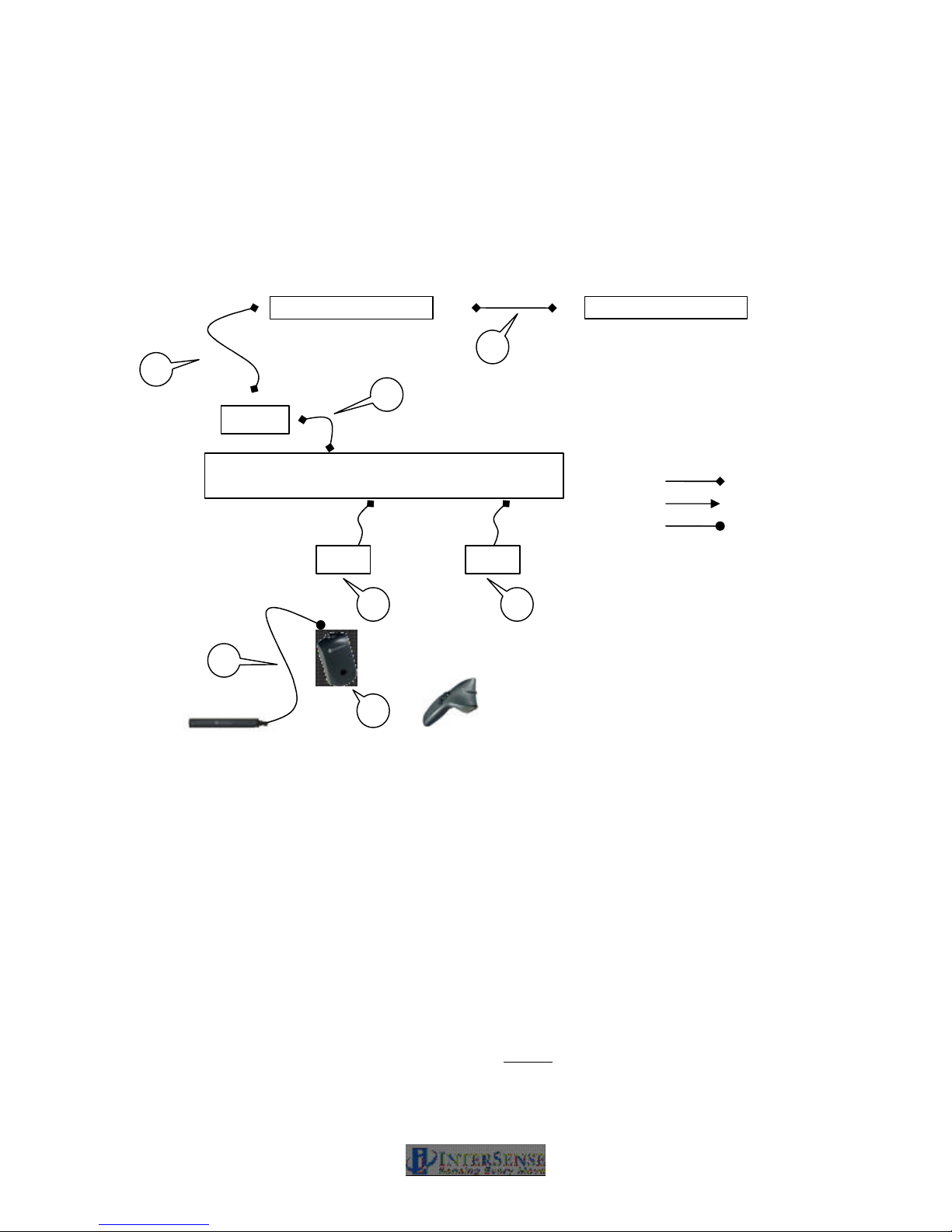
Figure 13 illustrates how the cables, connectors and adaptors are set-up for the wireless version
of the IS-900 System and MicroTrax devices.
* Configuration
depends on your
1
9
Processor
constellation
8
3
Not – to - Scale
Figure 13 - Wireless IS-900 and MicroTrax Cables, Connectors and Adapters
1. Cable: Processor to SoniStrip
• Part no. 078-00088-0030
• 30 feet long
• RS422 communication
• 10-pin RJ-48 cable connector
This 30 foot cable provides basic +12 VDC power and transmits the SoniDisc trigger signals to
the SoniStrip Constellation array. It connects from the back of the IS-900 Processor (any PORT
#) to the SoniStrips and can run a maximum length of 15 meters (50 ft.)*.
*NOTE: Maximum length of the total SoniStrip daisy chain measured from the IS-900 Processor
to the end of the SoniStrip chain is 24 meters (80 ft.) without external power boosters.
IS-900 User Guide Page 28 of 159
Page 29

2. Cable: SoniStrip to SoniStrip
• Part no. 078-00088-0004
• 4 feet long
• RS422 communication
• 10-pin RJ-48
The 4 foot SoniStrip to SoniStrip cable provides standard connectivity between each SoniStrip in
the Constellation array. The cable and connector type (10-pin RJ-48) are identical to the
Processor to SoniStrip Cable. The IS-900 SimTracker configuration can support a maximum of
12 SoniStrips (36 SoniDiscs) per system. The IS-900 VETracker configuration can support 84
SoniStrips (252 SoniDiscs) split between two ports with the use of external power boosters**.
**NOTE: Maximum length of total SoniStrip daisy chain measured from the IS-900 Processor to
the end of the SoniStrip chain and configured with power boosters can be greater than 90 meters
(300 ft.). Consult with InterSense for non standard configuration support!
3. Cable (Integral to the Head Tracker): Head Tracker to MicroTrax Wireless Transmitter (ref.
item 7)
• Part no. 100-91003-AWHT
• 3 feet long
• TTL communication
• Hirose connector
7. MicroTrax Wireless Transmitter for Head Tracker
• Part no. 100-91000-EWTX
This module transmits the data from the wireless head tracker to the head tracker’s receiver.
The Hirose connector attaches to the TTL cable integral to the head tracker.
8. MicroTrax Wireless Receiver
• Part no. 100-IS9MW-RX16
• Has integral cable that connects to the processor
• RS422 communication
• 10-pin RJ-48 cable connector
9. Cable for Acoustic Timing Adjuster
• Part no. 078-00088-0001
• 1 foot long
• RS422 communication
• 10pin RJ-48 cable connector
• Adjusts the timing of the beacons in the SoniStrips to match the timing of the MicroTrax
wireless devices.
1.8.3. All Systems
AC Power Cable, Part No. 078-00003-xx09 (“xx” for US/JP, UK, EU country code)
The IS-900 system ships with a 9 foot AC Power Cord to match the country voltage specification
on your order. The IS-900 Processor has an auto switching power supply module to supporting
AC voltage inputs from 100 to 240 VAC.
RS-232 Null Modem Serial Cable, Part No. 078-00001-0000 (IS-900 Processor to PC cable)
IS-900 User Guide Page 29 of 159
Page 30
The null modem cable provides both data and control communication between the IS-900 System
and your host computer. InterSense ships a 1.8 meter (6 foot) cable with the system. The
maximum specified length for RS-232 communication cabling is 7.6 meters (25 feet). A pin-out
and cable specification is located in FAQ’s Appendix below. The null modem cable connects to
the port labeled HOST on the IS-900 Processor.
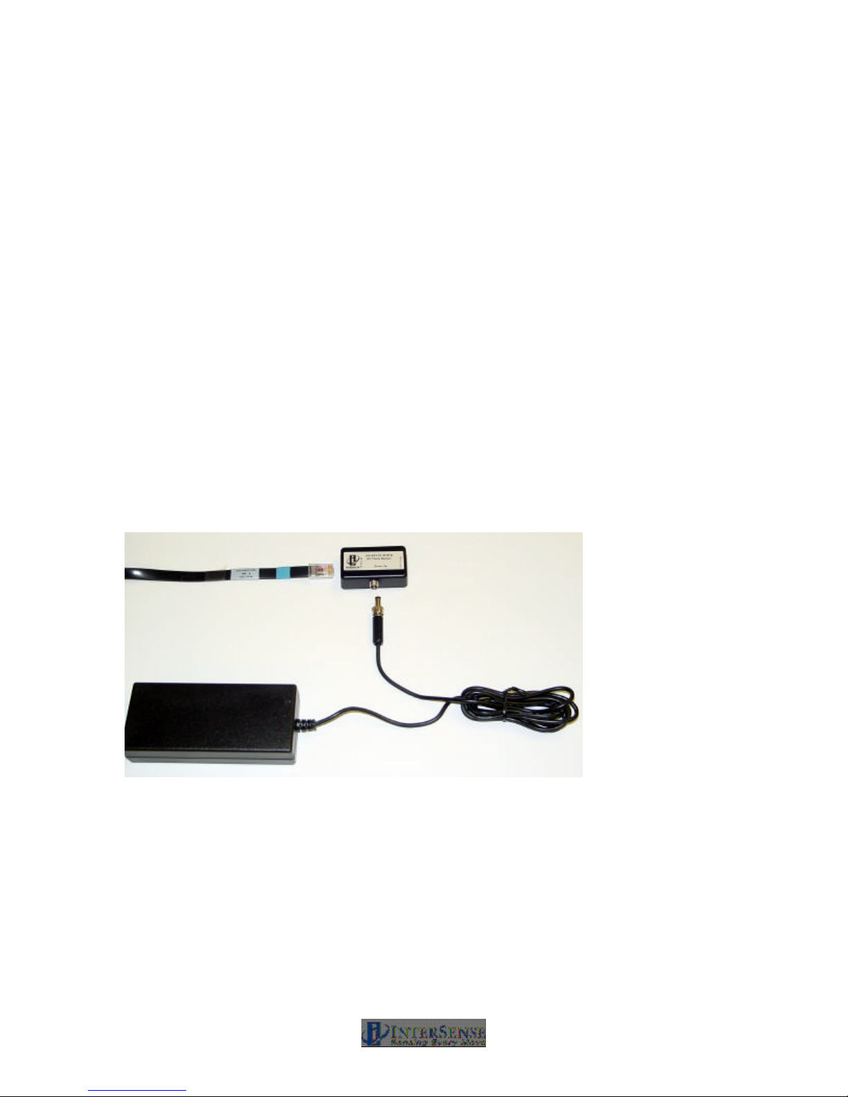
(Optional) SoniStrip Power Booster, Part No. ISC-REV3X-POWR
The optional SoniStrip Power Booster kit shown in Figure 14 comes with a +15 VDC power
supply w/ country specific line cord, a 4 ft. SoniStrip Cable (Part No. 078-00088-0004), and an inline power booster module (Part No. 100-REV3X-POWR). SoniStrip Power Booster Kits are
required for SoniStrip Constellation Arrays that meet at least one the following conditions:
• The initial Processor to SoniStrip Cable, Part No. 078-00088-00xx, is greater than 30 ft.
• The SoniStrip Constellation Array is configured with more than 12 SoniStrips.
• Any SoniStrip Constellation array requires an extended measurement range of up to 4
meters (13 ft.).
For condition (a) with just 12 SoniStrips in a Constellation Array, the Power Booster is inserted inline with the SoniStrip just before the first SoniStrip in the array. For condition (b), a Power
Booster is required after every 12th SoniStrip in a Constellation (i.e. it is added in-line after
between the 12th and 13th SoniStrip, the 24th and 25th SoniStrip, etc…). For condition (c), the
Power Boosters deploy as in-line components before the 1st SoniStrip and after every 12th
SoniStrip thereafter.
Figure 14 - SoniStrip Power Booster (Optional)
(Optional) Serial Wireless Radio Links, Part No. ISC-IS9S0-RFX0
For wireless conversion of MicroTrax Head Trackers, the Wireless Receiver and Transmitter
essentially replaces the Adapter: TTL to RS-422 and the cable from this adapter to the
processor.
(Optional) Ethernet Communications, Part No. ISC-LICEN-ETS0
The Ethernet communications option enables the IS-900 Processor to communicate through a
standard Ethernet network. The details of this interface are application specific, but in general,
IS-900 User Guide Page 30 of 159
Page 31
Ethernet communication is automatically supported by the InterSense libraries (isense.dll). When
connecting directly to another computer, an Ethernet cross-over cable is required. When
connecting to a standard network, where Ethernet hubs and routers are used, a straight through
Ethernet cable is required. Please consult with InterSense Technical Support
([email protected]) for specific questions about using the IS-900 Ethernet
communication interface.
Failure to power down the IS-900 Processor when connecting or disconnecting
tracked stations will cause damage to the tracked stations.
Exceeding maximum cable lengths will cause IS-900 to operate unreliably due
to signal transmission and timing errors.
1.9. IS-900 Support CD
The provided support CD has the latest version of all InterSense product specifications,
InterSense technical papers/notes, and IS-900 product documentation. The current version of
InterSense’s ISDEMO set-up, calibration, and product testing software is also available on the
support CD.
IS-900 User Guide Page 31 of 159
Page 32

2. Specifications
2.1. Performance Specifications
Degrees of Freedom: 6 (X, Y, Z, Yaw, Pitch, and Roll)
Tracking Device(s): MicroTrax Wired Head Tracker
MicroTrax Wired Wand (Standard with VETracker only)
Custom/OEM Devices (Consult InterSense)
Tracking Volume: Up to 20 m2 with 12 SoniStrips (SimTracker maximum)
Up to 140 m2 with 84 SoniStrips (VETracker maximum)
2.0 m x 2.0 m x 3.0 m maximum w/ SoniFrame (optional)
1.5 m x 1.5 m x 3.0 m with SoniWing (optional)
Angular Range: Full 360º - All Axes
Resolution: 0.75 mm (1.5 mm Wireless)
0.05º (0.10º Wireless)
Static Accuracy: 2.0 to 3.0 mm (3.0 to 5.0 mm Wireless)
0.25º RMS in Pitch & Roll, 0.50º RMS in Yaw
0.50º RMS in Pitch & Roll, 1.00º RMS in Yaw (Wireless
MicroTrax)
Update Rate: 180 Hz Nominal
120 Hz Minimum (Wireless SimTracker & VETracker)
Latency: 4 ms Typical (without prediction @ 115 kbaud)
Maximum number of devices 4 for SimTracker (Wired or Wireless)
7 for VETracker (Wired or Wireless)
Interface: RS-232 Serial Port
Ethernet (Optional)
O/S Compatibility: Windows /2000/Millenium/XP, Linux, SGI IRIX, Sun Solaris,
HP AUX, Mac OS X, VISTA
Software Support: SDK with full InterSense API
ISDEMO control & connectivity software
Additional Specification for Wireless Devices
Device charge time 3 hours
Number of charges 500
Constant Tracking Time 6-8 hours on one charge
Radio Technology 2.4 GHz non-frequency hopping spread spectrum
Radio Range (Indoor) 100 Feet (with no major obstructions)
Radio Channels 16
IS-900 User Guide Page 32 of 159
Page 33
2.2. Physical Specifications
AC Input: 100 to 120 V/200 to 240 V, 60/50 Hz, 6/3 A (auto switching)
Operating Temperature: 0º C to 50º C (32º F to 122º F)
Storage Temperature: -20º C to 70º C (-4º F to 158º F)
Standard Cable Lengths: IS-900 to SoniStrips – 10.7 m
IS-900 to Tracking Devices – 12.0 m
IS-900 to Host (RS-232 Serial) – 1.8 m
Maximum Cable Lengths: System configuration dependent – Consult InterSense
Processor Size: 1 U rack mounted (44.45 cm wide x 40.64 cm deep x 4.45
cm tall)
Processor Weight: 6.8 kg
SoniStrip Size Weight
2 foot 0.61 m x 3.7 cm x 2.5 cm 0.4 kg
4 foot 1.22 m x 3.7 cm x 2.5 cm 0.9 kg
6 foot 1.83 m x 3.7 cm x 2.5 cm 1.3 kg
MicroTrax Devices Size (outside dimensions) Weight
Standard Head Tracker 10.15 x 1.54 x 1.38 cm 40 g (Includes wire)
Wand 17.48 x 10.16 x 5.38 cm 140 g wired (170 g
wireless)
Wireless Transmitter 7.62 x 4.45 x 3.40 cm 65 g
Wireless Receiver 5.3 x 3.5 x 2 cm 45.4g (includes wire)
2.3. Environmental Specifications
When disposing of electronic equipment please do so responsibly in accordance with local
requirements.
Normal environmental conditions
This standard applies to equipment designed to be safe at least under the following conditions:
a) indoor use;
b) altitude up to 2 000 m;
c) temperature 0 °C to 50 °C;
d) maximum relative humidity 80 % for temperatures up to 31 °C decreasing linearly to 50 %
relative humidity at 40 °C;
e) MAINS supply voltage fluctuations up to ±10 % of the nominal voltage;
f) transient over voltages typically present on the MAINS supply.
g) Applicable rated pollution degree 2 environment.
10
ISO
7000-
0434
Attention, consult accompanying documents
In case of application as a safety sign, the rules according to ISO 3864-1 are to be
adhered to. See safety sign ISO 3864-1, B.3.1, “General warning, caution, risk of
danger”.
IS-900 User Guide Page 33 of 159
Page 34

3. Installation and Set-up
This section reviews the background information needed to understand how the IS-900 system
works. It then covers the detailed steps required for set-up and calibration of the IS-900 tracking
system in typical virtual or simulation environments. References made to other parts of this
manual or to supplemental manuals provide additional background material.
The detailed set-up steps below assume an IS-900 VETracker is being used for a typical
immersive display environment with a wired MicroTrax Head Tracker and a wired MicroTrax
Wand. Systems purchased for different applications, such as cockpit simulators, may require
technical support from InterSense to complete the installation, although the basic steps covered
here are applicable for all IS-900 tracking configurations.
Check IS-900 Firmware Version
Upgrades to an existing IS-900 System may require you to upgrade also the firmware in the IS900 Processor. The Wireless Tracking modules with the IS-900 VWT or VET processors require
firmware version 4.14 or higher to operate.
Wireless Tracking Modules with the IS-900 SimTracker or VETracker processors require firmware
version 4.20 (MiniTrax) or 4.23 (MicroTrax) or higher to operate.
To check if your IS-900 system needs a firmware upgrade, follow these steps:
1. Power on the IS-900
Shortcut→ Use the front panel buttons and LCD menus to determine the IS-900 firmware
version by pressing the Enter key, arrow key down to System Config, select Enter again,
select Information to read Firmware revision number. Or use ISDEMO as follows.
2. Connect the PC to the IS-900 processor using the null modem cable provided with your
system.
3. Launch ISDEMO to determine the firmware version installed in the IS-900 Processor
(with ISDEMO, this information is found under the Tools→System Information menu).
4. If the version number shown is lower than the version specified above for your IS-900
processor configuration, you will need to upload a new version of firmware to the IS-900
processor.
If you believe you require a Firmware Upgrade for the IS-900 System, please contact
InterSense Technical ([email protected] or +1 781 541-7624) support for
assistance with selecting the correct firmware needed with your system. The necessary
download and instructions can also be found by logging into the support section of our
website.
IS-900 User Guide Page 34 of 159
Page 35
3.1. InterSense Coordinate Reference Frame
Before setting up the IS-900, it is important to review the standard InterSense coordinate
reference system. As a 6-DOF tracker, use of the “InterSense Coordinate Reference Frame”
throughout this manual helps explain the installation, calibration and tracking performance.
X
Roll
Y
Pitch
Yaw
Z
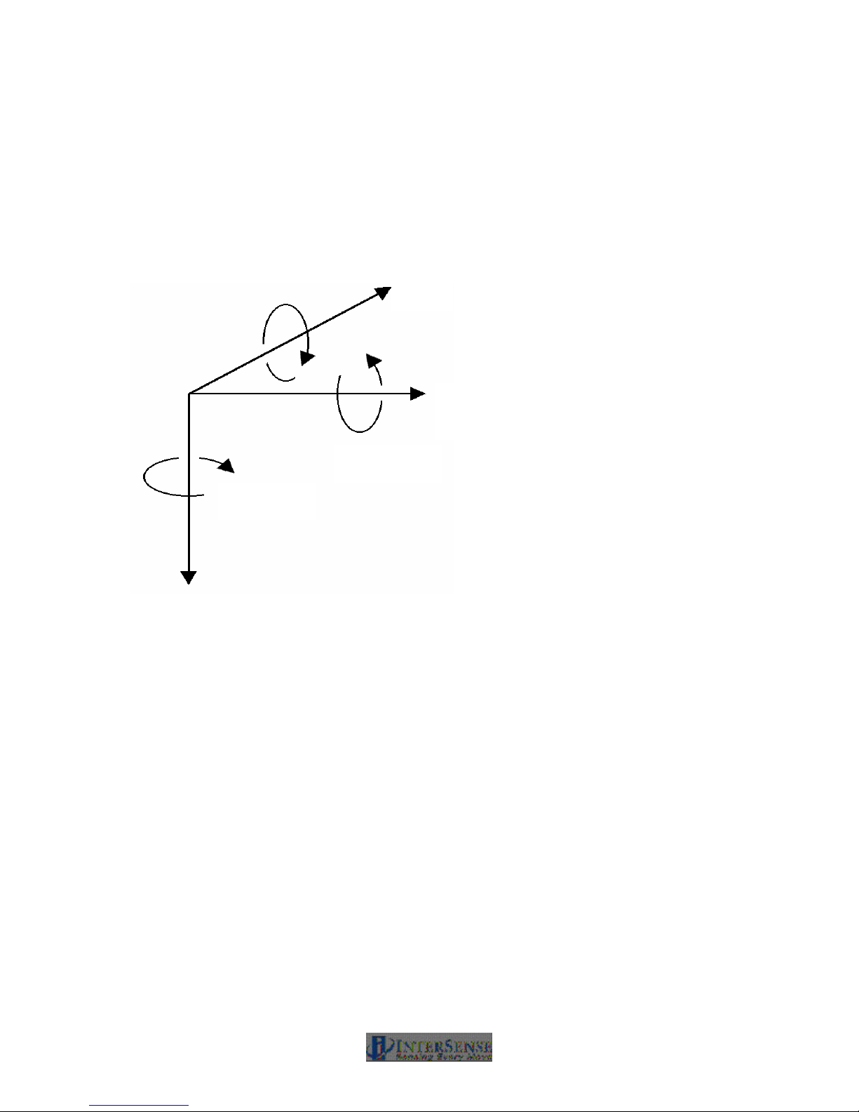
Figure 15 - InterSense Coordinate Reference Frame
Figure 15 shows the standard reference frame for both position and orientation of all InterSense
tracker systems.
The reference frame (hereafter referred to as Navigation frame or Nav frame or N frame) is the
locally-level geographic frame with its x-axis pointing north, y-axis east, and z-axis down.
It is important to understand that when setting up any InterSense system, the z-axis of the
tracking system’s coordinates must always point in the direction of gravity, whereas the x
and y axes may be set to any direction rotated about the z-axis.
Subsequent coordinate transformations by application software to change the direction of the zaxis are normal, but the underlying reference of InterSense’s inertial components to gravity must
be maintained by the tracking system. The Euler angles reported by the tracker are described as
a sequence of rotations applied to the tracking device starting with its body axes initially aligned
with the Nav frame axes and resulting in the current orientation. The sequence starts with a
rotation by (+yaw) about the Z axis, followed by a rotation by (+pitch) about the new Y axis (i.e.
body frame axis), followed by a rotation by (+roll) about the new X axis (i.e. body frame x axis).
IS-900 User Guide Page 35 of 159
Page 36
3.2. Hardware Set-up
General Equipment Handling Warnings
The ultrasonic transmitters (SoniDiscs) are sensitive electronic
components. Take care not to allow any dirt or moisture in or around the
SoniDiscs install the SoniStrips, SoniFrame, SoniWing or SoniPods.
Mishandling can damage both the ultrasonic receiver microphones and the
embedded InertiaCube in each tracked station.
Do not drop the tracked stations. While InterSense has designed the
devices for normal usage in simulators and virtual environments,
excessive shock can damage the internal components.
Always turn off the IS-900 Processor (remembering to save any
configuration changes) before plugging or unplugging the tracked
stations. Failure to do this could result in damage to the stations.
Always store the tracked devices in a secure location when not in use.
Leaving them on the floor or on an unsecured surface can result in
accidental damage.
This section covers a typical installation of the IS-900 with standard components. Consult
InterSense for non-standard or OEM installations.
The basic steps covered in this section include:
• Installation of SoniStrips
• Mount and Calibration of SoniStrips
• Connection and Test with the IS-900 Processor.
• Special Instructions for Wireless Devices
Unpack all components and check against packing list (standard configuration referenced in
Section 1.2 for the IS-900 SimTracker and 1.3 for the IS-900 VETracker). Check the packing list
that came with the system as many orders will not match the standard configurations shown in
Section 1. Contact InterSense if any components are missing or appear damaged.
IS-900 User Guide Page 36 of 159
Page 37

3.3. Installation of SoniStrips
In order to install the SoniStrips, you need the following (that are not supplied in the standard IS900 System):
1. An optical surveying tool or Total Station. We recommend a Nikon DTM 420 or equivalent for
measuring absolute x, y, and z coordinates of all SoniDiscs.
Note: If your IS-900 system comes with a fixed constellation frame (SoniFrame or
SoniWing), then the optical surveying equipment is not needed.
2. A Windows FC capable of running the latest version of ISDEMO (check
www.intersense.com/support for current version).
General Guidelines
The position of a SoniDisc is defined as the coordinates of the center of the grill covering the
speaker. When measuring the position of each SoniDisc in an installed Constellation Array, all
values are entered in meters. The coordinates of the SoniDiscs are entered in a user-defined,
locally leveled coordinate frame. The coordinate system is right-handed with X pointing forward,
Y to the right and Z pointing down. Position data for all stations is computed relative to that
coordinate system.
SoniStrips come in 0.6, 1.2 or 1.8 meter (2, 4 or 6 foot) lengths. The 2-ft. SoniStrip has two
SoniDiscs per SoniStrip and the 4-ft SoniStrip has 3 SoniDiscs installed with each SoniDisc
spaced at 0.61 m (2 foot). The 6-ft SoniStrip has 3 SoniDiscs with each spaced at 0.91 m (3 foot)
spacing. For best performance, it is generally recommended that SoniStrips be installed in a
regular grid over the tracked area. Total distance from a SoniDisc in the Constellation to a
tracked station should not exceed 3.0 meters (10 feet) to guarantee good signal detection (4
meters with external power boosters installed).
IS-900 default configuration does not contain a Constellation, so it is up to the user to configure it.
To properly track, the system needs to know the position and orientation of each of the SoniDiscs
in the Constellation? with high degree of accuracy. The best way to measure position of each
SoniDisc is with the use of an optical sighting tool known as a Total Station. The quality of the
measured position data input for the SoniStrip Constellation Array is directly proportional to the
accuracy of the IS-900 system’s tracking data output.
A second parameter needed for each SoniDisc in the installed Constellation Array is the unit
normal vector, as shown in Figure 16. The unit normal vector defines the orientation of a
SoniDisc. The default assumption is that the Constellation is installed horizontally over the
tracked area, so the normal vector points straight down with unit normal vector coordinates of 0,
0, 1. The unit normal vector is the same for each SoniDisc on the same SoniStrip. Entering the
correct normal vector for each SoniDisc is important. The normal vector information is used by
the IS-900 tracking algorithm to correctly schedule the polling of each SoniDiscs.
IS-900 User Guide Page 37 of 159
Page 38
SoniStrips
SoniDisc Emitter
Normal vector pointing down
0, 0, 1
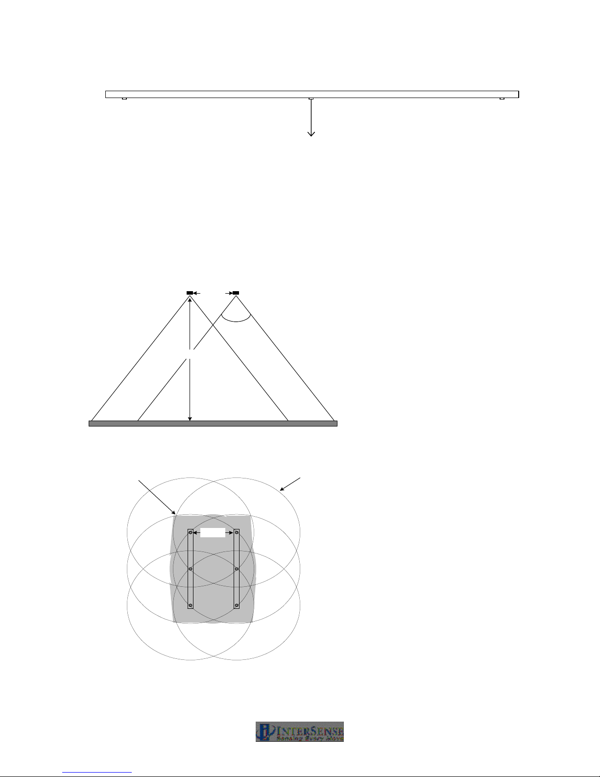
Figure 16 - Unit Normal Vector Definition for Ceiling Installed SoniStrip
The SoniStrip Constellation Array provides an absolute positional reference to the tracked
environment. The idea behind providing SoniDiscs (beacons) in groups of three in each SoniStrip
(rail) is to give flexibility in both the configuration and installation to cover a wide range of tracking
environments in a convenient package for ease of installation. To establish a minimum criterion
for a tracked environment, at least two SoniStrips are required to provide proper tracking. A
conceptual diagram using two SoniStrips, shown in Figure 17, provides the fundamental
relationship established by the SoniStrip Constellation with respect to the tracking environment.
Side view of SoniStrips
0.67 m
70 degree
acoustic cone
Area of optimal
tracking at 1m to 2 m from
SoniStrip Constellation
3 m
Floor
Top view of SoniStrips
0.67 m
Area of Single SoniDisc
Coverage at 2 m from
SoniStrip Constellation
Figure 17 - Tracking Coverage with Two SoniStrips
IS-900 User Guide Page 38 of 159
Page 39

When preparing the installation for SoniStrips or SoniPods, it is very important to assure the
following in order to maintain stable tracking conditions:
1. The mounting surface is rigid and stable
2. The relative position between SoniStrips or SoniPods remains fixed
Note: If either of these two conditions is not met, then the performance of the tracking
system will degrade and possibly fail. InterSense will not warrant a system to track with
improper installation.
For larger or first time installations, we recommend you contract InterSense to perform onsite installation and training. Please contact your InterSense representative for details.
Sections 3.3.1, 3.3.2 and 3.3.3 describe three examples of typical tracking system installations:
• SoniStrip Mounting for Ceiling Installations
• SoniStrip Mounting for Power Wall Installations
• SoniStrip Mounting for CAVE-like Installations
IS-900 User Guide Page 39 of 159
Page 40
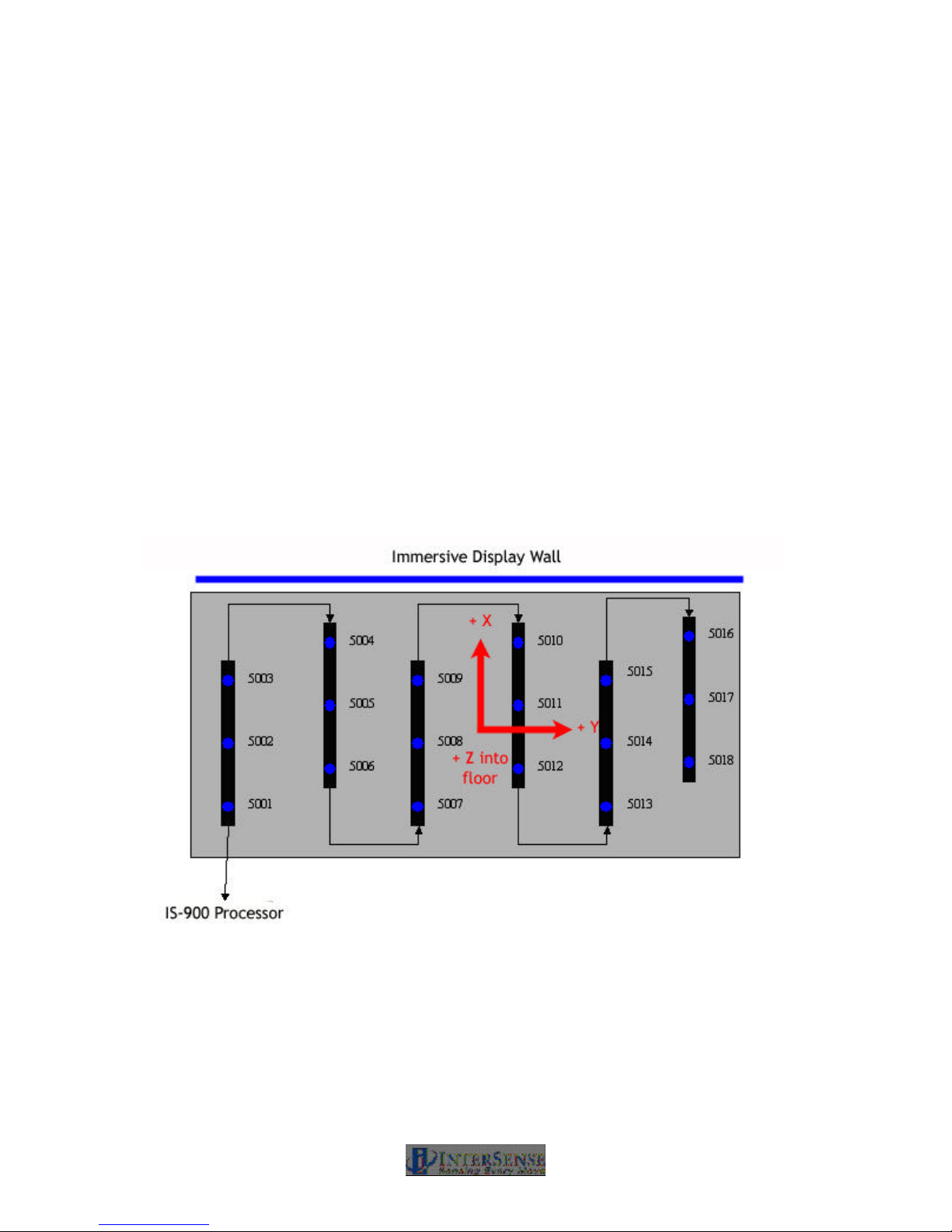
3.3.1. SoniStrip Mounting for Ceiling Installations
The following is an example of an installation for a large area immersive room environment.
Important Note:
For customers upgrading existing MiniTrax systems to work with wireless MicroTrax devices – an
InterSense acoustic timing adjuster (ATA) must be inserted in series with the rails in between the
processor and the first beacon in the chain. The ATA allows users with revision 3.0 rails to use
wireless MicroTrax devices more effectively (improves tracking at close range). New systems
using the revision 3.1 rails do not need this ATA.
Most applications for IS-900 systems are best realized with a ceiling mounting of several
SoniStrips in either a grid-like pattern or a staggered pattern as depicted in Figure 18 below. In
both cases, 6-ft. SoniStrips are mounted to the ceiling using InterSense provided ceiling clips that
attach directly to most all suspended ceiling systems.
The SoniStrips are mounted approximately 2 to 3 feet apart, depending on the ceiling height. For
ceilings that are 8 feet high, mount SoniStrips with 2 ft separation. For lower ceilings, consider
using 4-ft. SoniStrips mounted 2 feet apart. For ceiling mounts from 9 to 12 feet high, mount 6-ft
SoniStrips approximately 3 feet apart and plan on using external power boosters to maximize the
acoustic measurement range of the IS-900.
Figure 18 - Immersive Room Ceiling Mounting (top down view)
In Figure 18, the coordinate system is shown from a “top down view”, identical to the default
Constellation Array view used with the InterSense set up software ISDEMO. Each SoniStrip is
wired in sequence from the lower left hand corner of the SoniStrip Constellation Array connecting
to Port 5 on the IS-900 Processor.
Definition of the SoniStrip ID numbers come from the wiring sequence, or “daisy chain”, and IS900 Processor port number that is used to connect to the Constellation Array. Here, the SoniStrip
IS-900 User Guide Page 40 of 159
Page 41
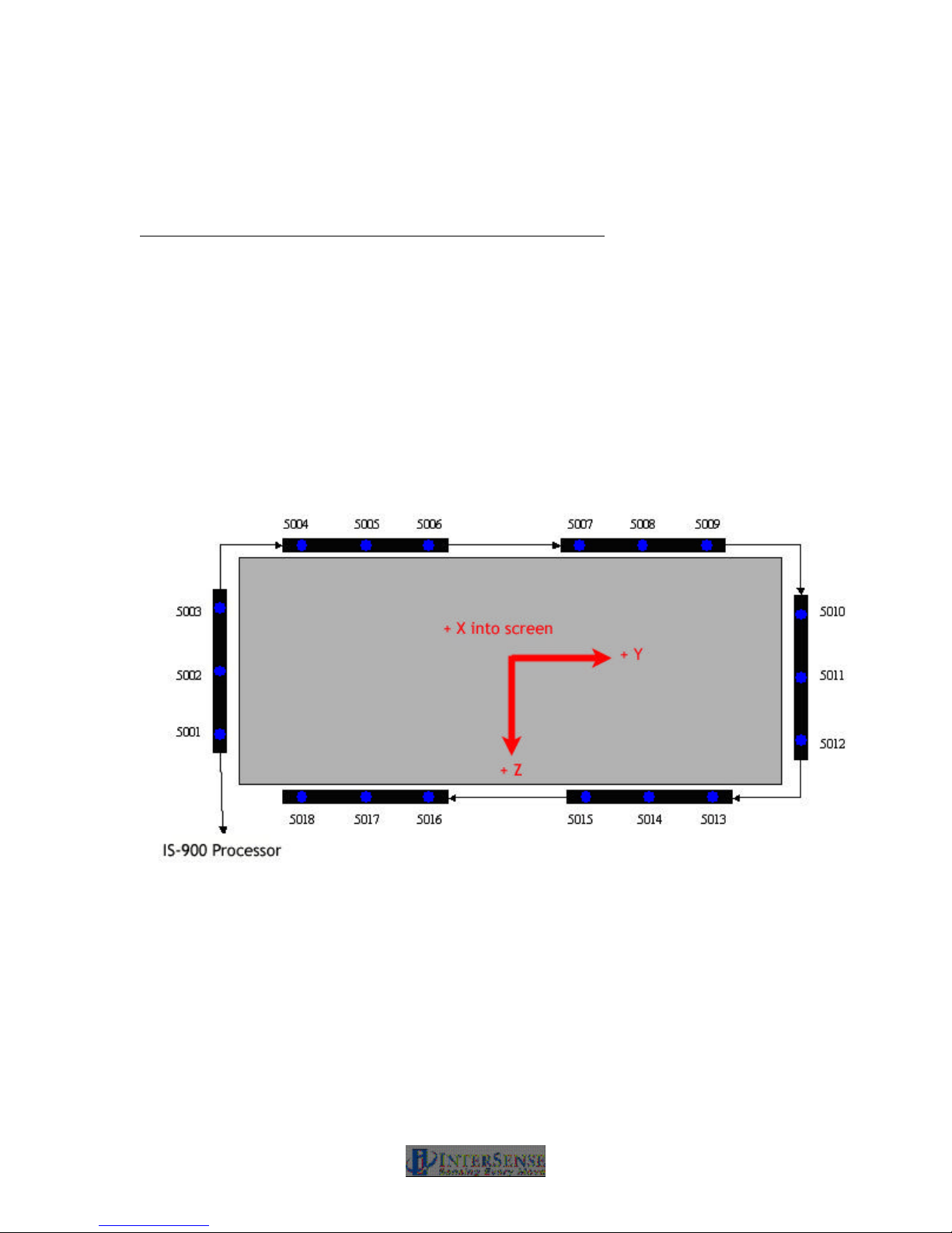
Array is plugged into Port 5 thus becoming a sequence with SoniDisc ID numbers from 5001 to
5018.
With each SoniStrip mounted in the same orientation on the ceiling and pointing down, the normal
vectors then for the installation and wiring shown in Figure 18 become:
SoniDisc ID Nos. Normal Vectors used in Constellation Array
5001 – 5018 0.000, 0.000, 1.000
3.3.2. SoniStrip Mounting for Power Wall Installations
The following is an example of an installation for a typical power wall.
A typical immersive display wall consists of one or more stereo projectors that illuminate a flat (or
curved) screen. This type of display is ideal for mounting the IS-900 SoniStrips surrounding the
screen with each SoniStrip angled at 45 degrees towards the center of the screen. Figure 19
shows a typical, two-projector, flat display using six, 6-foot SoniStrips in a perimeter mount
configuration.
Figure 19 - Power Wall Perimeter mounting (front forward view)
Each SoniStrip is mounted along the edge of the display using the InterSense provided angle
brackets. The SoniStrips on the top and bottom of the display are spaced approximately 2 to 3
feet apart, depending on the size of the display wall. The InterSense coordinate system for
Figure 19 has X forward looking into the screen, Y positive to the right, and Z positive down in
the direction of gravity.
Each SoniStrip is wired in sequence with the bottom left corner connecting to Port 5 of the IS-900
Processor. The SoniStrip ID numbers are defined by the wiring and port number and become a
sequence with numbers from 5001 to 5018.
IS-900 User Guide Page 41 of 159
Page 42
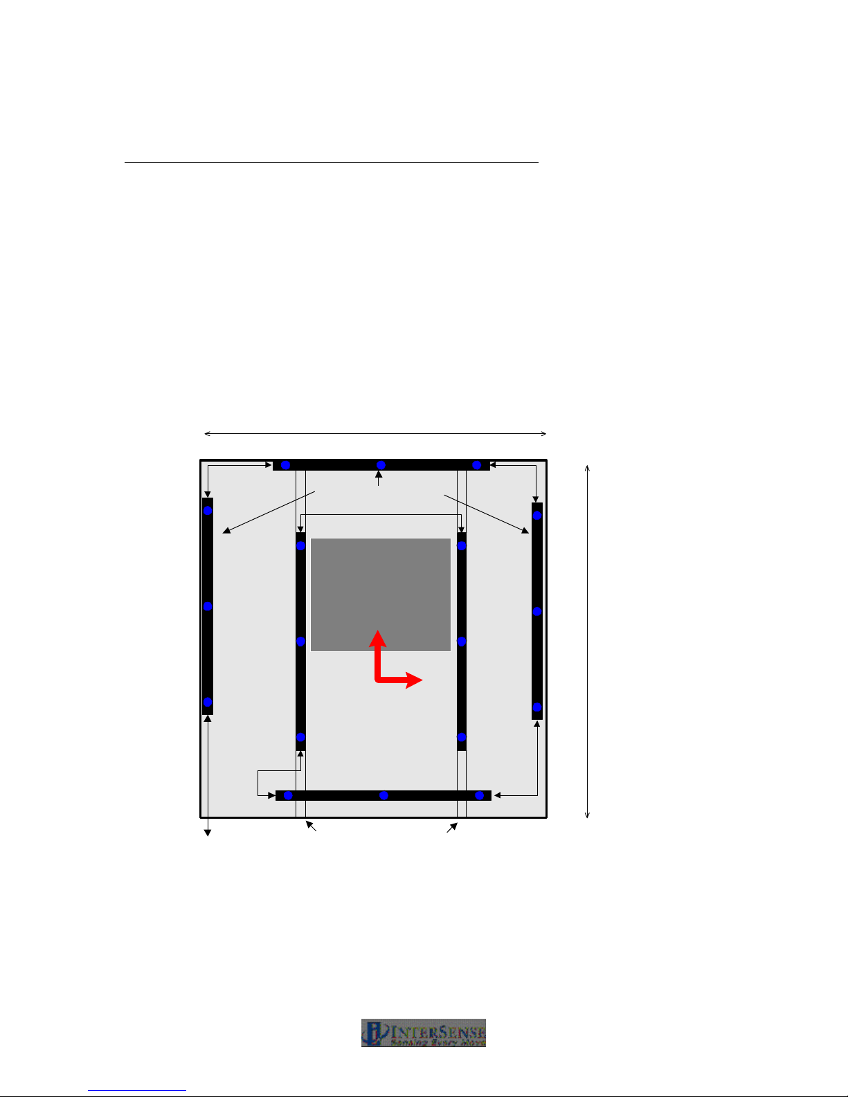
With each SoniStrip angled at 45 degrees toward the screen center, the normal vectors for the
IS-900 Processor
installation and wiring shown in Figure 19 become:
SoniDisc ID Nos. Normal Vectors used in Constellation Array
5001 – 5003 -0.707, 0.707, 0.000
5004 – 5009 -0.707, 0.000, 0.707
5010 – 5012 -0.707, -0.707, 0.000
5013 – 5018 -0.707, 0.000, -0.707
3.3.3. SoniStrip Mounting for CAVE-like Installations
The following is an example of an installation for a typical CAVE-like environment.
The IS-900 excels over magnetic or optical trackers in CAVE-like installations. As shown in
Figure 20, the SoniStrips are positioned to provide uniform tracking coverage throughout the
entire immersive display environment with no distortion or occlusion issues.
3 meters
5004
5005 5006
SoniStrips Mounted at
5003
5015
45 degree angles
5007
5016
Mirror
5002
5014
+ X
5008
5017
3 meters
+ Y
5001
5013
5012 5011 5010
Additional Mounting Support
Figure 20 - CAVE-like Installation (top down view)
The example above is a 3 meter cube, 4 walled immersive display system which uses six 6-ft.
SoniStrips. Depending of the number of display walls, display volume and mirror position/size, it
may be necessary to use a variety of different sized SoniStrips (6, 4, and 2 foot) or SoniPods
discretely located to provide the optimum tracking coverage. Please consult with InterSense
regarding all CAVE-like installations to maximize the tracking performance.
+ Z
into floor
5009
5018
IS-900 User Guide Page 42 of 159
Page 43

The first three SoniStrips mounted along the top and around the perimeter of the CAVE walls, are
angled in towards the CAVE center at 45 degrees. The remaining three SoniStrips are mounted
with the normal vectors pointing straight down on each side of the center ceiling mirror and along
the back side of the CAVE. The mounting of these three interior SoniStrips may require the
addition of two U-Channels, positioned front to back, on each side of the mirror at the top, center
of the CAVE.
Each SoniStrip is wired in sequence with the bottom left corner connecting to Port 5 of the IS-900
Processor. The SoniStrip ID numbers are defined by the wiring and port number and become a
sequence with numbers from 5001 to 5018.
With three perimeter SoniStrips angled at 45 degrees toward the CAVE center and the three
interior SoniStrips pointing straight down in the Z-axis, the normal vectors then for the installation
and wiring shown in Figure 24 become:
SoniDisc ID Nos. Normal Vectors used in Constellation Array
5001 – 5003 0.000, 0.707, 0.707
5004 – 5006 -0.707, 0.000, 0.707
5007 – 5009 0.000, -0.707, 0.707
5010 – 5018 0.000, 0.000, 1.000
3.3.4. SoniFrame and SoniWing
Please refer to the IS-900 Product Supplement Manual titled “IS-900 Fixed Frame Assemblies—
SoniFrame & SoniWing”, Doc. No. 072-00088-0G04, for details on the assembly and set up of
these pre-calibrated SoniDisc Constellation Arrays.
The InterSense installation and testing software, ISDEMO, has commands in the Constellation
Tool that allow rapid installation and calibration of the SoniWing and SoniFrame. This tool
automatically generates both the position and normal vectors for these fixed frame, factory
calibrated SoniDisc Constellation options. Refer to Section 14.7 for information about using
ISDEMO to install SoniWing and SoniFrame Constellation Arrays.
3.4. Measurement and Calibration of SoniStrips
Once the SoniStrip Constellation array is installed and wired, the next step is to accurately
measure the absolute positions of each SoniDisc in the array.
Two methods can be used to calibrate the installed SoniStrip beacon array:
1. Optical Surveying (sighting with a surveying tool, i.e. a Nikon total station). This is the most
precise method of calibration. Use this method for installations in all virtual environments.
2. Direct Measurement (hand measurement with a tape measure). This technique is not
recommended for most installations; but, can be used to quickly test an IS-900 installation
when the first technique cannot be done. ISDEMO has SoniStrip positioning and alignment
tools that help when performing a quick installation using the direct measurement approach.
Refer to Section 14.7 for details.
NOTE: In calibrating the SoniStrip constellation array, it is very important that the
measurements are as accurate as possible. Accurately measuring the SoniStrip beacon
IS-900 User Guide Page 43 of 159
Page 44

constellation array will directly impact tracking performance. Use a Total Station (Nikon DTM 420
or equivalent), or other means to accurately measure the absolute position vector for each
SoniDisc. Contact InterSense for Total Station recommendations or installation support.
When measuring the SoniStrip Constellation Array with a Total Station:
1. Read the manufacturer’s instructions on the set-up and operation of the surveying tool. Make
sure the measurement tool can report absolute X, Y, and Z coordinates for each
measurement. The IS-900 Tracking system needs the X, Y, and Z position measurement for
each SoniDisc location in order to properly track.
2. Measure the X, Y, Z coordinates of each SoniDisc and write down the measurements in a
table listing beacon position (x, y, z values in meters), normal vector (for ceiling applications
the normal vector nx, ny, nz are always 0.00, 0.00,1.00). The SoniDisc ID number is
determined by the port the SoniStrip “daisy chain” is plugged in to (i.e. Port 5 for our
examples is Section 3.3) and the sequence number in the daisy chain (i.e. the first SoniStrip
in a daisy chain will have SoniDisc ID’s 5001, 5002 and 5003).
For example: 1.2000, 0.0000, 0.0000, 0.00, 0.00, 1.00, 5001
Sample sheet to enter X, Y, Z measurements of each beacon
X Y Z Nx Ny Nz Beacon #
IS-900 User Guide Page 44 of 159
Page 45

3. Using the InterSense command format:
MCF{beaconNum}, X, Y, Z, Nx, Ny, Nz, beacon ID
Where,
{beaconNum} is a sequential number (i.e. 1, 2, 3, …)
X, Y, Z are the beacon locations in meters in nav-space (x forward, y to the right, z down),
Nx, Ny, Nz are the pointing vectors of the beacon, usually they point down in the +Z direction so
entering 0,0,1, is correct; and,
BeaconID is the SoniDisc number determined by the “daisy chain” sequence of the SoniStrips for
that specific beacon (i.e. with SoniStrips plugged into port 5, the sequence starts at 5001, 5002,
5003, 5004, etc…).
Enter beacon locations in meters into comma delimited text file (.txt) using WordPad or any text
editing application on your PC in the following format shown in the example below.
Example of .txt file with X, Y, Z measurements
MCC
MCF1, 0.0000, 0.0000, -3.0000, 0.00, 0.00, 1.00, 5001
MCF2, 0.0000, 0.9144, -3.0000, 0.00, 0.00, 1.00, 5002
MCF3, 0.0000, 1.8288, -3.0000, 0.00, 0.00, 1.00, 5003
MCF4, 0.6000, -0.5050, -3.0000, 0.00, 0.00, 1.00, 5004
MCF5, 0.6000, 0.4094, -3.0000, 0.00, 0.00, 1.00, 5005
MCF6, 0.6000, 1.3238, -3.0000, 0.00, 0.00, 1.00, 5006
MCF7, 1.2000, 0.0000, -3.0000, 0.00, 0.00, 1.00, 5007
MCF8, 1.2000, 0.9144, -3.0000, 0.00, 0.00, 1.00, 5008
MCF9, 1.2000, 1.8288, -3.0000, 0.00, 0.00, 1.00, 5009
MCF10, 1.8000, -0.5030, -3.0000, 0.00, 0.00, 1.00, 5010
MCF11, 1.8000, 0.4114, -3.0000, 0.00, 0.00, 1.00, 5011
MCF12, 1.8000, 1.3258, -3.0000, 0.00, 0.00, 1.00, 5012
MCF13, 2.4000, 0.0030, -3.0000, 0.00, 0.00, 1.00, 5013
MCF14, 2.4000, 0.9174, -3.0000, 0.00, 0.00, 1.00, 5014
MCF15, 2.4000, 1.8318, -3.0000, 0.00, 0.00, 1.00, 5015
MCF16, 3.0000, -0.5030, -3.0000, 0.00, 0.00, 1.00, 5016
MCF17, 3.0000, 0.4114, -3.0000, 0.00, 0.00, 1.00, 5017
MCF18, 3.0000, 1.3258, -3.0000, 0.00, 0.00, 1.00, 5018
MCe
IS-900 User Guide Page 45 of 159
Page 46

3.5. Connections with IS-900 Processor
This section describes the final steps to setting up the IS-900 system.
1. Connect all the tracking devices and SoniStrip Constellation Array to the IS-900
Processor
Important! Always power down the IS-900 Processor and any external power boosters prior to
connecting or removing any cables. DO NOT “hot plug” any devices into the IS-900 Processor –
connecting devices to the IS-900 while the power is on will result in damage to both the IS-900
Processor and the tracking devices.
Wired MicroTrax Devices
For wired MicroTrax Devices, please see Figure 12. If you have a MicroTrax Head Tracker, it
connects directly to the Adapter: TTL to RS422, (item 4 in Figure 12). If you have a wand, it
connects directly to the Adapter:RS232 to RS422, (item 6 in Figure 12).
Next, connect the adapter(s) to the processor using the 30 ft. cable (part number 078-00088-
0030). Either adapter uses the same cable to the processor. You can use Ports 1, 2, 3, 4, 6, 7 or
8 on the VETracker for tracking devices or a second SoniStrip Constellation “daisy chain.”
However the SimTracker has only Ports 1, 2, 3 and 4 available for tracking devices or a second
SoniStrip Constellation “daisy chain.”
Next, connect the SoniStrip Constellation Array into Port 5 on the back of the IS-900 Processor
using the 30 ft. cable (part number 078-00088-0030).
Wireless MicroTrax Devices
For wireless MicroTrax devices, please see Figure 13. If you have a MicroTrax Head Tracker, it
connects directly to the MicroTrax Wireless Transmitter (item 7 in Figure 13). Whether you have
a Head Tracker, a Wand or both, each needs a Wireless Receiver. Simply connect the integrated
cable on the Wireless Receiver into the Processor.
Connect the SoniStrip Constellation Array into the Acoustic Timing Adapter (item 9/ATA in Figure
13). Then connect the ATA into Port 5 on the back of the IS-900 Processor. Similar to wired
devices, additional tracking devices or a second SoniStrip Constellation “daisy chain” can use
Ports 1, 2, 3, 4, 6, 7, or 8 on the VETracker. The SimTracker has only Ports 1, 2, 3 and 4
available for additional tracking devices or a second SoniStrip Constellation “daisy chain.”
Important Note: Each SoniStrip Constellation “daisy chain” needs one ATA. If you use
additional constellations, then you will need an additional ATA for each additional constellation.
When connecting the cables to the IS-900 system, please always follow these guidelines:
• Only use supplied cables to connect the SoniStrips to the IS-900 Processor. DO
NOT use standard phone cables or network cables, as they do not have the
correct pin-outs used with the IS-900 tracking system.
• If a need arises to build additional cables, use RJ48 flat cabling and RJ48
connectors. Call InterSense Technical Support for a detailed specification or with
any cabling questions (+1 781 541 7624).
A Power booster (Figure 21) must be connected in between the end of the SoniStrip “daisy
chain” and Port 5 of the IS-900 Processor to supply the additional power to the SoniDiscs for:
IS-900 User Guide Page 46 of 159
Page 47
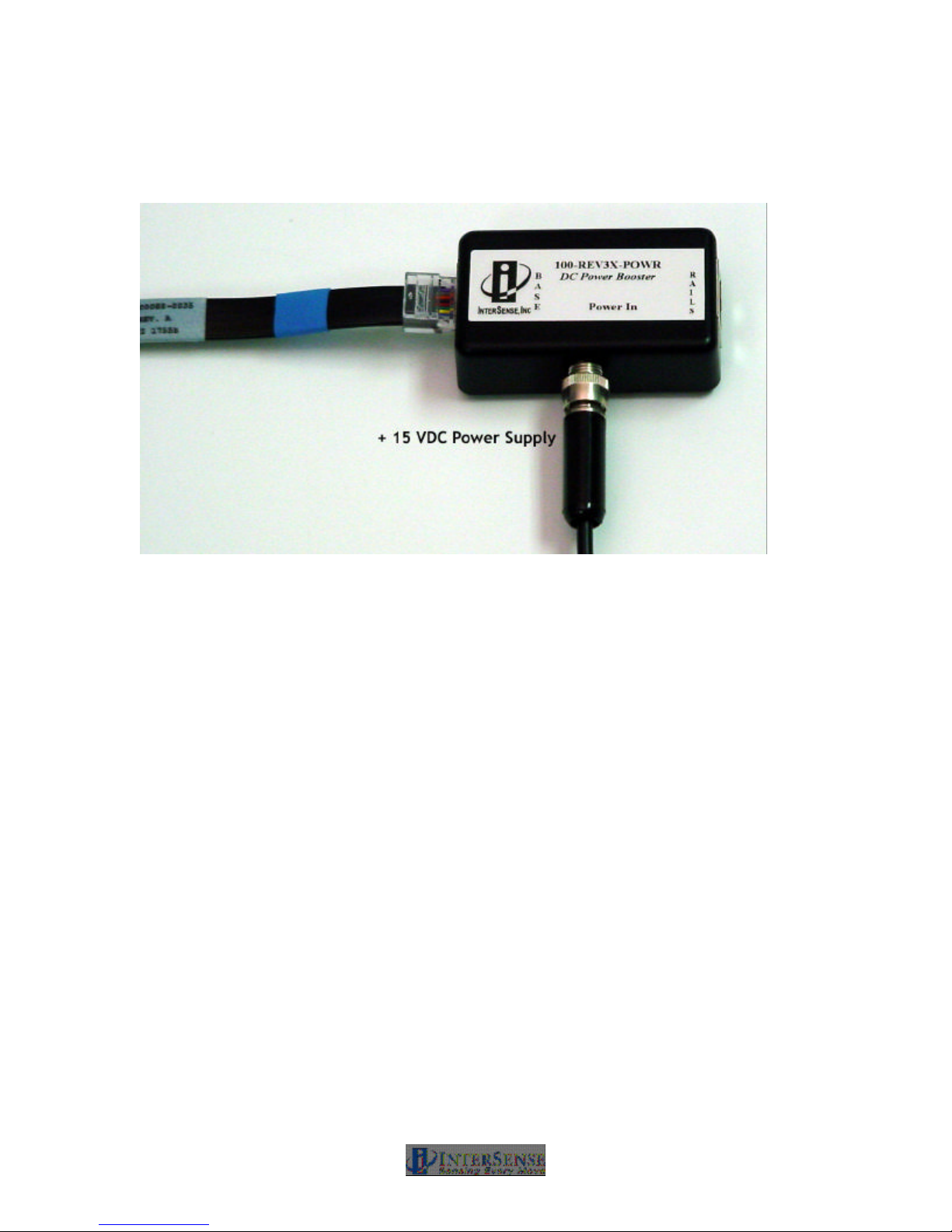
• Measurement ranges greater than 3 meters or,
• SoniStrip Arrays configured with greater than 12 SoniStrips where an additional power
booster is required after every 12th SoniStrip in a large SoniStrip Constellation Array.
Figure 21 - External Power Booster for SoniStrips
2. Setup your PC and launch ISDEMO
Follow the directions in Section 14 to install and run ISDEMO on a PC.
3. Connect the communications to the IS-900 system
Choose a communication option for connecting to the PC running ISDEMO. Section 14.3 details
the communication options for connecting with either serial or Ethernet.
3.6. Wireless MicroTrax Setup
Skip this step if you are using wired tracking devices.
IMPORTANT NOTE: Additional wireless IS-900 tracking systems in the immediate area should
be shut down while a new system is being configured to avoid the possibility of interference
during setup.
If you are using wireless devices, we recommend fully charging the Radio/Battery Modules prior
to use. If the power LED on the wireless Wand or Head tracker transmitter is flashing, that is an
indication of a low battery. Once the wireless receiver / transmitter combinations have been
configured below, each receiver will be matched to exactly one transmitter via an “RF Channel”
and “Link ID”. The system will not need to be configured again unless the user wishes to change
which receiver matches with which transmitter.
1. Make sure the IS-900 Processor is powered off.
IS-900 User Guide Page 47 of 159
Page 48

2. Plug the Base Receiver Modules into the IS-900 Processor.
Plug the cable coming from the Base Receiver Modules directly into one of the IS-900
Processor Ports (Ports 1 to 5 on the SimTracker processor or Ports 1 to 8 on the VETracker
processor) on the rear of the processor.
Turn on the wireless tracking devices by holding the power buttons for approximately 2 seconds.
• On the wireless wand, the power button is the button farthest to the left (under the
joystick).
• On the wireless head tracker, the power button is the only button available on the
transmitter pack that connects to the tracker itself.
3. Turn on the IS-900 processor. When the system has finished booting, verify that each
receiver has a green power LED lit. (If there are no LEDs on any of the receivers, then they
are not receiving power and they will not be configurable. Check that the cable was inserted
securely).
IS-900 User Guide Page 48 of 159
Page 49
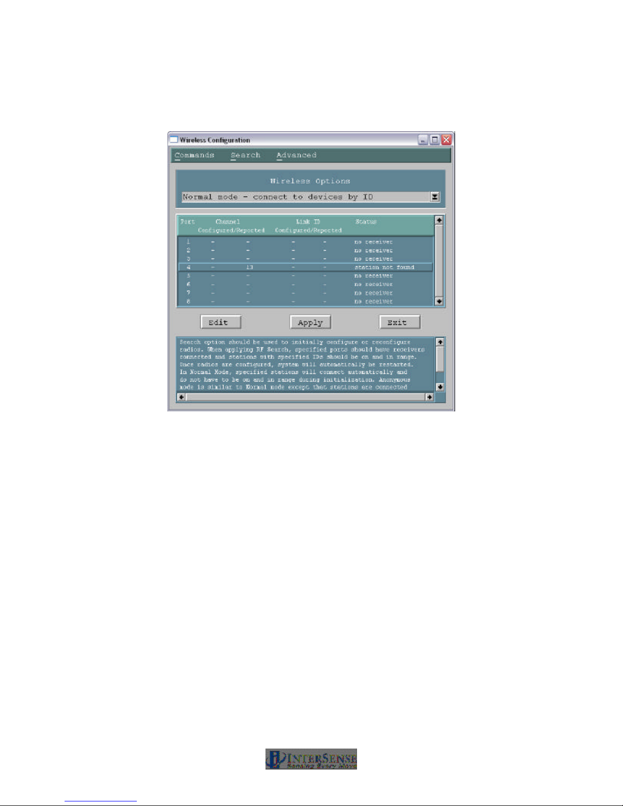
4. Run ISDEMO and connect to the processor via the “IS-900” configuration. Click
“Parameters->Wireless Configuration” from the menu. You will be presented with the
following dialog:
Port Port of the IS-900 Processor.
Configured Channel The channel that the connected receiver is configured to. No two
receivers can be configured to the same channel.
Reported Channel The channel that the connected receiver is currently on.
Configured Link ID The link ID that assigned to the receiver. Each wireless tracker has a
link ID associated with it when it is shipped. This 5 digit number can be
found on a label on your device.
Reported Link ID The link ID that is currently associated to the receiver.
Status Port status. Any ports with a status of “no receiver” do not have
receivers and cannot be configured
Steps 5-7 should be repeated for every receiver / transmitter combination in the system.
5. Click a row that corresponds with a receiver and click the “Edit” button. The following dialog
will be presented:
IS-900 User Guide Page 49 of 159
Page 50
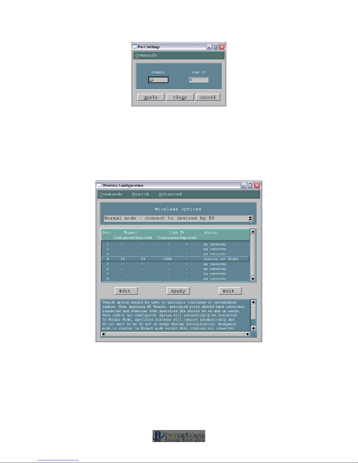
6. Enter a channel into the first input box. The valid range of channels is 0-15. Again, be aware
that no two receivers can use the same channel. For best results, it is recommended that
channels be configured such that they are separated by one unused channel. If multiple IS900 systems are in use in the same immediate area, verify that they are also set to different
channels.
7. The receiver will now be linked to a specific tracker via the “Link ID” input box. Enter the Link
ID of an appropriate device and click “Apply”. The wireless configuration dialog should now
look something like this:
8. Make sure that all configured transmitters are powered on and click the “Apply” button. It
may take a minute or two for the processor to apply the configuration. If the devices are
communicating properly, both green LEDs should now be lit on both the transmitters and
receivers. The status should also be listed as “ok”. If the status is “station not found” click
Search?RF Search.
IS-900 User Guide Page 50 of 159
Page 51
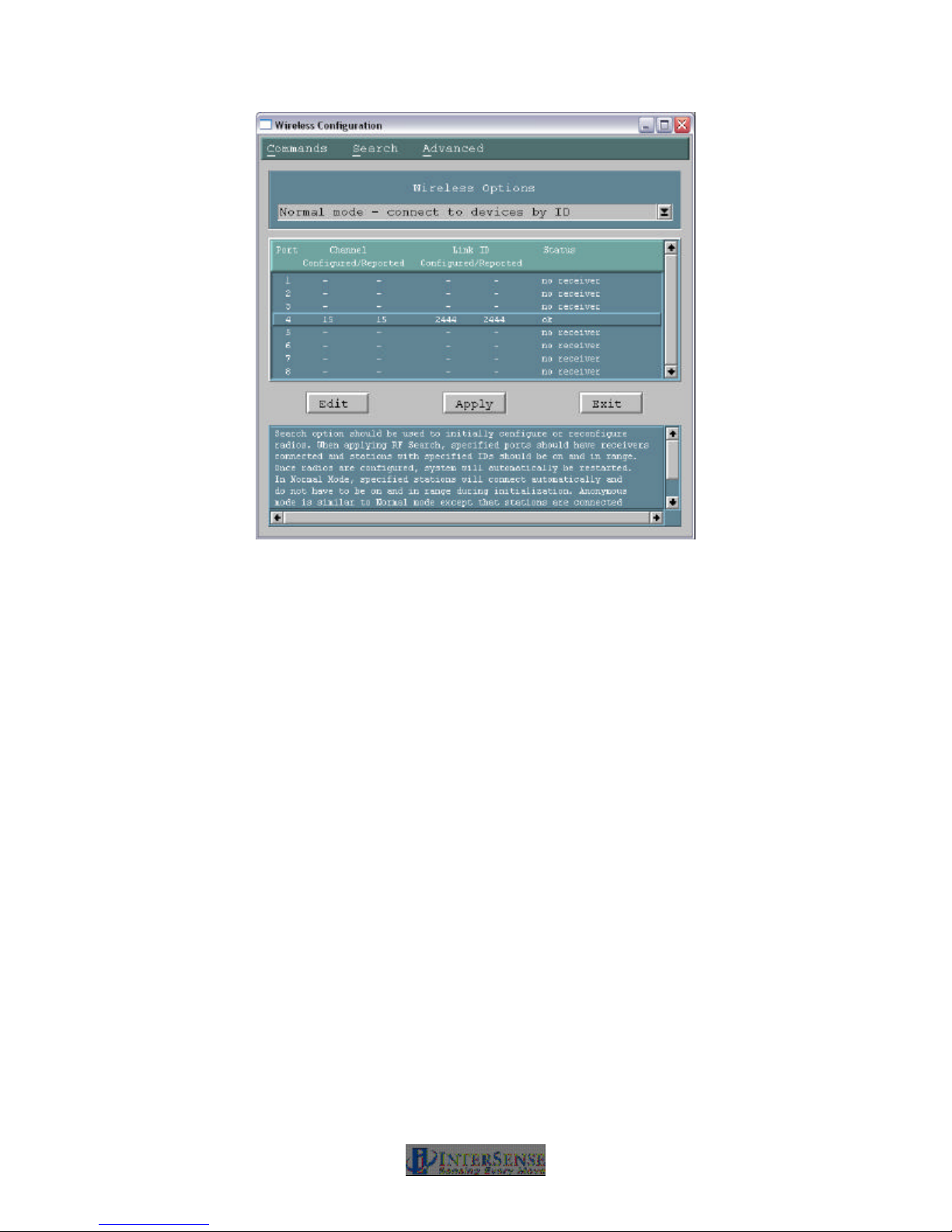
Helpful Tip: Placement of Wireless Base Receiver Module
You should not place the Base Receiver Module inside a metal container. If the IS-900 is in a
rack mount situation we recommend placing the adapters outside of the rack mount. In a typical
situation, the Base Receiver Module can be as far away as 100 feet from the Transmitter Module.
But if you are having an interference issue, you may want to move the Base Receiver Module
closer to the tracking area and try to insure line of sight. Extension cables are available to extend
the distance from the Base Receiver Module to the IS-900 Processor. You should keep the Base
Receiver Modules at least 10 cm (4 inches) apart from each other.
IS-900 User Guide Page 51 of 159
Page 52

Checking the installation
Make sure you have followed the steps in the Software and Hardware Setup sections.
1. Turn off the IS-900 Processor.
2. Turn the Wireless Transmitter Module.
3. The “Power” LED should be on. The “In Range” LED should be off. If the power LED is
flashing, the battery is low and you should charge it before you continue or replace the
battery with a charged one. If no LEDs come on you may need to charge the battery or
replace it with a charged one.
Note: If you turn the Wireless Transmitter Module ON but do not move it for more than 10 minutes
it will go into sleep mode and you will have to switch the power ON again.
4. Turn on the power to the IS-900 processor. The LEDs on the front panel next to each port
should come on and then stay on for each occupied port. The “Power” LED on the Base
Receiver Module should turn on. In less than 10 seconds after the Power LED comes on, the
Base Receiver Module red LED should turn on and the Wireless Transmitter Module
“Connection Status” LED should also come on.
If any of these steps failed or if the LCD on the front panel of the IS-900 processor indicates X for
the wireless station, refer to the Troubleshooting section in this manual.
5. Place the MicroTrax device(s) under the IS-900 SoniStrip Constellation Grid. The LCD on
the front panel of the IS900 Processor should show a T for each station indicating it is
tracking. If it indicates L (lost), then you need to confirm that MicroTrax is within the tracking
volume and the SoniStrip Constellation has been properly set up on the IS-900 Processor
using ISDEMO. If you are unable to get the tracker to work properly please contact Technical
Support using the information in the Contact section of this manual.
3.7. Loading the Constellation File
1. Open the Configuration Script window in ISDEMO
Under the Tools menu in ISDEMO, click on Configuration Script (Figure 22) to open the
Configuration Script window.
IS-900 User Guide Page 52 of 159
Page 53
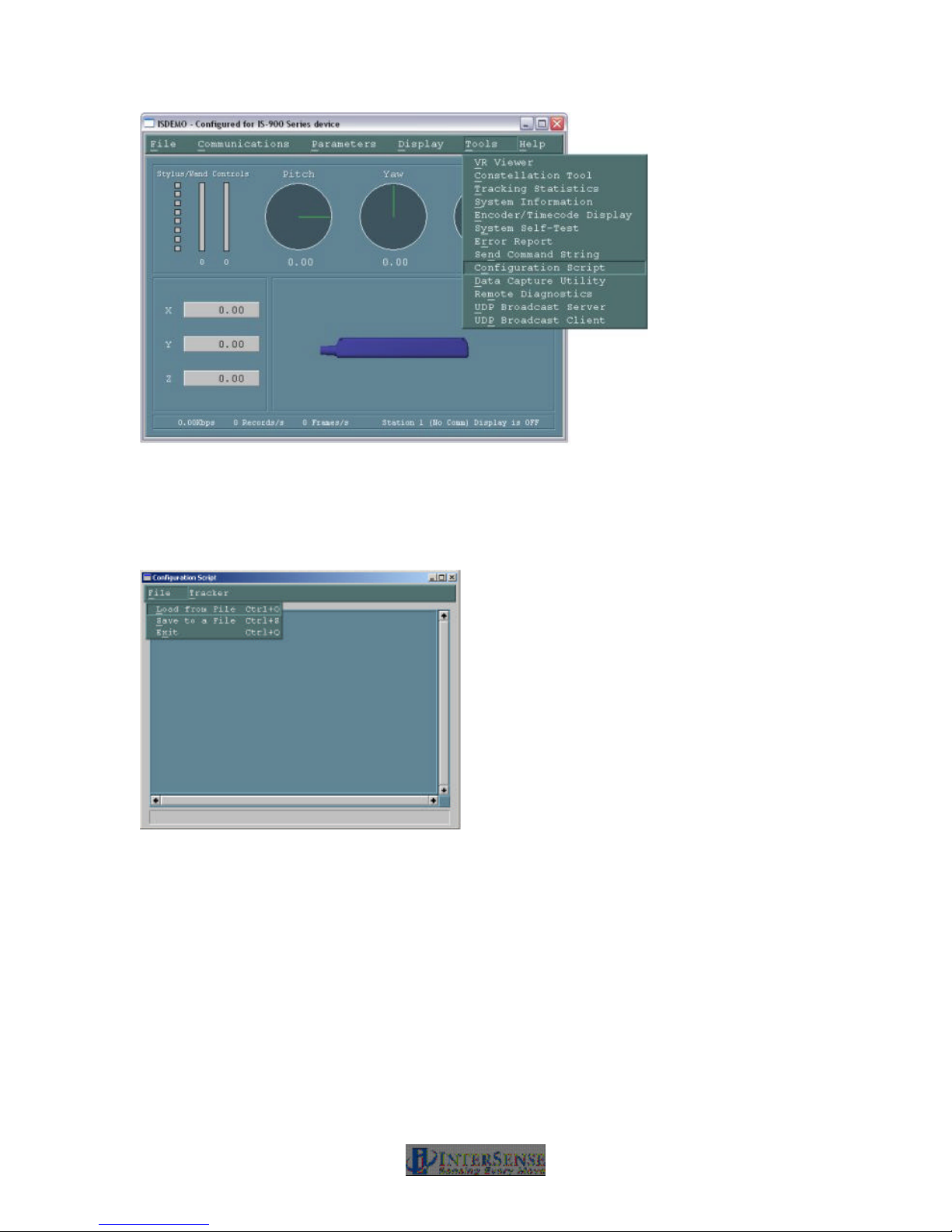
Figure 22 - Configuration Script Menu for loading SoniStrip Constellation array file
From the Configuration Script window under File menu, select Load from File (Figure 23).
Locate the SoniStrip Constellation Array .txt file created in Step 3.4 above. Double click on the
file and click on OK.
Figure 23 - Configuration Script File Menu
IS-900 User Guide Page 53 of 159
Page 54
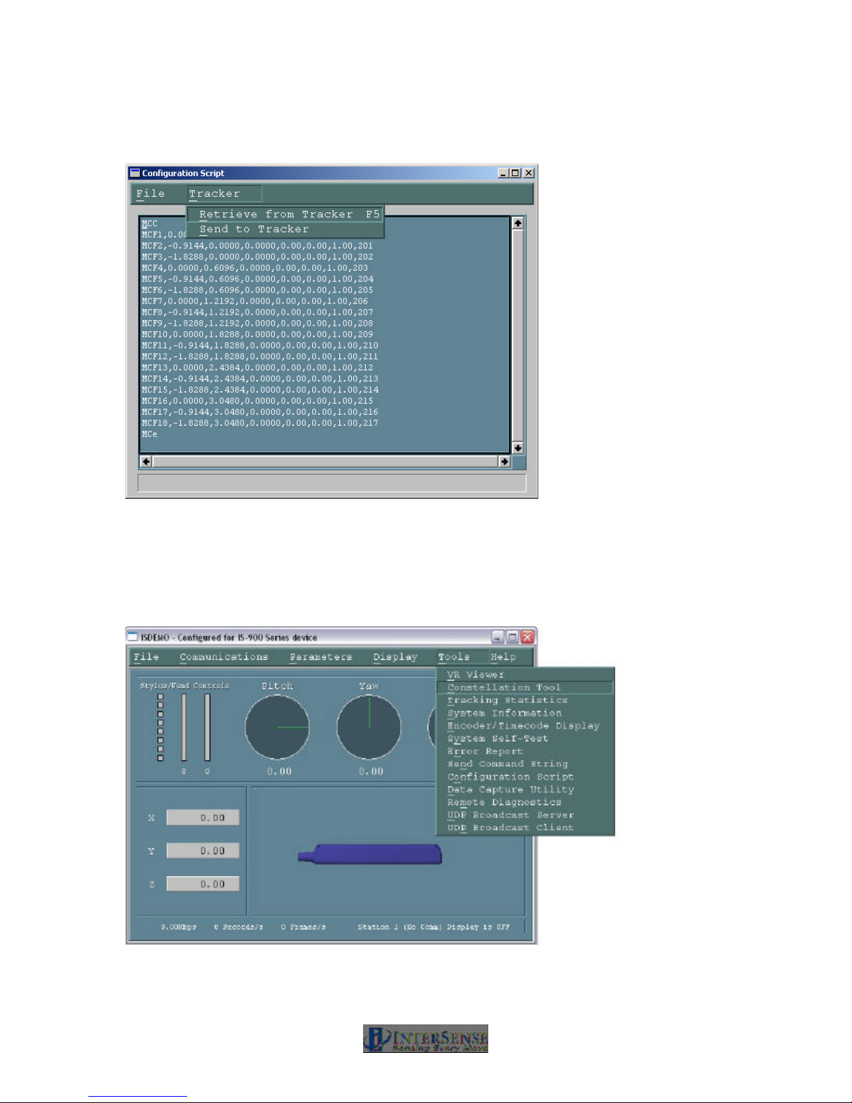
From the Configuration Script window under Tracker menu, select Send to Tracker (Figure 24).
The SoniStrip Constellation Array is now downloaded into the IS-900 Processor.
Figure 24 - Sending Configuration Script to Tracker
2. Check the Configuration
To check the configuration, open the Constellation Configuration Tool window by selecting
Tools? Constellation Tool from the Tools menu in the main window of ISDEMO (Figure 25).
Figure 25 - Constellation Tool Selection
IS-900 User Guide Page 54 of 159
Page 55
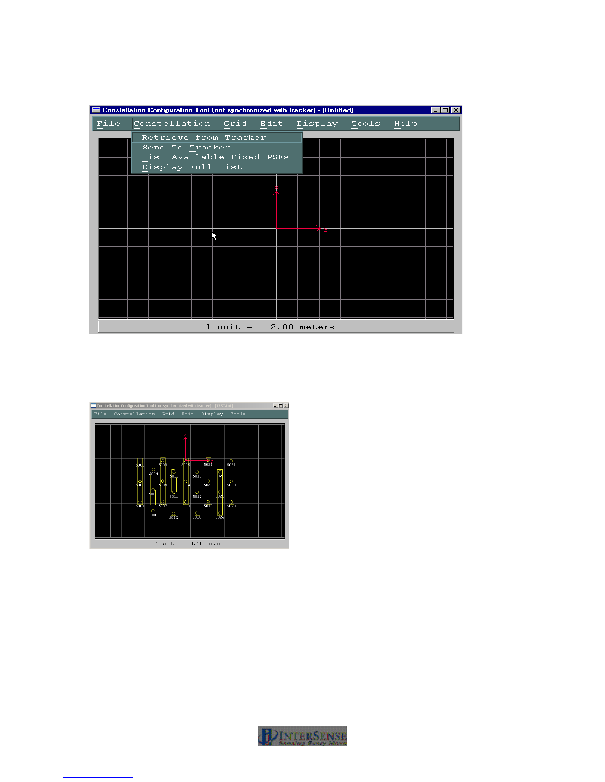
3. From the Constellation Configuration Tool window, select Retrieve from Tracker from the
menu item Constellation (Figure 26).
Figure 26 - Checking installed SoniStrip Constellation Array
This will upload the grid into the Constellation Configuration Tool window from the IS-900
Processor. At this point, you should see SoniStrip Constellation Arrays similar to examples
covered in Section 3.3 for typical configurations (Figure 27, Figure 28, and Figure 29).
Figure 27 - ISDEMO Constellation Tool Screen for Ceiling Mount Power Wall Applications
IS-900 User Guide Page 55 of 159
Page 56
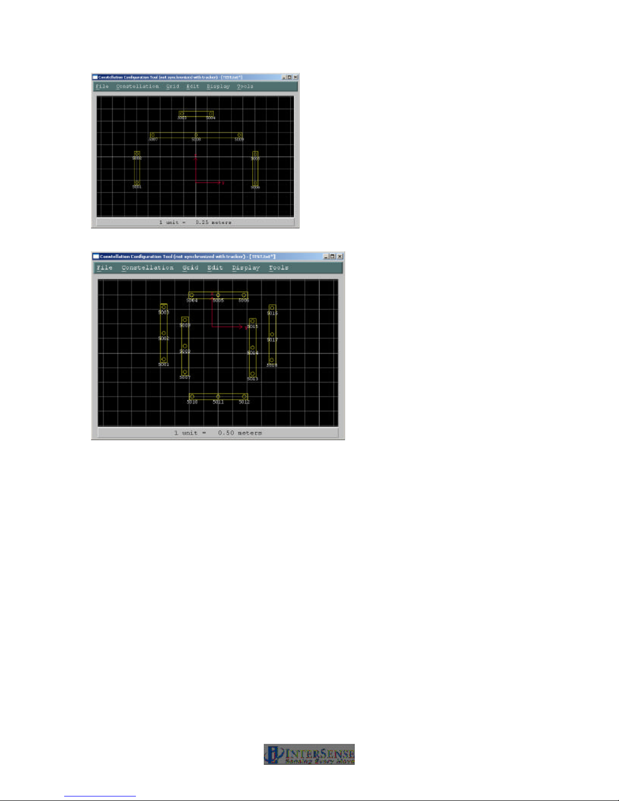
Figure 28 - ISDEMO Constellation Tool Screen for Wall Mount Power Wall Applications
Figure 29 - ISDEMO Constellation Tool Screen for CAVE-like Applications
4. Verify system is tracking
While still in the Constellation Configuration Tool window, type CNTL-D (or select menu item
Display? Start Displaying Data as shown in Figure 30) to verify the Constellation Array is
correctly installed and the system is tracking. The tracked device will appear green in the center
of the display window indicating correct tracking. Move the physical tracker around and see it
move in the display window.
IS-900 User Guide Page 56 of 159
Page 57
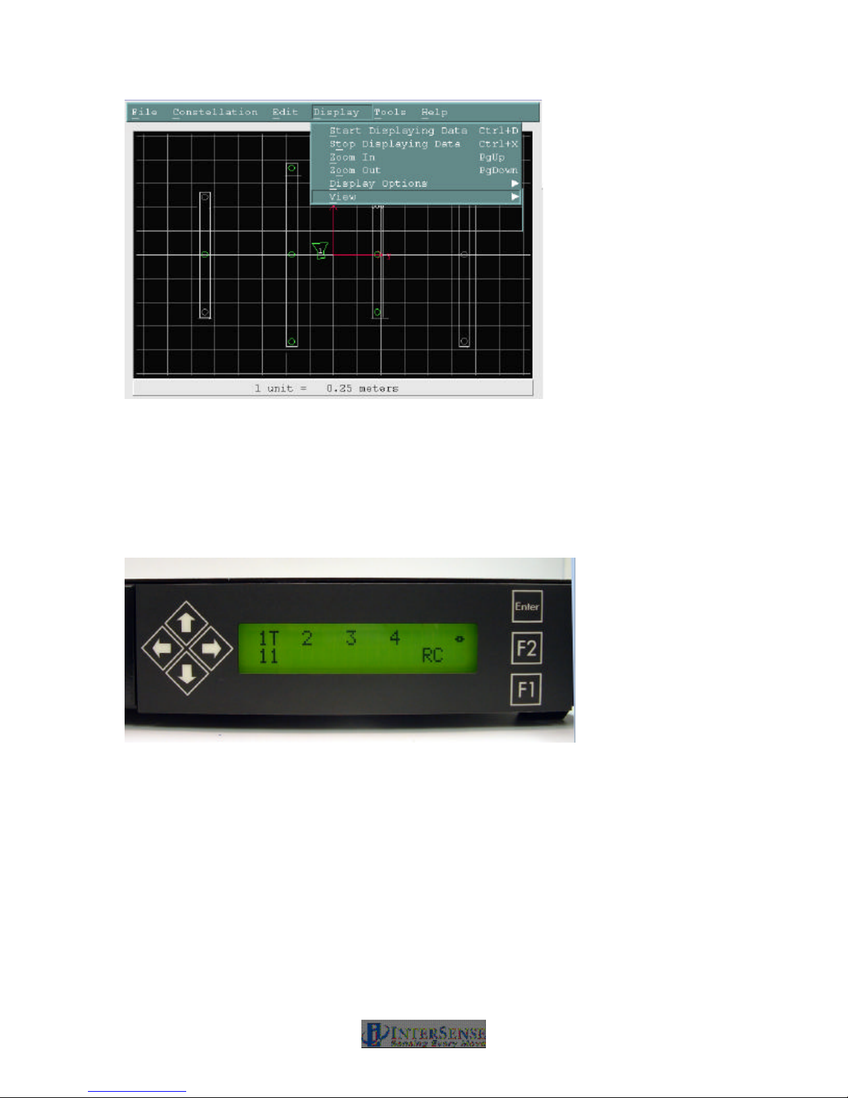
Figure 30 - ISDEMO Constellation Tool Screen with Tracking Device
Also check the LCD panel of the IS-900 Processor. For each connected tracking station, “T”
should appear on the IS-900 Processor’s front LCD panel to indicate proper tracking (Figure 31).
If an “X”, appears you may not have properly saved or loaded in the SoniStrip Constellation
Array. The “X” could also indicate hardware, cabling or wireless link issues. Go back to Steps 5
& 6 to reload the proper configuration script containing the correct Constellation Configuration
Array. Refer to Section 11 for troubleshooting hardware, cabling and wireless connectivity
issues.
Figure 31 - Tracking Status Display on IS-900 LCD Panel
5. Saving the Configuration
Save the current settings into firmware of the IS-900 Processor by selecting the menu item File?
Save Current Settings from the main ISDEMO (Figure 32). A window will come up asking to
save into permanent memory. Select YES to save into permanent memory.
IS-900 User Guide Page 57 of 159
Page 58
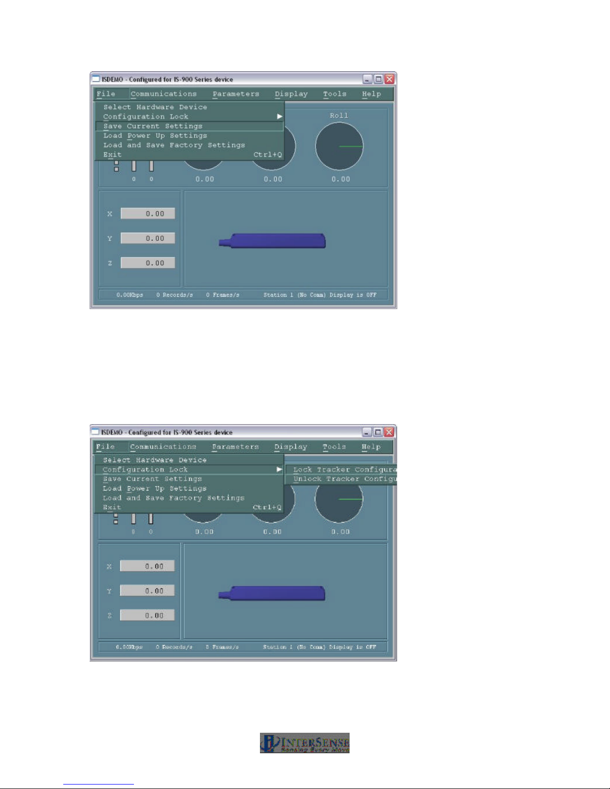
Figure 32 - Saving All Configuration Settings to IS-900 Processor
6. Locking the configuration
Locking the settings will prevent inadvertently changing settings when not desired. Lock the
settings by selecting menu item File? Configuration Lock in main ISDEMO window (Figure 33).
A window will come up asking to Lock tracker configuration. Click on Lock Tracker Configuration.
Figure 33 - Locking Configuration Settings in IS-900 Processor
IS-900 User Guide Page 58 of 159
Page 59

7. Connecting to application
Follow the instructions or manual that came with the tracked application for using the IS-900
tracking system. If you have problems connecting to your application, first contact the application
developer for detailed information about connecting to InterSense tracking systems. If you still
need assistance, contact InterSense for technical support.
The IS-900 CD delivered with this system contains InterSense Software Development Kit (SDK)
for developing interfaces specific to new applications. The application programmers interface
(API) and library calls to the InterSense libraries are documented in Section 16.
3.8. Using Wireless MicroTrax Devices
When power is powered on, the Transmitter Module “Power” LED will turn on. When the battery
voltage gets to a low level, the Transmitter Module “Power” LED will begin to flash. This indicates
the devices should have about an hour of tracking left before the charger must be plugged in for it
to work.
If the MicroTrax Transmitter establishes communication with the Receiver, then the “In Range”
LED on the Transmitter will light and remain on as long as the device in either “In range” or not in
sleep mode.
Sleep Mode: If no motion is detected by the Transmitter for about 10 minutes, it and the
MicroTrax will power down and the LEDs will turn off. Once the transmitter has shut itself off, it
must be manually powered on again before it can be used.
NOTE: While the Wireless Transmitter Module is turned off or out of range, the IS-900 Processor
will show an X in the LCD and the IS-900 trackers’ output of position and orientation will remain
fixed at their last value.
Summary of LEDs on Wireless Transmitter Module
Power:
ON – The MicroTrax and wireless Transmitter have power.
OFF – If the Power Switch is on may mean the battery is too low to operate the device.
FLASHING – The battery is low.
Connection Status:
OFF – If the Power LED is on, no connection has been made to a Base Receiver.
ON – The Transmitter is connected to a Base Receiver Module.
FLASHING – Device is losing communication.
Summary of LEDs on Base Receiver Module
Power:
ON – Base Receiver Module has power from IS-900 Processor
OFF – IS-900 is off or is not supplying power to this port.
Connection Status:
ON – The Receiver is communicating (or attempting to communicate) with a
Wireless Transmitter Module.
IS-900 User Guide Page 59 of 159
Page 60

OFF – A connection has not been established with a Wireless Transmitter Module.
Charging Instructions
Only use the power supply from InterSense when charging the Radio/Battery
board. Other chargers could cause failures. See the battery handling
instructions at the beginning of this manual.
When the “Low Power” LED on the Transmitter Module is ON or when you want to make sure
that the module is fully charged, you should connect the Transmitter Module to the charger. You
may leave the Transmitter Module on while charging; but, if you plan on using another
Transmitter Module– Base Receiver Module pair with the same channel selected, you must turn
off the Wireless Transmitter Module while it is being charged.
While it is charging the LED next to the charger port will be on (Orange). When it turns solid
Green, the battery is finished charging (flashing green indicated that the battery is being “topped
off”. A fully discharged battery takes less than 4 hours to charge. If the green charging LED does
not turn off after 6 hours, there may be a problem. Please disconnect the charger and contact
technical support.
Changing a MicroTrax head tracking device from a wireless to wired configuration
To convert the MicroTrax devices from wireless to wired mode, follow these steps:
1. Turn off the IS-900 processor
2. Disconnect the appropriate receiver cable from the IS-900 Processor to the Base Receiver
Module.
3. Turn off the power on the Wireless Transmitter Module connected to the MicroTrax device.
4. Unplug the MicroTrax device from the Transmitter Module and plug it into the MicroTrax IS-
900 Wired Adapter device.
5. Connect the wired adapter in the IS-900 Processor and turn the power on. No software or
configuration will need to be changed.
IS-900 User Guide Page 60 of 159
Page 61

8. Interface Communication Protocol
For firmware version 4.20 or higher
Terminology
Throughout this section and the ISDEMO program described in Section 14, certain terms and
acronyms are used to reference functional components of all InterSense tracking systems.
Specifically, IS-900 models contain an ultrasonic subsystem that includes SoniDiscs (Ultrasonic
Transponder Beacons) and Microphones (Ultrasonic Receiver Modules – URMs). To generalize
the interface protocol and configuration tools for these tracker models, InterSense uses the term:
PSE - Position Sensing Element.
A PSE may be Mobile or Fixed. Mobile PSEs are assigned to the stations and their movements
are tracked by the system (i.e. MicroTrax Microphones). Fixed PSEs form a CONSTELLATION?
that is used as a reference for tracking (i.e. SoniStrips & SoniDiscs). In the case of IS-900
tracking systems, Microphones are mobile and SoniDiscs are fixed.
8.1. Commands Sent from the Host to the Tracker
<> Carriage return line feed pair- not needed for single character commands.
CR – ASCII value 13, LF – ASCII value 10.
{} List of parameters required for command.
[] List of optional parameters for command. Omitting those results in a query.
The IS-900 emulates most (but not all) of the commands in the Polhemus Fastrak™ protocol,
thus it is possible to use the IS-900 with most applications without writing new driver code. There
are also several additional commands added to access some of the advanced features of the IS900 that do not have any counterpart in the Fastrak™ protocol.
Note:
Firmware version 3.xx extended Fastrak™ protocol to support up to 32 stations (actual number
allowed is determined by your hardware configuration). StationNum in commands, status and
data records is now encoded in an extended hexadecimal notation. Numbers 1 to F conform to
standard hexadecimal notation, with numbers greater that F represented by additional upper case
letters of the alphabet. For example, number 16 is displayed as G.
8.2. Standard Fastrak™ Interface Commands
Data Record Request P Request a data record from all active stations.
Only used in polled mode.
Output mode C Put in continuous output mode.
Default Polled mode
Alignment Reference Frame
IS-900 User Guide Page 61 of 159
c Put in polled output mode.
A{stationNum},[Ox,Oy,Oz,Xx,Xy,Xz,Yx,Yy,Yz]<>
Page 62

Sets the coordinate frame with respect to which outputs for
that station will be reported. The coordinate frame is
defined by a set of three points. Ox,Oy,Oz defines the
origin of the new coordinate system, Xx,Xy,Xz defines a
point on the positive x-axis and Yx,Yy,Yz defines a point
on the positive y-axis. The effect of this command is
incremental, or relative to any current alignment reference
frame already in place. If optional parameters are omitted,
current values are returned. Units are centimeters.
Default Fusion Mode: X=North, Y=East, Z=Down,
Reset Alignment Reference Frame
R{stationNum}<>
Resets reference frame to the default.
Boresight Reference Angles
G{stationNum},[yawref, pitchref, rollref]<>
Sets the boresight reference angles for the specified
station. If set, these values are then used by the next
Boresight command instead of current orientation. If
optional parameters are omitted, current reference angles
are returned. Units are degrees.
position origin is defined by
SoniStrip Constellation Array
horizontally leveled. See
Section 3.1.
Default 0,0,0
Boresight Compatibility Mode
MBF<> Switch system to Fastrak Compatible mode.
MBI<> Switch system to Firmware Version 2.x Compatible
mode.
In firmware versions prior to 3.00 the B{stationNum}<>
command was implemented as the Heading Boresight (see
below) and full boresight was not available. To maintain
compatibility with the user software written at that time, two
Boresight Compatibility modes are available. In Fastrak
Compatible mode B{stationNum}<> command executes full
3-DOF boresight and MB{stationNum}<> effects heading
only. In the Firmware Version 2.x Compatible mode the
meanings of these commands are reversed.
Default Firmware Version 2.x Compatible, MBI<>
IS-900 User Guide Page 62 of 159
Page 63

Boresight B{stationNum}<> (Fastrak compatibility mode)
MB{stationNum}<> (Firmware Version 2.x compatibility
mode)
Boresight a station. If boresight reference angles have
been specified by the G{stationNum}[yawref, pitchref,
rollref]<> command prior to issuing of Boresight command
then that orientation becomes the new reference point.
The angles output by the tracker at that orientation
become zero. Otherwise, system uses current station
orientation and that becomes the new reference line of
sight. Please make sure that the object being tracked (like
an HMD) is leveled and is pointing down the x-axis when
boresighting a station.
Unboresight b{stationNum} <> (Fastrak compatibility mode)
Mb{stationNum}<> (Firmware Version 2.x compatibility
mode)
Unboresight a station. Reference angles are cleared for
the specified station.
Heading Boresight B{stationNum}<> (Firmware Version 2.x compatibility
mode)
MB{stationNum}<> (Fastrak compatibility mode)
This command has no effect with the IS-900.
Heading Unboresight b{stationNum}<> (Firmware Version 2.x compatibility
mode)
Mb{stationNum}<> (Fastrak compatibility mode)
This command has no effect with the IS-900.
Set Serial Communication Parameters
o{rate,parity,bits,HHS}<> Change the serial
communication parameters
rate is one of 3,12,24,48,96,192,384,576,1152
(rate is multiplied by 100)
parity N = none
O = odd
E = even
bits 7 or 8
HHS (Hardware handshake)
0 = OFF
1 = ON
Default serial communications settings:
Baud 1152
IS-900 User Guide Page 63 of 159
Page 64

Parity N
bits 8
HHS OFF
System Record Request S Request a system status record to be sent.
Station Status l{stationNum},[state]<> Set the stationNum on or off.
state 0 = OFF, 1 = ON
Default All connected stations are on
Output Units Control U Sets output data record position units to inches.
u Sets the position units to centimeters. These only
matter in 6-DOF mode.
Default U
System control ^K Save the current settings to nonvolatile memory.
W Restore the system settings to the factory
defaults.
^Y Restart the firmware to the power up condition.
^S Suspend data transmission.
^Q Resume data transmission.
Caution: Sending W command will cause all the user
configuration information to be lost.
Output record mode F Put in ASCII output mode
f Put in Binary output mode.
Default F
IS-900 User Guide Page 64 of 159
Page 65
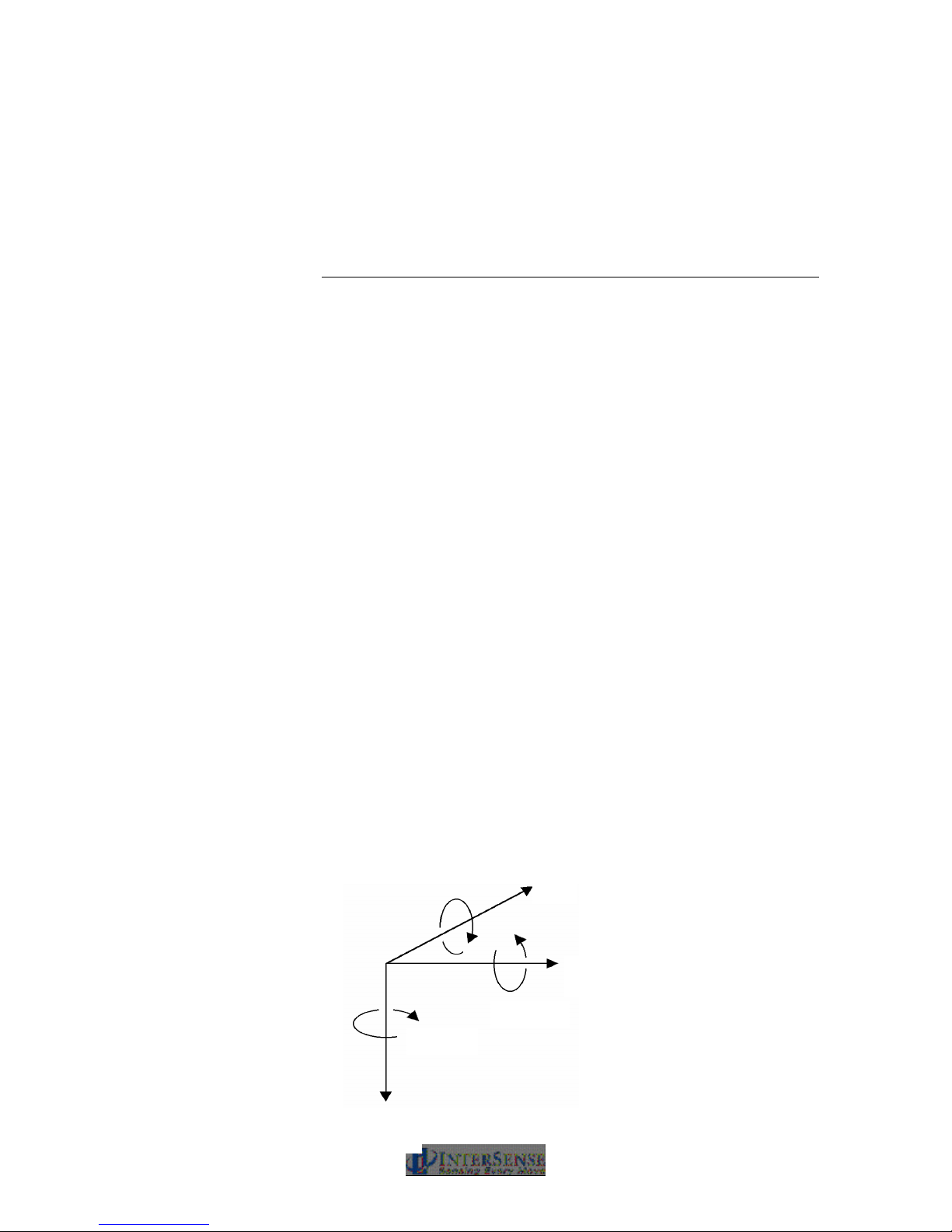
Output record list settings O{stationNum},[p1],[p2],[p3],.....,[pn]<>
1 byte (ASCII or binary)
Yaw Roll Pitch
Sets the output data list for stationNum. If optional
parameters are omitted, a data record containing current
output list settings for the station is returned.
Item Description Output Format
0 ASCII space character 1 ASCII byte
1 ASCII CR, LF pair 2 ASCII bytes
2 x, y, z position coordinates 3 floats
4 yaw, pitch and roll Euler
angles
5 X-axis direction cosines 3 floats
6 Y-axis direction cosines 3 floats
7 Z-axis direction cosines 3 floats
11 orientation quaternion 4 floats
16 stylus switch status (always 0)
18 x, y, z in 16 bit binary format see below
19 yaw, pitch and roll in 16 bit
binary format
20 quaternion in 16 bit binary
format
21 time stamp, in selected time
units
22 buttons see below
23 joystick see below
40 tracking status 0-255
68 – 71 auxiliary inputs
75 communication integrity 0-100
Default 2,4,1
Data Item 4 – Euler Angles.
The Euler angles are defined as rotations about Z, then Y,
then X in body frame. Angles are returned in degrees
3 floats
see below
see below
see section 5.3.1
IS-900 User Guide Page 65 of 159
X
Y
Z
Page 66

2
Data Items 5, 6, 7 – Direction Cosines.
X-axis, Y-axis and Z-axis direction cosines can be used to
construct a 3x3 rotation matrix.
X direction cosines.
x1 x2 x3
Y direction cosines.
y1 y2 y3
Z direction cosines.
z1 z2 z3
This matrix can also be constructed from Euler angles:
cos(P)*cos(Y) sin(R)*sin(P)*cos(Y) - cos(R)*sin(Y) cos(R)*sin(P)*cos(Y) + sin(R)*sin(Y)
cos(P)*sin(Y) sin(R)*sin(P)*sin(Y) + cos(R)*cos(Y) cos(R)*sin(P)*sin(Y) - sin(R)*cos(Y)
-sin(P) cos(P)*sin(R) cos(P)*cos(R)
Data Item 11 – Orientation Quaternion.
Quaternion is returned as q = [w, x, y, z]. Quaternion to
rotation matrix conversion can be accomplished using the
following formula:
1–2y2 – 2z2 2xy – 2wz 2xz + 2wy
2xy + 2wz 1 – 2x2 – 2z2 2yz – 2wx
2xz – 2wy 2yz + 2wx 1 – 2x2 –
Data Items 18, 19, 20 – 16 bit binary format.
16 bit binary format can be used in applications requiring
fastest possible serial I/O. Each floating point number is
stored in 2 bytes with only 14 bits containing actual data.
This results in lower accuracy than the standard IEEE
floating point format.
Data is 2’s-complement. The first byte of the data set has
its high-order bit set to 1; all others have them set to zero.
This can be used for data synchronization. Data is
returned low-order byte, then high-order byte. Use
following code sample as an example on how to decode
this format:
IS-900 User Guide Page 66 of 159
Page 67
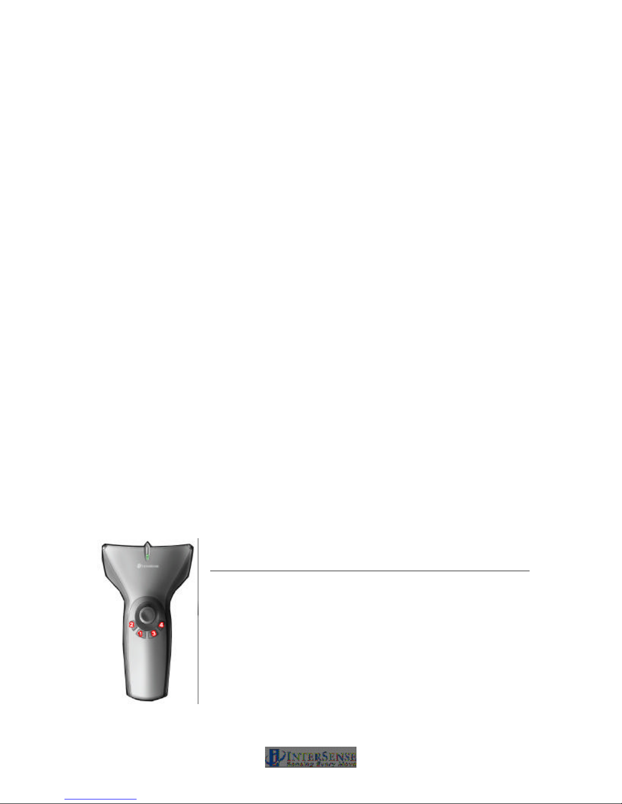
To decode position:
lo = (dataRecord[3] & 0x007F);
hi = (dataRecord[4] & 0x007F);
int14bit = (lo « 2) | (hi « 9);
result = (float) int14bit * 3.0 / 32768.0;
Result is a number representing position (in meters) and has a
full range of ± 3.0 meters (−300.0 to+299.963 centimeters or –
118.110 to 118.096 inches).
To decode Euler angles:
lo = (dataRecord[3] & 0x007F);
hi = (dataRecord[4] & 0x007F);
int14bit = (lo « 2) | (hi « 9);
result = (float) int14bit * 180.0 / 32768.0;
Resulting number represents orientation and has a full range of
± 180.0 (−180.0 to +179.978) degrees.
To decode Orientation Quaternion:
lo = (dataRecord[3] & 0x007F);
hi = (dataRecord[4] & 0x007F);
int14bit = (lo « 2) | (hi « 9);
result = (float) int14bit * 1.0 / 32768.0;
Resulting quaternion value has range of ± 1.0.
Data Item 22 – Buttons.
One 3-digit integer in ASCII format or one byte in binary format.
Bits represent the button states of a station’s buttons. If a button
is pressed, the corresponding bit is 1 otherwise it is 0. The bit
assignments for the wand are (where bit 0 is the least significant
bit):
Bit Button MicroTrax Wand button
0 1 1 on wand image
1 2 2 on wand image
2 3 3 on wand image
3 4 4 on wand image
4 5 center (press joystick)
5 6 trigger
IS-900 User Guide Page 67 of 159
Page 68
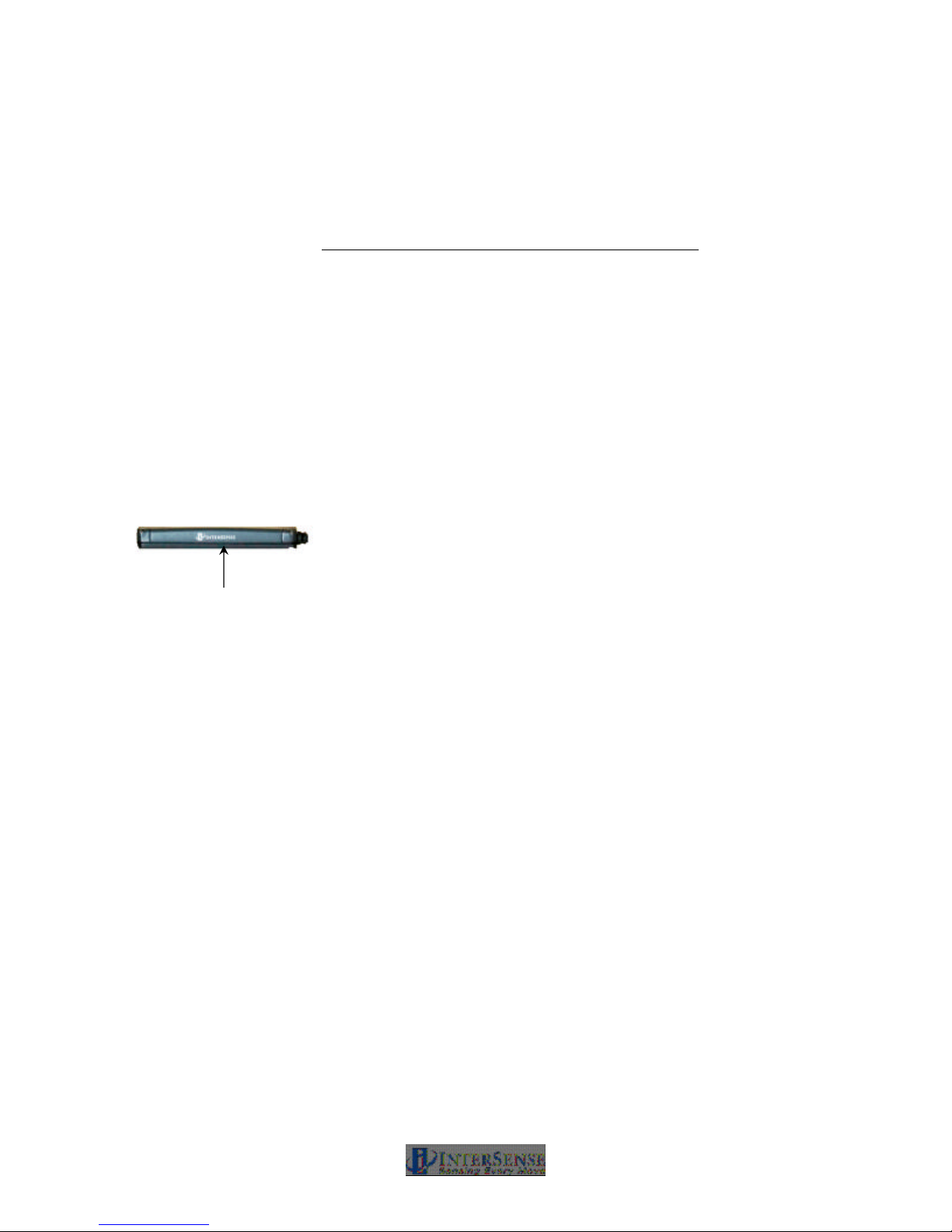
Data Item 23 – Joystick.
Two integers, one for each axis, values ranging from 0 to 255.
Two 3-digit integers in ASCII format or two 1-byte unsigned
values in binary format. Values at limits and at center are:
Axis Position Value
left/right (1st integer) left 0
center 127
right 255
front/rear (2nd integer) rear 0
center 127
front 255
Define Tip Offsets N{stationNum},[Ox, Oy, Oz]<>
By default, the point being tracked is for each station is:
Wand Station: Tip.
Head Tracking Station: Intersection of front surface,
bottom surface and at mid length, see image to the left.
Tip Offset: intersection of
front surface and bottom
surface and at mid
length.
This command allows the user to define a set of position
offsets, so a different point can be tracked. Offsets are
measured in the body coordinate frame of the MicroTrax
station and are entered in centimeters. If optional
parameters are omitted, current settings are returned.
Default 0,0,0
Position Operational Envelope
V{stationNum},[Xmax, Ymax, Zmax, Xmin, Ymin, Zmin]<>
This command sets the boundaries of the area where
position is to be tracked. Whenever a station leaves the
defined range, position tracking is stopped and only
resumed once it is back within the defined boundaries.
Parameters are entered in meters. If optional parameters
are omitted, current settings are returned. Units are
meters.
Default 200,200,200,-200,-200,-200
IS-900 User Guide Page 68 of 159
Page 69

8.3. Fastrak™ Commands Implemented for Compatibility
Hemisphere H{stationNum},[p1,p2,p3]<>
Sets the tracking hemisphere for a magnetic tracking
system. Because InterSense trackers are not magnetic
the parameters are ignored. However, they can be set and
then queried for compatibility with software such as
MultiGen SmartScene or Immersion Corporation haptic
Software. If optional parameters are omitted, a data record
containing current Hemisphere settings for the station is
returned.
Default 1,0,0
8.4. InterSense specific Commands
All InterSense specific commands start with the letter M (for “Manufacturer-specific”) and must be
completed by a CR,LF pair.
8.4.1. System Configuration Commands
Time Units The time stamp recorded is the time when the tracker data
was collected from the hardware. The time index is set to
zero when tracker is first turned on.
MT<> Sets the units for the data record time stamp to
milliseconds.
Mt<> Sets the units for the data record time stamp to
microseconds.
Default T
Set Current Time to Zero MZ<> This command sets current time index of the
tracker to zero.
IS-900 User Guide Page 69 of 159
Page 70

Set Ethernet Communication Parameters
MEthIp[address]<> Sets System IP address.
Use dotted format like 192.168.1.1. If address is omitted,
the current address is returned, 31EI[address]<>. The IP
address takes effect immediately unless an address was
already set, in which case system settings must be saved
and the system must be restarted.
MEthUdp[state]<> Sets state of UDP broadcast.
state=1 to enable, state=2 to disable (default).
MEthUdpPort[port]<> Sets UDP broadcast port.
Default Ethernet communications settings:
UDP state OFF
UDP port 5001
IP address None
InterSense System Status Record Request
MS<> Request the manufacturer-specific system status
record. This is information about parameters which
are specific to the InterSense product, additional to
the standard system status information obtained
using the S command.
Tracking Status Record Request
MP<> Requests tracking status information for all 12
stations. See Section 5.5.5 for the description.
Ultrasonic Timeout Interval
MU[interval]<> This command has no effect with the IS-
900.
Default N/A
Ultrasonic Receiver Sensitivity
Mg[Level]<> This command has no effect with the IS-900.
Default N/A
IS-900 User Guide Page 70 of 159
Page 71

Genlock Synchronization MG[State, Rate]<>
State 0 – Genlock is off
1 – Reserved
2 – External sync, manual (supply strobe rate)
3 – Internal sync, supply output record rate
Rate Value in Hertz used with State = 2 and 3
Default 0
Genlock Phase MGP[Param]<>
Param can be the Phase (0 to 100%) or ‘+’ to increase to
the next phase point, or ‘-‘ to decrease to the next phase
point. Please see Appendix F for complete details.
Default 0
Genlock Sync Source MGS[source]<>
source 1 – TTL
2 – NTSC
Configuration Lock Configuration lock commands are used to prevent unintentional
changes to tracker configuration. Two Levels of protection are
provided. The First prevents changes to saved settings. The
second prevents changes to current unsaved (session) settings as
well as saved settings.
MConfigLockMode[mode]<>
Mode
0 Lock off
1 Lock saved settings
2 Lock saved and session settings
Default 0
In mode 1 (lock saved settings), the Fastrak commands to
save current (^K) and restore factory (W) settings are
disabled. In mode 2 (lock saved and session settings), the
Fastrak command to restore saved settings (^Y) is
disabled as well as ^K and W. In mode 0 (lock off), ^Y, ^K
and W are all enabled. When mode is changed, it is saved
to nonvolatile memory without affecting any other saved
settings. If mode is omitted, the current setting is returned.
The LCD menu options to save and restore settings are
not affected by lock mode.
IS-900 User Guide Page 71 of 159
Page 72

SoniStrip LED control ML[state]<>
If state is 0, the blue LEDs on the SoniStrips are disabled. Visual
confirmation of the operation of the ultrasonic system is important,
so don’t disable the LEDs unless they interfere with your
application.
Default 1
Beacon Scheduler MSchAlg[n]<>
Selects beacon Scheduling Algorithm. If n is 1, a distance-based
algorithm is used. This algorithm chooses beacons based on
distance only. If n is 2 a directional algorithm is used which
chooses beacons based on orientation as well as distance.
Default 2
Error reporting Hardware and configuration errors are stored internally and can
be reported to the application. If the application is not setup to
accept error messages, or if you are not sure, error reporting
should be disabled. This setting is not saved with tracker
configuration, so error reporting is off every time tracker is turned
on.
ME<> Returns all errors, one per error message.
MEC<> Clear all errors from internal list.
ME1<> Enable error reporting.
ME0<> Disable error reporting.
Default Error reporting is OFF
Command logging Command logging captures all host commands into a file
for debugging purposes. The log file holds a maximum of
500 kB. When the max size is reached, the file is rewound
and overwritten with new entries. Long series of P and MP
commands are abbreviated to save space. The command
logging state is also indicated on the LCD (see Section 9).
Command logging control is available on the LCD menu
under System ConfigàCommand Log: Enable Log,
Disable Log and Clear Log. It is accessed by the following
command set.
MLogOpen<> Enables logging. If settings are
saved, logging will remain on
through reset. An existing log file is
always appended to.
MLogClose<> Disables logging.
MLogClear<> Disables logging and deletes log file.
Use MLogOpen to resume logging.
IS-900 User Guide Page 72 of 159
Page 73

MLogState<> Returns logging state (0=off, 1=on),
MLogSend<> Outputs log file to host one
8.4.2. InterSense-specific Station Parameters
InterSense Station Status Record Request
Ms{stationNum}<>
Request an individual sensor status record for stationNum.
This is information about parameters which are specific to
the InterSense product.
31LS{0,1}<>
command per line.
31LF<timestamp in
ms>:<command><>
the timestamp is a decimal number
and is not zero-padded. The log file
can alternatively be retrieved using
ISDEMO (see section 14).
Prediction Interval Mp{stationNum},[Interval]<>
Sets the time-interval of prediction for stationNum. Interval
is an integer number of time in milliseconds. Suggested
range is 0-50 ms. This parameter is used for both position
and orientation prediction. If optional parameter is omitted,
current prediction value is returned.
Default 0
Perceptual Enhancement Level
MF{stationNum},{Mode}<>
In order to provide the best performance for a large range
of various applications, 3 levels of perceptual
enhancement are available. None of the modes
introduces any additional latency.
Mode 0 provides the best accuracy. The drift correction
adjustments are made immediately; no jitter reduction
algorithms are used. This results in somewhat jumpy
output (not recommended for head-tracking) but with lower
RMS error. Use this mode for accuracy testing or for any
application that requires best accuracy.
IS-900 User Guide Page 73 of 159
Mode 1 provides accuracy similar to that of mode 0, with
an addition of a jitter reduction algorithm. This algorithm
reduces the accuracy by only a small amount and does not
add any latency to the measurements.
Page 74

Mode 2 is recommended for use with HMD or other
immersive applications. The drift correction adjustments
are made smoothly and only while the sensor is moving, so
as to be transparent to the user.
Default 2
Compass Heading Correction
MH{stationNum, mode}<>
Turns on the stationNum’s compass heading correction. To
operate effectively, the magnetic field in the environment
needs to be homogeneous. Only valid when an
InertiaCube is being used as a station (i.e. not valid for
MicroTrax devices).
For an InertiaCube, the modes are defined:
Mode 0 - Compass is OFF, no heading compensation is
applied. Not recommended, Modes 1 or 2 are preferred.
Mode 1 - Partial compass mode. Magnetometer readings
are used to reduce drift and maintain stability, but not as an
absolute measurement system. In this mode, system is
much less susceptible to magnetic interference, but heading
drift will slowly accumulate. This mode is particularly useful
when high rotational sensitivity settings are used.
Mode 2 - FULL compass mode. Readings produced by the
magnetometers inside the InertiaCube are used as the
absolute reference orientation for yaw.
Default 2
Mh{stationNum}<>
Turns off the stationNum’s compass heading correction.
There can be slow drift in the yaw direction. Only valid
when an InertiaCube is being used as a station (i.e. not
valid for MicroTrax devices).
Rotational Sensitivity Level
MQ{stationNum},[Sensitivity Level]<>
Adjusts rotational sensitivity of a station when the
Perceptual Enhancement Level is set to level 2. Sensitivity
Level is an integer 1 to 4 where 1 is the lowest and 4 is the
highest sensitivity. It is recommended that sensitivity be
set to 4 when enhancement is set to level 1. If optional
parameter is omitted, current value is returned.
Default 3
IS-900 User Guide Page 74 of 159
Page 75

8.4.3. Station and Constellation Configuration Commands
This section describes the commands used to assign sensing devices to the logical components
of the tracking system. Such devices with the IS-900 are SoniStrips and the SoniDiscs (beacons)
that make up the Constellation Array. All commands in this section start with MC.
A Configuration Session is the period during which MC commands are received and accepted. It
starts when the first MC command arrives and ends when these commands are explicitly
activated with the MCe<> (or discarded with the MCx<>) command.
Associate Fixed PSE with a Constellation
MCF[FPSE number],[xp, yp, zp, xn, yn, zn, IDcode]<>
Configures or adds a Fixed PSE. For IS-900 FPSE is a
SoniDisc ultrasonic transponder beacon. If only the FPSE
number parameter is present then current data for that
PSE is returned on the serial port. If that PSE is not
configured, record will contain Hardware ID of -1. If no
parameters are provided then data for all configured Fixed
PSEs is returned, each PSE in a separate record. This
command does not take effect until explicitly activated by
the MCe<> command.
FPSE number
A Unique number identifying a Fixed PSE (beacon) within
a Constellation (a complete set of fixed PSEs). Numbering
starts at 1.
xp, yp, zp FPSE position in meters.
xn, yn, zn Normal vector.
IDcode Hardware ID of the PSE.
<> CR LF pair.
Disassociate Fixed PSE from the Constellation
MCf[Fixed PSE number, IDcode]<>
If PSE number and IDcode are not associated in the
current configuration, this command is ignored. This
command does not take effect until explicitly activated by
the MCe<> command.
Clear All Fixed PSEs (Constellation) Command
MCC<>
Delete all Fixed PSEs from the configuration. This
command does not take effect until explicitly activated
by the MCe<> command.
IS-900 User Guide Page 75 of 159
Page 76

Apply New Configuration MCe<>
This command reconfigures the system with the new
MicroTrax station and SoniDisc information. A
Configuration Session is the period during which the
station and constellation configuration commands are
received and accepted. The configuration session starts
when the first MC command arrives. MC commands are
saved but not applied to the system configuration until the
MCe<> command is received. This command executes all
MC commands received since the start of the
Configuration Session and computes the new system
state.
Cancel Configuration Session
MCx<>
Cancel the configuration session command. All MC
commands received during the session are discarded.
IS-900 User Guide Page 76 of 159
Page 77

8.5. Records Returned from the Tracker to the Host
8.5.1. Format Considerations
Record Headers
The first byte of each record is used to identify its type.
0 – Data record.
2 – Fastrak™ status record.
3 – InterSense manufacturer-specific status record.
Floating Point Numbers
Floating point numbers can be returned as IEEE 32 bit floats or as ASCII numbers in X.xf
notation, where:
X is the total number of characters used to represent the float.
x is the number of digits after the floating point.
f is a symbol indicating that number is a float.
For example, number -42.6 in 10.4f format would look as follows: “-42.6000”
8.5.2. Status Record Hexadecimal Character Decoding
System Status, Manufacturer Status, and Manufacturer Station records use Hexadecimal
Characters to encode status data. Each character can be 0 to F and can encode 4 bits. Logical
AND operator can be used to test specific bits. Please see following code example:
unsigned short byte1, byte2, byte3;
char hexChar[2];
hexChar[1] = 0x00;
hexChar[0] = statusRecordBuffer[3];
sscanf(hexChar,"%x", &byte1);
hexChar[0] = statusRecordBuffer[4];
sscanf(hexChar,"%x", &byte2);
hexChar[0] = statusRecordBuffer[5];
sscanf(hexChar,"%x", &byte3);
IS-900 User Guide Page 77 of 159
Page 78

8.5.3. Fastrak™ System and Data Records
Data Record This record is sent in response to the P command in polled
mode or continuously in continuous mode. A separate data
record is sent for each active station. The list of data items
in each station record depends on how the list was set up
with the O command. For most of the commonly used data
list items, the format depends on commands F, f, U, u, MT,
Mt.
0{stationNum}{status}{dataItem1,dataItem2,....}
stationNum
A hexadecimal number up to C (decimal 12)
status An ASCII space character. This status byte is
currently unused.
dataItemX
ASCII In ASCII numbers, set with the F command, any
numbers returned as floats are returned as
ASCII numbers. Each number is 7 ASCII
characters: a sign, 3 digits, a decimal point and
2 more digits. If programming in C use
scanf(“%7.2f”, &value) to read them.
Binary In binary mode, set with the 'f' command, the
floats are sent as 4 byte IEEE 32-bit floats.
Time Stamp 32 bit floating point number
ASCII In ASCII mode it is allowed 14 characters and is
displayed as an integer (digits after the floating
point are ignored).
Binary In binary mode it is returned as a 32 bit float.
Binary16 mode
Set by selecting 18, 19 and/or 20 only with the
O command. This is the fastest way to get data
but the most difficult to decode and the least
accurate.
IS-900 User Guide Page 78 of 159
Page 79

Example: For the default data record O1,2,4,1<> in ASCII mode 'F'.
The output record set for the active stations 1 and 2 would
look as follows:
'01 1.23 41.83 12.18 13.04 76.11
34.12CRLF'
'02 23.01 -452.94 0.01 -1.01 23.32
12.34CRLF'
For station 1: x=1.23, y=41.83, z=12.18, yaw=13.04, pitch=76.11 and
roll=34.12
For station 2: x=23.01, y=−452.94, z=0.01, yaw=−1.01, pitch=23.32 and
roll=12.34
System Status Record This record is sent in response to the S command. It
contains system wide status information. Some of the
information in the status record must be bit decoded.
21S{statusRecord}<>
Bytes Explanation
1 Record type, '2'
2 Station Number. Always '1'
3 Sub-Record type, 'S'
4 Config Hex Char 0
5 Config Hex Char 1
6 Config Hex Char 2
7-9 BIT error. Currently unused.
10-15 Blank
16-21 Firmware version ID
22-53 System Identification
54-55 CR, LF
To decode each of the Config bytes
Config Hex Char 0 Unused
Config Hex Char 1 Unused
Config Hex Char 2
Bit Meaning
0 Output Format (0= ASCII, 1=Binary)
1 Output Units (0=Inches, 1= Centimeters)
2 Unused
3 Transmit Mode (0 = Polled, 1 = Continuous)
Output List Record This record is sent in response to an O{stationNum}<>
command. It returns the list of currently selected output
parameters for that station, 2 bytes per item.
2{stationNum}O{par1par2...parN}<>
IS-900 User Guide Page 79 of 159
Page 80

Bytes Explanation
1 Record type , '2'
2 Station Number. A hexadecimal number up to
C.
3 Sub-Record type, 'O'
4-5 par1
6-7 par2
… CR, LF
For example, the default data list would be returned as:
'21O 2 4 1<>'
Station State Record This record is sent in response to an l{stationNum}<>
command. If the stationNum parameter is omitted the record
returns the state of the first four stations. This maintains
compatibility with the Fastrak protocol. If stationNum is
stated then byte 4 of the record will contain the state of the
requested station. Bytes 5, 6, and 7 will contain the state of
stations 2, 3, and 4. If stationNum is replaced with the ‘*’
wild-card character, then status for 32 stations is returned in
a single record.
Output of values are interpreted as 1 for ON and 0 for
OFF.
2{stationNum}l{stat1stat2stat3stat4}<>
Bytes Explanation
1 Record type , '2'
2 Station Number. 1, 2, 3, 4
3 Sub-Record type, 'l'
4 State of station stationNum, or station 1 if
omitted.
5 State of station 2.
6 State of station 3.
7 State of station 4.
8-35 (if ‘*’) Status of stations 5 to 32.
8,9 or 36,37 CR, LF
For example, if stations 1 and 3 are on:
l1<> command will return ‘21l1010<>’
l*<> command will return ‘21l10100000000000000000000000000000<>’
IS-900 User Guide Page 80 of 159
 Loading...