

Page 1
COMPACT
GC
Instruction manual
version 2.01 (January 2005)
Page 2

CompactGC manual
CompactGC Instruction Manual
January 2005 Edition
© 2005 Interscience B.V., The Netherlands. All rights reserved.
Published by Interscience B.V., The Netherlands, P.O. Box 2148, 4800 CC Breda
Tel: +31 76 5411800 Fax: +31 76 5420088
Printing History: First Edition, version 1.04, released July 2003
Second Edition, version 2.01, released January 2005
Disclaimer
Technical Information contained in this publication is for reference purposes only and is subject to change
without notice. Every effort has been made to supply complete and accurate information; however,
Interscience B.V. assumes no responsibility and will not be liable for any errors, omissions, damage, or loss
that might result from any use of this manual or the information contained therein (even if this information is
properly followed and problems st ill aris e).
This publication is not part of the Agreement of Sale between Interscience B.V. and the purchaser of a
CompactGC system. In the event of any conflict between the provisions of this document and those
contained in Interscience B.V. Terms of Delivery, the provisions of the Terms of Delivery shall govern.
Reference to System Configurations and Specifications supersede all previous information and are subject
to change without notice.
Trademarks
CompactGC is a trademark of Interscience B.V. Other brand and product names may be trad emarks or
registered trademarks of their respective companies.
Valco® valves is a registered trademark of Valco Instruments Co. Inc. and Valco International.
EZChrom® is a trademark of Scientific Software, Inc.
ii
Page 3

CompactGC manual
Manufacturer: Interscien ce B.V .
Interscience B.V. is the manufacturer of the instrument described in this manual and, as such, is responsible
for the instrument safety, reliability and performance only if:
• installa tion
• re-calibration
• changes and repairs
have been carried out by authorized personnel and if:
• the local installation complies with local law regulations
• the instrument is used according to the instructions provided and if its operation is only entrusted to
qualified trained personnel. The CompactGC should be handled as described in the pre-installation guide
“Gaschromatografiesystemen”.
Interscience B.V. is not liable for any d amages derived from the non-co mpliance wi th the aforementioned
recommendations.
Interscience B.V.
Postbus 2148
4800 CC BREDA
The Netherlands
tel: 076-5411800
fax: 076-5420088
www.interscience.nl
info@interscience.nl
iii
Page 4

CompactGC manual
Table of contents
1. Safety 2
2. Installation 4
3. Instrument description 7
3.1 Digital gas supply 8
3.2 Valve oven 10
3.3 Column oven 10
3.4 Detectors 11
4. Pre-concentration Module (PM) 16
5. The CompactGC editor program 17
Command buttons 18
Tab pages 19
Pull down menu’s 22
6. Operation 28
6.1 Column installation 28
6.2 Leak check 30
6.3 Quick start up 31
7. Maintenance and troubleshooting 33
®
Appendix 1: EZChrom
/ EZStart® settings 34
Appendix 2: Electrical connenctions 39
Appendix 3: LED status display 41
Index
1
Page 5

CompactGC manual
1. Safety
Safety summary
The following general safety precautions must be observed during all phases of
operation, service, and repair of this instrument. Failure to comply with these
precautions or with specific warnings elsewhere in this manual violates safety standards
of design, man u f a ct u r e , an d in tended use of this equipment. Interscience assumes no
liability for the customer’s failure to comply with these requirements.
Ground the instrument
To minimize shock hazard, the instrument chassis and cabinet must be connected to an
electrical ground, using the provided three-pin AC power cable.
Do not operate in an explosive atmosphere
Do not operate the instrument in the presence of flammable gasses or fumes.
Operation of any electrical instrument in such an environment constitutes a definite
safety hazard. Contact your supplier for purged housings if the CompactGC needs to
be applied in an EX classified zone.
Keep away from live circuits
Analytical column and component replacement and internal adjustments must be
made by qualified maintenance personnel. Do not replace components with the
power cable connected. Under certain conditions, dangerous voltages may exist even
with the power cable removed. To avoid injuries, always disconnect power and
discharge circuits before touching them.
Do not service or adjust alone
Do not attempt internal service or adjustment unless another person, capable of
rendering first aid and resuscitation, is present.
Do not substitute parts (electronics)
Because of the danger of introducing additional hazards, do not install substitute parts
or perform any unauthorized modification of the instrument. Contact Interscience
Services to ensure that safety features are maintained.
Do not over-pressurize the instrument
See ‘installation’ for maximum allowed pressures.
2
Page 6

CompactGC manual
Hot surfaces should be avoided
The CompactGC has heated inlets. Contacting these inlets once they are at operating
temperatures can result in inju ry.
The use of hydrogen
The use of hydrogen for feeding the flame in certain types of detectors requires the
operator’s extreme attention and the compliance with special precautions due to the
hazards involved in the use of this gas. Moreover, the operator shall be present while
analyses are run to immedi ately detect any malfun ctioning. Hydrogen is a dangerous
gas (when mixed with air it may generate an explosive mixture), particularly when, in a
closed area, it reaches a concentration corresponding to its lower level of explosion
(4% in volume). For these reasons, before using hydrogen, the following
recommendations must be observed:
1. Ensure that all hydrogen cylinders are complying with the safety conditions provided
for their proper use and storage: they must be equipped with suitable safety valves,
automatic safety systems and all that is required by current regulations even with
regard to safety in sites with danger of explosion or fire.
2. During the connection of hydrogen lines, ensure that the gas feeding inlet is
perfectly closed.
3. Before using the instrument, ensure that the lines designed for hydrogen are
perfectly leak-tight.
According to the results obtained, it will be possible to inspect each single section of
the pneumatic circuit as pointed out in said paragraph. Should it be necessary to
operate in the inside of the pneumatic compartment or column oven, the check shall
be carried out with all circuits under pressure. This procedure shall be repeated until all
causes of
leakage have been eliminated.
3
Page 7

CompactGC manual
2. Installation
Instrument classification
The instrument classification is according to IEC 10.10:
• internal use
• temperature 18 to 30 °C
• maximum relative humidity between 50 % and 80 %
• transient overload in compliance with installation categories II
• pollution level according to IEC 664 (3.7.3) 2
Space requirements
The CompactGC measures approximately:
Width : 45.0 cm (without 19” mounting handles)
Height : 17.8 cm (4HE; 18.5 cm including sockets)
Depth : 54.0 cm (including handles)
Weight : depending on configuration, approximately 25 kg
The unit can be placed on a bench, or can be mounted in a standard 19” rack. For
installation of the analytical c olumn and for service, the instrument is accessed by
removing the top cover.
Ventilation
Depending on the configuration and operation parameters, sufficient ventilation must
be available for cooling purposes.
Gasses
Connections
All gas connections are 1/16” Swagelok, except for the actuator gas (1/8”).
Pressure
The maximum pressure for all gasses is 500 kPa. For carrier- and detector gas, 300
kPa is recommended. For fastest valve switching, helium is recommended for
actuator gas, but air can also be applied (350 kPa).
In case of the PDD (Pulsed Discharge Detector), the discharge gas is directly
connected to the Helium suppl y via an internal restrictor. A stable 350 kPa He
pressure is needed for this application.
Quality
For carrier gas, He 5.0 (N50) is recommended.
4
Page 8

CompactGC manual
Demand
Carrier gas: 2-50 ml/min for each anal ysis ch annel , depending on settings
TCD: 2 ml/min (reference gas)
FID: 30 ml/min H
; 300 ml/min air
2
PDD: 30 ml/min He
PID 2 ml/min make-up
Power requirements
The CompactGC requires 220/230V single phase voltage, 50 Hz. With all options
installed, the maximum power consumption is 900 VA. In practice, depending on the
configuration, the typical power assertion is much lower.
Digital connections
CompactGC Editor
This 9-pole connection is used for RS-232 communication for parameter
programming and status readout. Maximum (tested) length is 10 m.
EZChrom
® /
EZStart®
This RS-232 connection is used for the digital detector data in case of the
EZChrom
®
/ EZStart ® data system. Maximum (tested) length is 10 m.
Wherever in this manual is spoken about EZChrom
for EZStart
Note that in case of the EZChrom
connections are needed.
®.
®
data system, two RS 232
®
, it is also applicable
Digital output
The GC-ready and GC-Start-out signals are available on this connector. (Startout is used to start the data system in case of analog data signal). The
programmable output bits are also present on this connector. See appendix 2 for
more deta ils.
Digital input
Via this connector, the CompactGC can be started and stopped by remote
control hardware signals. See appendix 2 for more details.
Figure 2.1 is showing the electrical and pneumatic connections.
5
Page 9
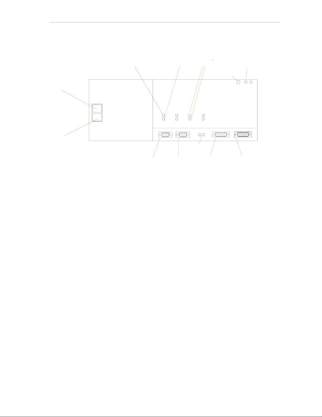
CompactGC manual
Carrier gas in
(1/16” Swagelok )
Mains switch
220V power
connec t io n
EZChrom
RS 232 connec t or
(D sub 9 pole)
Figure 2.1: electrical and pneumatic connections
Split out
(1/16” Swag elok)
CGC Editor
RS 232 connector
(D sub 9 pole)
Detector ga s in
1/16” Swag el o k)
Flash
programming
Actuator He-Air
(1/8” Swagelok)
Digital output
(D sub 15 po le)
Detector out
(1/16” Sw agelok)
Digital input
(D sub 15 pole)
6
Page 10
CompactGC manual
3. Instrument description
The CompactGC is a fully digital 19” rack GC, dedicated for fast gas analysis (however
analysis of liquid samples is also possible). The instrument uses reliable well-known
technique like Valco
columns with down sized dimensions, to obtain short analysis times. Typical analysis
times are 10 seconds to 2 minutes. The CompactGC editor, a dedicated program for
method programming, sets all parameters. The CompactGC is an up to 3-channel
instrument, with a choice of four different detectors. The signal of the detectors is
available in digital format, for use with the EZChrom
form for connection to other data systems. The basic setup of the system is shown in
figure 3.1.
®
valves, robust detectors and standard available capillary
®
data systems, as well in analog
detector
electronics
digital
gas
power
supply
control
detectors
Figure 3.1: Basic system
column
oven
valve
oven
7
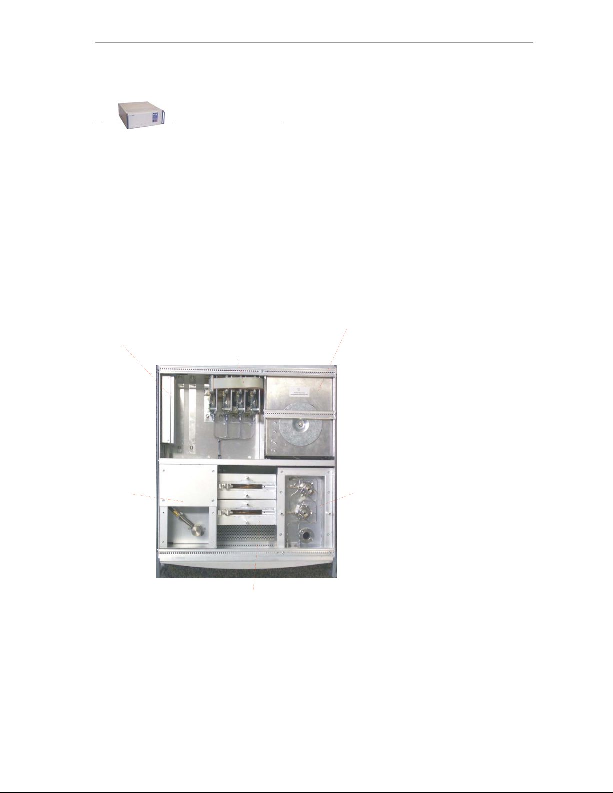
Page 11

CompactGC manual
The front half of the instrument contains the ‘chromatography hardware’: on the right
side the valve oven for (maximum 3) heated valves, in the middle the isothermal
column oven(s) (maximum 3), on the left side the detector compartment, for up to 3
detectors. A module for cryogenic trapping, in case of trace gas analysis, can be
installed in place of one of the column ovens.
On the back half of the instrument, from right to left side, the power supply, the digital
gas supply, and detector controllers can be seen.
3.1
Digital gas supply
The gas control of the instrument is fully digital, and can be present in two types of
modules:
• Carrier Gas Module (CGM) for carrier gas
• Detector Gas Module (DGM) for detector gasses
CGM
The Carrier Gas Module is a sophisticated carrier gas supply device, which can be
operated in the following modes:
• Constant pressure
• Programmed pressure
• Pressure pulse (pressure surge)
Four different gasses can be used: helium, hydrogen, nitrogen and argon. In case of
change of carrier gas type, recalibration of the splitflow is needed. Contact your
service organization for more information. Hydrogen is not recommended for safety
reasons.
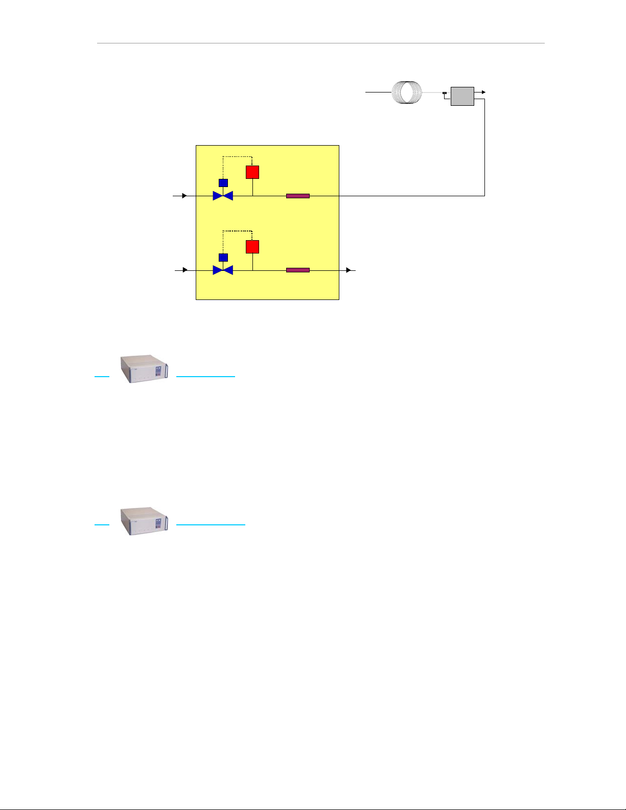
Constant pressure
The most common used operating mode is constant pressure, with digital control of the
split flow. See figure 3.2.
In this diagram, the constant pressure is obtained by the upper proportional valve and
pressure sensor (P). The lower proportional valve and pressure sensor, in combination
with a temperature compensated restrictor are controlling the split flow.
Normally, the optimum flow for a certain type of column is the starting point of method
development. The needed pressure can be determined by measuring the flow on the
detector outlet, of can be calculated using the available flow calculator (CGC editor).
8
Page 12
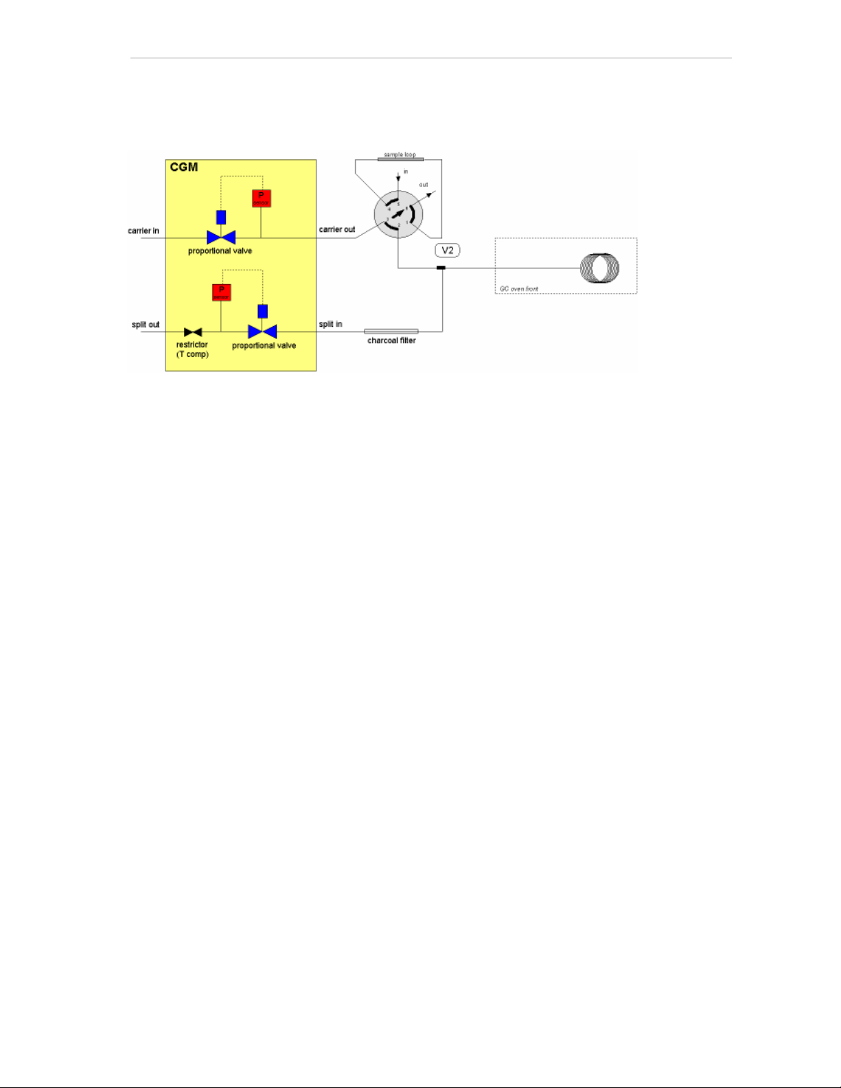
CompactGC manual
Figure 3.2: Diagram CGM
Programmed pressure, pressure surge
These modes of carrier gas control are obtained by programming the targeted
parameters using the Run Time Table. See chapter 5 for more details.
If the CompactGC runs out of carrier gas (no inlet supply), the system switches to the
Hibernate mode (all flow and temperature channels are set to value 0) and cools
down.
The GC needs a reboot (mains power switch, or ‘warm reset’ from the CGC editor
menu) to return to normal operation.
DGM
The second type of digital gas supply contains two pressure channels, and is therefore
used to control two detector gasses, f.i. hydrogen and air in case of FID, or two
reference gasses in case of double TCD. In combination with a calibrated, temperature
compensated restrictor in the module, constant detector gas flows are obtained. See
figure 3.3. The flows needed for proper detector operation are entered using the CGC
editor program.
9
Page 13
CompactGC manual
detector gas in
proportional
valve 1
P
Pressure
sensor
Fixed
restrictor
(temperature
compensated)
capillary column 1
PPM
TCD front
TCD
TCD 1 out
P
detector gas in
(second detector)
Figure 3.3: Diagram DGM
3.2 Valve oven
The valve oven is an independent heated temperature compartment that provides:
• housing for maxi mum 3 Valco
®
valves, for several configurations like injection,
backflush, streamselection, etc.
• heated sample inlet
• housing for sample conditioning (filtering, pressure reducing, etc.)
The oven can easily be accessed for maintenan ce, injection-loop changing, etc.
3.3 Column oven
In the CompactGC, up to three column ovens can be installed. In order not to lose
analysis time compared to a temperature programmed run (cooling down phase), the
analysis conditions are normally developed on base of isothermal analysis. Therefore
the applied ovens are isothermal and highly stable. The three ovens have independent
temperature control, so each column operates at its optimum temperature. The
standard supplied oven is used for fused silica columns with an internal diameter of 0.32
mm maximum. For wide-bore columns (0.53 mm id), metal columns are advised. The
most common used columns are 2-15 meter/0.32 mm id fused silica. In the oven,
columns with a winding diameter of 8 cm are installed. These columns can be ordered
in this dimension,
mentioned diameter. See chapter 6.1 for column installation.
Ovens for packed columns are available on request.
but also standard columns are used, after rewinding them to the
10
Page 14
CompactGC manual
3.4 Detectors
Four detectors are available: Thermal Conductivity Detector (TCD), Flame Ionisation
Detector (FID), Pulsed Discharge Detector (PDD) and Photo Ionisation Detector (PID)
(available end 2003). Up to three of these detectors can be configured in the
CompactGC.
TCD
The TCD is a very widely used detect or for analysis of gases, but in principle all
components with different thermal conductivity in relation to the carrier gas can be
detected. The response is concentration dependant: a higher column flow or make-up
flow results in a decreased sensitivity.
This detector is a dual channel microvolume cell with two filaments on constant mean
temperature. See figure 3.4.
dual filaments
analysis flow
Figure 3.4: TCD detector
reference fl o w
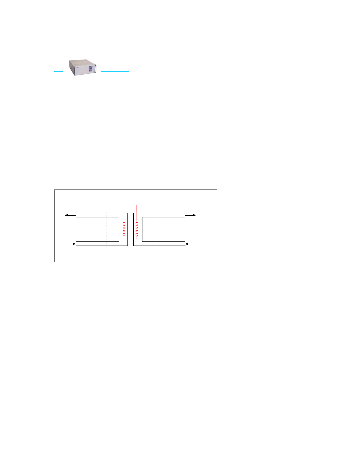
Operation principle
The filaments are continuously losing heat to the wall of the detectorcell by the thermal
conducting carrier gas (see figure 3.5). When a component with a different thermal
conductivity compared to the carrier gas pass es the filament, the electronic circuit in
which both filaments are integrated (Wheatstone bridge) is adjusting the current to
maintain the constant filament temperature. This current change is dependant on the
component concentration, and is convert e d to a chromatographic signal that can be
handled by the data system.
11
Page 15

CompactGC manual
capillary column 1
analysis
reference
Figure 3.5: Principle of the TCD
TCD front
TCD
TCD front out
The reference flow is supplied by a Detector Gas Module (DGM), and this flow is also
used for make-up gas according figure 3.5. This resu lts in a better peak shape,
especially for the higher concentrations, and a less critical column connection.
Consequently at the ‘TCD out’ exit both flows are measured together. If the column
flow needs to be checked, the reference flow can be switched off for a short time
(don’t forget to switch off the filament first). The normal reference flow is 1-2 ml/min.
Since the response of the detector is concentration dependant, a higher reference
flow results in lower sensitivity.
Operation conditions
Cell temperature: 10-20 ºC above column temperature
Filament (bridge) temperature: 20-120 ºC above cell temperature, depending on
required sensitivity
Reference flow: 1-2 ml/min
Polarity: depending on carrier gas
Range: depending on required sensitivity
FID
Operation principle
In gas analysis, the FID is popular for carbon-hydrogen containing compounds, due its
high sensitivity, good stability, and wide linear response. The response is massdependant, so flow rate does not affect the sensitivity.
In the FID (see figure 3.6), the effluent of the column is mixed with hydrogen, this mixture
is burned as it emerges from a metallic jet. This jet acts as one electrode (polarizing
electrode), while a metallic collar surrounding the flame forms the second electrode. A
potential is applied across the pair of electrodes to accelerate the electrons that are
generated during the combustion process of the organic compounds. The resultant
ionization current is sent to an electrometer impedance amplifier, and converted into a
suitable output signal.
12
Page 16

CompactGC manual
ignition coil
detector cell
collector electrode
polarized electrode
base body
electrometer
air
hydrogen
flame jet
column
Figure 3.6: Diagram of the FID
The hydrogen is mixed with the carrier gas at the column outlet, acting also as a makeup gas. For safety reasons, leakage should be avoided here.
The FID detector cell can easily be removed from the detector base body (it is advised
to lower the temperature first). With a special tool, the flame jet too can be removed.
Operation conditions
Temperature: 10-20 ºC above column temperature, minimum 120 ºC, to avoid
condensation of the formed water
Hydrogen flow: 30 ml/min
Air flow: 300 ml/min
During ignition, the hydrogen pressure is raised by 40 % for easy start of the flame. This is
performed automatically when the ignition button is actuated on the related TAB
page. The ignition current is switched off after 6 seconds. Note that the ignition state on
the TAB page will remain to ‘on’ (since the control program is an editor), so when the
flame has to be ignited again (f.i. after the column was changed), first ‘ignite off’ has to
be send to the CompactGC, followed by ‘ignite on’.
13
Page 17

CompactGC manual
PDD
Operation principle
The Pulsed Discharge Detector (see figure 3.7) is a non-radioactive ionization detector
with a universal concentration dependant response. A stable, low power, pulsed DC
discharge in helium acts the ionization source. Eluants from the column, flowing counter
to the flow of helium from the discharge region, are ionized by photons from the helium
discharge above. Resulting electrons are focused towards the collector electrode by a
bias electrode.
Figure 3.7: Diagram of the PDD
The principle mode of ionization is photoionisat ion by radiation arising from the transition
of diatomic helium to the dissociative ground state. This is the well known Hopfield
emission. The photon energy from the diatomic helium continuum is in the range of 13.5
to 17.7 eV.
The PDD is essentially non-destructive (0.01-0.1 % ionization) and highly sensitive. The
response to organic compounds is linear over five orders of magnitude with minimum
detectable quantities (MDQ) in the low picogram range. The response to fixed gasses is
positive (the standing current increases), with MDQ’s in the low ppb range. The
detector response is universal except for neon and helium.
Operation
Since the PDD is highly sensitive, also to air, extreme care should be taken to leakages,
quality of carrier gas, and all possible sources of detector pollution. Although a helium
purifier is used, gas quality should be 5.0 (or N50) or better.
14
Page 18

CompactGC manual
To avoid unnecessary gas couplings, the system is directly connected to the gas supply
(figure 3.8), which means that the reducer pressure of the gas supply controls the
discharge flow. This flow has to be adjusted to 25-30 ml/min (ca. 350 kPa). On the gas
exit (vent) of the detector, the discharge flow as well as the column flow is
simultaneously present, so for measurement of the discharge flow, the column flow
needs to be switched off. The column flow can be calculated by subtracting the
discharge flow from the total flow.
customer gas supply
T-piece
fixed restrictor
PDD
reducer
FPM
capillary column
He cylinder
vent
Figure 3.8: GC system with the PDD
After a leak check of this CompactGC channel, and adjustment of the wanted flows,
the discharge can be started by the ‘pulser’ button on the related TAB page in the
CompactGC editor. The start of the detector is confirmed by a soft high frequenc y
sound, and a baseline raise.
Operation conditions
Temperature: 10-20 ºC above column temperature
Discharge flow: 30 ml/min, to be adjusted by external He gas supply regulator (350
kPa)
Range: 64-256 nA
PID
This detector is not released yet.
15
Page 19

CompactGC manual
4. Pre-concentration Module (PM)
For trace analysis of gases, sample components can be pre-concentrated using a
Peltier cooled micro trap. Contact your local supplier for more information about this
option.
16
Page 20

CompactGC manual
5. The CompactGC editor program
Since the CompactGC it selves has only two push buttons on his front for starting and
stopping the analysis, the CompactGC editor program is used to program all the
different GC parameters like temperatures, flow/pressures, detector setting, etc. The
CompactGC control program is an ed itor, which means that the different parameters
are first only edited on the PC screen; after pushing the SEND button the methodchanges are uploaded to the CompactGC and activated. After programming the
CompactGC conditions, if wanted, the editor can be closed, and the PC can be
disconnected from the PC, since all values are stored in the permanent memory of the
CompactGC, and the programmed sequence is carried out independently of the
CompactGC editor. When the editor program does remain active during the GC run,
all actu al values and status inform ation are displayed to inform the op erator.
When the user starts the CompactGC editor, automatically all configuration and
method information is send from the CompactGC to the PC. The configuration data
(like number of channels, detectors, etc, a lot of different configurations is possible) is
stored in the CompactGC, so the user can see immediately the correct presentation of
the parameters of the connected CompactGC.
Figure 5.1: Main window of the CompactGC editor
17
Page 21

CompactGC manual
COMMAND BUTTONS
GET METHOD
With this button, the CompactGC editor gets the complete method and configuration
information from the CompactGC.
SEND METHOD
The operator pushes this buttons when new entered method-parameters have to be
sent to the CompactGC. Only the changed parameters are sent.
STATUS
Besides the actual values displayed at the channel pages, a status window can be
opened to display all parameters of the different channels together, also during a GC
run. Also status information like run and sequence number, valve positions, etc, is
available here.
Figure 5.2: Actual Status display.
18
Page 22

CompactGC manual
START – STOP run
These buttons have the same function as both push buttons on the CompactGC. (The
instrument can also be started and stopped using the electrical connections on the
rear, see appendix 2).
TAB PAGES
FRONT – MIDDLE – BACK Channel
The three possible analysis channels are named front, middle, and back channel. The
front channel is in the closest position to the operator and the front of the instrument.
Each channel has its own tab-page, which contains all the relevant parameters for one
analysis: settings for carrier gas, temperatures, and detector . The set value and actual
value are both present. When the operator changes a parameter, always the SEND
button has to be used to load the CompactGC with the new information.
AUX
On this page, setting for external devices, if present, are shown.
VALVES
This page is used for test and development purposes. The external events, in most cases
valves, can be controlled directly from here. A mouse-click on the wanted event,
followed by the SEND buttons activates the choice. In the same way, the additional 8
parallel output bits can also be directly controlled.
RUN TIME TABLE (RTT)
This page controls different actions on time base. The time base is set to zero after each
start of the GC run. One of the actions is f.i. the valve command: after each GC start
the injection valve is actuated. The following columns are available:
Entry
The entry number of the table.
Time
The time at which an action takes place, after the run is started.
Lock
In order to edit the table in a user-friendly way, related commands can be linked
in time. F.i. in case of a fixed time between two different lines in the RTT, for one of
these lines a capital ‘A’ is entered in this particular column. For the other line a
small ‘a’ is set. When the time for ‘A’ is changed now, the same absolute shift is
performed on ‘a’.
19
Page 23

CompactGC manual
Sequence
This command is used in combination with the ‘reset sequence counter’
command in the next column of the table, which allows a certain action only to
be executed at a selected run number in a sequence. By resetting the sequence
counter, a loop is created, that is repeated every time. F.i. in a sequence of 10
analyses, only at run number 1 (needs to be entered in this particular column), a
selection valve is actuated for calibration purposes. Another applicat ion is stream
selection.
Command
The following actions can be selected in this column:
T set
The temperature of the available devices can be altered with
this command on time base
FP set
This command allows you to change flow and pressure settings
during the run
Valve
This command is used to activate the external events, mostly
valves. Since up to 8 events can be connected, also the valve
number has to be entered.
Output bit
The output bit command programs the state of the additional
8-bit parallel output. In case of another data than EZChrom
®
,
this command is used to start the data-acquisition. See
appendix 2.
Start chromatogram
In case of digital data connection to EZChrom
starts the data-acquisition. The use is mandatory in this case.
Autozero detector
During the run, the detector output signal is set to zero using this
command. Note that this act io n takes time, and no peaks are
allowed to elute during the autozero process.
Detector gain/range
During the run, the detector input sensitivity can be changed in
order to detect both high and low concentration peaks in the
same sample. This action takes time, so no peaks are allowed
to elute during the switching process.
®
, this command
20
Page 24

CompactGC manual
Load default method
During a run, the different parameters can be reset to their start
(method) values. This is convenient when a lot of parameters
have changed, and the original settings are needed during the
run.
Reset sequence counter
See the explanation of the sequence column.
End of this run
This command stops the present run of the CompactGC. In
case of digital data-collection by EZChrom
®
, the dataacquisition is stopped also. If the number of runs is 2 or more,
immediately the next run is started. Since the CompactGC
starts his next run immediately, and EZChrom
process the acquired data, the EZChrom
®
needs time to
®
runtime should
always be shorter than the CompactGC runtime. The time
EZChrom
®
needs between runs is dependent on the length of
the run, PC processor speed, network connections, etc.
Normally 5-10 seconds are appr opriat e.
Channel
If an action can be applied to more than device (temperature, flow, valves), a
channel number has to be entered.
Channel name
If name of the selected device is shown in this column.
Value
In case of a valve switching command, ‘1’ needs to be entered in this field to
activate the valve, and with value ‘0’ the valve returns to his standby position. In
combination with commands ‘T set’ and ‘FP set’ the new settings are entered
here. Commands like ‘autozero’ and ‘start chromatogram’ do not have a value.
Comment
In order to increase the readability of the RTT, comments can be entered for each
command line
For a better overview of the RTT, the operator can disable the automatic sort (on
retention time) of the table.
On the end of this page, the number of runs is entered. This number will be
executed after the start-button is pressed. A number of 999 is equal to infinite
analysis.
21
Page 25

CompactGC manual
The Run Time Table will automatically sort on retention time. A line can be modified
after it has been scrolled to the editing window. Lines can also be added or deleted.
Like other parameters, the edited RTT will become active after it has been send to the
CompactGC by using the SEND button in the main window .
PULL DOWN MENU’s
File
Besides the functions of the above mentioned command buttons, the CompactGC
method can be printed from here.
View
Status
This line has the same function as the Show Status command button.
Log file
From this line, two types op log files, CompactGC -memo, and CompactGC actual date can be l oaded to view every normal action and fault messages.
Drawing
This is a viewer for BMP and JPG files, and is used to view the schematic diagram
that is supplied with the instrument for convenient editing of the CompactGC (see
figure 5.3).
Figure 5.3: View drawing
22
Page 26

CompactGC manual
Method
T, F and P defaults
Valve and bits default
Run time table
These windows offer the same functionality as the TAB pages.
Detector defaults
Figure 5.4: Detector defaults
In addition to the detector settings on the TAB pages, parameters less frequently
used are available on this page:
T filament (TCD)
This parameter sets the filament temperature of the TCD. A high
value in relation to the TCD block temperature means high
sensitivity.
Input gain (TCD)
Gain factor of the input amplifier. A higher value corresponds to
higher sensitivity (but noise is more amplified too).
Input polarity (TCD)
Polarity of the TCD signal, depends on the type of carrier gas.
Input current (FID, PDD and PID)
Input range of the detector amplifier. A lower value means
higher sensitivity.
23
Page 27

CompactGC manual
Sample rate
The number of samples per second (sps) is entered here. The
correct value depends on the peak width. F.i. for 0.32 mm id
columns, peak widths of 0.5 to 2 seconds are normal. For a
correct analog to digital conversion without losing data
integrity, 15 to 25 points per peak are necessary. This means a
sps value of 25 or 50. In case of analog output, only on this
page the sps parameter can be selected. In combination with
EZChrom
®
, this setting is overruled by the entered value in the
data system, but the choice is limited to the listed values (12.5,
25, 50 and 100 Hz).
High voltage (FID, PDD and PID)
In case of ionization detectors, this parameter switches the
polarization voltage on and off.
FID ignite (FID)
After setting the correct detector gas values for hydrogen and
air, this button activates the ignition coil in the detector housing
for 6 seconds so the flame will turn on. During this time, the
hydrogen pressure is raised for better ignition.
Pulser (PDD)
When using the Pulsed Discharge Detector, this buttons start the
discharge current.
Lamp (PID)
By this button, the lamp in case of PID is turned on.
Detector analog output
When the analog output is used, the output gain and shift
(offset) are enter ed here.
Test chromatogram
After activating this option, during the next run only a
synthesized chromatogram is added to the present detector
signal. This feature is used for test purposes.
Setup
Comport
For RS 232 communication com1 to com12 can be used.
24
Page 28

CompactGC manual
FP calculator
On this page, the column flow can be calculated.
The column flow is related to the carrier gas inlet pressure and gas type, the
column dimensions and the column temperature. Note that P
(column outlet
out
pressure) also influences this flow; in case of FID and PDD, this pressure is
atmospheric, but in case of TCD, this pressure is higher since a restriction tubing is
presence between the column end and the TCD. The pressure can be det ermined
by measuring the column flow on the detector outlet, and entering the right P
out
value in the calculator.
The calculator uses temperature driven viscosity polynominals.
Tmax
This page allows you to protect columns from temperatures above the maximum
allowable temperature. The User Tmax can be set, the System Tmax is a fixed
value. This parameter is protected by a password. After changing parameters, use
the command ‘Send changes to GC’ to save the changes in the CompactGC.
Edit positions.
This option is password protected, and gives the opportunity to
change the position of the different devices (temperature and
flow/pressure) and detector settings on the TAB pages. Position 100,
200, 300 and 400 are referring to the Front, Middle, Back and Aux
channel page. On each page, the following 20 positions are
available:
X00 X01
X02 X03
X04 X05
X06 X07
X08 X09
X10 X11
X12 X13
X14 X15
X16 X17
X18 X19
(X = TAB page number)
After changing parameters, use the command ‘Send changes to GC’ to save the
changes in the CompactGC.
Edit T/F device names.
This option is password protected, and gives the opportunity to change the names
of the temperature controls (f.i. for column name display) and flow devices (f.i.
when another carrier gas is used). After changing parameters, use the command
‘Send changes to GC’ to save the changes in the CompactGC.
25
Page 29

CompactGC manual
Edit Flame-Off level.
Figure 5.5: Flame-Off window
For safety reason, the FID signal level is monitored after each run; this level is
displayed in the STATUS page (only in stand-by mode). In case of a Flame-Off
situation, this option avoids spreading of hydrogen in the CompactGC. In the
example the ‘action level’ is set to 1 pA; if the signal level drops below this value,
the system will:
- go in ‘Hibernate mode’. This means that all gas supply channels will close, and
the system will cool down, or
- close the hydrogen channel for that detector only, or
- take no action (so there is NO protection!)
The flame on/off status, according to the ‘FID action level’ is also displayed in the
STATUS window.
IMPORTANT: for safety reasons, these parameters need to be set correctly.
Especially in case of low-bleed columns, there is a small (1-2 pA) signal drop when
the flame goes out, so the ‘FID action level’ needs to be set precisely. It is the
responsibility of the end user to obtain an adequate protection level in using these
parameters.
When a Flame-Off situation occurs, a warning message (pop-up window in the
CGC editor) is displayed, and the operator has 2 minutes time to change the
situation before the selected action is executed. When the FID flame is restored,
the pop-up window automatically disappears.
The flame-off detection is not active during data acquisition, so make sure there is
some spare time between each run (data collection) to detect a possible FlameOff condition. This time is reserved by setting the ‘start chromatogram’ in the Run
Time Table to 1 second or later.
26
Page 30

CompactGC manual
Control
Start / Stop analysis:
Function similar to the buttons displayed on the main menu.
FID Flame-Off disable until (re)arming
This command disables the Flame- Off detection when this is temporar y not
wanted. The detection is armed again by (1) the following command, (2) a new
flame ignition, (3) a CGC restart. The status of the Flame-Off detection
(enabled/disabled) is list ed in the STATUS window.
FID Flame-Off arm
This command enables the Flame-Off detection manually. The status of the FlameOff detection (enabled/disabled) is listed in the STATUS window.
Restart CGC – warm (re)boot
This command allows a remote (soft) restart of the CGC. This menu addition is
primary targeted to rest art the system after a Flame-Off alarm that brings the GC
in protected mode and/or canceling a Hibernate mode.
Note: This warm reset is nearly the same as a mains power on/off, with the
exception that a major protective alarm (f.i. in case of a temperature sensor
failure) cannot (and should not) be resetted.
About
Displays the software version of this editor program
27
Page 31

CompactGC manual
6. Operation
6.1 Column installation
Columns with different external diameter can be installed. See the accessories
catalogue for the available dimensions. Normally 0.32 mm id (0.45 mm od, 0.5 mm
ferrule needed) columns are used, but also 0.25 mm id and 0.53 mm id (metal) can be
applied.
Figure 6.1: Injector (valve) side
Injector (valve) side
• Install the knurled nut and the ferrule (with appropriate internal diameter) without
the column).
• Cut the column end to the correct length, in such a way that no stress is present
on the column after installation.
• Install the column, using the heated aluminum interface path between the
column oven and the valve oven. If the column does not enter the knurled nut on
the valve easily, guide it with tweezers or another tool.
• Tighten the nut by hand.
28
Page 32

CompactGC manual
Detector side (TCD and FID)
• Install the knurled nut and the ferrule (with appropriate internal diameter) without
the column).
• Cut the column end to the correct length, in such a way that no stress is present
on the column after installation.
• Guide the column into the nut.
• Tighten the nut by hand
nut
nut
valve
Figure 6.2: Column installation
Detector side (PDD)
The distance between the column end, and the lower part of the nut is 11.4 cm.
Figure 6.3: Installation of the column with the PPD detector
29
Page 33

CompactGC manual
6.2 Leak check
A leak check is performed by pressurizing the sealed system with carrier gas. Any leaks
are registered by a drop in the pressure reading. The pneumatic diagram, supplied with
the system, is a useful tool.
TCD channel
• turn of the bridge temperature
• turn off the reference gas (send value 0)
• seal the end of the channel by a 1/16” cap on the detector outlet
• set the total flow to zero
• set the inlet pressure to 100 kPa, and after the channel is pressured, set the
pressure to zero
• observe the pressure
FID channel
Extreme care should be taken to a leak-tight gas connection since hydrogen is used as
FID feeding gas. This feeding gas is mixed with the carrier gas at the end of the column
(see figure 6.2; left nut). In case of a leak, hydrogen will enter the column oven.
For a total check of this channel, the FID detector is disconnected, and the flame jet is
replaced by a blind jet.
• turn off the hydrogen and air gas supply (send value 0)
• seal the detector base or the end of the column
• set the total flow to zero
• set the inlet pressure to 100 kPa, and after the channel is pressured, set the
pressure to zero
• observe the pressure
An electronic leakchecker may also be used.
PDD channel
For this channel, except the gas from the digital gas controllers, also discharge gas is
supplied directly via a restrictor (see the PDD, chapter 3.4).
• turn off the pulser
• set the total carrier flow to zero
• set the inlet pressure to 150 kPa, and after the channel is pressurized, set the
pressure to zero
• close the external gas supply to the CompactGC
• wait until a stable pressure readout is obtained (approximately 150 kPa) , and
observe if this value remains stable
30
Page 34

CompactGC manual
6.3 Quick start up
In case of digital data communication (EZChrom®), power-on the CompactGC first,
followed by the data system to establish the digital connection.
The following steps are important in starting up the analysis:
Remember that the CompactGC control program is an editor, and ‘SEND’ is
necessary to activate the entered values
• install the column, and perform a leak check
• set the correct column flow by adjusting the carrier gas pressure (TAB page). This
flow can be measured on the detector outlet, or can be calculated using the FP
calculator (remember that P
depends on the used detector)
out
• set the desired column temperatures depending on the application; in constant
pressure mode, the column flow is dependant on the column temperature, so
adjustment of the pressure can be necessary
• send the detector parameters (see chapter 5)
• enter the correct values for valve switching and d ata c o llection in the run time
table
For data-acquisition with EZChrom
®
the command ‘start chromatogram’ should be
present (at 1 sec). For analog data collection set output bit 7 to 1 at 1 second, and
enter value 0 at 2 seconds.
The end of the run has to be programmed in the RRT (figure 6.4) as well in the data
system. Since the CompactGC starts his run directly after the preceding one, and the
data system needs time to process and save the acquired data, the runtime of the data
system always needs to be shorter than the runtime of the CompactGC (5-10 seconds ,
depending on the speed of the data system and, if present, the network connection).
Enter short valve switching periods for injection (f.i valve on (1) at 1 second; valve off (0)
at 2 seconds).
Enter also the number of analysis on this page.
• in case of analog data-acquisition, enter the correct acquisition rate on the
‘detector defaults’ page (with digital data, the EZChrom
®
setting will be copied)
• Set up the data system method: enter the correct data-acquisition rate for each
channel, and a runtime that is 5-10 seconds shorter than the CompactGC runtime;
in case of EZChrom
start the data system (‘waiting for trigger’ is displayed)
®
, only 12.5, 25, 50 and 100 points per seconds are allowed;
• switch on the detector(s); in case of TCD: activate the Autozero function; the
‘SEND’ command is not needed for this function
• If the CompactGC reports ‘ready’, the run can be started
31
Page 35

CompactGC manual
Figure 6.4: run time table window
In case the CompactGC was switched off, the data system has to be closed and
restarted for re-establishing the digital communication with EZChrom
®
.
32
Page 36

CompactGC manual
7. Maintenance and troubleshooting
Full instrument servicing will normally be performed by an Interscience service engineer
under the instrument warranty, or, when this has expired, possibly under a Service
Contract Program.
Filters
The filters in the split line of the carrier gas normally need no replacement, since their
function is to protect the electronic split regulation by a gradually release of the vented
components.
Ferrules
Ferrules and seals should be replaced when they are too flat or broken to produce a
good seal.
Valves
Depending on the type and use of Valco
on a regular base.
Log file
In case of electronic failure, inspect the log file (CompactGC editor: view log file).
®
valve, the rotor seals need to be replaced
33
Page 37

CompactGC manual
Apendix 1: EZChrom® / EZStart® settings
The datacommunication between EZChrom
®
and the CompactGC is based on the
SS420x protocol. The following parameters need to be entered:
Interface configuration
Tools/interface configuration
When the correct RS-232 connection is present, the information shown at ‘serial
number’ confirms the communication with the CompactGC. When not connected, or
not active, the window below is shown. The connection should be validated before
starting another activity.
34
Page 38

CompactGC manual
Instrument configuration
The interface connection window can be closed, and the configuration window of the
instrument needs to be opened:
Add modules according the CompactGC configuration. Besides one to three
detectors, the event configuration should also be selected.
35
Page 39

CompactGC manual
Detector configuration
Detector 1 corresponds to the front channel of the CompactGC, detector 2 to the
middle channel, and detector 3 to the CompactGC back channel. Appropriate names
can be entered here (FID front, TCD back, etc.).
For TCD, the Y-as Multiplier is set to 0.002500, for FID/PDD/PID 0.00100 has to be entered.
Serial port: corresponding to the used RS-232 port.
Channel: 1 for front channel; 2 for middle channel; 3 for back channel
36
Page 40
CompactGC manual
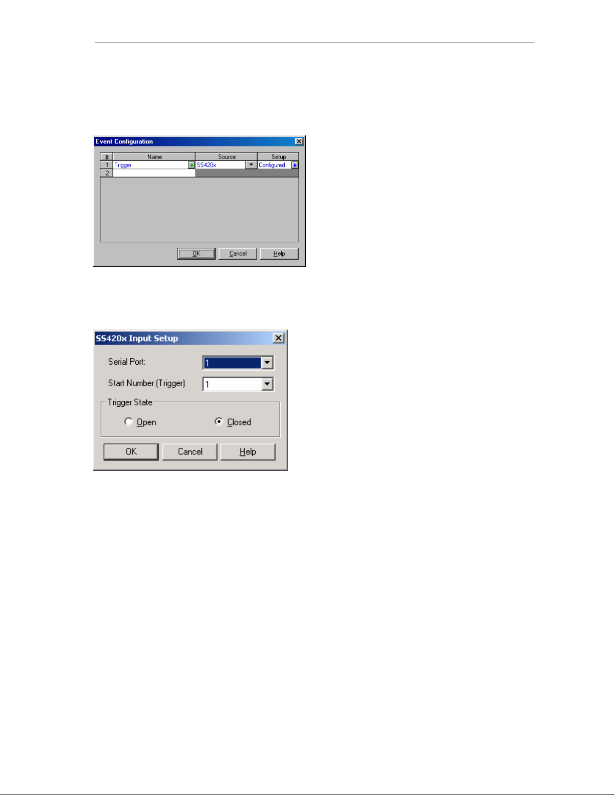
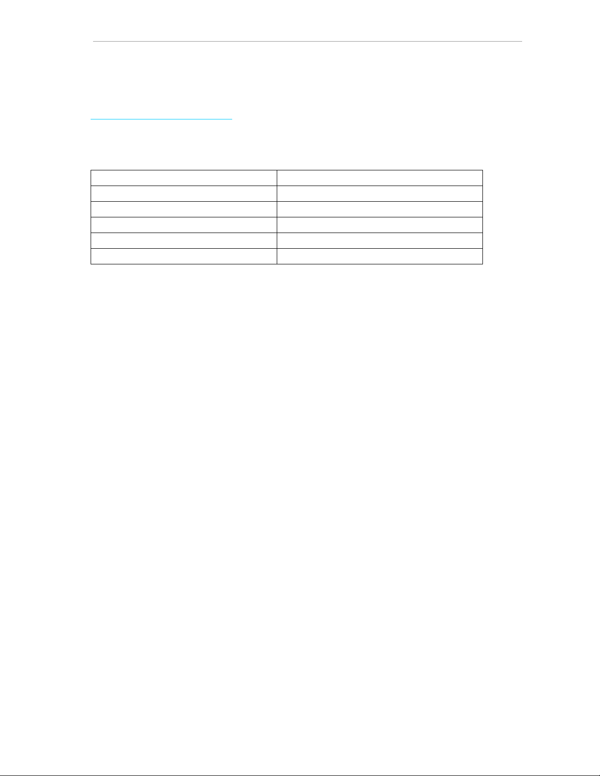
Event configuration
When the blue arrow is selected, ‘triggered state closed’ needs to be entered.
The Trigger should also be set to the used RS-232 port in other to start the EZChrom
data-acquisition by the CompactGC.
Instrument setup
After finishing the configuration, the instrument can be opened.
In EZChrom
®
, open Method/Instrument Setup and configure each channel:
®
37
Page 41

CompactGC manual
Complete the setup by setting the external trigger as shown below.
38
Page 42

CompactGC manual
Apendix 2: Electrical connections
For both RS 232 connections, a 9-pole D-sub standard RS-232 cable is needed.
Digital input
1
915
8
Pin description Input level
1 D-in bit 0 – start CompactGC L=Tue (TTL/OC/relais)
2 D-in bit 1 – stop CompactGC L=Tue (TTL/OC/relais)
3 D-in bit 2 L=Tue (TTL/OC/relais)
4 D-in bit 3 L=Tue (TTL/OC/relais)
5 D-in bit 4 L=Tue (TTL/OC/relais)
6 D-in bit 5 L=Tue (TTL/OC/relais)
7 D-in bit 6 L=Tue (TTL/OC/relais)
8 D-in bit 7 L=Tue (TTL/OC/relais)
9 ground 0 V
10 ground 0 V
11 ground 0 V
12 ground 0 V
13 ground 0 V
14 ground 0 V
15 ground 0 V
Digital output
(internal pull-up; bit 0-5=10K; bit 6-7=1K )
8
15
1
9
39
Page 43

CompactGC manual
Pin Description Output level
1 D-out bit 7 – start out Low active ; open
2 D-out bit 6 – ready Low active ; open
3 D-out bit 5 Low active ; open
4 D-out bit 4 Low active ; open
5 D-out bit 3 Low active ; open
6 D-out bit 2 Low active ; open
7 D-out bit 1 Low active ; open
8 D-out bit 0 Low active ; open
9 Ground 0 V
10 Ground 0 V
11 Ground 0 V
12 Ground 0 V
13 Ground 0 V
14 Ground 0 V
15 Ground 0 V
Analog detector output (optional)
If present, the analog detector is a 9-pole D-sub connector (female on rear
CompactGC). This output provides a high stable, high resolution (20 bits) analog signal.
In order to preserve the quality as good as possible, short cables are advised. Beside
the output signal, two additional connections are important: shield and ground. The
shield is not connected at the CompactGC side, and is necessary to protect the signal
from external influences. This cable needs to be connected at the data system. The
ground connection is necessary to equal the ground level of the CompactGC to the
data system, and is important for safety reasons, and omitting damage to the system.
pin Description
1 0 V - front channel
6 1 V - front channel
2 0 V - middle channel
7 1 V - middle channel
3 0 V - back channel
8 1 V - back channel
Shield (not connected on CompactGC side;
connect on data system side)
5 ground
40
Page 44
CompactGC manual
Apendix 3: LED status display
Green and Red system LED‘s (CompactGC front)
display functionality
GREEN slow blinking (short Off) READY (all active devices)
Green Blinking (1 Hz) NOT READY
RED off NO RUN
RED continuous on RUN (run time table)
RED fast blinking (2.5 Hz) ALARM (check log file.)
41
Page 45

CompactGC manual
x
IInnddeex
About (Pull down menu’s) 27
Analog detector output
Electrical connections 40
Analog output (Pull down menu’s) 24
Atmosphere 2
Autozero (Run time table) 20
Aux (Tab pages) 19
Back channel (Tab pages) 19
Bits default (Pull down menu’s) 23
Channel (Run time table) 21
Channel name (Run time table) 21
Classification, instrument 4
Column installation 28
Column oven 10
Command (Run time table) 20
Command buttons 18
Get method 18
Send method 18
Start - stop run 19
Status 18
Comment (Run time table) 21
Comport (Pull down menu’s) 24, 27
Control (Pull down menu’s) 27
Demand 5
Detector analog output (Pull down
menu’s) 24
Detector configuration 36
Detector defaults (Pull down menu’s) 23
Detectors 11
Digital connections 5
Digital input 5
Electrical connections 39
Digital output 5
Electrical connections 39
Drawing (Pull down menu’s) 22
Edit positions (Pull d own menu’s) 25, 26
Editor program 17
Electrical connections 39
End of this run (Run time table) 21
Entry (Run time table) 19
Event configuration 37
EZChrom® / EZStart® connections 5
EZChrom® / EZStart® settings 34
Ferrules 33
FID 12
High voltage (Pull down menu’s) 24
Ignite (Pull down menu’s) 24
Input current (Pull down menu’s) 23
Leak check 30
File (Pull down menu’s) 22
Filters 33
FP set (Run time table) 20
FPM
Digital gas supply 8
Front channel (Tab pages) 19
Gas supply 8
Gasses 4
Connections 4
Demand 5
Pressure 4
Quality 4
Get Method (Command button) 18
Ground 2
High voltage (Pull down menu’s) 24
Hydrogen, use of 3
Ignite (Pull down menu’s) 24
Input current (Pull down menu’s) 23
Input gain (Pull down menu’s) 23
Input polarity (Pull down menu’s) 23
Installation 4
Instrument configuration 35
Instrument description 7
Instrument setup 37
Interface configuration 34
Lamp (Pull down menu’s) 24
Leak check 30
LED status display 41
Load default method (Run time table) 21
Lock (Run time table) 19
Page 46

CompactGC manual
Log file 33
Log file (Pull down menu’s) 22
Maintenance 33
Method (Pull down menu’s) 23
Middle channel (Tab pages) 19
Operation 28
Output bit (Run time table) 20
Oven
Column 10
Valve 10
PDD 14
High voltage (Pull down menu’s) 24
Input current (Pull down menu’s) 23
Leak check 30
Pulser (Pull down menu’s) 24
PID 15
High voltage (Pull down menu’s) 24
Input current (Pull down menu’s) 23
Lamp (Pull down menu’s) 24
Power requirements 5
Pre-concentration Module 16
Pull down menu’s 22
Pulser (Pull down menu’s) 24
Quick start up 31
Reset sequence counter (Run time
table) 21
RTT (Tab pages) 19
Run time table (Pull down menu’s) 23
Run time table (Tab pages) 19
Safety 2
Sample rate (Pull down menu’s) 24
Send method (Command button) 18
Sequence (Run time table) 20
Setup (Pull down menu’s) 24
Software 17
Space requirements 4
Start chromatogram (Run time table) 20
Start run (Command buttons) 19
STATUS (Command button) 18
Status (Pull down menu’s) 22
Stop run (Command button) 19
T filament (Pull down menu’s) 23
T set (Run time table) 20
T, F and P defaults (Pull down menu’s) 23
Tab pages 19
Aux 19
Front - middle - back channel 19
Run time table 19
Valves 19
TCD 11
Input gain (Pull down menu’s) 23
Input polarity (Pull down menu’s) 23
Leak check 30
T filament (Pull down menu’s) 23
Test chromatogram (Pull down menu’s)
24
Time (Run time table) 19
Tmax (Pull down menu’s) 25
Tools/interface configuration 34
Troubleshooting 33
Value (Run time table) 21
Valve (Run time table) 20
Valve default (Pull down menu’s) 23
Valve oven 10
Valves
Maintenance and troubleshooting 33
Valves (Tab pages) 19
Ventilation 4
View (Pull down menu’s) 22
 Loading...