

InterQuip EASIKIT EK600-41 User Manual

.
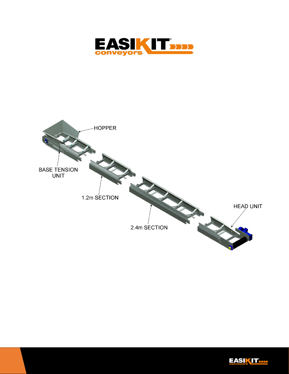
EK600
.
INSTRUCTION
MANUAL
EK600 INSTRUCTION MANUAL
EK600
The manufacturer does not accept responsibility for any loss, damage to other equipment, injury to personnel or any other circumstance resulting from the use of
our equipment. All rights reserved. No part of this publication may be reproduced, stored in a retrieval system, or transmitted in any form or by any means electronic, mechanical, photocopying, recording or otherwise - unless the permission of the publisher has been given beforehand. © All specifications are subject
to change without notice
2

EK600 INSTRUCTION MANUAL
CONTENTS
INTRODUCTION ...................................................................................... 4
1 SAFETY INSTRUCTIONS ................................................................... 5
2 ENVIRONMENTAL PROTECTION .......................................................... 5
3 CONFORMITY .......................................................................................... 5
4 TOOLS / PPE / PARTS & PACKAGING LIST ........................................... 6
4.1 Tools and Equipment Required .................................................... 6
4.2 Recommended PPE ..................................................................... 6
4.3 Packing List .................................................................................. 6
5 LIFTING AND SUPPORTING ............................................................... 7 - 8
5.1 Manual Handling .......................................................................... 7
5.2 Mechanical Handling .................................................................... 7
5.3 Supporting in temporary Installations ........................................ 8
5.4 Helpful Hints ................................................................................. 8
6 ASSEMBLY ....................................................................................... 8 – 37
6.1 Assembly Procedure ............................................................ 8 – 9
6.2 Assembly Instructions ........................................................ 9 – 11
6.3 Return Rollers .......................................................................... 11
6.4 Fitting Belt - Clip Joint ...................................................... 12 – 13
6.5 Fitting Belt – Vulcanized Joint .......................................... 13 – 14
6.6 Fitting Motor & Gearbox ........................................................... 15
6.7 Fitting EASIKIT® Support Stands ..................................... 16 – 23
6.8 Electrical Installation ................................................................ 24
6.9 Emergency Stop Grab Wires.................................................... 25
6.10 Motion Sensors ........................................................................ 25
6.11 Belt Tensioning and Tracking ........................................... 26 – 28
6.12 Hoppers ................................................................................... 29
6.13 Bottom Covers ......................................................................... 29
6.14 Side Guides ..................................................................... 30 – 31
6.15 Belt Scrapers ................................................................... 32 – 35
6.16 Auto Grease Units .................................................................... 36
7 EASIKIT® MOBILE .......................................................................... 37 – 38
8 EASIKIT® RADIAL ........................................................................... 39 – 40
9 EASIKIT® ROUTINE MAINTENANCE ............................................. 41 – 47
10 EASIKIT® EK600 PARTS LIST ................................................................ 48
11 EASIKIT® EK600 EXPLODED DIAGRAMS ..................................... 49 – 54
12 WARRANTY ............................................................................................ 55
3

EK600 INSTRUCTION MANUAL
INTRODUCTION
This product is designed to provide years of reliable service throughout its working life.
The unique design of the EASIKIT
and hands-on experience in the conveyor industry. In depth experience, attention to detail, a
commitment to quality and excellent service are the foundations that have built a first-rate
reputation and provided complete customer satisfaction.
Please take time to read this Instruction Manual; it will guide you step by step through
installation to ensure you get the maximum performance from your conveyor.
This manual covers installation, parts required, maintenance, CE conformity and warranty
®
Conveyor System is the result of 30 years of research
conditions.
We, the designers and distributors want you to achieve a high level of satisfaction with your
EASIKIT
to contact us.
®
Conveyor System. If you have any comments or questions, please do not hesitate
InterQuip USA LLC
4 Duke Place
Norwalk, CT 06854
(203) 322-2600
info@interquip.net
4

EK600 INSTRUCTION MANUAL
1. SAFETY INSTRUCTIONS
To use this equipment properly, you must observe the safety regulations, the assembly instructions and the
operating instructions to be found in this manual. All persons who use and service the equipment have to be
acquainted with this manual and must be informed about any potential hazards. Children and frail people
must not use the equipment. Children should be supervised at all times if they are in the area in which the
equipment is being used.
It is also imperative that you observe the accident prevention regulations in force in your area. The same
applies for general rules of occupational health and safety.
The manufacturer shall not be liable for any changes made to the equipment or for any damage resulting
from such changes.
Caution:
a) Read all instructions. Failure to follow instructions listed below may result in electric shock, fire
and/or serious injury. Always isolate from electrical supply before carrying out maintenance,
including changing the belt.
b) Do not attempt to assemble the conveyor in high winds
c) Prior to assembling your conveyor check components against parts list to ensure that there are no
shortages, the assembly should not commence unless all items are present.
2. ENVIRONMENTAL PROTECTION
Recycle unwanted materials instead of disposing them as waste. All parts and packaging should be sorted,
taken to the local recycling center and disposed of in an environmentally safe way.
3. CONFORMITY
EASIKIT® conforms to relevant safety standards in the country in the EU where the product is manufactured.
The machinery, taking into account the state of art, complies with, or is designed and constructed so far as it
is possible to comply with, the relevant health and safety regulations.
5

EK600 INSTRUCTION MANUAL
4. TOOLS / PPE / PARTS & PACKING LIST
4.1 TOOLS AND EQUIPMENT REQUIRED
• Phillips screwdriver
• Adjustable spanner
• Podium steps
• Tape measure
• Large set square
• Offset wrench or socket wrench
• 17mm, 19mm & 24mm sockets
• SDS Electric hammer drill
• Large ratchet strap
• Temporary support frames/trestles
4.2 RECOMMENDED PPE
• Hard Hat
• Gloves
• Goggles
• Safety footwear
4.3 PARTS & PACKING LIST
• Supplied separately
6
EK600 INSTRUCTION MANUAL
5. LIFTING & SUPPORT
EASIKIT® EK600 Sections
Length
Width
Height
Weight
Head Unit without Motor
59.25”
36.5”
11.25”
188 lbs.
Head Unit with 3kw Motor
60”
40”
12”
265 lbs.
Tail / Base Tension Unit
60.75”
28.75”
11.25”
205 lbs.
4’ (1.2m) Section
53”
24.5”
11.25”
95 lbs.
8’ (2.4m) Section
100.5”
24.5”
11.25”
187 lbs.
Small Steel Hopper
31”
33.5”
12”
35 lbs.
Medium Steel Hopper
37”
37”
20”
66 lbs.
WARNING!
5.1 MANUAL HANDLING
• Individual sections should be handled by at least 2 people
• Sections & components over 50kgs will require mechanical handling
OBSERVE CORRECT LIFTING PROCEDURES AT ALL TIMES.
MIND YOUR BACK - THESE SECTIONS ARE HEAVY!
FAMILIARIZE YOURSELF WITH THE WEIGHT OF EACH SECTION
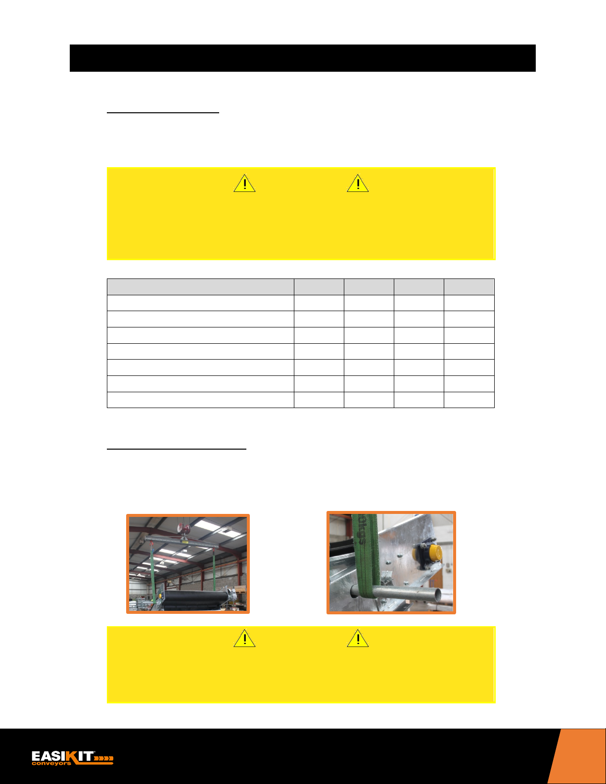
5.2 MECHANICAL HANDLING
• Conveyors up to 16’ (5.0m) long should be lifted into place with nylon straps to poles inserted
through the holes on the head and base tension units. Conveyors over 16’ (5.0m) long should
be lifted with at least six (6) nylon straps.
WARNING!
ENSURE THAT YOUR CONVEYOR IS CORRECTLY AND SAFELY
LIFTED AT ALL TIMES. ENSURE THAT NOBODY IS UNDERNEATH
THE CONVEYOR WHEN IT IS BEING LIFTED.
7

EK600 INSTRUCTION MANUAL
5.3 SUPPORTING IN TEMPORARY INSTALLATIONS
• Recommended support method for a temporary installation is scaffolding/temporary support
trestles which should be erected by a qualified person whilst the conveyor is being assembled.
ENSURE THAT THE CONVEYOR IS SUPPORTED SATISFACTORILY AT
REGULAR INTERVALS DURING ASSEMBLY – MAX 10’ (3M) OR 20’ (6M) WITH
STRINGERS – AS IT WILL BE TOO HEAVY TO MANUALLY LIFT ONTO
SUPPORTS WHEN COMPLETE
5.4 HELPFUL HINTS
The more supports there are used during assembly of your conveyor the easier it will be to
•
assemble.
Once your conveyor is fully assembled and operational you will find it beneficial to ensure that
•
there is a minimum gap of 100mm between any part of the conveyor and the floor as this will
help prevent material jamming on the returning belt.
6.1 ASSEMBLY PROCEDURE
Your conveyor has been delivered to you on
pallets (unless supplied ready assembled).
After opening the pallet, you will have all the
parts required to complete your conveyor
assembly.
Before you start...........read through instructions carefully and check that all the items listed on your
Parts & Packing list have been supplied. If any items are missing, contact your supplier immediately
prior to assembly.
You will need assistance.........you will find that assistance of at least two other people, and
appropriate mechanical handling equipment, will speed the job and make assembly easier and safer.
WARNING!
6. ASSEMBLY
8
EK600 INSTRUCTION MANUAL
Selecting your site……...choose an area that is firm, level, and capable of supporting the weight of
the conveyor and product to be conveyed on the belt. In addition, the base should be suitable to
facilitate secure anchoring of the conveyor feet.
You will require unrestricted access to all edges of the conveyor.
CONVEYOR STANDS MUST BE ANCHORED SECURELY AT THE FEET TO A
STABLE BASE. BUILDING ANCHORS ARE NOT SUPPLIED AS PART OF THE KIT
AND SHOULD BE PURCHASED SEPARATELY.
6.2 ASSEMBLY INSTRUCTIONS
ENSURE THAT THE CONVEYOR IS CORRECTLY SUPPORTED THROUGHOUT
THE ENTIRE ASSEMBLY PROCEDURE.
The instructions provided below are given as the recommended method of assembly using
scaffolding/temporary supports. However, in some circumstances and with your own experience,
you may prefer to assemble the conveyor directly onto support stands. If this is your choice of
installation, please familiarize yourself with the section on fitting support stands (Section 6.7) prior to
attempting to assemble the conveyor. You will require mechanical means of handling the conveyor
if you intend to assemble the conveyor directly onto support stands (see Section 5 – Lifting &
Supporting).
Position Base Tension Unit (without hopper attached) onto a flat surface or on temporary
1.
supports in approximate area of where the conveyor will be finally positioned
2. Offer up intermediate sections (1.2m or 2.4m sections) in line with Base Tension Unit as
required, and insert outside spigots into main frame slots. (If your conveyor includes a 1.2m
section in its modular length, this should be installed first nearest to the Base Tension Unit.)
WARNING!
WARNING!
9
EK600 INSTRUCTION MANUAL
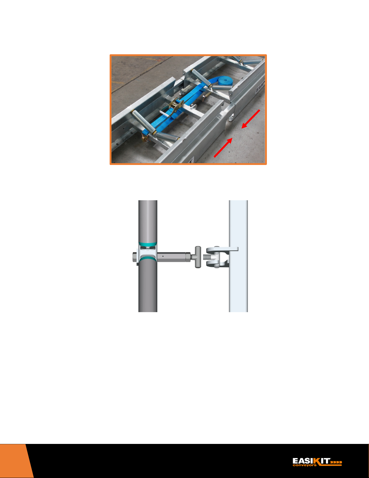
Push or pull sections together with the use of a sash clamp or ratchet strap if required and line up T bolt
3.
toggle with hooks in the center of the section.
Adjust T bolt toggle by means of a 24mm spanner until it is located onto the hooks and then tighten back
4.
until sections are firmly together.
If your conveyor has been supplied with strengthening stringers you will need to start fixing them to the
5.
conveyor at this stage. These are supplied in 2.4m lengths and will need to be bolted to the underside
of the conveyor frames spanning 1.2m either side of the joint. These should be fitted with the open ‘C’
side of the stringer facing outwards to enable access to tighten bolts.
If your conveyor modular length includes a 1.2m section then two half lengths of 1.2m
a)
stringers will have been supplied as infill pieces – bolt one of these either side of the
conveyor to the underside of the Base Tension Unit so that the ends are flush with the
start of the 1.2m section.
10
EK600 INSTRUCTION MANUAL
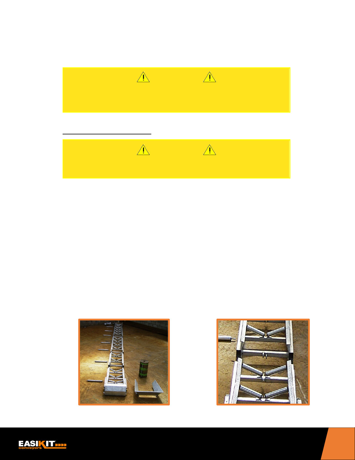
b) If your conveyor only has 2.4m sections then bolt the first two stringers (one either side of the
conveyor) to the underside of the Base Tension Unit so that they are overlapping the section by
exactly 1.2m as shown in the picture below:
6. Continue adding intermediate sections as described in 2, 3 and 4 above, until the desired length of
your conveyor is achieved.
Couple Head Unit to the last intermediate section as described in 2, 3 and 4 above.
7.
Note: Do not fit the hopper at this stage.
Note: You will find it more advantageous to fit the belt next, prior to fitting the motor and gearbox.
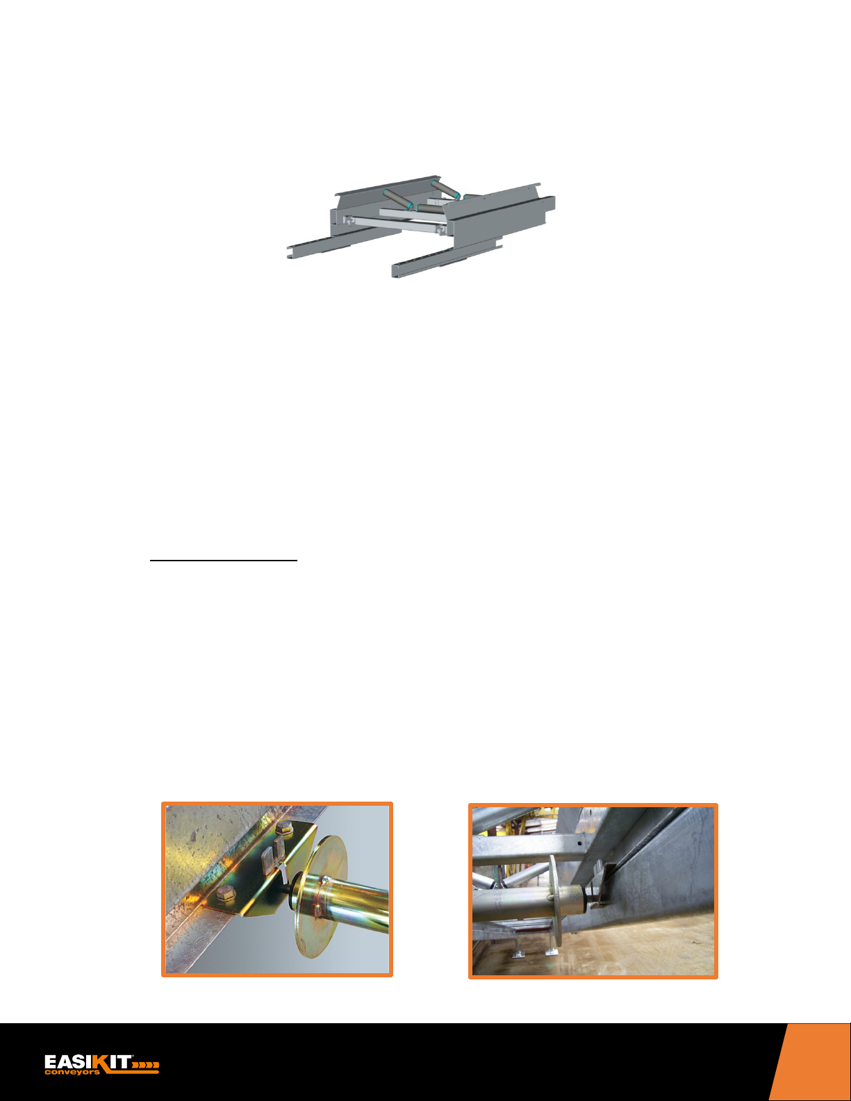
6.3 RETURN ROLLERS
STANDARD RETURN ROLLERS
These come supplied loose and will need to be fitted in the underside of the conveyor frame in the
slots in the framework.
DISC RETURN ROLLERS
If your conveyor has been supplied with Disc Return Rollers they will come with the necessary
brackets and fixings. The brackets should be fitted inside of the conveyor frame on the underside,
over the standard return roller lugs in pre-drilled holes and bolted securely. If stringers are used, it
will not be necessary to use the bolts. The rollers are then slotted into these brackets as shown.
Disc Return Rollers fitted without stringers Disc Return Rollers fitted with stringers
11
EK600 INSTRUCTION MANUAL
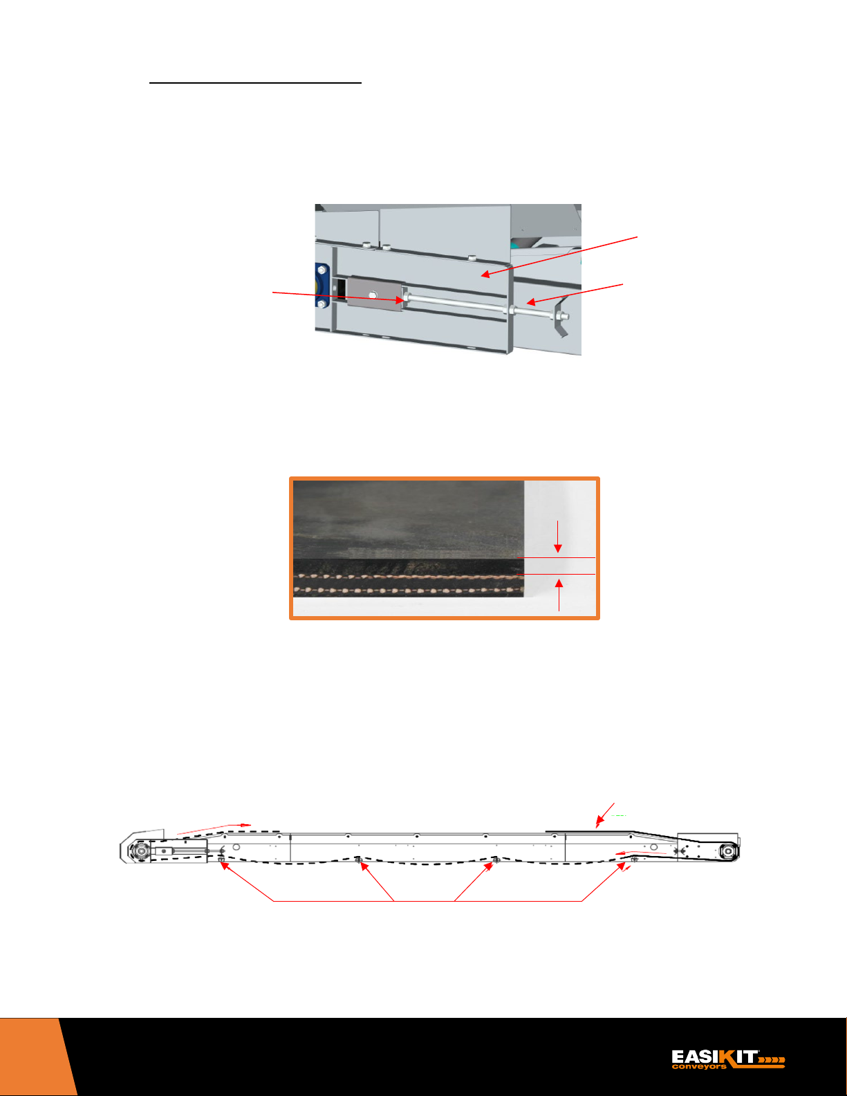
6.4 FITTING BELT – CLIP JOINT
Top Cover
(C)
(B)
(A)
1. Ensure that the drum on Base Tension Unit is as far forward (towards motor end) as
possible, slacken off clamp bolt (A), release adjusting nuts (B) and repeat on the opposite
side. Next slide the tail drum frame (C) along the conveyor frame to the minimum belt length
position.
Adjusting nuts
2. Ensure that the belt is the correct way up. Your belt is constructed with several layers of
rubber and fabric ply. It is important that the thickest ply is facing upwards as this is the
wearing surface.
Tail drum frame
Clamp bolt
3. Feed one end of the belt into the conveyor frame over the return rollers at one end of the
conveyor, ensuring that the belt is the correct way up with the wear surface facing
downwards and running on the return rollers.
4. Pull belt over the top of the return rollers down towards the opposite end of the conveyor.
BELT
RETURN ROLLERS
12
EK600 INSTRUCTION MANUAL
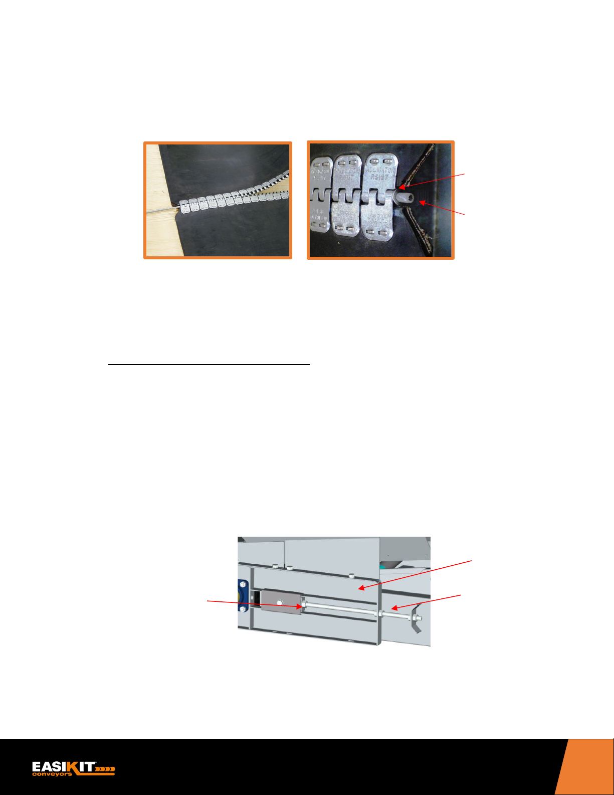
5. Pull belt around the head and tail drums and onto the top of the conveyor over the top
(C)
(B)
(A)
rollers to meet the opposite end of the belt.
6. Interlock belt fasteners and insert hinge pin. Clamp the washers either end, to prevent
hinge pin movement. Ensure that the ends of the hinge pin are within the width of the
conveyor belt. This may need to be cut if needed.
Washer
Clamped
End of hinge
pin within the
width of belt
7. Make sure belt is lined up in the center of head and tail drums. The belt should now be
tensioned following the tensioning procedure as described in Section 6.11.
6.5 FITTING BELT – VULCANIZED JOINT
In normal circumstances it is more advantageous to fit the belt as above and vulcanize the belt joint
when the conveyor is ready assembled. However, if this is not possible, the instructions below are
a guide to fitting a pre-vulcanized endless belt to your conveyor after the sections have been fitted
together.
1. Ensure that the drum on Base Tension Unit is as far forward (towards motor end) as
possible, unwind the Adjusting Nuts (A) repeating on the opposite side. This will slide the tail
drum (B) along the conveyor. Continue until drum is as far forward as possible to provide
the minimum belt length position.
Adjusting nuts
Tail drum frame
Clamp bolt
2. Remove the tail drum guard on base tension unit. (Code no 36520 on EK600 Base Tension
Unit exploded drawing –see page 49). This can be removed using two open ended
spanners.
13

EK600 INSTRUCTION MANUAL
3. Remove all return rollers on the underside of your conveyor by lifting them out of their slotted
brackets. (If a Snub Drive Head unit is supplied you will also need to remove the snubbing
roller, Code 36613 on exploded drawing shown on page 51, by unbolting the bearings using
two open ended spanners).
4. Roll out belt to its full length alongside of the assembled conveyor.
5. Lift one end of the belt up and loop over the tail drum of the base tension unit. This should
be carried out with a minimum of two people.
6. Mechanically lift one side of the conveyor to enable the belt to be fed through under the
conveyor frame and over the temporary support trestles. As the belt is being inserted,
replace the return rollers in turn along the length of the conveyor to support the belt.
7. Loop the other end of the belt over the head unit drum.
Useful Hint:
In some instances where access is tight or difficult, it may be advantageous to
dismantle and remove the head drum from the head unit. This can be achieved by
simply removing one drive drum mounting plate (code 345113/4 on EK600 Head Unit
exploded drawing on page 49 or code 36152/3 on EK600 Snub Drive Head Unit on
exploded drawing on page 51). The drive shaft grub screws in the bearing will need
to be released on both sides and the drum removed from the head unit. Once the belt
has been positioned in place, the drum can be reassembled into the head unit in
reverse procedure of removal. It is important to ensure that the drum is repositioned
centrally and the grub screws are tightened securely.
8. Ensure that the belt is centrally positioned on the head and tail drums and along the length
of conveyor both top and underside. (If a Snub Head Unit has been supplied you will need
to re-insert the snubbing roller that was removed earlier).
9. Replace the tail drum guard in reverse procedure to how it was removed using two open
ended spanners to re-tighten the fixings.
10. The belt should now be tensioned following the tensioning procedure as described in
Section 6.11.
14
EK600 INSTRUCTION MANUAL
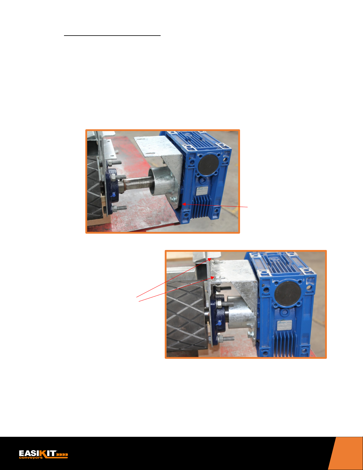
6.6 FITTING MOTOR & GEARBOX
The motor can be fitted to the conveyor at this stage. Alternatively, if your conveyor will be supported
on stands, you may prefer to fit the motor once the conveyor installation is complete. If this is your
choice, refer to Section 6.7 (Fitting EASIKIT® Support Stands) prior to carrying out the instructions
below.
Ensure that the drive shaft is clean and lubricated with a ‘copper slip’ type lubricant prior to
fitting the motor. It is recommended to first loosely position the motor mounting bracket to
the gearbox and then align the motor onto the drive shaft prior to bolting onto the mounting
bracket. (N.B. The motor body should be parallel to the conveyor, do not mount it vertical).
Carefully align fixing holes and secure and tighten evenly.
Loosely position the
motor mounting bracket
to the gearbox
Align the motor
onto the drive
shaft and bolt onto
the mounting
bracket
15
EK600 INSTRUCTION MANUAL
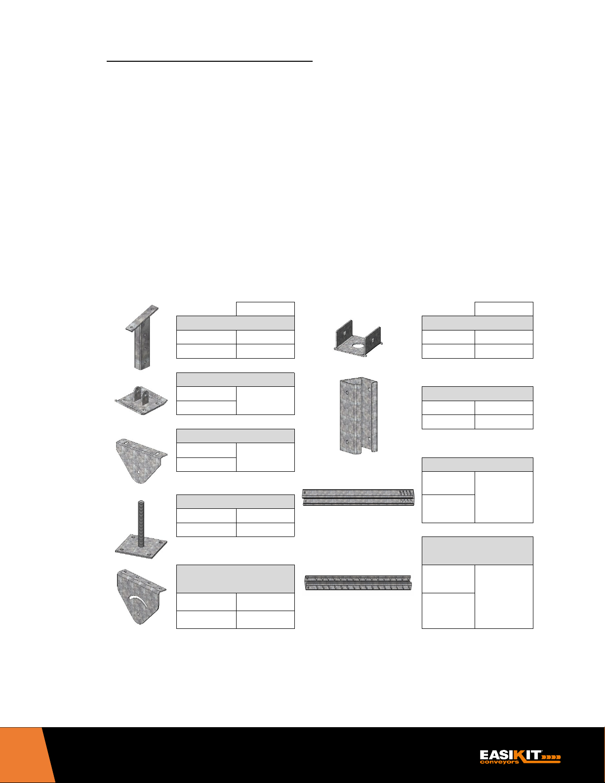
6.7 FITTING EASIKIT® SUPPORT STANDS
Part No.
Part No.
HD Stand 1 Foot
Base Plate
Inner
500935
MD
500235
Outer
500936
HD
500224
HD Stand 1 Foot Base
MD
Joiner
HD
MD
500234
HD
500223
Brace Fixing Bracket
MD
HD Brace Outer
Adjustable Foot
MD
500236
HD
500225
MD
500239
HD
30163C
There are two models of EASIKIT® support stands available – either Heavy Duty or Medium Duty.
Both are manufactured and constructed on the same design and are adjustable.
It is essential that all conveyors are adequately supported underneath feed points.
For both types of stands, it will be necessary to use mechanical means of handling whilst fitting the
stands (see Section 5 – Lifting & Supporting).
Normally stands are supplied assembled and will just require fitting under the conveyor on-site.
However, the first part of these instructions allows for assembling the individual stand components if
these have been supplied loose.
SUPPORT STAND COMPONENTS
Smiley Bracket MD
30166A
500230
MD
HD
Brace Inner
HD
500228
500229
16
EK600 INSTRUCTION MANUAL
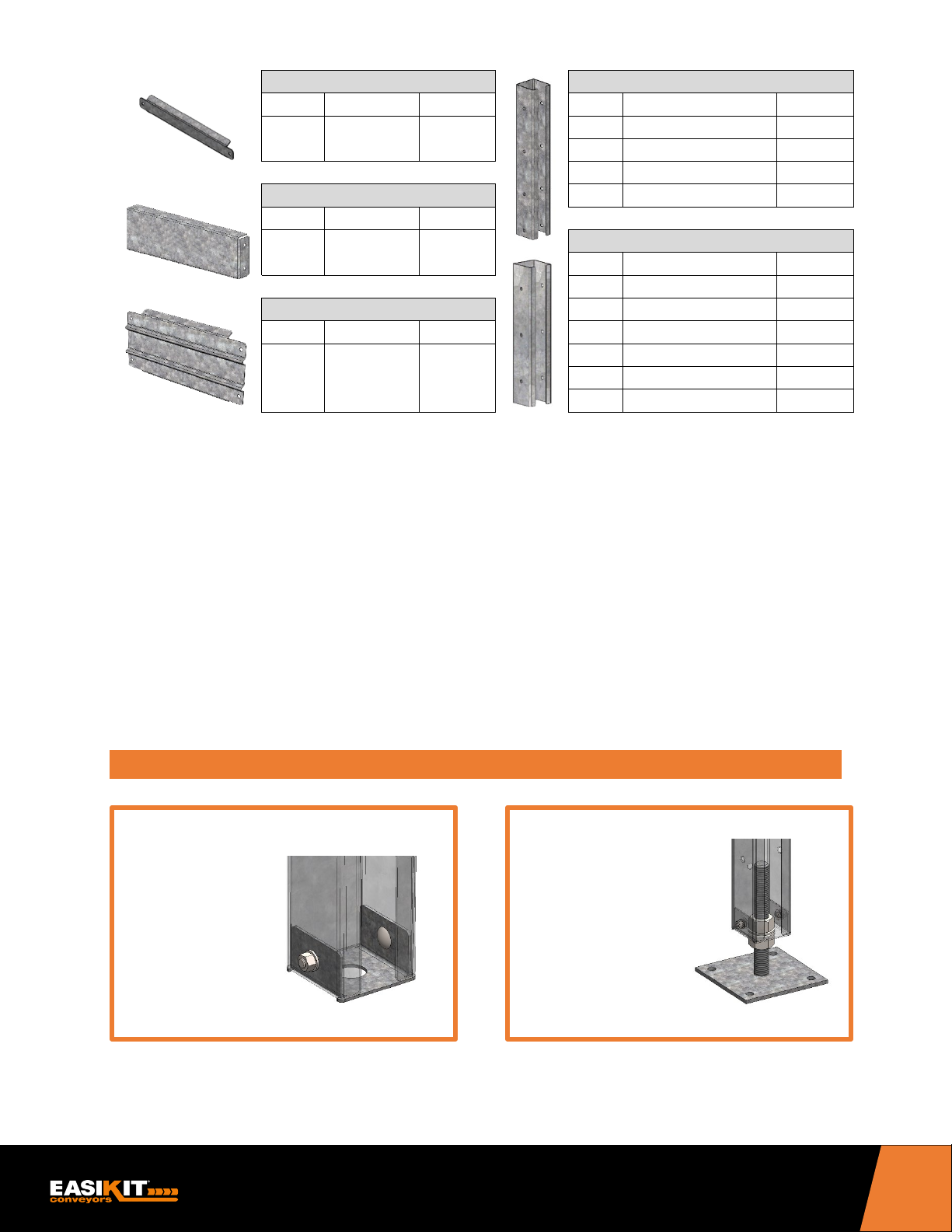
Cross Brace – MD Stand 1
Inner Leg
Type
Plate Width
Part No.
Type
Size
Part No.
EK600 565mm 500872
MD
60 x 40 x 600mm
500571
HD
93 x 93 x 600mm
500569
MD
60 x 40 x 1200mm
500233
Cross Brace – HD Stand 1
HD
93 x 93 x 1200mm
500222
Type
Plate Width
Part No.
Outer Leg
Type
Size
Part No.
MD
67 x 47 x 515mm
500572 Cross Brace – Stand 2-7
HD
100 x 100 x 515mm
500570
Type
Plate Width
Part No.
MD
67 x 47 x 1200mm
500231
HD
100 x 100 x 1200mm
500222
MD
67 x 47 x 2400mm
500232
HD
100 x 100 x 2400mm
500221
STEP 1
STEP 2
EK600 522mm 500609
EK600 565mm 500241
In addition to the above components each stand includes the following fixings complete with
relevant washers and nylock nuts: -
• M8 x 85mm Bolts
• M10 x 25mm Coach Bolt
• M12 x 30mm Bolts
• M12 x 100mm Bolts (MD)
• M12 x 130mm Bolts (HD)
• M16 Nuts (MD)
• M30 Nuts (HD)
Each stand is supplied with a complete list of components to enable the stand to be assembled.
Check that you have the correct parts against the packing list before proceeding.
EASIKIT® SUPPORT STANDS ASSEMBLY INSTRUCTIONS
Fit Base Plate
to Inner Leg
Fixings:
• M10 x 25 mm
Coach Bolt
Fit Adjustable Foot
to Base Plate
Fixings:
• M16 Nut (MD)
• M30 Nut (HD)
17
 Loading...