

Page 1
38
CALLER ID HANDSFREE
HEADSET BUSINESS
TELEPHONE
MODEL IQ335
OPERATING INSTRUCTIONS
Page 2

40
CONTENTS
1. FEATURES ...................................................................................................................................... 1
“HEADSET SAVVY” FEATURES ....................................................................................................................1
CALLER ID (CLI) FEATURES .........................................................................................................................1
GENERAL FUNCTIONS .................................................................................................................................2
OPERATING REQUIREMENTS......................................................................................................................3
LIQUID CRYSTAL DISPLAY............................................................................................................................3
MESSAGE WAITING ......................................................................................................................................3
2. SETTING UP.................................................................................................................................... 4
UNPACKING ...................................................................................................................................................4
GENERAL SETTING-UP ................................................................................................................................4
LINE CONNECTION .......................................................................................................................................4
DISPLAY CONTRAST ADJUSTMENT............................................................................................................4
DA TE AND TIME SET UP DISPLAY................................................................................................................4
BASIC OPERATION........................................................................................................................................6
3. GENERAL CONTROLS AND INDICATORS ................................................................................... 7
RINGER/MESSAGE WAITING INDICATOR ...................................................................................................8
RINGER VOLUME SWITCH ...........................................................................................................................8
RINGER PITCH CONTROL ............................................................................................................................8
ALPHA-NUMERIC KEYPAD ........................................................................................................... ................ 8
RESET BUTTON.............................................................................................................................................8
CRADLE SWITCH ..........................................................................................................................................9
VOLUME
and VOLUME KEYS ..............................................................................................................9
RECALL KEY ..................................................................................................................................................9
REDIAL KEY ...................................................................................................................................................9
To redial last number................................................................................................................................................................ 9
To direct redial the last number................................................................................................................................................ 9
P AUSE FUNCTION........................................................................................................................................10
For manual dialing ................................................................................................................................................................. 10
MUTE KEY AND INDICATOR......................................................................................................................... 10
HANDSFREE/HEADSET KEY AND INDICATOR ..........................................................................................10
To use Handsfree mode ......................................................................................................................................................... 10
To use Headset mode ............................................................................................................................................................ 10
CURSOR AND KEYS...........................................................................................................................10
AUTOMA TIC CALL TIMER .............................................................................................................................10
DATA PORT................................................................................................................................................... 10
BA TTERY COMPARTMENT.......................................................................................................................... 11
DISPLA Y ICONS AND FIELDS ...................................................................................................................... 11
4. HANDSFREE OPERATION........................................................................................................... 13
Incoming calls using Handsfree ............................................................................................................................................ 13
Outgoing calls using Handsfree (manual or memory dialing)............................................................................................... 13
Changing from Handsfree to Handset during a call ............................................................................................................... 13
Changing from Handset to Handsfree during a call ............................................................................................................... 13
Page 3

41
5. HEADSET OPERATION ................................................................................................................ 14
BASIC OPERA TION......................................................................................................................................14
HEADSET/HANDSET/HANDSFREE MODES .............................................................................................. 14
TRAINEE/SUPERVISOR MODE...................................................................................................................14
Silent Ringing ......................................................................................................................................................................... 14
ALERT LIGHT SUPPORT ............................................................................................................................. 15
6. MEMORY OPERATION.................................................................................................................. 16
MEMORY STORAGE .................................................................................................................................... 16
Memory Backup ..................................................................................................................................................................... 16
Memory Storage ..................................................................................................................................................................... 16
DIRECT ACCESS MEMORY KEYS ..............................................................................................................16
Direct Access Memory Capacity............................................................................................................................................. 16
Speed-Dialing (Storable Handsfree code)............................................................................................................................. 16
Speed-Dialing and Automatic Hang-up ................................................................................................................................. 17
To view the contents of a Direct Access memory................................................................................................................... 17
To store a Number and Name in a Direct Access memory................................................................................................... 17
To dial from a Direct Access memory .................................................................................................................................... 17
Direct Access Memories and the Memory Protect Switch ...................................................................................................... 18
To progr am or alter the contents of a protected Direct Access memory ................................................................................ 18
To dial from a Protected Direct Access Memory .................................................................................................................... 19
DIRECTORY MEMORY ................................................................................................................................19
Scrolling ( ) and Editing ( ) keys ........................................................................................................................ 19
Directory Memory Capacity .................................................................................................................................................... 19
To Store a Number and Name into a Directory memory ....................................................................................................... 20
To dial from the Directory memory using Name Search ....................................................................................................... 20
To edit an entry in the Directory memory ............................................................................................................................... 20
To delete an entry from Directory memory............................................................................................................................. 20
LAST NUMBER REDIAL MEMORY ............................................................................................................... 21
Using the 5-Stack Last Number Redial Memory ................................................................................................................... 21
7. USING THE CALLER ID DISPLAY................................................................................................ 22
CALL WAITING DISPLA Y .............................................................................................................................23
Calls list .................................................................................................................................................................................. 23
Scrolling (
) keys .......................................................................................................................................................... 23
To view the Calls List and dial a Number in the Calls List ..................................................................................................... 23
To store a caller’s details in a Direct Access memory from the Calls List ............................................................................. 25
To store a caller’s details in the Directory memory from the Calls List.................................................................................. 25
To delete a Call from the Calls List or to delete the entire Calls List ..................................................................................... 25
8. AD VANCED NETWORK OPERA TION.......................................................................................... 26
Message Waiting function in conjunction with Telstra’s Customnet, Home Messages 101 services and MessageBank..... 26
Manually Resetting the Message Waiting Prompts ................................................................................................................ 26
“Talking Text” SMS Messages ................................................................................................................................................ 26
HOLDING AND TRANSFERRING CALLS......................................................................................................26
P AUSE FUNCTION WHEN DIALING O UT .....................................................................................................26
AUTOMA TIC TRUNK ACCESS DIGIT INSERTION .......................................................................................26
Automatic Pause Insertion ..................................................................................................................................................... 27
P AUSE TIME..................................................................................................................................................27
HOLDING AND TRANSFERRING CALLS......................................................................................................28
USING THE MEMORIES................................................................................................................................28
Speed Dialing......................................................................................................................................................................... 28
Cascade Memory Dialing ....................................................................................................................................................... 28
Page 4

42
9. INSTALLATION.............................................................................................................................. 29
GENERAL SETTING-UP ...............................................................................................................................29
LINE CONNECTION...................................................................................................................................... 29
LOCATION..................................................................................................................................................... 29
WALL MOUNTING..........................................................................................................................................29
TECHNICAL ADJUSTMENTS - FOR CORRECT OPERA TION....................................................................31
RECALL TIMING SELECTION .......................................................................................................................31
MESSAGE WAITING LIGHT COMPA TIBILITY ................................................................................................31
HEADSET MIC ADJUST CONTROL ............................................................................................................. 31
To make a Headset mic level adjustment .............................................................................................................................. 31
HEADSET POLARITY SWITCH....................................................................................................................32
TABLE 1 ............................................................................................................................................................ 33
10. GENERAL CARE AND MAINTENANCE..................................................................................... 34
CLEANING.....................................................................................................................................................34
FAILURE T O OPERA TE AND SERVICE DIFFICULTIES ...............................................................................34
11. THUNDERSTORMS.................................................................................................................... 35
12. SERVICE .....................................................................................................................................36
13. WARRANTY: 3 YEARS PARTS & LABOUR ..............................................................................36
Page 5

1
1. FEATURES
“HEADSET SAVVY” FEATURES
• Auto detect circuitry disables handsfree when headset is in use
• Mute key for headset microphone
• Electronic earpiece volume control
• Built-in headset amplifier suits a wide range of headset types
• Headset mic adjustment allows any headset mic type
• Headset cable polarity switch suits any headset cord
• ”Silent Ringing” mode selectable so that incoming calls ring only in the headset
to reduce office noise
• Trainee/Supervisor “Double Jacking” mode
• Change between headset, handsfree and handset modes during a call
• Built-in acoustic shock protection
• Compatible with “Talking Text” SMS services
CALLER ID (CLI) FEATURES
• Compatible to Bellcore GR-30-CORE Caller ID standard
• Supports Type 2 Caller I D Call Waiting (CIDCW) during a call
• Supports Telstra’s Flashing Message Indicator for Home Messages 101 and
MessageBank
• Large Liquid Crystal 3-line Display
• Receives and displays caller’s name and number
• Saves 80 callers’ names (16 characters) and numbers (32 digits)
• Date/Time stamp of each call in 24-hour format
• New call, Repeat call indication
• Answered/Unanswered indication of incoming calls in Calls list
• Delete a single call or all information from the Calls list, Directory and Redial
memories
• Blinking Calls LED indicates a new incoming call and/or Message Waiting
• On-screen Message Waiting indicator
Page 6

2
GENERAL FUNCTIONS
• Alpha-numeric keypad
• Direct redial allows immediate redialing of the la st number without hanging up
• Redial any of the last 5 dialed numbers
• 20 Direct Access memories, 10 one-touch and 10 two-touch accessible via 10 keys; capa city 32 number
digits and 16 name characters
• 80 Calls list memories; ca pacity 32 number digits and 16 na me characters
• 100 Directory memorie s; capacity 32 number digits and 16 name characters
• Date and T ime display
• Automatic call duration timer
• User selectable T i med-bre a k Recall: 100ms, 200ms, 300ms and 600ms. Factory set to 100ms
• User selectable Pause timings of 100ms and 1 second. Factory set to 1 second
• Manual a nd storable pause
• User selectable High/Low/Off ringer volume control
• User adjustable ringer pitch control
• Visual ringer indication with high voltage message waiting and BP250 message waiting built-in (see
Caller ID section for details of Centrex message waiting)
• Mute key with LED visual indicator
• Handsfree/Headset key with LED indicator
• Switch between Handsfree, Headset and Handset modes mid-call
• Volume control (handset and headset earpieces and handsfree speaker)
• The Calls list, Directory and Direct Access memories are non-volatile (no batteries needed)
• EEPROM memory allows mass pre-programming of the 5 uppermost Direct Acce ss memory keys to
create network feature a ccess keys
• Desk or wall mountable
• On-screen warning icons to indicate “Low Battery” and “Adaptor Failure” power conditions
• Data port provides access f or computers, a n swering ma chine s a nd cordless phone s
Page 7

3
OPERATING REQUIREMENTS
• Any 2-wire analog line; if the IQ335’s Caller ID f eature is required, please ensure that your line
delivers the necessary Caller ID data
• 240V mains outlet for 9V mains power adaptor (supplied) for full support of all functions
• If 3 x AA Alkaline batteries (not supplied) are fitted in the absence of mains adaptor or during mains
power failure, they can provide up to one month’s support of all functions
• If no adaptor or battery power available - basic telephone operation (will automatically power up
approximately 1 second after lifting handset)
• Memory backup - no batteries required. All memorie s (except the Redial memory) are non-volatile; the ir
contents will be retained without any power
LIQUID CR YSTAL DISPLAY
• Liquid Crystal Display with a row of useful icon indicators, a number field and a name field (16
characters each)
MESSAGE WAITING
The following types are supported:
• P ABX compatible to 80V DC sign al with red LED indicator - some systems require the fitting of optional
circuitry
• Polarity reversal (e.g. Ericsson BP250) message waiting light built-in with red LED indicator
• Bellcore (e.g. Telstra Spectrum, Cisco a nd Nortel DMS) with both on-screen and LED indicators
• Type 2 Caller ID Call Waiting (CIDCW) during a call
Page 8

4
2. SETTING UP
UNPACKING
The carton contains the following:
• Telephone body and handpiece
• Coiled handset cord and line cord
• 9V DC adaptor
• Quick Start Guide
GENERAL SETTING-UP
1. Fit the coiled cord to the appropriate sockets in the handset and in the telephone base - please do
not connect the coiled cord into the headset jack
2. Fit the line cord to the rear socket and to your telephone network outlet
3. Set the Ringer Volume and the Ringer Pitch controls
4. Lift the handset to check for dial tone and to wake up the display
5. If using a headset, connect it to the hea dset ja ck (see Figure 2B)
6. Fit the adaptor plug to the 9V DC Jack a nd plug in the adaptor to a mains power outlet
7. Follow the instructions below for general installation
8. See section 9 for other installation instructions a nd technical settings.
LINE CONNECTION
This telephone is supplied with a line cord and plug compatible with 8 pin modular (RJ45) wall sockets,
with the centre pair being used for all telephony function s. Some units may be supplied with a n advanced
type plug compatible with both 8 pin and 6 pin modular wall sockets as standard. Other types of plugs
and cords are available on request.
DISPLAY CONTRAST ADJUSTMENT
Certain background lighting conditions may cause the display to show unlit characters. To set optimum
display performance for your telephone, make sure that the telephone is on-hook and in an idle state.
Press STORE followed by (“VOL+”) and (“VOL-”) keys to achieve the best contra st f or your lighting
conditions.
DATE AND TIME SET UP DISPLAY
The best time to set up the Date and Time is during installation, as follows:
Upon installation the display will automatically show step by step prompts to guide you through the
Date and Time setup procedure. This procedure can also be used at any time to change the time and
date settings. The following procedure assumes that all steps in the “General Setting Up” have been
carried out.
If you subscribe to a Caller ID service, the clock may automatically be synchronised to the network’s
clock when the telephone receives its first incoming call containing Caller ID data.
Page 9
5
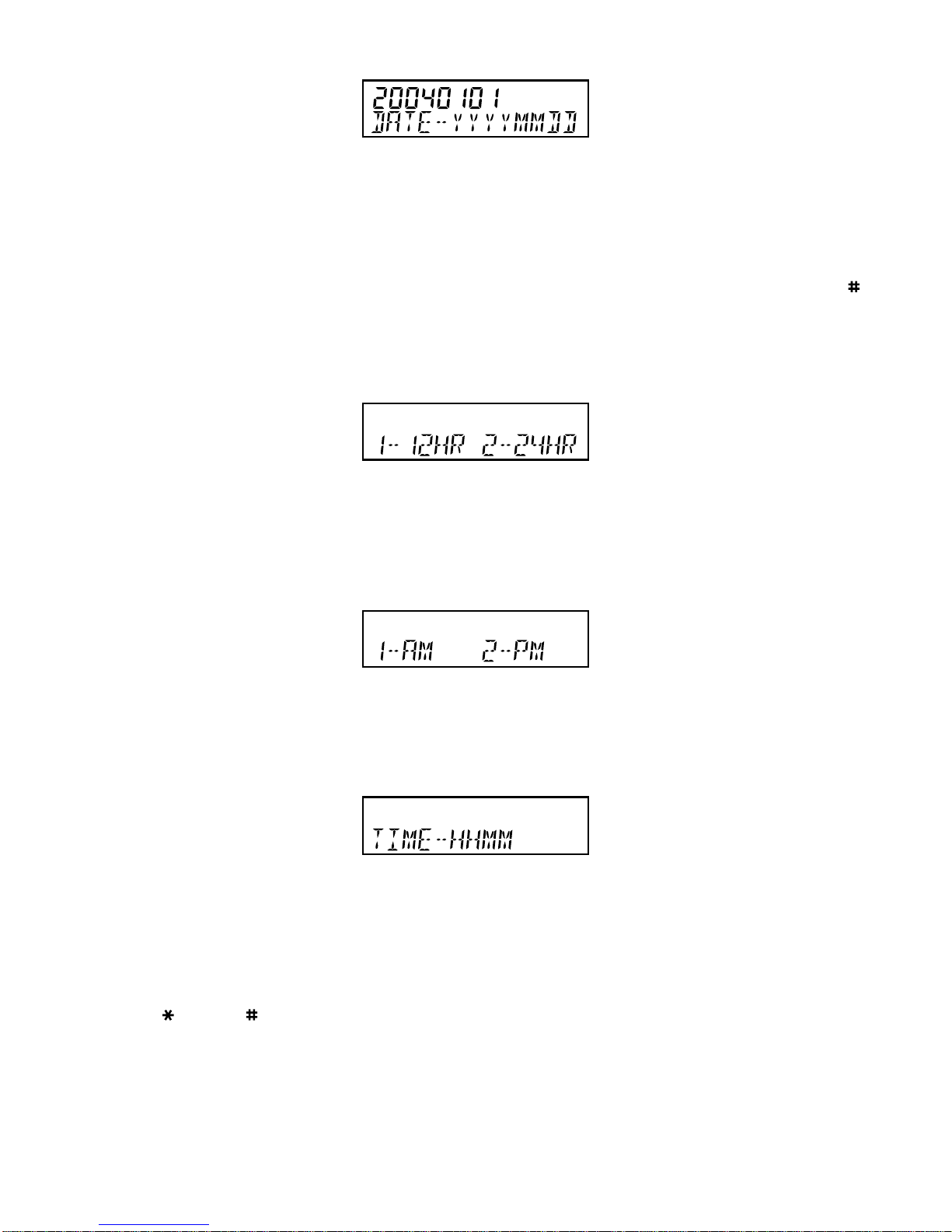
FIGURE 1A: DATE SETTING
1. If the display is blank, lift the Handset briefly to wa ke up the telephone. Repla ce the Handset in the cra dle
2. For 10 seconds the display will show “20040101” and “DA TE-YYYYMMDD” when the unit is first powered
up
3. If the display is alive but not showing “20040101” and “DA TE-YYYYMMDD”, press ST ORE and then ;
the display will return to the “20040101” and “DA TE-YYYYMMDD” mode. Proceed to step 4 within the
next 10 seconds; repeat step 3 if nece ssary to re-enter Date/Time setting mode
4. Enter Y e ar (4 digits), Month (2 digits) a nd Date (2 digits)
FIGURE 1B: HOUR MODE SETTING
5. Hour Mode Setting - the display will now show “12-HR 24-HR”
6. Press 1 for 12 hour mode or 2 for 24 hour mode display (if 24 hour mode was chosen, please go to
step 9)
FIGURE 1C: AM/PM SETTING
7. If 12-hour mode was selected above, the display will show “1-AM 2-PM”
8. Press 1 or 2 to select AM or PM time display
FIGURE 1D: TIME SETTING
9. The display will show “TIME-HHMM” after completion of the hour mode setting
10.To set the current time enter 2 digits for the hour, followed by two digits for the minutes
11.The display will show “CLOCK STORED” and the date and time will be updated.
Note: use key and key to change any incorrect entries while carrying out the above procedure.
Page 10

6
BASIC OPERATION
The IQ335 can be used in the same way as a normal telephone; simply lift the handset to answer an
incoming call, or lift the handset and dial on the keypad to commence an outgoing call. Please refer to
other sections for more about Handsfree, Headset, Caller ID display and Memory operations. The
telephone will also operate in a ba sic mode when mains power has failed and if batteries have not been
fitted (the telephone will automatically power up approximately 1 second after lifting handset). If 3 x AA
alkaline batteries (not supplied) are fitted in the absence of mains adaptor or during mains power
failure, they can provide up to one month’s support of all functions.
Page 11

7
3. GENERAL CONTROLS AND INDICATORS
FIGURE 2A: TOP VIEW
FIGURE 2B: BOTTOM VIEW
Page 12

8
RINGER/MESSAGE W AITING INDICATO R
Located at the top right hand side of the telephone above the display, the red lense contains two
different indicators; their functions are as follows:
1. Ring Indicator Flashes when the telephone rings with an incoming call.
2. PABX Message Waiting Indicator Illuminates when a message is waiting in your PABX voicemail
system (depends on system compatibility). The built-in
message waiting option suits any neon type (minimum
80 VDC) message waiting system and polarity reversal
message waiting (other system types are available as optional
extras). To determine which PABX type your IQ335 ha s been
prepared to suit, check the telephone’s underside for a label
indicating that specific circuitry has been installed in your unit.
If in doubt, contact Interquartz for further details. To retrieve
your message, consult your voice mail system user guide.
IQ335 is also fitted with a message waiting indicator which is compatible with the voicemail features of
Centrex networks (e.g. Telstra Customnet) and residential line voicemail systems (e.g. Telstra Home
Messages 101 and MessageBank). There are indicators located in the CALLS Key and the display for
these services and are described elsewhere in this manual.
RINGER VOLUME SWITCH
The three available positions allow selection Off (no sound), Low volume, and High volume of the
telephone ringing sound during an incoming call (Figure 2B).
RINGER PITCH CONTROL
The pitch of the ringing sound may be altered by rotating the control to suit your preference to achieve
a distinctive sound, or one that is audible, more distinctive or more pleasant.
ALPHA-NUMERIC KEYPAD
In addition to normal dialing, the alphabetic characters are provided on the keys to enter names in the
Direct Access and Directory memories as well as any online applications that require alphabetic
keystrokes.
RESET BUTTON
Press to restore normal operation of the telephone in case of a malfunction or lock-up. The memories
will not be erased when this button is pressed.
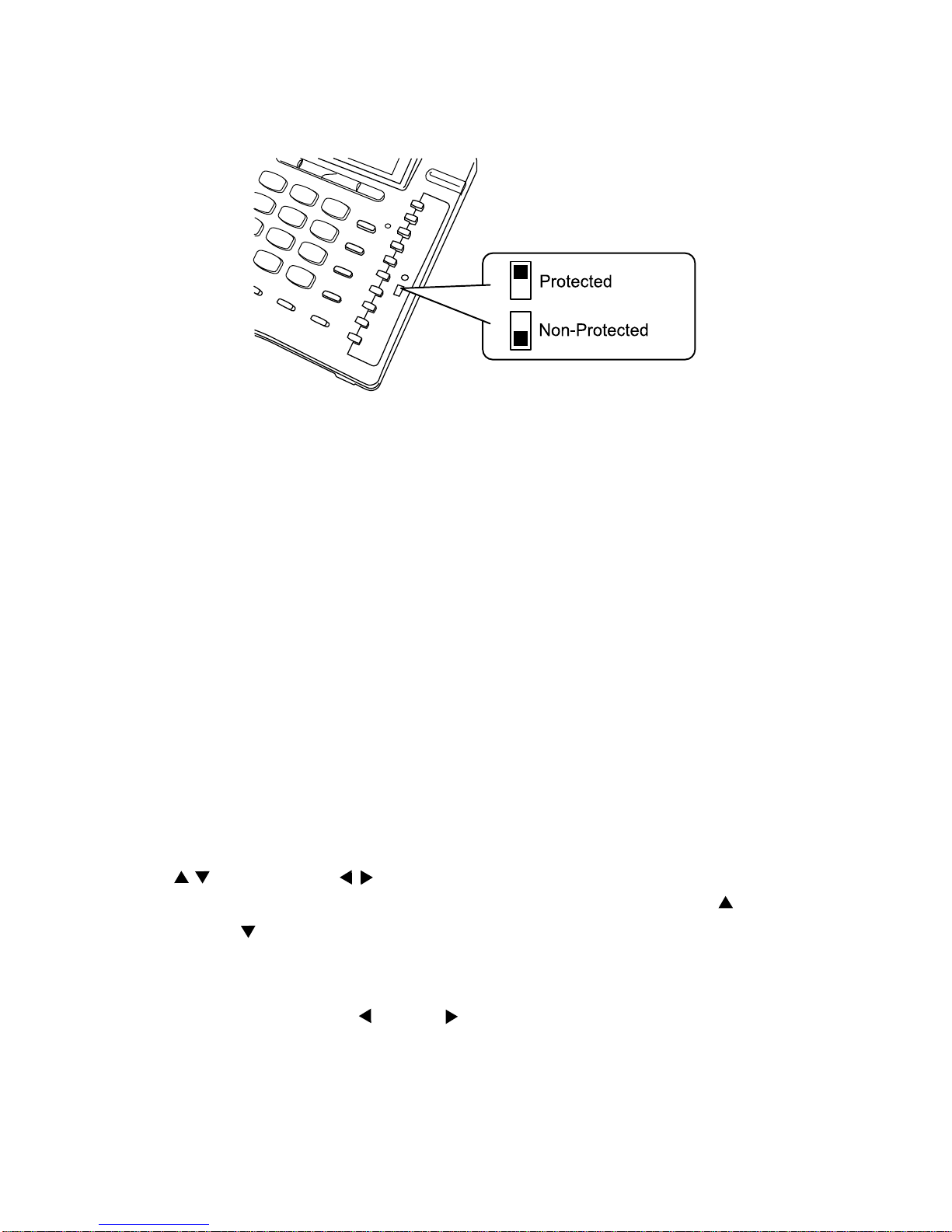
The RESET button should also be pressed when the Memory Prote ct Switch (illustrated) is moved to a
new setting.
Page 13

9
CRADLE SWITCH
Located in the handset cradle, this plastic lever is depressed by the handset (when placed in the cradle)
to cut off the line. Note: Depressing this cradle lever too briefly when intending to terminate a call may
result in a n a ccidental “hookflash” that will inadvertently pla ce the call on hold - this is known as “phantom
calls” because the held call may ring again at your extension within a few minutes (the other party will
have hung up, so it will seem as if you were called by a phantom, hence the name “phantom calls”). If
you experience this problem, when terminating your call please depress the cradle lever a little longer
before making/receiving your next call (i.e. phantom calls are not a system or telephone fault).
VOLUME and VOLUME KEYS
Used to adjust the hearing level of the handset earpiece, the handsfree speaker and the headset. To
adjust the volume, press the VOL+ ( ) and Vol- ( ) buttons located under the display (see Figure 2A).
Adjustment during a conversation will not be detected by the other party.
RECALL KEY
For use with a host system to invoke special system or network facilities such as call-hold or call
transfer which may be available in your network. It is sometimes referred to as the “Flash” key or
“Facility” key. To learn how to use it, please consult your telephone host system manual. Recall timing
is preset to 100ms. The Recall timing setting affects the Recall key’s ability to function correctly with
your system (see the Installation section regarding this setting).
REDIAL KEY
Press to redial the last number dialed, which may be up to 32 digits long. When pressed while still online, the telephone will clear the call and retry the number. It can be used in Handset, Handsfree, and
Headset modes. Dialing more than 32 digits during one call will cause erasure of the entire number from
the Redial memory.
See further details of the 5-stack Last Number Redial memory in section 6 “Memory Operation”.
To redial l ast number
1. Lift Handset, or press HANDSFREE/HEADSET
2. Press REDIAL
3. Press DIAL (telephone redials la st number).
To dire ct redial the last number
1. Lift Handset, or press HANDSFREE/HEADSET
2. Dial a number, [unsuccessful]
3. Press REDIAL; the telephone will automatically clear and re-connect the line; the number will be
re-dialed.
Page 14

10
PAUSE FUNCTION
The Pause command may be needed if your phone is connected to a ny network where a momentary pause
is required (e.g. a P ABX between intern al a nd extern al di al tones).
For manual dialing
1. Lift Handset
2. Dial any digits required before the pause
3. Press PAUSE; the telephone will complete the dialing process once the Pause time has elapsed
4. Dial the remaining digits.
The Pause function can be stored in any Direct Access or Direct memories. See section 8 for further
details.
MUTE KEY AND INDICATOR
When pressed, it cuts off transmission from the handset, headset and handsfree microphones to allow
user privacy. The red light indicates when the mute condition is active. Press MUTE again to release
the mute condition.
HANDSFREE/HEADSET KEY AND INDICATOR
The HANDSFREE/HEADSET key has an auto-detection function; which disables the handsfree mode
when a headset is in use. When the HANDSFREE/HEADSET key is pressed, a red indicator will glow
to show that the handsfree or headset mode is activated. Press the key again to turn it off.
To use Handsfree mode
Ensure that a headset is NOT connected to the headset jack. Press the HANDSFREE/HEADSET key;
the telephone will automatically operate in Handsfree mode. A red indicator will glow to show that the
Handsfree mode is activated. Press the key again to turn it off.
To use Headset mode
Connect a headset to the headset jack. Press the HANDSFREE/HEADSET key; the telephone will
automatically operate in Headset mode. A red indicator will glow to show that the Headset mode is
activated. Press the key again to turn it off.
CURSOR AND KEYS
The Cursor functions of the and keys can be used when it is necessary to use the same key twice
in succession when entering text and they also serve as Edit keys during memory storage.
AUTOMATIC CALL TIMER
When a call is in progress, the word TIMER appears on the display, a n d the time will count from 00:00.
To use the timer a s a call ti mer , the telephone will automatically enter the T i mer mode when commencing
a call. The call duration will be displayed for 10 seconds after the call is terminated.
DATA PORT
The Data Port provide s a cce ss to the telephone line f or computers (with a mode m), a n swering ma chine s
and cordless phones.
Page 15
11
BATTERY COMPARTMENT
As a precaution against the potential for a temporary interruption of mains power to affect the progress of
any ongoing call, 3 x AA al k aline batteries can be fitted to the compartment. They can provide up to one
month’s support of all functions while mains power is absent, and battery power will not be consumed while
mains power is present. If batteries have been fitted, it is recommended that they be routinely replaced
before the “best bef ore” date indicated by the battery manufa cturer (consult the pa ck aging or check on the
battery).
DISPLAY ICONS AND FIELDS
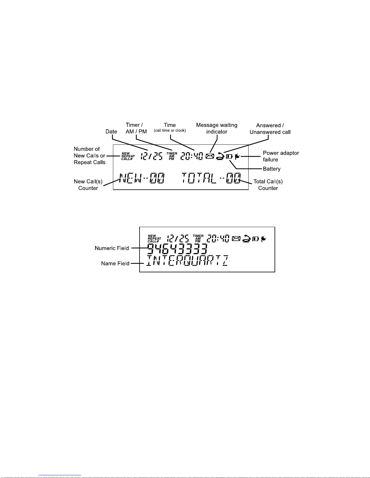
FIGURE 3A: DISPLAY IN IDLE STATE
FIGURE 3B: TYPICAL DISPLAY APPEARANCE WHEN SHOWING
DETAILS OF A CALL
Page 16
12
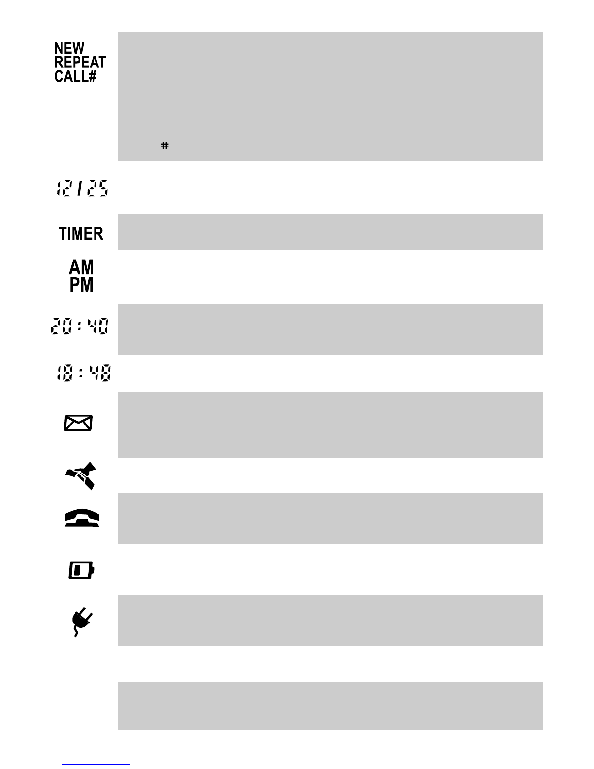
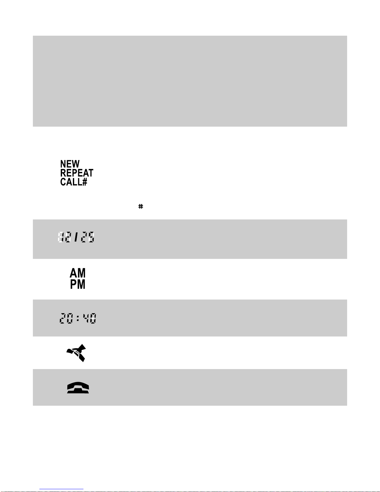
Received Call Status indication;
NEW - new calls have been received that have not previously been reviewed in the
Calls list (the Calls key will also be flashing)
REPEAT - indicates multiple calls have been received from the same caller in the
current Calls list’s history; therefore please note that only the most recent call from
that caller’s number will be retained in the Calls list.
CALL - entry number in Calls list
Date in Month/Day format; shows current date or date of received call when reviewing
Calls list
Indicates Call Timer is active
For the clock readout and when reviewing the time that a call arrived in the
Calls list (displays only in 12 hour mode)
Hour:Minute format for the clock readout and when reviewing the time that a call
arrived in the Calls list (displays only in 12 hour mode)
Minute:Second format in Call Timer mode (maximum count 99:59)
Displays together with “MESSAGE WAITING” text in the name field; to indicate the
presence of message waiting in voicemail system (see “Message Waiting Light
Compatibility” section)
Indicates, when reviewing the Calls list, that the call was answered on the IQ335
Indicates, when reviewing the Calls list, that the call was NOT answered on the
IQ335
If this symbol is visible, the 3 x AA Alkaline batteries in the battery compartment
should be replaced
Will be displayed in the absence of the adaptor power (only functions if batteries are
also fitted and are in good condition)
16 digits for displaying telephone number
16 characters for displaying caller name or number of new calls and total calls
received.
Number
Field
Name
Field
Page 17

13
4. HANDSFREE OPERATION
To commence a Handsfree call pre ss HANDSFREE/HEADSET; the telephone will activate the line, and
the speaker, and the indicator will switch on to provide confirmation. Dialing and speech can then
commence. Pressing the key again will terminate the call. The Handsfree state is storable in the Direct
Access memory keys – please see the MEMORY OPERATION section.
The Handsfree mode will be disabled if a hea dset is connected to the headset jack.
Incoming calls using Handsfree
1. Telephone rings
2. Press HANDSFREE/HEADSET
3. Commence your handsfree conversation.
Outgoing calls using Handsfree (ma nual or me mory di aling)
1. Press HANDSFREE/HEADSET
2. Dial required number or press desired memory key
3. Speak as necessary.
Changing from Handsfree to Handset during a call
Lift Handset and resume your conversation; the handsfree function will switch off automatically.
Changing from Handset to Handsfree during a call
1. Press HANDSFREE/HEADSET
2. Replace Handset
3. Resume your conversation in Handsfree mode.
HINTS FOR HANDSFREE OPERATION
As a courtesy, tell the other party that you are using the handsfree function. He/She may or may not
want people other than you to hear the conversation. A quiet environment ensures best handsfree
performance. When handsfree is used in a noisy room or near a noise generating device (for example,
a TV set), all or part of the message may be interrupted and ca nnot be heard. To elimin ate this proble m,
try to lower the noise level in the room.
During the handsfree conversation, your telephone will give priority to the person who speaks louder
when both people are talking simultaneously. Speak ON LY after the other person pauses or stops.
If the other person complains about poor tra nsmission, talk directly at your telephone and from a closer
distance as necessary, or lower volume control.
If the operation of the handsfree feature is not correct, refer to the FAILURE TO OPERATE section.
Page 18

14
5. HEADSET OPERATION
The IQ335 can be configured to suit many different headsets - please consult the INSTALLATION
section for details to get the best performance from your headset.
BASIC OPERATION
To make or receive call using the headset:
1. Press HANDSFREE/HEADSET
2. If you are making an outgoing call, dial the required number
3. To revert from Headset mode to Handsfree mode during a call from Headset mode, unplug the
headset
4. Speak as necessary
5. To hang up, press HANDSFREE/HEADSET.
HEADSET/HANDSET/HANDSFREE MODES
A call can be switched between modes as follows:
1. To revert to Handset mode from Headset mode, lift Handset
2. To revert back to Headset mode during Handset mode, press HANDSFREE/HEADSET.
TRAINEE/SUPERVISOR MODE
Allows the handset and headset to be used in tandem. This will enable a supervisor to monitor a
trainee’s progress during a call, or “take over” a call. The following procedures assume that the trainee
is wearing the headset and a call is in progress.
1. During a trainee’s call the supervisor may lift the Handset (Handsfree/Headset indicator will turn off)
2. Quickly press HANDSFREE/HEADSET and the indicator will illuminate
3. The trainee may continue the conversation with the supervisor only listening to the call.
Silent Ringing
Designed for call centres or any application where call-related noise is to be kept to a minimum, this
feature allows incoming calls to ring silently; the operator is aware of the incoming call, but the telephone
does not add to the room noise even when ringing.
To use the telephone in Silent Ringing mode:
1. Set the Ringer Volume switch to the Off position (signified by the square symbol without a bell
symbol inside it)
2. Put your headset on and wait for the next incoming call
3. When a call arrives, the Ringer/Message Waiting Indicator will flash and the operator will hear the
ringing tone at a low level in the headset
4. Press HANDSFREE/HEADSET to answer the call.
Page 19

15
ALERT LIGHT SUPPORT
The IQ335 is designed to support the “Alert Light” available on some headsets. When pressing
HANDSFREE/HEADSET on the telephone, the “Alert Light” indicator on the hea dset will be illumin ated,
signifying that the user is on a call. This feature can be used effectively in call centre applications so
that the user’s colleagues will be aware that the user has a call in progress.
Page 20

16
6. MEMOR Y OPERATION
MEMORY STORAGE
Model IQ335 ha s 20 Direct Access me morie s , 100 Directory memories, 80 incoming call Calls list and 5
Last Number Redial memories. All memories have a maximum 32 digits capacity and 16 characters
name capacity. 10 memories can be protected for special applications.
Memory Backup
No batteries are required. The Calls list, Direct Access and Directory memories are non-volatile (no
batteries needed to retain contents in the event of power failure).
Memory Storage
Storage operations can be carried out either with the adaptor connected or with batteries installed.
To enter letters for name entries, use the letters marked on the keys. For exa mple, pre ss key 7 (P, Q, R,
S) once to enter P, twice to enter Q and so on. To make a space when entering in the name field, press
the right hand ( ) Cursor key.
T o commence a storage procedure, lift the Ha ndset or press HANDSFREE/HEADSET before commencing
the procedures described for storing numbers and names as described below. To delete any incorrect
digits while storing, use the cursor keys ( and ) to move to the unwanted character and press
CLEAR.
DIRECT ACCESS MEMORY KEYS
The IQ335 has 20 Direct Access speed-dial memories accessible via 10 keys arranged on the right
hand side of the top pa nel (see Figure 2A). These keys each have 10 “one-touch” memories and 10 “twotouch” memories. The one-touch memorie s are accessed by pre ssing the key once briefly during the storage
or retrieval procedures described in this ma nual. The two-touch me mories are accessed by pressing the
sa me memory key twice in quick succe ssion.
The Dire ct Access memorie s are very useful for storing some of your favourite network facility code s (e.g.
Diversion, Call Forward, Call Back etc). Consult your syste m user guide for the codes that you need to store
so you can a ctivate these functions once they have been stored in the IQ335 Direct Acce ss memory keys.
Direct Acce ss Me mory Capacity
Each memory can store up to 32 digits including Pause, , ,Recall (Flash) and a special Handsfree
code.
Speed-Dialing (Storable Handsfree code)
When storing a number, you can add a “Handsfree” command to the start of the numbe r. It appears as
an “H” on-screen. This programming technique makes dialing faster and easier – to commence dialing
of any Direct Access memory programmed with a “Handsfree” code the memory key can be pressed
without the need to lift the handset or press the HANDSFREE/HEADSET key. The Handsfree code is
entered by pressing the HANDSFREE/HEADSET key before the number being stored.
Page 21

17
Speed-Dialing and Automatic Ha ng-up
The Handsfree code may also be stored in a Direct Access memory key at the trailing end of a stored
number to make the tele phone hang up immediately after dialing the number. The Pause character ca n
be used to extend the time before hang-up by entering it in the stored string after the digits and before
the last “H”.
Note: “H” represents the Handsfree code and “nnnnn” represents any subsequent digits to be dialed).
Example 1. If H is entered bef ore the digits to be dialed: the phone will go on-line in Ha nds free
mode and dial out the subsequent number. Phone will remain on-line in Handsfree
mode until the user manually hangs up.
Example 2. If H is entered at both ends of the digits to be dialed: the phone will go on-line in
Handsfree, dial out the number and go off-line again.
To view the contents of a Direct Access memory
Press the desired Direct Access memory key (press once to view a one-touch memory or twice to view
a two-touch memory); the display will show the number & name
Note: If the memory being viewed has been programmed with the “Ha nds free” (“H”) prefix, the tele phone
will commence dialing the number.
To store a Number and Name in a Direct Access memory
1. Press STORE; the display will show “STORE”
2. Press the memory key e ither once to store in a o ne-touch memory or twice for a two-touch memory;
the display will show “ENTER NUMBER”
3. If you wish to setup the chosen memory key as a speed-dial key, go to step 4. Otherwise go to
step 5
4. Press HANDSFREE/HEADSET; the display will show “H” in the number field. If this is not required,
go to step 5 without pressing HANDSFREE/HEADSET
5. Enter the telephone number and press STORE
6. Enter the name by using the keypad and press STORE to confirm; the display will show “MEMORY
STORED”.
To dial from a Direct Access memory
Speed-dial memory (i.e. the memory key has been programmed with an “H” preceding the number as
described above):
Press the desired memory key either once to dial from its one-touch memory or twice to di al from its twotouch memory.
Non Speed-dial memory (i.e. the memory key has NOT been programmed with an “H” preceding the
number a s described above):
Press the desired memory key either once to dial from its one-touch memory or twice to di al from its twotouch memory and press Dial key .
Page 22

18
Direct Acce ss Memories and the Me mory Prote ct Switch
The Memory Protect switch protects the 5 uppermost Direct Access memory keys to prevent the m from
being overwritten by the user. This allows pre-set functions to be allocated to them for large user
groups. The Memory Protect switch is located underneath the Direct Access memory card (see
Figure 4).
It is recommended that some of the 10 Dire ct Access me mories be progra mmed to create network features
acce ss keys to store some of your favourite network fa cility codes (e.g. Diversion, Call Forward, Call Ba ck,
etc.). This will enable more convenient access to thes e features without the need to remember the necessary
codes. The memory card paper insert can be used to label the keys to indicate their new functions (i.e. the
na me of the network fe ature). Con sult your syste m user guide f or the cod es that you need to store.
If some of your Dire ct Access memory keys are locked and prevent storage of new numbers this may be
due to the presence of pre-programmed codes chosen by your system administrator. Before moving the
switch to the “Non-Protected” position we recommend that you contact your system administrator,
Interquartz or your dealer to discuss if they can be unlocked. Cha nging the switch setting may allow a ny
pre-programming to be lost.
To program or alter the contents of a protected Dire c t Acce ss me mory
1. Remove the Direct Access memory card paper insert and clear plastic cover to reveal the Memory
Protect Switch (see Figure 4)
2. Move the Memory Protect Switch to the “Non-Protected” position as shown in Figure 4
3. Press the Reset button
4. Press STORE; the display will show “STORE”
5. Press the memory key e ither once to store in a o ne-touch memory or twice for a two-touch memory;
the display will show “ENTER NUMBER”
6. Enter the telephone number and press STORE
7. Enter the name (name of the feature code or destination) by using the keypad and press STORE to
confirm; the display will show “MEMORY STORED”
8. Move the Memory Protect Switch to the “Protected” position as shown in Figure 4
9. Press the Reset button
10.Replace the Direct Access memory card paper insert and clear plastic cover.
Page 23
19
To dial from a Prote cted Dire ct Access Memory
Press the desired memory key either once to dial from its one-touch memory or twice to dial from its twotouch memory.
FIGURE 4: MEMORY PROTECT SWITCH
DIRECTORY MEMORY
The Directory memory works like the memory of a typical mobile phone, with the storage of names with
numbers and name searching capability. The keys on the keypad allow the entering of alpha and numeric
characters in the name field.
If your network does not send caller name information in conjunction with the caller’s number, the ability
of the IQ335 to display the caller’s name during an incoming call will be dependent on the caller’s
number matching a number already stored in the Directory me mory. Therefore, at the time of installation
it may be useful to store names and numbers of friends, business associates and other regular callers
into the Directory memory to take immediate advantage of the name display feature. In addition, the
Calls list can be used a s a convenient source of programming data – the details of any previous incoming
calls found in the Calls list can be stored in the Direct Access memory keys and/or the Directory memory
by a simple tra nsfer process, thereby reducing key stroke s and eli minating potential error that may otherwise
result during ma nual storage of the sa me details. Please see the sections entitled “To store a caller’s details
in a Direct Acce ss memory from the Calls list” a nd “To store a caller’s details in the Directory memory from
the Calls list” located in the CALLER ID OPERATION section.
Scrolling ( ) and Editing ( ) keys
When reviewing any lists on the display (such as stored names and numbers), the key (also labeled
“V olume +”) and the key (also labeled “Volume –”) key serve as scrolling keys to move up and down
the lists.
To edit any errors during Memory Storage or whenever it is necessary to use the same key twice in
succession when entering text, the key and can be used to move the cursor.
Directory Memory Capacity
The Direct Access memory can store up to 100 na mes & numbers. When the me mory is full, the display
will show “DIRECTORY FULL”.
Page 24

20
To Store a Number a nd Name into a Directory memory
1. Press STORE; the display will show “STORE”
2. Press DIRECTOR Y; the display will show “ENTER NUMBER”
3. Enter the telephone number, then press ST ORE; the display will show “ENTER NAME”
4. Enter the na me by using the keypad
5. Press STORE; the display will show “DIRECTORY STORED”.
If the telephone number and na me being stored match a previous entry , the display will show “DIRECTORY
EXIST” and the new entry will not be stored.
To dial from the Directory memory using Name Search
1. Press DIRECTORY, the first entry in the directory will be displayed
2. Enter the first alpha-numeric character of the name you wish to dial
3. Scroll (press or ) to find the name
4. Press DIA L to dial it out.
To edit an entry in the Directory memory
1. Press DIRECTORY; the first entry in the directory will be displayed
2. Scroll (press or ) to select the entry you want to edit
3. Press STORE, the first digit of the telephone number will begin to flash
4. Move the Cursor (by using or ) to navigate to the digit(s) to be changed and make the necessary
changes
5. Press STORE to confirm
6. The first letter of the name will flash; move the Cursor (by using or ) to navigate to the letters to
be changed. Make the necessary changes
7. Press STORE to confirm; the display will show “DIRECTORY STORED”.
To delete an entry from Directory memory
1. Press DIRECTORY; the first entry in the directory will be displayed
2. Scroll (press or ) to select the entry you want to delete
3. Press CLEAR twice briefly, the display will show “ERASED”.
Caution: If CLEAR is pressed continuously for 6 seconds in the above procedure, the entire directory
list may be deleted.
Page 25

21
LAST NUMBER REDIAL MEMORY
The La st Number Redial me mory contains your 5 most recently dialed outgoing numbers, with a maximum
of 32 digits each. The scroll keys ( or ) allow you to navigate through the list to select the number
that you wish to redial.
Using the 5-Stack Last Number Redial Memory
1. To dial the most recently dialed number , press REDIAL. If you require an earlier number go to step 2,
otherwise proceed to step 3
2. Scroll (press or ) to select a number from the 5 redial memories. The most recently dialed number
will be identified a s “REDIAL 1” on the display, and the earliest as “REDIAL 5”.
3. Press DIAL to di al the selected number .
See REDIAL key section details of the Dire ct Redial Function
Page 26

22
7. USING THE CALLER ID DISPLAY
This section assumes that you are using the IQ335 in a network that is capable of supplying Caller ID
data in the Bellcore G R-30-CORE f ormat. In a ddition, you may need to request or subscribe to Caller ID
and Call Waiting services from your network provider before Caller ID data will be sent by the network.
For details, please contact your service provider.
When an incoming call is rece ived, information including the caller’s name, number, call date & time will
be transmitted to your Caller ID Display Telephone between the first and se cond rings from the network.
While the incoming call is ringing, the IQ335 compares caller’s ID to all stored numbers – if a match is
found it will display the name that you have stored with that number.
As incoming calls may contain an area code and the number, a match will not be found if you store a
local number without the area code. The probability of a match may be enhanced if the area code is
stored with every number. Some type s of calls such as International calls, payphone calls and withheld
calls may not send any Caller ID data.
Caller ID during a typical incoming call
1. The Ringer sounds and the Ringer Indicator will flash
2. After about 1 second, the caller’s information is shown on the display
3. If the call is not answered, the caller’s information will be kept on the display for a further 10 seconds
after the last ring; and the Calls key (New Call) indicator will flash. The caller’s number can be up to
16 digits long, and the name can be up to 16 characters long before exceeding the capacity of the
display
4. The details of the call will be stored in the Calls list.
Displaying the caller’s name during an incoming call
The caller’s name will be automatically displayed if:
a) the name information is delivered by your telephone service in conjunction with the caller’s
number, or
b) if the number matches a number stored in the Direct Access or Directory memory.
At the time of installation it may be useful to store names and numbers of friends, business associates
and other regular callers into the Directory memory to take advantage of the name display feature.
In addition, the Calls list can be used as a convenient source of programming data – the details of any
previous incoming calls found in the Calls list can be stored in the Direct Access memory keys and/or
the Dire ctory memory by a simple tran sfer process, thereby reducing key strokes a nd eli minating potenti al
error that may otherwise result during manual storage of the same details. Please see the relev ant
sections entitled “To store a caller’s details in a Direct Access memory from the Calls List” and “To store a
caller’s details in the Dire ctory memory from the Calls List”.
Page 27
23
CALL WAITING DISPLAY
The IQ335 can display the details of a current caller while you are already on a call. To enable the Call
Waiting feature, you may need to request or subscribe the call waiting service from your network
provider. For details, please call your service provider.
Note: It is not recommended to use more tha n two Caller ID phones in parallel on the same line a s their
performance may be affected. For example, Caller ID display of a second call while you are offhook (i.e. Call Waiting Caller ID, sometime s known as“Type 2 Caller ID”) may not be received by
the IQ335 if another parallel connected Caller ID phone is in use and off hook in party line fashion
on the same call.
Calls list
The IQ335 stores the details of all incoming calls in a Calls list, which is accessible by pressing the
CALLS key . The Calls list ca n store up to 80 caller records, and when it has reached its full capa city the
oldest record will be removed to accommodate the new call.
Scrolling ( ) keys
When reviewing any lists on the display, the key (also labeled “Volume +”) and the key (also
labeled “Volume –”) key serve as scrolling keys to move up and down the lists.
To view the Calls List and dial a Number in the Calls List
1. Press CALLS to display the most recent incoming call; if there is no entry in the Calls list, the display
will show “NO ENTRIES”
2. Scroll down (press ) to move on to the previous call; subsequent presses will display successively
earlier calls
3. To dial any displayed number; press DIAL
4. If the end of the Calls list is reached, the display will show “END OF LIST”; you may continue to scroll
up ( ) or down ( ) to review the list again
5. If you choose not to dial any number from the Calls list, the DISPLAY will revert to clock mode in 10
seconds.
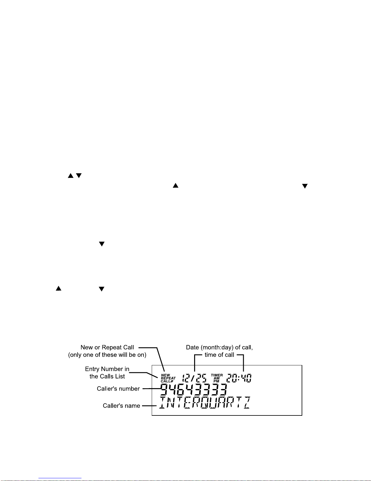
A typical call displayed from the Calls list is depicted in Figure 5.
FIGURE 5: DISPLAY OF A TYPICAL CALL FROM THE CALLS LIST
Page 28
24
When reviewing the Calls list, you may see the following details:
“OUT OF AREA” a caller’s network does not offer the Caller ID service or the call is from a n
oversea s caller or a payphone.
“PRIVATE” a caller has blocked his/her number from being tran smitted and displayed.
“LINE ERROR” the telephone ca nnot recognise the inf ormation contained with the Caller
ID message.
NEW - new calls have been received that have not previously been
reviewed in the Calls list
REPEAT - indicates multiple calls have been received from the same
caller in the current Calls list’s history; therefore please note that only
the most recent call from that caller’s number will be retained in the
Calls list.
CALL
- entry number in Calls list
Date in Month/Day format; shows current date or date of received call
when reviewing Calls list
For the clock readout and when reviewing the time that a call arrived in the
Calls list (displays only in 12 hour mode)
Hour:Minute format for the clock readout a nd when reviewing the time that
a call arrived in the Calls list (displays only in 12 hour mode)
Indicates, when reviewing the Calls list, that the call wa s a nswered on the
IQ335
Indicates, when reviewing the Calls list, that the call was NOT an swered on
the IQ335
Page 29

25
To store a caller’s details in a Dire ct Acce ss me mory from the Calls List
1. Press CALLS; the most recent incoming caller’s na me a n d number will be displayed
2. Scroll (press or ) to select the number you want to save into the Direct Access memory
3. Press STORE; the display will show “STORE”
4. Press a memory key; the display will show “ENTER NUMBER” below the telephone number
5. Press STORE to confirm. Move the Cursor (press or ) to edit the number before saving
6. The display will show the caller’s name; press ST ORE to confirm. Move the Cursor (press or ) to
edit the na me bef ore saving
7. The display will show “MEMORY STORED”.
To store a caller’s details in the Dire ctory me mory from the Calls List
1. Press CALLS; the most recent incoming caller’s name and number will be displayed
2. Scroll (press or ) to select the number you want to save into the Directory memory
3. Press STORE; the display will show “STORE”
4. Press DIRECTORY; and the display will show “ENTER NUMBER” below the telephone number
5. Press STORE to confirm. Move the cursor (press or ) to change the number bef ore saving
6. The display will show the caller’s name; move the cursor (press or ) to edit the name if nece ssary
7. Press STORE to confirm; the display will show “DIRECTORY STORED”.
To delete a Call from the Calls List or to delete the entire Calls List
1. Press CALLS and Scroll (press or ) to find the entry you wish to delete
2. To erase the displayed call, press CLEAR twice in rapid succession; the display will show “ERASED”
3. To erase the entire Calls list, press CLEAR twice in rapid succession and hold the key down on the
second depression; the display will show “HOLD TO CLR CALL”
4. T o prevent entire dire ctory erasure release the CLEAR key at this time bef ore 6 seconds has elapsed;
otherwise keep holding the key down and go to the next step
5. 6 seconds from step 3 the directory will be deleted and the display will show “CALL MEM CLEAR”.
Note: See MEMORY OPERATION section for more details of storing and dialing operations using
Direct Access and Direct memories.
Page 30

26
8. ADV ANCED NETWORK OPERATION
Where this telephone is used on an intelligent network such as Ea sycall, Customnet, Centel, Spe ctrum,
a PABX or any Centrex networks, the following information may be useful.
Message Waiting function in conjunction with T elstra’s Customnet, Home Me ssage s 101 service s
and MessageBank
The IQ335 has built-in compatibility with the above services. When the Me ssage Waiting sign al is received:
1. the CALLS indicator key will flash
2. the display will show the words “Message Waiting” in the n a me f ield
3. the display will show an envelope icon.
Manually Resetting the Message Waiting Prompts
The message waiting prompts as described above are normally controlled by the network to switch on
and of f a s needed. If at any stage the telephone is found to be incorrectly indicating a Message Waiting
condition, the erroneous indication can be cleared manually. To clear the MWI prompts; press CLEAR
twice.
“Talking Text” SMS Messages
The IQ335 is compatible with the “Talking Text” SMS service. To access messages, ple ase refer to the
guidelines issued by your service provider.
HOLDING AND TRANSFERRING CALLS
The RECALL key’s functionality is dependent on your system type, so please check your system’s
extension user guide to find out how to use the RECALL key. It is sometim es known as the Flash or
Facility key. The Installation section contains inf ormation regarding settings that can affect the RECALL
key’s compatibility with your system.
PAUSE FUNCTION WHEN DIALING OUT
Sometimes a pause is necessary either when dialing ordinary outgoing calls, accessing specialised
network features or perhaps when storing certain numbers in the memory. If you have determined that
a pause is required by your host system, or if you have already experienced dialing difficulties, pleas e
review the information below.
AUTOMATIC TRUNK ACCESS DIGIT INSERTION
When the telephone is used wherever a di aling prefix is required to make an external call (e.g. normally
0 is needed for an outside line), this prefix ca n be stored to ensure that it is automatically dialed whenever
an external number is di aled from the Calls list. This resolv es a problem found in Caller ID ca pable network
environments where the caller ID information delivered to the receiving telephone does not contain the
outside line prefix necessary to complete a call-ba ck to that caller.
Page 31

27
To setup, model IQ335 a cce pts a one or two digit T runk Acce ss Code as follows:
1. Press STORE
2. Enter the Trunk Access digit (exa mple, 0 for Customnet)
3. Press STORE
4. Press “ ”
After progra mming digit 0 in the above exa mple the unit will insert a 0 in front of a ny outgoing number that is
dialed from the Calls list (the list of incoming calls).
This setting remains set until the user cha nges it - removal of power sources or line connection will not
change the setting.
Automatic Pause Insertion
The above procedure will also insert a pause after the access code before dialing the actual number
that has been selected for call-back from the Calls list. The pause time can be pre-set (see below).
PAUSE TIME
Sometimes the standard Pause time of 1 Second may be inappropriate, such as when a shorter pause
is needed to slow down a code stored in memory so that the telephone does not dial too quickly for the
network.
EXAMPLE: A particular network typically needs a short pause in the Call Hold function code after
“Recall” is sent to line and before “ 74” is dialed. A pause time of 200mSec is required in that code
sequence. The required Call Hold code is Recall, Pause (insert multiple pause(s) here), ,74.
Solution: Change the Pause time from the factory default of 1 Sec to 100mSec, and then program the
memory with enough pauses inserted in the code to achieve the desired pause time.
FIRST change the pause time to 100mSec
1. Press STORE; the display will show “STORE”
2. Press , , STORE; the display will show “1-RECALL 2-PAUSE”
3. Press 2 to enter Pause Time Selection; the display will show “PAUSE 1 SEC” (the factory default Pause
time)
4. Press Scroll (the one above the DIAL key) Up or Down to select 100mS
5. Press STORE to confirm selection; the display will show “P AUSE ST ORED”.
THEN progra m the Call Hold function code with 200mSe c of Pause time (two 100mSec Pauses) a s f ollows:
1. Press STORE; display shows “STORE”
2. Press any memory key; the display shows “ENTER NUMBER”
3. Press RECALL, PAUSE (twice), , 74; the display shows “FPP 74”
4. Press STORE; the display shows “ENTER NAME”
5. Enter text “CALL HOLD” on the keypad
6. Press “STORE”; the display shows “MEMORY STORED”
7. T est for resulting pause time stored in that memory key for network compatibility by pressing that memory
key at the appropri ate ti me a nd observing the result.
Page 32

28
If two Pauses (i.e. 200mSec) do not produce a long enough post-Recall pause for the network switch, try
three pauses (300mSec) or four (400mSec) or more.
The Pause time setting remains set until the user cha nges it - removal of power sources or line conne ction
will not change the setting.
HOLDING AND TRANSFERRING CALLS
The method used for these functions is dependent on your system type, so you will need to check your
system’s extension user guide. The RECALL key is typically used to transfer calls and the Recall Timing
setting affects the Recall key’s ability to function correctly with your system (see below).
USING THE MEMORIES
Any combination of numbers, and , Pause, Recall and Handsfree commands c an be stored. You
may find it useful to store some of your favourite network facility commands in the telephone for fast,
convenient access to those facilities (e.g. Diversion, Call Forward, Call Back etc). Consult your system
user guide for the codes that you need to store. The Direct Access memories can be pre-programmed at
point of sale with network feature codes. For further information, ple ase refer to the “Memory Operation”
and “Memory Protection Switch” sections of this manual.
Speed Dialing
When storing a number, you ca n a dd a “Speed Dialing” command to the start of the number. This makes
dialing faster and easier. The “H” comma nd, entered by pre ssing the HANDSFREE/HEADSET preceding
the telephone number in the Memory Storage procedure, activate s the ha nds free function during dialing
so that you can make a handsfree call just by pressing the memory key once it is programmed.
Cascade Memory Dialing
The contents of more than one memory can be “cascaded” or added together during a call to create a
long dialing sequence by pressing the required memory keys in the desired order. This feature can be
used to store unusually long numbers, which may exceed the digit capacity of any individual memory.
Page 33

29
9. INSTALLATION
GENERAL SETTING-UP
1. Fit the coiled cord to the appropriate sockets in the handset and the telephone base - please do not
connect it to the headset socket at the rear
2. Fit the line cord to the line socket and to your telephone network outlet
3. Set the Ringer Volume and the Ringer Pitch controls
4. See following sections to complete the installation
5. If using a headset, connect it to the headset jack shown in Figure 2B.
LINE CONNECTION
This telephone is supplied with a line cord and plug compatible with both 8 pin modular and 6 pin
modular wall sockets , with the centre pair being used for all telephony functions. Other types of plugs
and cords are available on request.
LOCATION
The telephone should be pla ced on a des k, table or shel f where it is not likely to be pushed o ff. If the unit
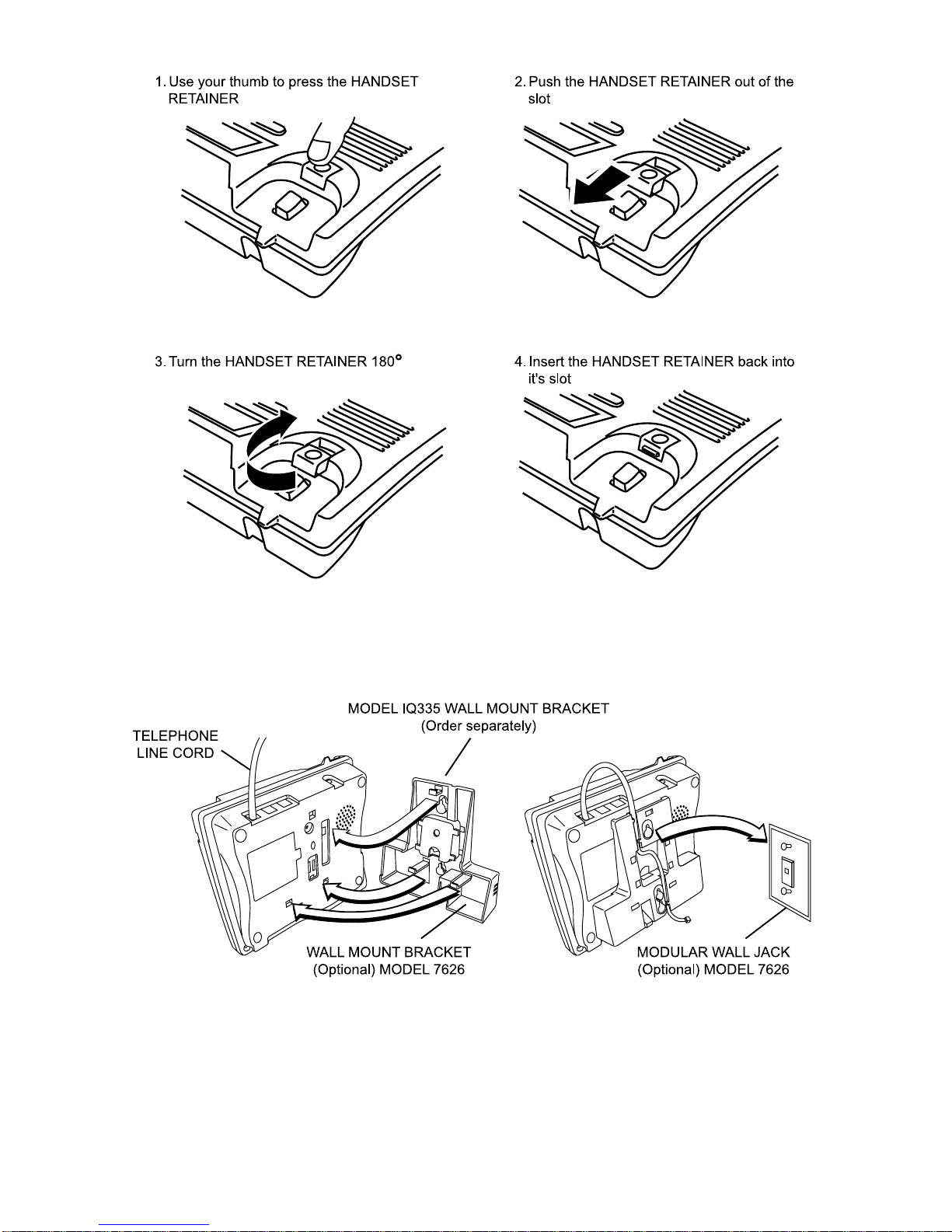
is to be wall-mounted, it should be seated securely on the IQ335 Wall Mount Bracket illustrated in
Figure 6B (please order separately). Avoid excessive heat, damp, dust, direct sunlight, vibration, and
other appliances or devices which may transmit or emit electrical or electromagnetic radio frequency
noise or signals (e.g. computers, welders, pagers).
W A LL MOUNTING
Use the IQ335 Wall Mount Bracket or Wall Mount Kit No.4 shown in Figure 6B (ple ase order separately).
1. To enable the Handset to be supported in the cradle, follow the procedure shown in Figure 6A to
reverse the Handset Retainer
2. Connect the link cord as shown
3. Fit the IQ335 wall mount bracket (optional, not supplied) to the underside of the telephone and
mount on the 7626 modular wall jack (see Figure 6B).
Page 34
30
FIGURE 6A : WALL MOUNTING
FIGURE 6B : IQ335 WALL MOUNT BRACKET. 7626 MODULAR WALL JACK AND LINK CORD
Note: The IQ335 Wall Mount Bracket, 7626 Modular Wall Jack and link cord illustrated in Figure 6B are
available from your authorised Interquartz dealer and can be ordered together as Wall Mount Kit
No.4.
Page 35

31
TECHNICAL ADJUSTMENTS - FOR CORRECT OPERATION
RECALL TIMING SELECTION
There are four different timings of 100, 200, 300 and 600 ms for selection. To select a Recall Timing
1. Press STORE; the display will show “STORE”
2. Press , then STORE; the display will show “1-RECALL 2-PAUSE”
3. Press digit 1 to enter Recall Ti ming selection; the display will show “RECALL 100MS” (it is the fa ctory
default recall time)
4. Press the Scroll key to select the desired timing. There are four different timings of 100, 200, 300 an d
600 ms for selection
5. Press STORE to confirm selection; the display will show “RECALL STORED”.
MESSAGE WAITING LIGHT COMPATIBILITY
No installation settings are required to enable the feature. If you have a PABX system, the red lense in
the top right hand corner will light when there is a message waiting. If the light does not function
correctly, your IQ335 may need an optional circuit to be added to make it compatible with your system.
If you have a Centrex system (e.g. Spectrum) the Calls key indicator and the “M ail” (envelope) icon will
flash and “MESSAGE WAITING” will be displayed. To retrieve your message, consult your voice mail
system user guide.
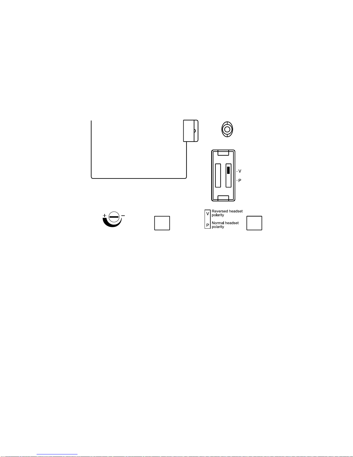
HEADSET MIC ADJUST CONTROL
This control allows many different headsets on the Australian market to function correctly with the
IQ335 telephone by adjusting the headset microphone sensitivity. The control is located on the underside
of the telephone (see Figure 7). The adjustment ca n be made by a small screwdriver or si milar imple ment
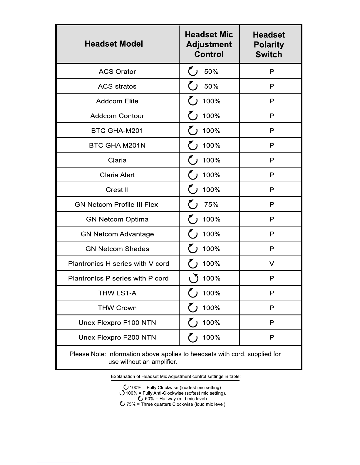
that will fit into the control slot. Please see Table 1 as a guide to the correct settings for some popular
Headsets.
To make a Headset mic level adjustment
With the Headset connected as per the instructions in this manual:
1. Put the Headset on and lift the Handset to your other ear and make an outgoing call
2. Pressing the HANDSFREE/HEADSET key , swap between Handset a nd Headset modes (the indicator
will illuminate when the headset is in use). Do this a few times while speaking to the other party by
repeatedly pressing the HANDSFREE/HEADSET key while holding a conversation
3. Use the other party’s help to decide if your voice level is the same on the headset in comparison to the
handset
4. If you sound too loud on the headset, reduce the microphone sensitivity (turn a nti-clockwise) so that your
voice level when using the headset matche s that of the handset. Clockwise rotation increa ses the He adset
Mic output level. Please see Table 1 a s a guide to the correct settings f or some popular hea dsets.
Page 36
32
HEADSET POLARITY SWITCH
Located on the underside of the telephone (see Figure 7), this switch provides compatibility with the two
commonly-used headset wiring sta ndards.
Position “V” suits Plantronics Vista cords a nd other hea dsets wired in the sa me conf iguration (also known
a s “reversed” wiring mode).
Position “P” suits Plantronics P cords and other headsets wired in the same conf iguration (also known as
“normal” wiring mode).
Plea se see Table 1 a s a guide to the correct settings f or most popular hea dsets.
HEADSET
MIC ADJUST
FIGURE 7: HEADSET MIC ADJUST CONTROL AND POLARITY SWITCH
Page 37
33
TABLE 1
Page 38

34
10. GENERAL CARE AND MAINTENANCE
This telephone is a precision electronic instrument. While in use and storage, care should be taken to
avoid rough handling, extreme temperature, and damp or dirty environments.
CLEANING
NEVER use aerosol sprays or other chemical agents or substances that leave a residue (furniture
polish for example).
Use a mild detergent and a damp, clean cloth when clea ning. Do not allow moisture to enter the telephone
interior - damage may result!
F AILURE TO OPERAT E AND SERVICE DIFFICUL TIES
If telephone service problems occur at any time, it is recommended that the installation procedure
described in this manual be re-checked.
If a fault occurs, try to determine if the fault is with the telephone, or with the network or system to which
the telephone is connected:
Disconnect the “suspect” telephone, and test the line with a substitute telephone. If the telephone
service then operates satisfactorily, the fault is in the “suspect” telephone. T est the “suspect” telephone
on a known good line. If the fault still occurs, the fault is in the “suspect” telephone.
Consult your Interquartz dealer for further advice if necessary.
Page 39

35
11. THUNDERSTORMS
The telephone, in common with household electrical a ppli ances, can be a source of electric a nd acoustic
shock during thunderstorms. The possibility of a telephone user experiencing a shock is minimal.
Nevertheless, customers should be aware of some simple precautions to follow during thunderstorms:
Use your telephone only for calls of the utmost urgency. Keep these calls brief. Whilst using your
telephone keep clear of electrical appliances and metal fixtures such as : stoves, air conditioners,
refrigerators, window frames and sinks.
Page 40

36
12. SERVICE
Please call 1800 6 IQTEL (1800 647 835) or email [email protected] from anywhere in
Australia.
13. WARRANTY: 3 YEARS PARTS & LABOUR
Interquartz (A’Asia) Pty Ltd warrants the original purchaser against failure, under normal usage and in
the environment a nd network for which it wa s de signed, resulting from defective materi al and work man ship
at time of manufacture for a period of THREE YEARS from the date of purchase. Interquartz reserves
the right to require proof of purchase a nd proof of date of purchase to determine validity of this warranty.
This warranty does not cover defects or damage due to normal wear and tear, negligence, accidents,
exposure to radiation, misuse, obsolescence, incompatibility, improper maintenance, lightning strikes
or unauthorised repairs or modifications a nd excludes freight or postage costs to/from your local authorised
service centre unless otherwise arra nged. Consequential loss not included. Notification of a ny defect must
be made within the warra nty period bef ore a warra nty re pair ca n be ef fected. This guara ntee is in a ddition
to all other W arranties or Guarantees expre ssed or implied by the T rade Practice s Act or other Commonwealth
or State laws and all other obligations a nd lia bilities on the part of Interquartz (A’Asia) Pty . Ltd.
Determination of W arranty Expiry
Every Interquartz IQ335 telephone carries a label that indicates the date of ma nufa cture. The text on that
label will follow the f ormat “YYWW” where “WW” indicates the week number (52 weeks per year) a nd “YY”
indicates the la st two digits of the year. For example, “0511” would signify that the telephone was made
during week 1 1 of 2005. The warra nty stated above commences three months after this date in lieu of proof
of purcha se that supports any other commence ment date.
Page 41

39
Manufactured by
International Quartz Limited
A Subsidiary of Chiaphua Industries Ltd.
©Copyright INTERNATIONAL QUAR TZ LTD. 2005
 Loading...