

Page 1
GENERAL PUMP A member of the Interpump Group
8
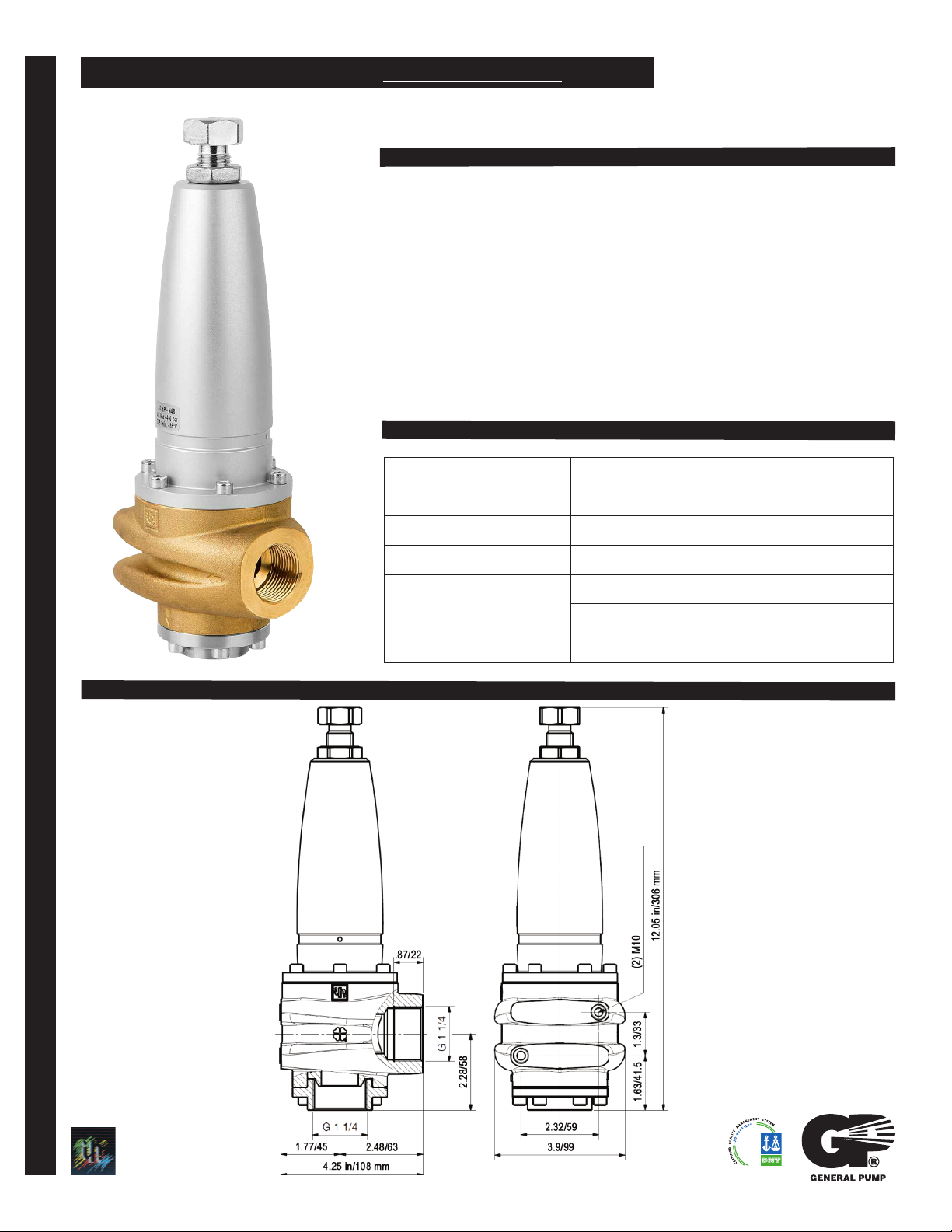
FEATURES
• Feature new, lighter design and hot water
capability
• Regulates the operating pressure of the
system by releasing excess volume through
the by-pass
• Protects the system from over pressurization
SPECIFICATIONS
Part Number R3LP/230
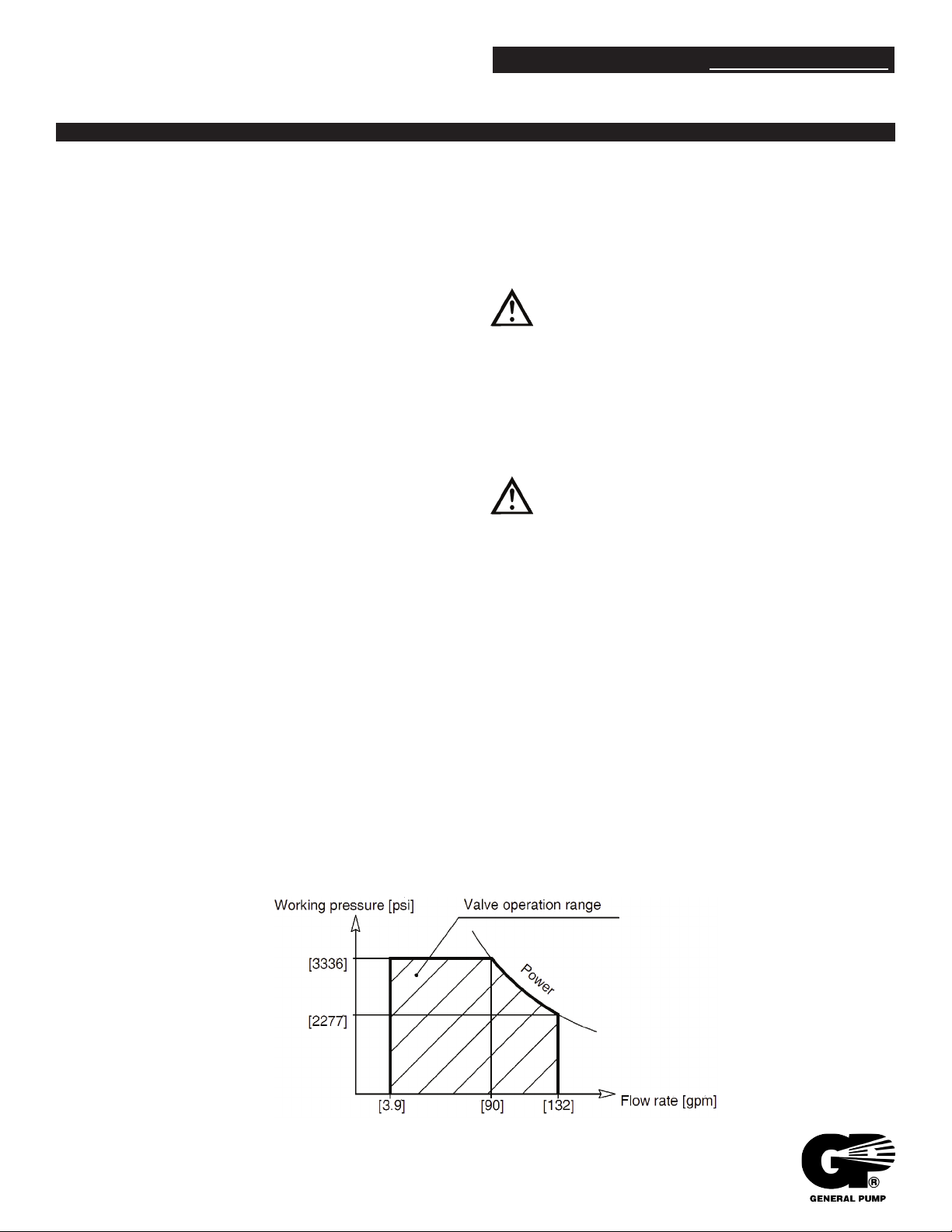
Maximum Pressure 3,335 PSI
R3LP/230
Pressure Regulating Valve
DIMENSIONS
Maximum Flow 132 GPM
Maximum Temperature
Port Sizes: Inlet
Bypass
Weight 13.2 lbs.
185oF
G 1-1/4”
G 1-1/4”
REGULATING & RELIEF VALVES REGULATING & RELIEF VALVES
Ref 300931 Rev. A
General Pump
is a member of
the Interpump
Group
08-13
Page 2
R3LP/230
Pressure Regulating Valve
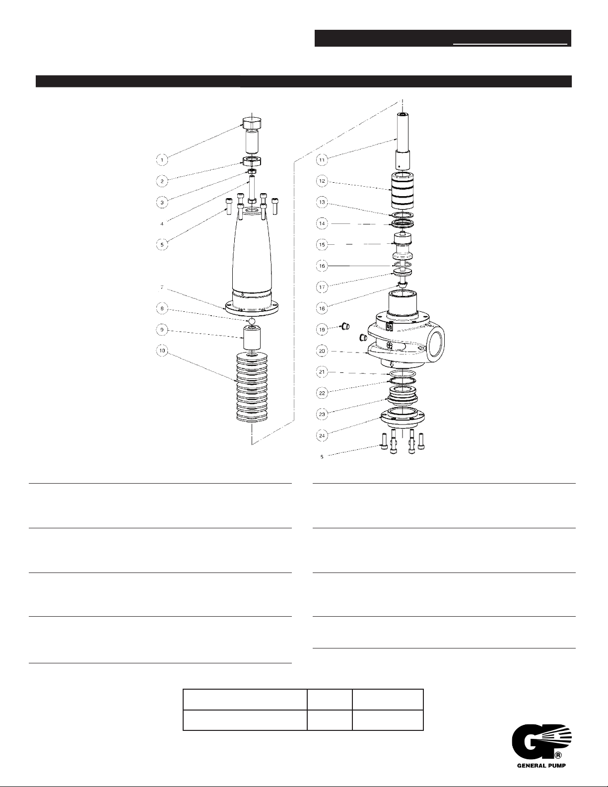
PARTS LIST
GENERAL PUMP A
member of the Interpump Group
Item Part Number Description Qty
1 F36011834 Regulating Screw, M20 1
2 F92264200 Bushing, M20-8 1
3 F92221600 Nut, M8x5x13 1
4 F99311500 Screw, M8x40 1
5 F99188400 Screw, M6x20 12
7 F36011761 Sleeve 1
8 F97483800 Ball, 13/32 1
9 F36011964 Spring Bushing 1
10 F94857400 Spring Disk, 50x18.3x2.5 14
11 F36012066 Spring Guide 1
12 F36012166 Piston, LP 1
13 F90517050 Anti-extrusing Ring, 28x36x1.5 1
REPAIR KIT
Item #s Included # of Pieces Kit #
13, 14, 16, 21, 22 1 F294
Item Part Number Description Qty
14 F90275200 Seal Ring, 28x36x6, LP 1
15 F36012366 Spacer, LP 1
16 F90360400 O-ring, 25.12x1.78 1
17 F36012507 Shutter, LP 1
18 F36006766 Screw, M8x88 1
19 F98195000 Plug, 8.5x11.5x7.5 2
20 F36011441 Body 1
21 F90387500 O-ring, 37.77x2.62 1
22 F90520500 Anti-extrusion Ring, 38.9x43x1.5 1
23 F36012766 Seat 1
24 F36012966 Flange for Seat 1
Ref 300931 Rev. A
08-13
Page 3
R3LP/230
Pressure Regulating Valve
INSTALLATION AND INSTRUCTIONS FOR USE
GENERAL PUMP A
The positions mentioned in the following instructions refer to
those shown in the parts list on page 2.
2.2 Connect the valve to the water system and follow these
steps:
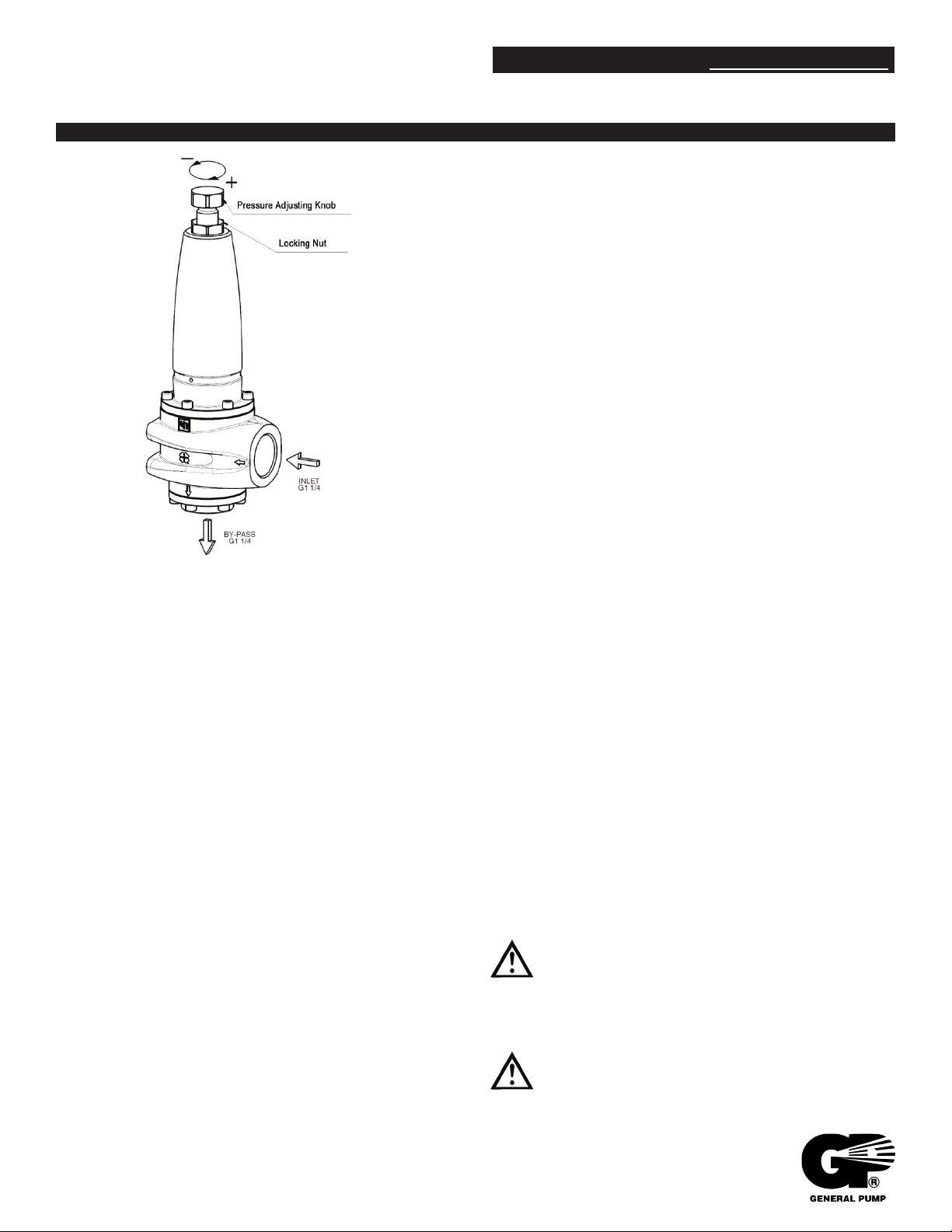
2.2.1 Loosen the nut (pos. 2).
2.2.2 Unscrew the nut (pos. 1) in order to completely release
the spring.
2.2.3 Open the gun or the water control device and start the
system. Make sure the air contained in it is fully ejected.
2.2.4 Keeping the gun or the water control device open, start
adjusting the pressure by screwing down the nut (pos. 1).
Alternate the adjusting operations with a few openings and
closings of the gun or of the control device. When the desired
pressure has been reached, open and close the gun/control device
a few times again in order to stabilize the various
components (seals, springs, etc.). Check the pressure valve
again and correct if necessary.
member of the Interpump Group
1. GENERAL INFORMATION
1.1 The R3LP/230 pressure regulator is a manually adjustable,
pressure operated devices, which, according to
its setting, limits the pumps/system pressure by conveying the
excess of water to the by-pass. Moreover, when the outlet flow is
blocked, this device totally releases the flow, thus keeping the
pump/system at the adjusted pressure.
1.2 Since the R3LP/230 valve is used in conjunction with a high
pressure water pump/system, which shall be called
hereafter only “system”, installation and use must be suited to the
type of system used and comply with the safety regulations in
force in the country where the valve is used.
1.3 Before using the valve, make sure that the system to valve
is used with is certified to comply with the relevant directives
and/or regulations.
1.4 Before installing and using the valve for the first time, we
suggest you check that it is undamaged and make sure that the
rated features correspond to the required ones. If this is not the
case, do not use the valve and contact the Customer Service
Department.
1.5 In order to install the valve correctly, follow the instructions for
the water inlet, outlet and by-pass connections, as stated in
this manual and/or the valve itself.
2. INSTRUCTIONS FOR PRESSURE SETTING
2.1 In order to obtain a correct adjustment and consequently a
proper functioning of the valve, always make sure that, when
working at the maximum pressure, the valve by-pass keeps
releasing a quantity of water equal to 5% of the total flow rate.
In case the flow rate at the by-pass is close to zero or exceeds
15% of the maximum flow rate, this could cause failure, early
wear and result in situations of danger.
2.2.5 Screw down the lower nut (pos. 2) up to contact with the
body.
2.2.6 In order to obtain working pressures lower than the
maximum set pressure, unscrew the nut (pos. 1).
3. WARNINGS
3.1 The installation and the setting of the maximum pressure must
be made by qualified staff only, who must have the required skills
to handle high pressure systems and be informed of the
operating and safety instructions contained in this manual.
3.2 The installer must provide the ultimate consumer with the
proper instructions for the correct use of the system the valve is
used in connection with.
3.3 Use soft and filtered water only. In case of salt water and/or of
water containing solid particles of a size exceeding 360µm, the
internal components of the valve will be subject to quick wear;
furthermore, this might compromise the correct functioning of the
valve. Addition agents can be used in the water, provided that
they are biodegradable and always complying with the regulations
in force in the country where the valve is used.
3.4 In the systems for hot water production, the
temperature of the liquid that comes into contact with
the valve must always be lower than the value stated
in this instruction manual and/or indicated on the valve
itself. Avoid the formation of steam or overheated
water.
IMPORTANT: When the temperature of the liquid is
close to the maximum value, the outside temperature
of the valve body is only slightly lower. Therefore,
take care in case of contact with the hot surface.
Ref 300931 Rev. A
08-13
Page 4
R3LP/450
Pressure Regulating Valve
INSTRUCTIONS FOR USE (CONT.)
GENERAL PUMP A
member of the Interpump Group
3.5 After use and/or before performing any operation on the
system or on the valve, release the pressure by using the
adjustment knob/screw and opening the gun or the control
device for a few seconds. The jet created by the residual
pressure must be directed downward in order to avoid damage
or injury.
3.6 For safety reasons, it is advisable to equip the high
pressure feeding line of the system also with a relief or safety
valve duly adjusted.
3.7 To connect the valve to the system it is referable to use
flexible hoses fitted in a way that they do not for 90
throttlings or siphons which could include harmful air bubbles.
The inside diameters of the hoses and fittings must be equal to
the correspondent inside diameters of the inlet, by-pass and
outlet threads of the valve. Moreover, it is necessary to correctly
choose the type of hose depending on the rated pressure and
flow rate; the hoses must always be used within their operation
limits as stated by the manufacturer and indicated on the hoses
themselves.
3.8 Tighten the fittings as follows:
In order to ensure the seal, fit a metal washer with a rubber ring
between the fittings, or use a proper sealant on the thread.
3.9 Always connect the valve by-pass fitting to a hose, in order to
avoid the excessive noise caused by the water outflow
through the by-pass without hose.
3.10 Before operating the system, it is advisable to start it for a
preliminary test run in order to check that the system is properly
installed.
0
elbows,
4.3 From time to time, it is necessary to check that the valve is
clean outside, and that there is no sign of leakage and/or
malfunctioning. If necessary, replace the involved parts. In case
of doubts, contact GP’s Customer Service Department.
4.4 Replace the valve parts with original spare parts only.
IMPORTANT: After maintenance, make sure that the
valve is re-assembled correctly and that the initial
conditions are restored. Comply with the torque wrench
setting values and set the pressure again as described
above.
4.5 The valve is entirely made of non-toxic and safe materials;
however, in case of disposal, we suggest you do not dispose of
it in the environment but take it to an authorized disposal center
or contact the Customer Service Department.
The valve shall not be tampered with for any reason
and/or used for any purpose other than the use it
has been designed for. In case of tampering, the
manufacturer disclaims all responsibility as to the
valve functioning and safety.
5. WARRANTY CONDITIONS
5.1 The period and conditions of warranty are specified in the
purchase contract.
5.2 Warranty is voided in case the valve is used for improper
purposes, used at higher performances than the rated ones,
repaired with non-original spare parts or if it turns out to be
damaged due to the non-compliance with the operating
instructions or to unauthorized tampering.
4. MAINTENANCE
4.1 Maintenance and repair must be carried out by qualified and
authorized staff only. Before any operation, make sure that the
valve and the system are shut down and made unusable.
4.2 A correct maintenance helps extend the working life and
grants a better performance of the valve.
GENERAL PUMP
Phone: 651.686.2199 • Fax: 800.535.1745 • e-mail: [email protected] • www.generalpump.com
1174 Northland Drive • Mendota Heights, MN 55120
Ref 300931 Rev. A
08-13
 Loading...