

Interpump TX 12.140.2, TX 12.100.2, TX 10.130.2, TX 12.100.4, TX 12.140.3 Operating Instructions Manual
...Page 1
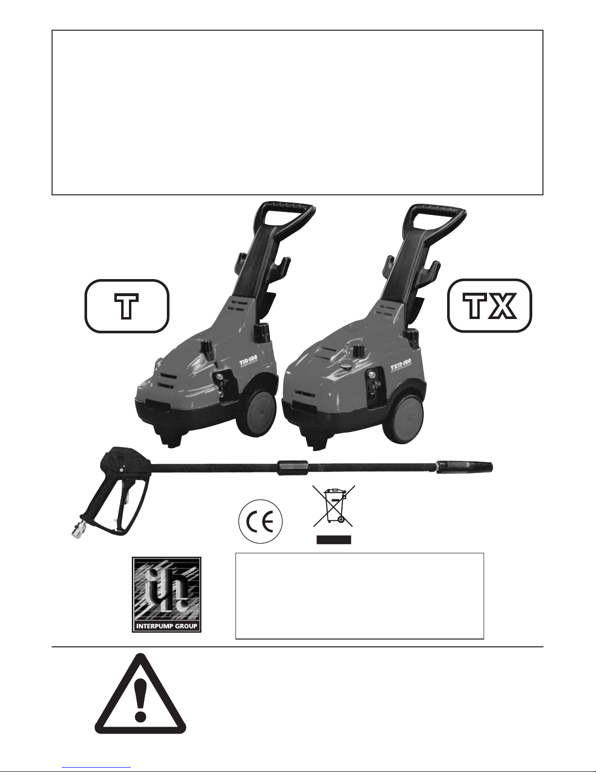
HIGH PRESSURE CLEANER
NETTOYEUR HAUTE PRESSION
HOCHDRUCKREINIGER
HIDROLIMPIADORA ALTA PRESIÓN
LAVADORA A ALTA PRESSÃO
ГИДРОМОЙКА ВЫСОКОГО ДАВЛЕНИЯ
IDROPULITRICE AD ALTA PRESSIONE
• OPERATING INSTRUCTIONS
• MODE D’EMPLOI
• BEDIENUNGSANLEITUNG
• INSTRUCCIONES PARA EL USO
• MANUAL DE INSTRUÇÕES
• ИНСТРУКЦИЯ ПО ЭКСПЛУАТАЦИИ
• LIBRETTO ISTRUZIONI
• DO NOT USE THE MACHINE WITHOUT FIRST READING THE OPERATING INSTRUCTIONS
• N’UTILISER L’APPAREIL QU’APRÈS AVOIR LU LE MANUEL D’INSTRUCTIONS
• GERAT ERST NACH LESEN DER BEDIENUNGSANLEITUNG VERWENDEN
• NO UTILISE EL APARATO SIN LEER ANTES LAS INSTRUCCIONES PARA SU USO
• NÃO USE A MÁQUINA SEM LER A MANUAL DE INSTRUÇÕES
••
НЕ ИСПОЛЬЗУЙТЕ УСТРОЙСТВО, НЕ ПРОЧИТАВ СНАЧАЛА ИНСТРУКЦИЮ ПО ЭКСПЛУАТАЦИИ
• NON USARE LA MACCHINA SENZA AVERE LETTO LE ISTRUZIONI PER L’USO
Page 2
3
ENGLISH............................................................................................ pag.
FRANÇAIS
....................................................................................... pag.
DEUTSCH
......................................................................................... pag.
ESPAÑOL
.......................................................................................... pag.
PORTUGUÉS
................................................................................ pag.
РУССКИЙ
....................................................................................................................................................................................
стр
..
ITALIANO
............................................................................................ pag.
6
25
44
63
82
101
120
INDEX
Models - Modèles - Modelle - Modelos -Модель - Modelli
TX 10.130.2
TX 10.130.4
TX 12.100.2
TX 12.100.4
TX 12.140.2
TX 12.140.3
TX 13.180.2
TX 13.180.3
TX 13.180.4
TX 17.130.4
TX 17.130.5
TX 951.6
TX 954.6
TX 956.6
TX 957.6
TX 961.6
TX 961.8
TX 13.180.5
TX 14.120.2
TX 14.120.3
TX 15.150.2
TX 15.150.3
TX 15.150.4
TX 15.150.5
TX 17.130.2
TX 17.130.3
Page 3
4
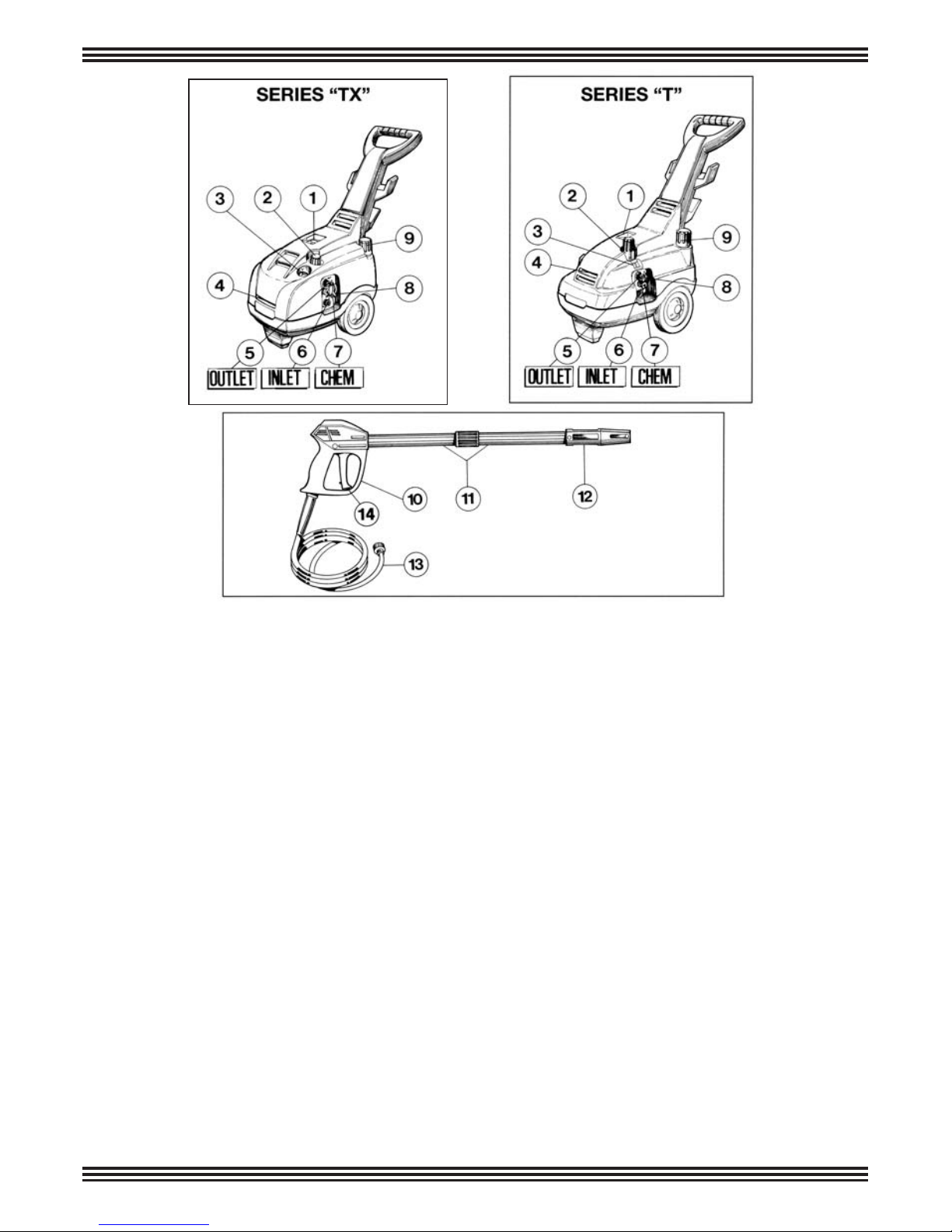
• CONTROL DEVICES
Before connecting the machine to the water and electrical supplies, it is necessary to know the function of the controls
on the machine. This must be done in accordance with the descriptions in the Instruction Manual, taking
reference to the relevant instructions and illustrations.
• DISPOSITIFS DE CONTRÔLE
Avant de brancher l’appareil sur les réseaux d’alimentation d’eau et d’électricité, il est nécessaire de bien connaître le
fonctionnement de ses dispositifs de contrôle. Effectuer cette opération en vous référant aux instructions données
dans ce manuel et aux indications et illustrations y relatives.
• BEDIENUNGS - UND KONTROLLVORRICHTUNGEN
Bevor Sie das Gerät mit Wasser - und Stromanschlüssen verbinden ist es notwending, daß Sie die Bedienungs-und
Kontrollvorrichtungen des Gerätes verstehen. Bitte lesen Sie die Beschreibungen und Illustrationen der
Bedienungsanleitung.
• DISPOSITIVOS DE PUESTA EN MARCHA Y CONTROL
Antes de conectar el equipo a las redes de alimentación de agua y electricidad, es necesario conocer sus dispositivos
de puesta en marcha y control. Efectuar estas operaciones siguiendo las indicaciones que figuran en el manual de
istrucciones así como de sus ilustraciones grafícas correspondientes.
• DISPOSITIVO DE COMANDO E CONTROLO
Antes da ligação às redes de alimentação hídrica e eléctrica, é necessário saber qual a função dos dispositivos de
comando e controlo da máquina. Efectuar esta operação conforme descrito no Manual de Instruções.
• УСТРОЙСТВА УПРАВЛЕНИЯ
Перед тем, как подсоединить изделие к источникам воды и электроэнергии, необходимо изучить его
устройства управления. Это необходимо сделать в соответствии с описаниями, содержащимися в настоящей
Инструкции по экплуатации, уделяя внимание соответствующим инструкциям и иллюстрациям.
• DISPOSITIVI DI COMANDO E CONTROLLO
Prima dell’allacciamento alla rete di alimentazione idrica ed elettrica è necessario conoscere la funzione dei dispositivi
di comando e controllo della macchina. Effettuare questa operazione seguendo quanto descritto nel Manuale Istruzioni
facendo riferimento alle indicazioni e illustrazioni relative.
Page 4

5
STANDARD EQUIPMENT
ON/OFF switch
Pressure adjusting knob
Pressure indicator
Oil level indicator
High pressure hose connection (OUTLET)
Inlet hose connection with water filter (INLET)
Outer chemical port
Chemical regulator (CHEM)
Built in tank cap
Automatic gun
“LANCE”
Rototek or Multireg 99
High pressure hose
Safety lock
EQUIPEMENT STANDARD
Interrupteur Marche/Arrêt
Bouton de régulation de la pression
Indicateur de pression
Indicateur de niveau d’huile
Raccord de tuyau haute pression (OUTLET)
Raccord d’alimentation eau et filtre (INLET)
Prise du réservoir extérieur détergent
Molette de dosage du détergent (CHEM)
Bouchon réservoir incorporé
Pistolet automatique
Lance a raccordement rapide “LANCE”
Rototek ou Multireg 99
Tuyau haute pression
Cran de sûreté
STANDARD AUSRÜSTUNG
EIN/AUS Schalter
Druckregel-Griff
Druckanzeiger
Ölschauglas
Hochdruck-Ausgang (OUTLET)
Wasser-Anschluß mit Filter (INLET)
Externe Chemiesaugdose
Chemiedosierung (CHEM)
Verschluß des eingebauten Chemietanks
Spritzpistole
Wechsel-Lanze “LANCE”
Rototek oder Multireg 99
Hochdruckschlauch
Sicherheitssperre
EQUIPO STANDARD
Interruptor
Mando de regulación de la presión
Mánometro
Mirilla nivel de aceite
Salida presión (OUTLET)
Entrada + Filtro agua (INLET)
Entrada aspiración deposito externo
Mando de regulación detergente (CHEM)
Tapón deposito interno
Pistola
Lanza
Rototek o Multireg 99
Tubo de alta presión
Seguro
EQUIPAMENTO STANDARD
Interruptor lig/des (ON/OFF)
Manipulo de ajuste de pressão
Indicador de pressão
Indicador de nivel de óleo
Conector de saida de alta pressão (OUTLET)
Entrada de agua com filtro (INLET)
Entrada de aspiração de detergente
Regulador de detergente (CHEM)
Tampa do depósito interno
Pistóla automática
Lança
Bico (ROTOTEK ou MULTIREG 99)
Lanço de tubo de alta pressão
Travão
СТАНДАРТНОЕ ОБОРУДОВАНИЕ
Выключатель
Регулятор давления
Манометр
Индикатор уровня масла
Выход (OUTLET)
Вход + Водяной фильтр
Вход всасывающего патрубка наружного бака
Регулировка моющего средства (CHEM)
Пробка внутреннего бака
Пистолет
Гидромонитор
Rototek или Multireg 99
Шланг высокого давления
Предохранитель
EQUIPAGGIAMENTO STANDARD
Interruttore
Comando di regolazione della pressione
Manometro
Spia livello olio
Uscita (OUTLET)
Entrata + Filtro acqua
Ingresso aspirazione serbatoio esterno
Regolazione detersivo (CHEM)
Tappo del serbatoio interno
Pistola
Lancia
Rototek o Multireg 99
Tubo alta pressione
Sicura
Page 5

66
TABLE OF CONTENTS
1 - Description of symbols on the high pressure cleaner....................................... 7
2 - Technical specifications of the T-TX series
high pressure cleaner................................................................................. 8-9-10
3 - Product use....................................................................................................... 11
3.1 • Designated use................................................................................... 11
4 - Preliminary operations...................................................................................... 11
4.1 • Unpacking........................................................................................... 11
4.2 • Identification label............................................................................... 12
5 - Installation......................................................................................................... 12
5.1 • Connection high pressure outlet......................................................... 13
5.2 • Connection to water supply................................................................ 13
5.3 • Connection to electric system............................................................ 14
5.3.1 • Cut-out switch (Only the United States).......................................... 15
5.4 • Use of extention cord......................................................................... 15
5.5 • Start-up............................................................................................... 16
6 - General warnings.............................................................................................. 17
7 - Chemical product use...................................................................................... 20
7.1 • Suction from internal tank ................................................................. 20
7.2 • Suction from external tank ................................................................ 20
8 - Use of "ROTOTEK" or "MULTIREG 99"........................................................... 21
9 - Precautions againt freezing, and instructions for storage................................... 21
10 - Maintenance...................................................................................................... 21
10.1 • Oil change......................................................................................... 22
10.2 • Inlet filter............................................................................................ 22
10.3 • Replacement of high pressure nozzle ............................................. 22
11 - Machine scrapping............................................................................................ 23
12 - Trouble shooting............................................................................................... 24
ENGLISH
Page 6
7
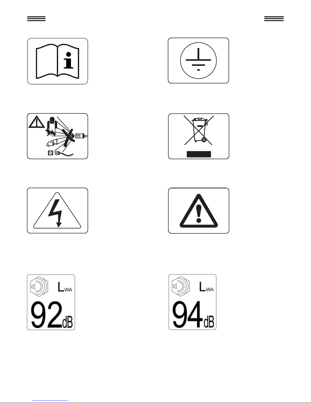
1 - DESCRIPTION OF SYMBOLS ON THE HIGH PRESSURE CLEANER
DDoo nnoott ddiirreecctt tthhee jjeett
aaggaaiinnsstt ppeerrssoonnss oorr
aanniimmaallss ppoowweerr oouutt--
lleettss oorr tthhee mmaacchhiinnee
iittsseellff..
WWaarrnniinngg!! RRiissk
k ooff
eelleeccttrrooccuuttiioonn
GGrroouunnddiinngg
SSppeecciiaall wwaassttee.. DDoo
nnoott ddiissppoossee ooff tthhiiss
pprroodduucctt iinn nnoorrmmaall
hhoouusseehhoolldd ggaarrbbaag
gee
WWaarrnniinngg ssiiggnn
RReeaadd tthhee iinnssttrruuccttiioonn
mmaannuuaall bbeeffoorree uussee..
GGaarraanntteedd ssoouunndd
ppoowweerr lleevveell..
TT SSEERRIIEESS
TTXX SSEERRIIEESS
GGaarraanntteedd ssoouunndd
ppoowweerr lleevveell..
Page 7
8
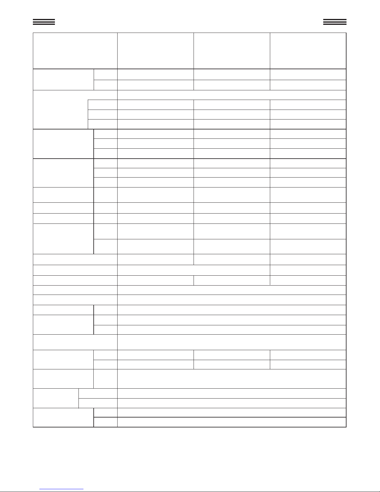
2 - T SERIES HIGH PRESSURE CLEANERS TECHNICAL SPECIFICATIONS
MODEL
Voltage
Amps
V
A
Capacitor
Motor protection
Isolating class insulation
Motor protection grade
°C
m/sec
2
Fixed nozzle A(8) than 2,5 - Rotating nozzle A(8) than 2,5
Max. water inlet
temp
°F
m
Max suction depth
ft
High pressure hose
Steel reinforced rubber - Internal diameter 1/4”
Working pressure max 150 bar - 15 MPa - 2175 P.S.I.
Mass
Dimensions
mm
inches
Noise level
*
Lance vibration
*
V
A
P.S.I.
Overpressure
peak limit
Recoil thrust of jet
N
Absorbed motor
power
kW
Cycle
Hz
l/min.
Flow rate
G.P.M.
USA
E.W. bar / MPa / P.S.I.: specific jet pressure in bar / MPa / P.S.I.
Equivalent
washing impact
with rotating
nozzle jet
E.W. MPa
E.W. P.S.I.
Working pressure
MPa
E.W. bar
bar
P.S.I.
MPa
bar
MPa 1 - bar 10 - P.S.I. 145
Max inlet pressure
*
(Reference Standard EN60335-2-79).
dry
(max.)
8 m
26 ft
T
8.90.2
SINGLE PHASE
T
10.100.2
10.100.4
SINGLE PHASE
T
11.120.2
11.120.3
TRIPLE PHASE
2.1
8
2.6
10
2.9
11
16
17
21
160
170 210
2320
2465 3045
90
100 120
9
10
12
1305
1450
1740
120
130 150
12
13 15
1740
1886
2175
< 20
< 27
< 32
2,2
2,65 2,9
50
50
50
230-1~
10,5
230-1~
12
230-3~
8,9
240-1~
9,5
50µF
–
Thermal
F
F
B
IPX5
Lp dB(A) 76 (uncertainly 1,5) - Lw dB(A) 92
60
140
11
1
3,3
3,3 3,3
Kg 34 - Ibs 75
Kg 43,5 - Ibs 96
860x400x875 (h)
33,8x15,7x34,4 (h)
50µF
240-1~
11,5
400-3~
5,2
–
Page 8
9
MODEL
Voltage
Amps
V
A
Capacitor
Motor protection
Isolating class insulation
Motor protection grade
°C
m/sec
2
Fixed nozzle A(8) than 2,5 - Rotating nozzle A(8) 7 (uncertainly 1)
Max. water inlet
temp
°F
m
Max suction depth
ft
High pressure hose
Steel reinforced rubber - Internal diameter 5/16”
Working pressure max 200 bar - 20 MPa - 2900 P.S.I.
Mass
Dimensions
mm
inches
Noise level
*
Lance vibration
*
V
A
P.S.I.
Overpressure
peak limit
Recoil thrust of jet
N
Absorbed motor
power
kW
Cycle
Hz
l/min.
Flow rate
G.P.M.
USA
E.W. bar / MPa / P.S.I.: specific jet pressure in bar / MPa / P.S.I.
Equivalent
washing impact
with rotating
nozzle jet
E.W. MPa
E.W. P.S.I.
Working pressure
MPa
E.W. bar
bar
P.S.I.
MPa
bar
MPa 1 - bar 10 - P.S.I. 145
Max inlet pressure
*
(Reference Standard EN60335-2-79).
dry
(max.)
8 m
26 ft
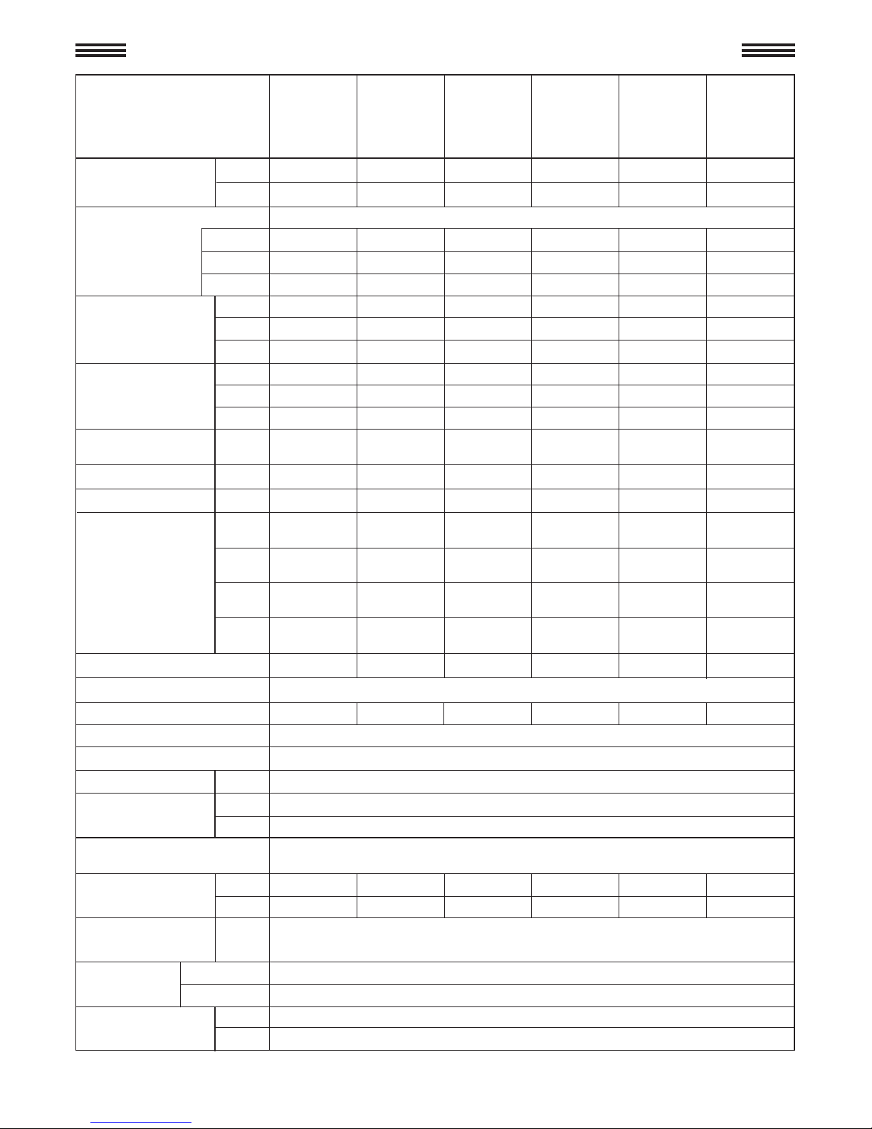
TX
15.150.2
15.150.3
15.150.4
15.150.5
TRIPLE PHASE
TX
10.130.2
10.130.4
SINGLE PHASE
TX
12.100.2
12.100.4
SINGLE PHASE
TX
12.140.2
12.140.3
TRIPLE PHASE
TX
13.180.2
13.180.3
13.180.4
13.180.5
TRIPLE PHASE
TX
14.120.2
14.120.3
TRIPLE PHASE
V
A
V
A
2.5
9,5
3.2
12
3.2
12
3.4
13
3.7
14
4
15
23
17 24,5 31 21 26
230
170 245
310
210
260
3336
2465 3553
4496
3045
3771
130
100 140 180 120 150
13
10 14 18 12 15
1886
1450
2030
2610
1740
2175
160
130 170
210
150
180
16
13 17
21
15
18
2320
1886 2465
3045
2175 2610
< 29
< 32
< 40
< 47 < 41
< 49
3,2
3,2 3,8
5
3,8 5
50
50 50
50
50 50
230-1~
14,7
230-1~
14,7
230-3~
12,5
230-3~
15,8
230-3~
12,5
230-3~
15,8
240-1~
13,6
240-1~
13,6
400-3~
7,2
400-3~
9,2
400-3~
7,2
400-3~
9,2
240-3~
14,5
415-3~
8,5
2x40µF 2x40µF
––––
Thermal
FFFF
F
F
IPX5
Lp dB(A) 80 (uncertainly 1,5) - Lw dB(A) 94
60
140
33
3
1
9,8
9,8 9,8
3,3
31
9,8 3,3
Kg 44,5 - Ibs 98,1
Kg 54 - Ibs 119
860x400x875 (h)
33,8x15,7x34,4 (h)
240-3~
14,5
415-3~
8,5
2 - TX SERIES HIGH PRESSURE CLEANERS TECHNICAL SPECIFICATIONS
Page 9
10
MODEL
Voltage
Amps
V
A
Capacitor
Motor protection
Isolating class insulation
Motor protection grade
°C
m/sec
2
Fixed nozzle A(8) than 2,5 - Rotating nozzle A(8) 7 (uncertainly 1)
Max. water inlet
temp
°F
m
Max suction depth
ft
High pressure hose
Steel reinforced rubber - Internal diameter 5/16”
Working pressure max 200 bar - 20 MPa - 2900 P.S.I.
Mass
Dimensions
mm
inches
Noise level
*
Lance vibration
*
V
A
P.S.I.
Overpressure
peak limit
Recoil thrust of jet
N
Absorbed motor
power
kW
Cycle
Hz
l/min.
Flow rate
G.P.M.
USA
E.W. bar / MPa / P.S.I.: specific jet pressure in bar / MPa / P.S.I.
Equivalent
washing impact
with rotating
nozzle jet
E.W. MPa
E.W. P.S.I.
Working pressure
MPa
E.W. bar
bar
P.S.I.
MPa
bar
MPa 1 - bar 10 - P.S.I. 145
Max inlet pressure
*
(Reference Standard EN60335-2-79).
dry
(max.)
8 m
26 ft
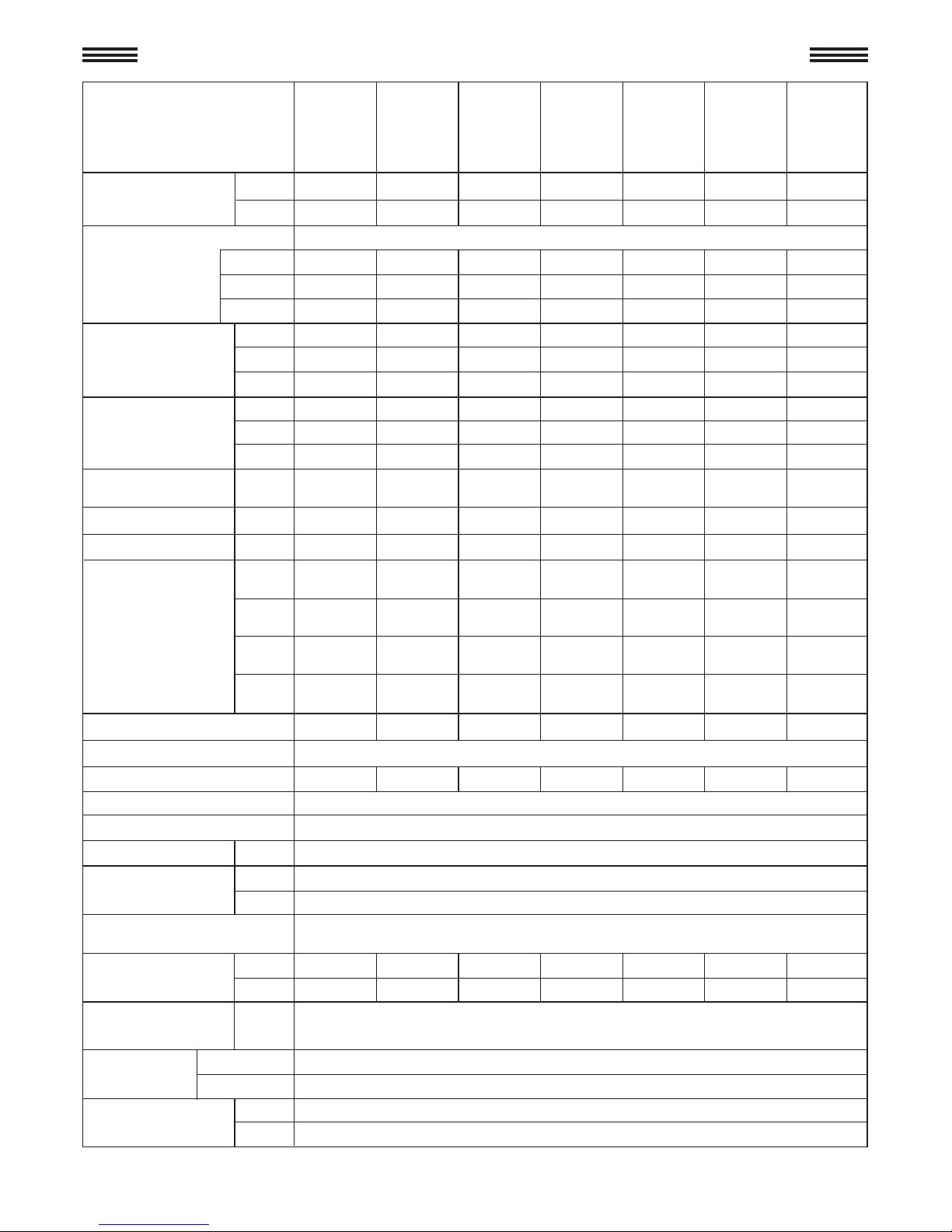
TX
17.130.2
17.130.3
17.130.4
17.130.5
TRIPLE PHASE
TX
951.6
SINGLE PHASE
TX
954.6
SINGLE PHASE
V
A
V
A
4.5
17
3
11,5
3.6
13,6
23
17 16
230
170 160
3336
2465 2320
130
103 90
13
10,3
9
1886
1494
1305
160
133 120
16
13,3 12
2320
1929 1740
< 51
< 31
< 35
5
3,2 3,2
50
60 60
230-3~
15,8
220-1~
15,5
220-1~
15,5
400-3~
9,2
240-3~
14,5
415-3~
8,5
– 2x40µF
2x40µF
Thermal
FBB
IPX5
Lp dB(A) 80 (uncertainly 1,5) - Lw dB(A) 94
60
140
11
1
3,3
3,3 3,3
Kg 44,5 - Ibs 98,1
Kg 54 - Ibs 119
860x400x875 (h)
33,8x15,7x34,4 (h)
TX
956.6
TRIPLE PHASE
3.4
13
25
250
3626
145
14,5
2103
175
17,5
2538
< 41
4,6
60
220-3~
16,5
–
F
3
9,8
TX
957.6
SINGLE PHASE
4.2
15,9
14,5
145
2103
76
7,6
1102
106
10,6
1537
< 37
3,2
60
220-1~
15,5
2x40µF
B
1
3,3
TX
961.6
961.8
TRIPLE PHASE
4
15
26
260
3771
150
15
2175
180
18
2610
< 49
5
60
220-3~
15,8
380-3~
9,2
–
F
1
3,3
TX
955.6
TRIPLE PHASE
3.4
13
18,7
187
2700
11
110
1600
140
14
2030
< 37
3,4
60
200-3~
12,0
–
F
1
3,3
2 - TX SERIES HIGH PRESSURE CLEANERS TECHNICAL SPECIFICATIONS
Page 10

11
WE CONGRATULATE YOU on your choice that shows your level of technical knowledge and
love of beautiful objects.
In fact, you have purchased a highly technological machine produced by the world's
largest manufacturer of high pressure cleaner pumps.
This machine is so useful and versatile that you will use it for many years.
THIS BOOKLET IS AN INTEGRAL PART OF YOUR MACHINE AND SHOULD BE
CAREFULLY READ BEFORE PROCEEDING WITH INSTALLATION, START-UP AND
USE.
This booklet contains important safety information and instructions for use and maintenance
of the high pressure cleaners series T-TX and should be kept in a safe place.
3. PRODUCT USE
3.1 DESIGNATED USE
THE DESIGNATED USE OF THIS PRODUCT MUST BE RESPECTED. ANY OTHER USE
OF THIS PRODUCT IS CONSIDERED INCORRECT.
THE MANUFACTURER IS NOT RESPONSABLE FOR DAMAGE CAUSED TO THE
MACHINE WHEN USED INCORRECTLY.
THE MACHINE MUST NOT BE TAMPERED WITH FOR ANY REASON. IN SUCH CASES
THE MANUFACTURER IS NOT RESPONSIBLE FOR THE MALFUNCTIONING
OR SAFETY OF THE MACHINE.
IT IS FORBIDDEN TO STORE OR USE THE UNIT IN ENVIRONMENTS WITH
POTENTIALLY EXPLOSIVE ATMOSPHERE
4. PRELIMINARY OPERATIONS
4.1 UNPACKING
Unpack and make sure that the machine is complete and undamaged.
If the machine appears damaged in any way, do not use the machine and consult our dealer.
For shipping reasons some parts may be included separately. In this case assemble parts as
indicated in this booklet.
Keep all packaging materials (bags, boxes, tape) out of reach of children.
The machine is exclusively designed for washing, by way of a pressurized water jet, objects,
things or any surface suitable for cleaning by a pressurized water jet with the possibility of
adding liquid detergent.
ATTENTION: this appliance was designed for use of detergents recommended by the manufacturer. The use of other chemical products may jeopardize the safety of the appliance itself.
The liquid detergent additives must be chosen in consideration of the chemical compatibility
with the components of the pump and of the surface to be cleaned.
IMPORTANT: use only detergents that are biodegradable, and in any case complying with the
regulations applicable in the country where they are used.
Page 11
12
A
B
Before using the machine, make sure that it is provided with the
identification Label. In case the Identification Label is missing,
do not use the machine and consult your dealer immediately.
The Identification Label with the technical specifications is fixed
to the motor.
Check that the mains voltage is the same as shown on the identification label.
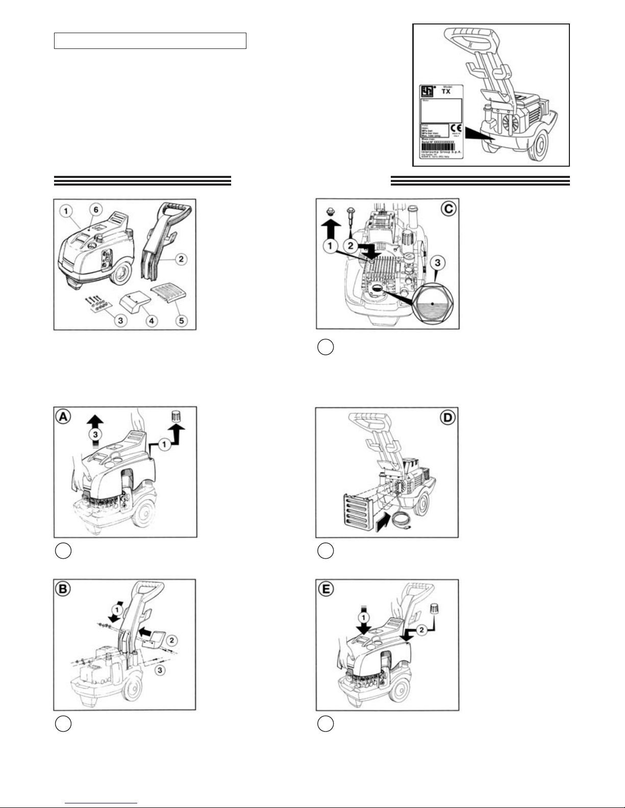
4.2 - IDENTIFICATION LABEL
5 - INSTALLATION
Body of the unit
Handle
Kit of screws + washers + nuts
Hose hanger
Fan grid
Cover fixing knob
Remove the cap of the chemical tank
Unscrew cover fixing knob
Remove the cover
C
Replace the red plug (Fig. 1) with the black and yellow
dipstick (Fig. 2) and check that the oil in the sigth
glass is at half-way level (Fig. 3).
D
Insert fan grid into its holes and push firmly until it is
fully locked.
E
Replace the cover.
Reinsert the chemical tank cap.
Lock cover fixing knob.
Insert the handle in its guides.
Fix the handle and hose hanger by using screws,
nuts and washers supplied.
Fix the bottom of the handle by using screws, nuts
and washers supplied.
Page 12
13
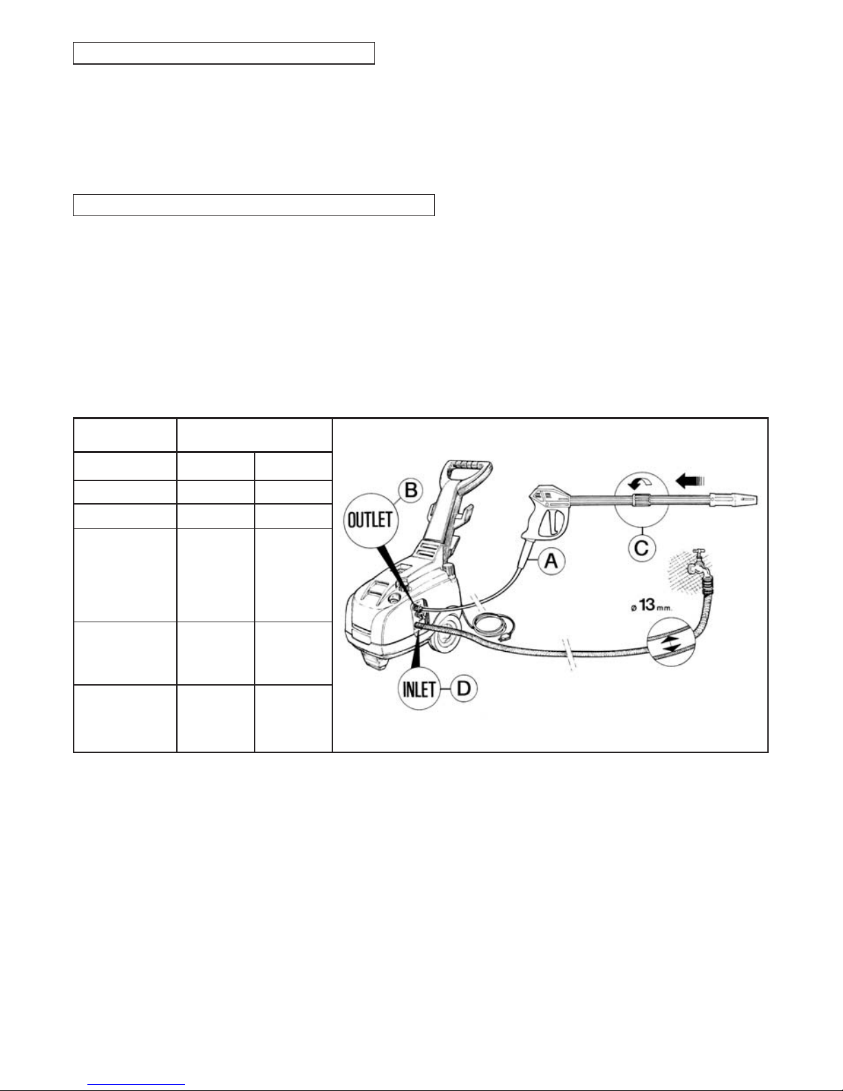
5.1 HIGH PRESSURE CONNECTION
1 - Connect one end of the high pressure hose to the automatic gun (A) and the other end to
the OUTLET connection on the machine. Tighten firmly (B).
2 - Complete the assembly by coupling the extension to the gun/lance and tighten firmly (C).
5.2 - CONNECTION TO THE WATER SUPPLY
1- The maximum temperature of the inlet water must not exceed 60°C (140°F).
2- Connect the water supply to the INLET (D) port by means of a reinforced hose (min.15
bar/1,5 MPa/200 psi) with the internal diameter not less than 13mm (1/2”)
3- Since the water flow decreases according to the length of the hose, make sure that the quantity of water supplied to the machine is not less than the quantities indicated in the chart below.
4- The pressure of the inlet water must not exceed 10 bar, 1 MPa, 145 psi.
ATTENTION: The water supply which enters into the washer is not drinkable.
IMPORTANT
The water supplied to the machine must be clean. Running the unit without water, or with water
which is dirty, contains grit or corrosive liquids, causes serious damage to the machine.
If the user wishes to power the washer by means of free suction, simply emerge the end of the
supply tube in the water to be suctioned. The maximum suction depth considered as the distance in height between the water surface and the pump varies between 1 m. and 3 m. (see
technical specifications table).
MODEL L/min.
G.P.M. USA
T-TX SERIES
FLOW RATE OF
WATER SUPPLY
T 10-100
T 11-120
TX 10-130
TX 12-100
TX 12-140
TX 951
TX 14-120
TX 13-180
TX 956
TX 954
TX 15-150
TX 17-130
TX 957
TX 961
15
17
20
4
4.5
5.3
T 8-90
11
2.9
TX 955.6
13
3.4
Page 13

14
5.3 - CONNECTION TO ELECTRICAL SYSTEM
1 - Check that the voltage of the electrical system (mains) is the same as indicated on the ID
label of the machine.
2 - Check that the plug complies with local safety regulations, and that it is provided with
ground connection (earth).
3 - Ensure that the outlet is protected by a "cut-out" (differential magnetic-thermal switch with
sensitivity of less than 30mA per 30ms) or that a device is present which can test the earthing
circuit.
4 - Do not connect other appliances contemporaneously to the same power outlet.
5 - Insert the plug only after checking that the machine switch is in the OFF position.
The T-TX cleaners series are supplied without electric plug.
The assembly of the electrical plug must be done in conformity with IEC rule n. 60364-1 and
must be effected by qualified personnel, respecting following prescriptions:
1- Use a plug which complies with the local safety regulations and which must necessarily be
grounded.
2- Make sure that the cord/plug connection is perfectly sealed and water-tight.
3- Use plugs that conform to the indications on the ID Tag.
4- Unroll the cord completely to avoid overheating.
5- Do not crush on the power cord.
6- Do not use the high pressure cleaner if the electric cable is damaged.
7- If the power cord is damaged, its replacement can be effected only by the technical service
personnel or by a qualified technician.
In case of direct connection without plug, the connection to the electric network must be in
compliance with the standard IEC 60364-1 and must be made by a qualified installer. If a plug
connector is used as a sectioning device, this must be in an easily accessible position.
In the threephase models the three power leads of the power cord can be connected to any of
the three phases from the power network. The fourth, green-yellow lead must be connected to
the ground pin.
The washer must only be connected to a power mains with a maximum network impedance of
Zmax=0.3 Ω.
WARNING: IN CASE OF POWER FAILURE DURING USE OF THIS MACHINE, TURN
THE MACHINE POWER SWITCH TO THE OFF POSITION FOR SAFETY REASONS.
Page 14

15
5.4 - USE OF CORDS
If an extension cord is used, make sure that plug and receptacle are of a water-tight type. In
any case they must be raised from the ground in order to avoid possible contact with water.
Use only extension cables with the same number of conductors as those of the machine cable,
including the earthing cable, and with a suitable plug/socket for the cable used.
Only use extension cords for outdoor use. Said type of cable is marked "Suitable for outdoor
use." Store inside when not in use.
Do not use damaged extension cords. Cables should not be located near sources of heat or
sharp edges. Always disconnect the plug from the socket before removing the extension cord
from the product. Do not pull the cable to pull the plug out of the outlet. Do not touch the plug
or connections with wet hands.
WARNING
USE OF INADEQUATE
EXTENSION CORDS
MAY CAUSE SAFETY
HAZARDS
SELECTION TABLE
Voltage
220÷240
220÷240
380÷415
Extension
cord length
Cord section
mm
2
Up to 20 m
From 20 to 50 m
Up to 50 m
2,5
4
2,5
5.3.1 - CUT-OUT SWITCH (Only the United States)
This UL version high-pressure washer is equipped with a cut-out switch contained in the power
cable plug.
Said equipment provides extra protection against the risk of electric shock.
When replacing the plug or cable, use the same components including the cut-out device.
Page 15
16
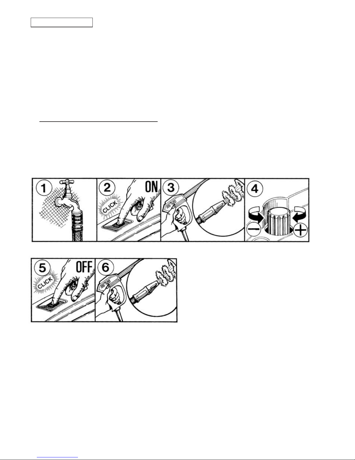
5.5 - START-UP
- Before starting up and using the machine, make sure that it is positioned on the ground or
leaning against a stable support and that the resting surface is level or with a minimum slope.
- It is ESSENTIAL to ensure that the suction filter is clean before use. (see maintenance chapter – 10.2 suction).
1- Open water supply
2- Push ON button
3 - Open the gun with nozzle end up and keep in open position to allow air to escape from the
hose.
4 - Regulate water pressure by rotating the regulator knob..
You are ready to work!!!
5 - At the end of working session turn the machine switch to the OFF position.
6 - Open the gun to release remaining pressure from the hose.
Page 16
17
6 - GENERAL WARNINGS
High pressure cleaners can be used neither
by children nor by non authorized persons.
Children must be supervised to prevent them
from playing with the machine.
Keep this machine out of reach of children
at all times.
This equipment was not designed to be used
by persons with reduced physical, sensorial or
mental capabilities, or with limited experience
or knowledge, unless a person responsible for
their safety provides them with supervision or
the instructions for the use of the equipment.
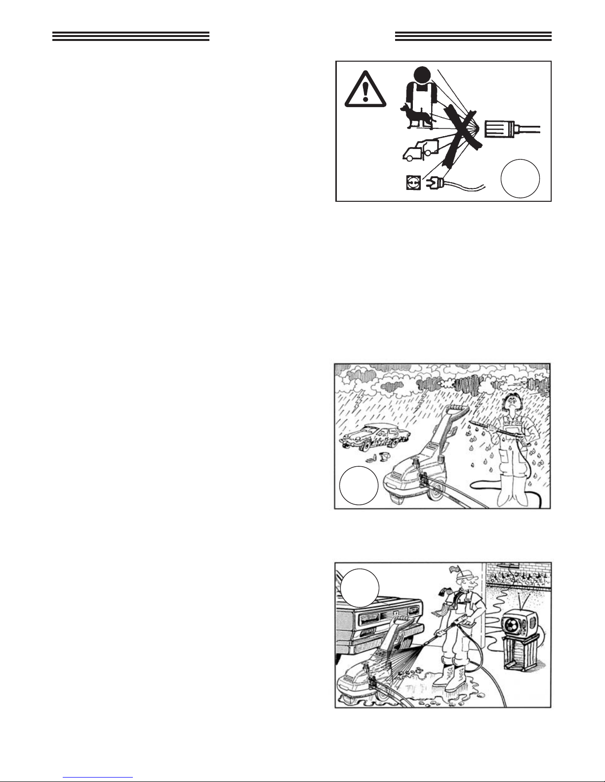
Only operate the machine in safety conditions, avoiding any potentially dangerous
situation for the user and others. The machine
operator should:
• Avoid to operate the machine on unbalanced
surfaces;
• Remember that the high pressure water jet
causes a recoil effect on the pistol. The recoil
values are indicated in the technical specifications table;
• Use protective clothing.
• Wear protective goggles and rubber slipproof boots
• Avoid dispersing substances that are polluting, toxic or harmful in any way.
ATTENTION: Risk of explosion. Do not spray
flammable liquids.
The high pressure water jet may be dangerous if used incorrectly. Never direct the jet at persons and/or animals, electrical appliances or the machine itself. Do not use the machine when
persons and/or animal are within the range of its high pressure jet.
Do not direct the jet against yourself or other persons to clean clothes or shoes.
NO
NO
NO
Page 17
18
This machine has been built in conformity
with current safety regulations. Use of electric
appliances requires the observations of a few
simple rules:
Do not touch electric parts when the machine
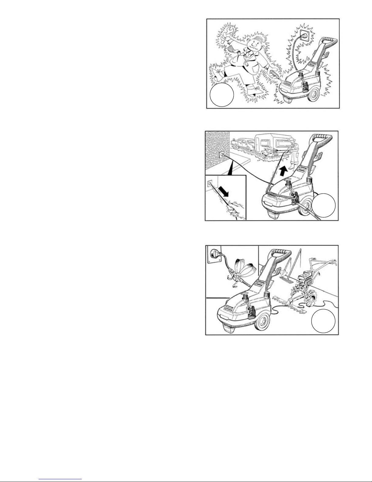
is on.
Inspection, maintenance and repairs should be
carried out by qualified personnel. In any case
unplug the machine before performing any of
the above operations.
Do not pull the cord to disconnect the power
supply and do not pull on the hose to move the
machine.
ATTENTION: high pressure flexible hoses,
high pressure connectors, safety devices,
electrical connections and spray guns are
important for the safety of the device.
Do not start the unit if the power cord is
damaged. Apply to qualified personnel for its
replacement. Replacement cords should have
the same technical specifications as the original cord. Do not carry out repairs on the electrical cord and avoid cord damage.
Do not start the unit if the high pressure hose, connectors and the gun are damaged. By
replacement make sure that the new components have at least the same rating as the original
components.The technical specifications of the hose should be printed on the hose itself (max
pressure, production date, manufacturer).
NO
NO
NO
Page 18
19
The unit is equipped with a current-thermal overload protector which switches and electrically
disconnects the motor in case of overheating.
If this should happen, please refer to the "Trouble
Shooting" section in this manual.
Avoid covering the machine during use and
use the machine in a well ventilated area.
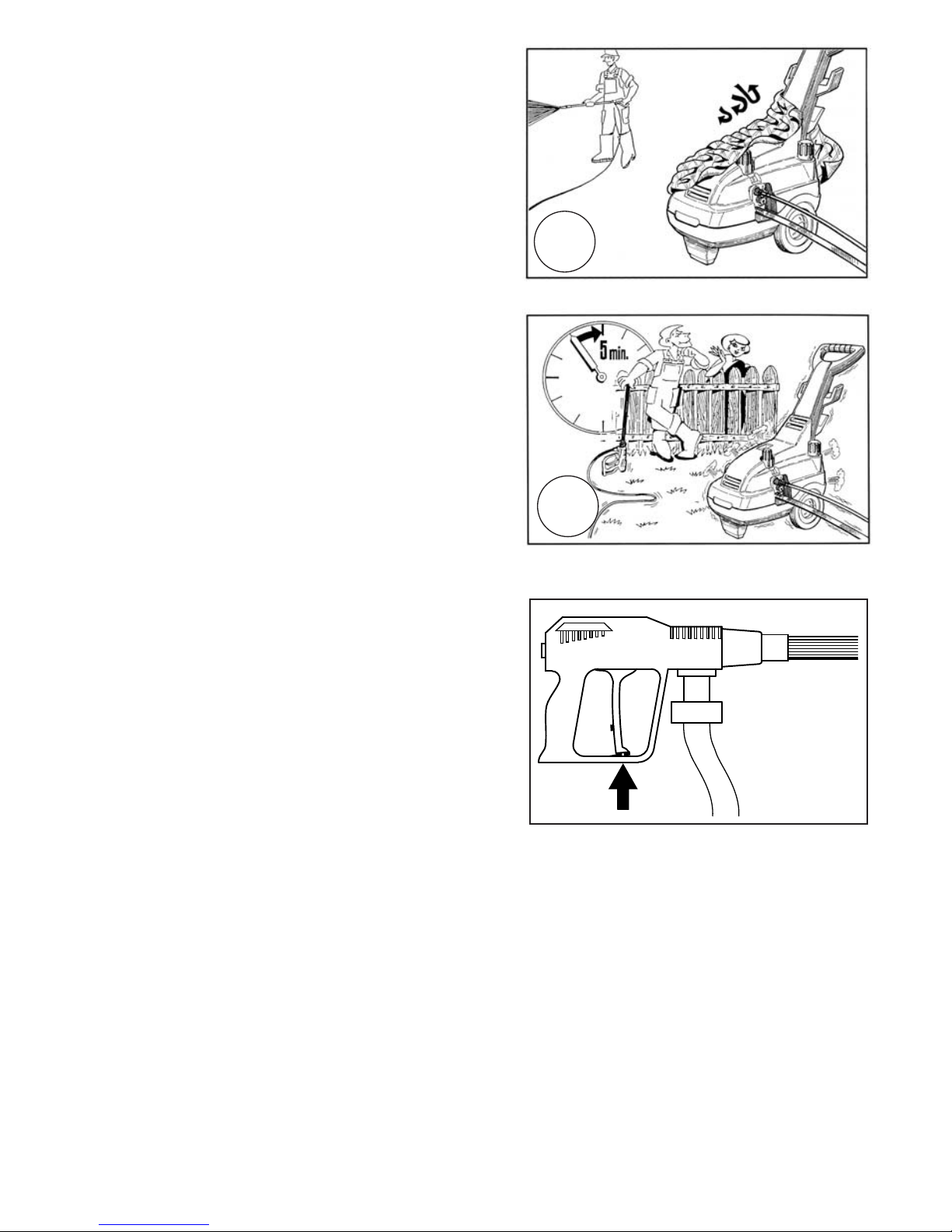
When the machine is off insert the safety
device on the gun to avoid accidental opening.
To ensure the security of the machine, use only original spare parts and accessories supplied
by the manufacturer.
THE MANUFACTURER CANNOT BE HELD RESPONSABLE FOR ANY DAMAGE CAUSED BY DISRESPECTING THE DESIGNATED USES OF THIS
MACHINE, IT'S INSTRUCTIONS AND WARNINGS INDICATED IN THIS
BOOKLET.
Do not leave the machine running for more
than 5 minutes with the pistol closed. After
this time period the water temperature within
the machine increase and may cause damage
to the machine.
NO
NO
Page 19
20
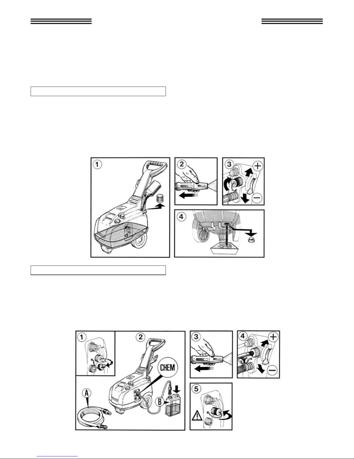
7 - HOW TO USE CHEMICAL PRODUCTS
The models T and TX can suck detergents and other liquid additives from the built-in tank or
from a separate tank.
In the event of direct contact with detergent additives, follow instructions provided by the manufacturer and/or product retailer and rinse the affected body part with clean water.
7.1 - SUCTION FROM INTERNAL TANK
Fill the tank, as shown in Fig. 1. Select the low pressure by operating the Rototek or
Multireg 99 (Fig. 2).
Make sure that the outer chemical ports is plugged (Fig. 3).
Adjust the chemical quantity by using the suitable cursor +/- (Fig. 3).
In order to empty the tank, open the plug located at the bottom of the machine (Fig. 4).
Capacity of the built-in tank: 7,5 litres.
7.2 - SUCTION FROM EXTERNAL TANK
Remove the plug from the chemical port (Fig. 1). Fit che connector of kit “A” into the chemical port (CHEM) and plunge the filter into the separate tank “B” (Fig. 2).
Select the low pressure by operating the Rototek or Multireg 99 (Fig. 3). Adjust the chemical
quantity by using the cursor +/- (Fig. 4). When you have finished working, remove kit “A” from
the chemical port and reinsert the plug (Fig. 5).
Page 20
21
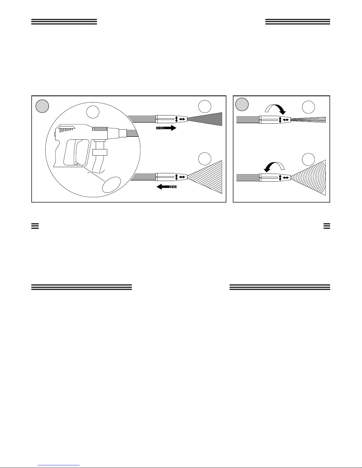
8 - USE OF ROTOTEK OR MULTIREG 99
9 - PRECAUTIONS AGAINST FREEZING AND INSTRUCTIONS FOR STORAGE
If the machine is stored where temperatures fall below the freezing level, it is advisable to suck
antifreeze (similar to that used for automobiles) into the pump before storage. In any case keep
the machine in a warm room for a couple of minutes before use.
OFF
2
1
3
HL
HL
4
5
HL
HL
A
B
Pressure selection must be carried out with closed pistol (1)
A - selection of the pressure
• High pressure (2)
• Low pressure (3)
B - selection of the jet
• straight pin jet (4)
• fan jet (5)
10 - MAINTENANCE
• Maintenance and repairs should always be performed by trained and authorised personnel.
• Before carrying out any cleaning, maintenance and/or parts replacement, disconnect the
machine from the power mains, removing the plug from the power outlet.
• Proper maintenance favours a longer duration of operation and improved performance.
• Periodically check the conditions of the washer, pressurised parts (pipe, fittings, lance) and
the electrical cable (see "General warnings for use").
Check for any water or oil leaks and/or malfunctions.
If necessary, replace affected parts.
The list of specific machine components and circuit diagrams are contained in the booklet
"SPARE PARTS NOMENCLATURE".
Contact Interpump Group customer service in the event of any doubts.
Page 21
22
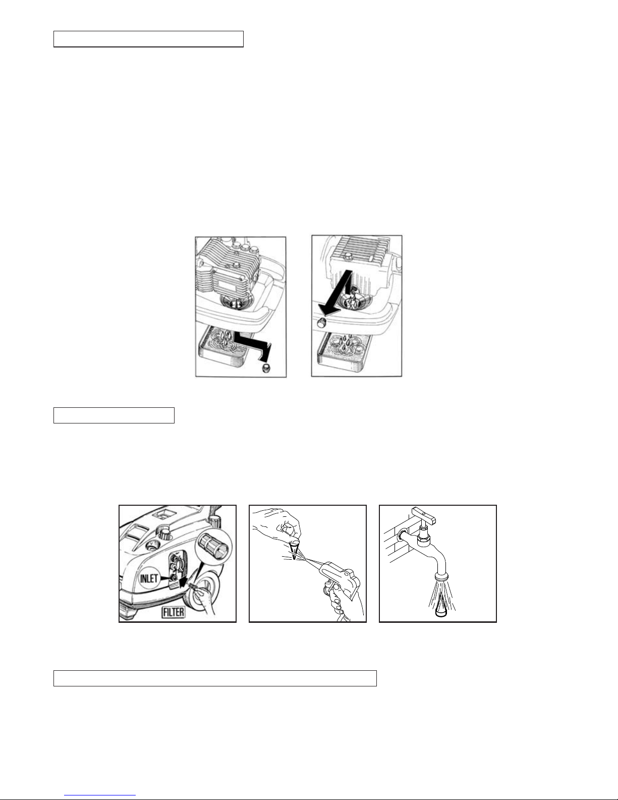
10.1 - OIL CHECK AND CHANGE
• The oil level must be checked periodically through the oil sight glass
• Oil must be changed after the first 50 hours of operation of the machine. Subsequent oil
changes must be carried out every 300 hours of machine operation.
• In any case it is advisable to change the oil at least once a year.
• Oil type: SAE 15W40 MINERAL
• Oil capacity: 0,33 liters T series
0,40 liters TX series
• Unscrew the drain plug on the bottom of the pump and the black/yellow dipstick on top.
• Collect the used oil in a tank and convey it to an authorized collection center.
• Replace the drain plug and fill in the oil up the level as shown in the oil level gauge.
• Replace the black/yellow dipstick.
10.2 - INLET FILTER
Before using the machine it is IMPORTANT to make sure that the filter is clean. Wash the filter under running water and/or with an air pressure gun to totally eliminate any deposits in the
filter.
Remember that a clean filter guarantees the good of the machine operation.
Remove the filter from the
water inlet
Clean the filter using an air
pressure gun.
Clean the filter under run-
ning water.
10.3 - REPLACEMENT OF HIGH PRESSURE NOZZLE
Periodically it is necessary to replace the high pressure nozzle as this is a component subject
to normal wear during use. This wear can generally be noticed by a decrease of the working
pressure. Contact your dealer if you wish to purchase a new nozzle.
T
TX
Page 22
23
11 - DISPOSAL OF THE MACHINE
• In case of no further use of the machine, it is advisable to disconnect the power cord making the machine inoperative.
• Keep out of reach of children.
• This machine is considered "special waste", disassemble and gather homogeneous parts for
recycling.
• Do not used recycled parts as spare parts.
IInnffoorrmmaattiioonn oonn tthhee ddiissppoossaall ooff eelleeccttrriicc aanndd eelleeccttrroonniicc
eeqquuiippmmeenntt iinn ccoommpplliiaannccee wwiitthh ddiirreeccttiivvee 22000022//9966 CCEE
((RRAAEEEE))..
11.. WWiitthhiinn tthhee EEuurrooppeeaann UUnniioonn
Warning: do not use the normal house trash bin to dispose of this
product.
Used electric and electronic equipment must be handled separately
and in compliance with the regulations relating to the treatment,
recovery and recycling of the said products.
In accordance with the regulations applied in the member States, private users resident in the EU can take used electric and electronic
equipment free of charge to designated collection centers*. In some
countries * the local dealer, too, can withdraw the old product free of
charge if the user purchases a new, similar product.
* For more information contact your local campetent authorities.
If you experience difficulties in locating an authorized disposal center,
consult the dealer from whom you purchased the product.
The correct disposal of this product will contribute to ensure that the waste is submitted to the
required treatment, recovery and recycling, preventing the potential negative impact on environment and human health, which could be caused by an unsuitable disposal of the waste.
The national regulations provide sanctions against whoever unlawfully disposes of or abandons
waste of electric or electronic equipment.
22.. IInn ccoouunnttrriieess oouuttssiiddee tthhee EEuurrooppeeaann UUnniioonn..
If you wish to dispose of this product, contact your local authorities to get information about the
correct disposal method.
Warning: the product
is marked with this
symbol, which means
that electric and electronic products should
not be disposed of
with the normal
house-hold waste. A
separate collection
system is foreseen for
these products.
Page 23
24
12 - TROUBLE SHOOTING
(FOR QUALIFIED PERSONNEL)
TROUBLE
CAUSE REMEDY
The pump is running but
maximum pressure is
not obtained
Air suction
Worn or dirty valves
Unloader packings worn
Nozzle worn or incorrect
Piston packings worn
Dirty filter
Check suction hose and fittings
Clean or substitute
Check and/or substitute
Check and/or substitute
Check and/or substitute
Check and/or clean
Fluctuating pressure Damaged, dirty or clogged valves
Air is being sucked
Worn packings
Dirty filter
Check, clean and/or substitute
Check suction hose and fittings
Check and/or substitute
Check and/or clean
Pressure decreases
Worn nozzle
Dirty or stuck valves
Bypass packings worn
Piston packing worn
Dirty filter
Substitute nozzle
Check, clean and/or substitute
Check and/or substitute
Check and/or substitute
Check and/or clean
Excessive noise Air suction
Damaged, dirty or stuck valves
Worn bearings
Water temperature too high
Dirty filter
Check suction hose and fittings
Check, clean and/or substitute
Check and/or substitute
Lower water temperature to
under 60°C
Check and/or clean
Worn water and oil seals Seals (water and oil) damaged
Excessively high ambient humidity
Check and/or substitute
Change oil twice as frequently
as advised
Water leakage from manifold Piston-packings-worn
O-rings worn
Replace washers
Replace O.R.
Oil leakage
Oil seal worn
Replace oil seal
The motor does not start when
switched on
The plug is not well connected
No power supply
Check plug, cord and switch
The motor stops The thermal protector has turned
the machine off for overheating
Check that the voltage is correct.
Turn off and let cool down
for a few minutes
before turning on again
The motor hums but does not run
when turned on
System voltage is lower to the
minimum advised
The pump is stuck or frozen
Extension cord incorrect
Check that your power source
is adequate
See page 21
Consult the extension cord
table on page 15
Page 24
138
12 - INCONVENIENTI E RIMEDI
(AD USO DI PERSONALE QUALIFICATO)
INCONVENIENTI
CAUSE RIMEDI
La pompa gira ma non
raggiunge le pressioni
La pompa aspira aria
Valvole usurate o sporche
Guarnizioni valvola bypass usurate
Ugello inadeguato o usurato
Guarnizioni usurate
Filtro sporco
Controllare i condotti di aspirazione
Pulire o sostituire
Controllare e/o sostituire
Controllare e/o sostituire
Controllare e/o sostituire
Controllare e/o pulire
Oscillazioni irregolari di
pressione
Valvole usurate, sporche o bloccate
Aspirazione d’aria
Guarnizioni usurate
Filtro sporco
Controllare pulire e/o sostituire
Controllare i condotti di
aspirazione
Controllare e/o sostituire
Controllare e/o pulire
Calo di pressione
Ugello usurato
Valvole sporche o bloccate
Guarnizioni valvola bypass usurata
Guarnizioni usurate
Filtro sporco
Cambiare ugello
Controllare pulire e/o sostituire
Controllare e/o sostituire
Controllare e/o sostituire
Controllare e/o pulire
Rumorosità Aspirazione di aria
Valvole usurate, sporche o bloccate
Cuscinetti usurati
Temperature eccessive dell’ acqua
Filtro sporco
Controllare i condotti di
aspirazione
Controllare pulire e/o sostituire
Controllare e/o sostituire
Portare la temperatura
sotto i 60° C.
Controllare e/o pulire
Presenza di acqua nell’ olio Anelli tenuta (acqua e olio) usurati
Alta percentuale di umidità nell’ aria
Controllare e/o sostituire
Cambiare l’olio con frequenza
doppia rispetto a quella prescritta
Perdite d’acqua dalla testata Guarnizioni usurate
O.R. del sistema di tenuta usurati
Sostituire le guarnizioni
Sostituire gli O.R.
Perdite d’olio
Anelli di tenuta olio usurati
Sostituire anelli di tenuta
Premendo l’interruttore il motore
non parte
La spina non è bene inserita
Manca corrente
Controllare spina, cavo e
interruttore
Il motore si arresta
improvvisamente
Il protettore termico è intervenuto
a causa di surriscaldamento
Controllare che la tensione sia
quella prescritta
Lasciare raffreddare per alcuni
minuti prima di riaccendere la
macchina
Premuto l’interruttore il motore
ronza ma non parte
La tensione (Volt) di rete è inferiore a
quella minima prescritta
La pompa è bloccata o gelata
Prolunga elettrica di inadeguata sezione
Controllare che l’impianto sia
adeguato
Vedere istruzioni a pag. 135
Consultare la tabella per l’uso
corretto della prolunga (pag. 129)
Page 25

KONFORMITÄTSERKLÄRUNG (Gemäß Anhang II der europäischen Richtlinie 2006/42/EG)
Der Hersteller INTERPUMP GROUP S.p.A. - Via E. Fermi, 25 - 42049 S. ILARIO D’ENZA (RE) - Italien
ERKLÄRT HIERMIT, dass die nachstehend definierte und beschriebene Maschine
Typ: Beweglicher Hochdruckreiniger
Fabrikat: INTERPUMP GROUP
Modell:
T-TX
entspricht den Anforderungen folgender EWG Richtlinien und Normen und der nachfolgenden Ergänzungen:
- Maschinenrichtlinie 2006/42 EWG
- Niederspannungsrichtlinie 2006/95/EWG
- Richtlinie für elektromagnetische Verträglichkeit 2004/108/EWG
- Richtlinie über die Produkthaftung des Herstellers 85/374 EWG
- Richtlinie über die Einschränkung der Verwendung bestimmter schädlichen Werkstoffen 2002/95 EWG
- Ricthtlinie über Elektro- und Elektronik-Altgeräte 2002/96/EG
- Richtlinie über Schallemissionen 2000/14 EWG
UNI EN ISO 12100.1:2005 • UNI EN ISO 12100.2:2005 • EN 60335.1:2002 + A1:2004 + A11:2004 + A2:2006 + A12:2006 • EN 60335.2.79:2009
Bevollmächtigte Person zur Zusammenstellung der Name:
Maurizio Novelli
technischen Unterlagen Anschrift:
INTERPUMP GROUP S.p.A.
Via E. Fermi, 25 - 42049 S. ILARIO D’ENZA (RE) - Italien
Bevollmächtigte Person zur Ausstellung der Erklärung:
Geschäftsführendes Verwaltungsratsmitglied
Ing. Paolo Marinsek
Reggio Emilia Dezember/2009 Unterschrift
____________________________________
DÉCLARATION DE CONFORMITÉ (Selon l'annexe II de la Directive Européenne 2006/42/CE)
Le fabricant INTERPUMP GROUP S.p.A. - Via E. Fermi, 25 - 42049 S. ILARIO D’ENZA (RE) - Italie
DÉCLARE que l’appareil identifié et décrit ci-après:
Type d’appareil: nettoyeur mobile haute pression
Marque d’origine: INTERPUMP GROUP
Modèle:
T-TX
Est conforme aux directives et normes indiquées ci-dessous et des mises à jour successives:
- Directive Machines 2006/42/ CE
- Directive basse tension 2006/95/ EC
- Directive sur la compatibilité électromagnétique 2004/108/ CE
- Directive sur la responsabilité du producteur 85/374 CE
- Directive sur la restriction d'utilisation de certaines substances dangéreuses 2002/95 CE
- Directive sur les déchets d'equipements électriques et électroniques 2002/96/CE (DEEE)
- Directive sur les émissions acoustiques 2000/14 CE
UNI EN ISO 12100.1:2005 • UNI EN ISO 12100.2:2005 • EN 60335.1:2002 + A1:2004 + A11:2004 + A2:2006 + A12:2006 • EN 60335.2.79:2009
Personne autorisée a constituer le dossier technique Nom:
Maurizio Novelli
Adresse
: INTERPUMP GROUP S.p.A.
Via E. Fermi, 25 - 42049 S. ILARIO D’ENZA (RE) - Italie
Personne ayant reçu pouvoir pour rédiger la déclaration: Administrateur Délégué
Ing. Paolo Marinsek
Reggio Emilia Décembre/2009 Signature
______________________________________
DECLARATION OF CONFORMITY (According to annex II of European Directive 2006/42/CE)
The manufacturer INTERPUMP GROUP S.p.A. - Via E. Fermi, 25 - 42049 S. ILARIO D’ENZA (RE) - Italy
DECLARES that the machine identified and described below:
Type of machine: Mobile High Pressure Cleaner
Factory mark: INTERPUMP GROUP
Model:
T-TX
Is in conformity with the requirement of the following CE directives and regulations and subsequent updates:
- Machine Directive 2006/42 CE
- Low voltage directive 2006/95/EC
- Electromagnetic compatibilty 2004/108/ CE
- Product liability directive 85/374 CE
- Reduction of hazardous substances (ROHS) directive 2002/95 CE
- Directive on waste electrical and electronic equipment 2002/96/CE (WEEE)
- Noise emissions directive 2000/14 CE
UNI EN ISO 12100.1:2005 • UNI EN ISO 12100.2:2005 • EN 60335.1:2002 + A1:2004 + A11:2004 + A2:2006 + A12:2006 • EN 60335.2.79:2009
Person authorized to compile the technical file Name:
Maurizio Novelli
Address:
INTERPUMP GROUP S.p.A.
Via E. Fermi, 25 - 42049 S. ILARIO D’ENZA (RE) - Italy
Person empowered to draw up the declaration: Managing Director
Ing. Paolo Marinsek
Reggio Emilia December/2009 Signature
______________________________________
 Loading...