

Interpump BOXJET TURBO 8.90, BOXJET TURBO 8.70, BOXJET TURBO 11.50, BOXJET TURBO 21, BOXJET TURBO 15 Operating Instructions Manual
...
• OPERATING INSTRUCTIONS
• MODE D’EMPLOI
• BEDIENUNGSANLEITUNG
• INSTRUCCIONES PARA EL USO
• MANUAL DE INSTRUÇÕES
• ИНСТРУКЦИЯ ПО ЭКСПЛУАТАЦИИ
• LIBRETTO ISTRUZIONI
• DO NOT USE THE MACHINE WITHOUT FIRST READING THE OPERATING INSTRUCTIONS
• N’UTILISER L’APPAREIL QU’APRÈS AVOIR LU LE MANUEL D’INSTRUCTIONS
• GERAT ERST NACH LESEN DER BEDIENUNGSANLEITUNG VERWENDEN
• NO UTILISE EL APARATO SIN LEER ANTES LAS INSTRUCCIONES PARA SU USO
• NÃO USE A MÁQUINA SEM LER A MANUAL DE INSTRUÇÕES
••
НЕ ИСПОЛЬЗУЙТЕ УСТРОЙСТВО, НЕ ПРОЧИТАВ СНАЧАЛА ИНСТРУКЦИЮ ПО ЭКСПЛУАТАЦИИ
• NON USARE LA MACCHINA SENZA AVERE LETTO LE ISTRUZIONI PER L’USO
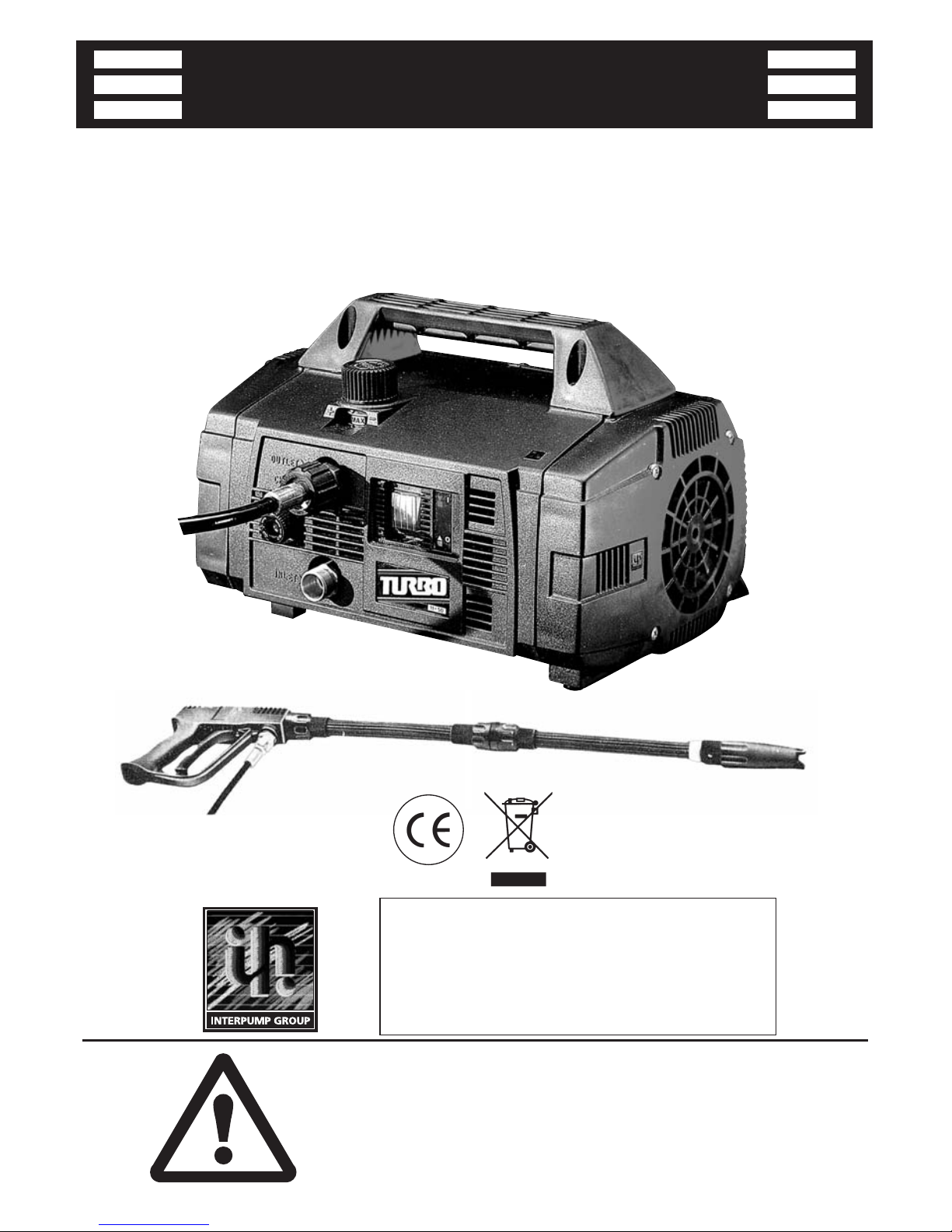
BBOOXXJJEETT
TURBO 8.70
TURBO 8.90
TURBO 11.50
TURBO 15
TURBO 19
TURBO 21


1
INDEX
ENGLISH
............................................................................................ pag.
FRANÇAIS
....................................................................................... pag.
DEUTSCH
......................................................................................... pag.
ESPAÑOL
........................................................................................... pag.
PORTUGUÉS
................................................................................ pag.
РУССКИЙ
......................................................................................... стр
..
ITALIANO
........................................................................................... pag.
PART LIST
........................................................................................ pag.
LISTE DE PIÈCES DÉTACHÉES
........................... pag.
ERSATZTEILLISTE
................................................................. pag.
LISTA DE REPUESTOS
.................................................... pag.
LISTA DE PEÇAS DE REPOSIÇAO
................... pag.
ВЕДОМОСТЬ ЗАПАСНЫХ ЧАСТЕЙ
........... pag.
NOMENCLATURA RICAMBI
..................................... pag.
OPTIONALS
......................................................................... pag.
4
20
36
52
68
84
100
117
117
117
117
117
117
117
128-129
2
• CONTROL DEVICES
Before connecting the machine to the water and electrical supplies, it is necessary to know the function of the controls
on the machine. This must be done in accordance with the descriptions in the Instruction Manual, taking
reference to the relevant instructions and illustrations.
• DISPOSITIFS DE CONTRÔLE
Avant de brancher l’appareil sur les réseaux d’alimentation d’eau et d’électricité, il est nécessaire de bien connaître le
fonctionnement de ses dispositifs de contrôle. Effectuer cette opération en vous référant aux instructions données
dans ce manuel et aux indications et illustrations y relatives.
• BEDIENUNGS - UND KONTROLLVORRICHTUNGEN
Bevor Sie das Gerät mit Wasser - und Stromanschlüssen verbinden ist es notwending, daß Sie die Bedienungs-und
Kontrollvorrichtungen des Gerätes verstehen. Bitte lesen Sie die Beschreibungen und Illustrationen der
Bedienungsanleitung.
• DISPOSITIVOS DE PUESTA EN MARCHA Y CONTROL
Antes de conectar el equipo a las redes de alimentación de agua y electricidad, es necesario conocer sus dispositivos
de puesta en marcha y control. Efectuar estas operaciones siguiendo las indicaciones que figuran en el manual de
istrucciones así como de sus ilustraciones grafícas correspondientes.
• DISPOSITIVO DE COMANDO E CONTROLO
Antes da ligação às redes de alimentação hídrica e eléctrica, é necessário saber qual a função dos dispositivos de
comando e controlo da máquina. Efectuar esta operação conforme descrito no Manual de Instruções.
• УСТРОЙСТВА УПРАВЛЕНИЯ
Перед тем, как подсоединить изделие к источникам воды и электроэнергии, необходимо изучить его
устройства управления. Это необходимо сделать в соответствии с описаниями, содержащимися в настоящей
Инструкции по экплуатации, уделяя внимание соответствующим инструкциям и иллюстрациям.
• DISPOSITIVI DI COMANDO E CONTROLLO
Prima dell’allacciamento alla rete di alimentazione idrica ed elettrica è necessario conoscere la funzione dei dispositivi
di comando e controllo della macchina. Effettuare questa operazione seguendo quanto descritto nel Manuale Istruzioni
facendo riferimento alle indicazioni e illustrazioni relative.
BBBBOOOOXXXXJJJJEEEETT
TT

3
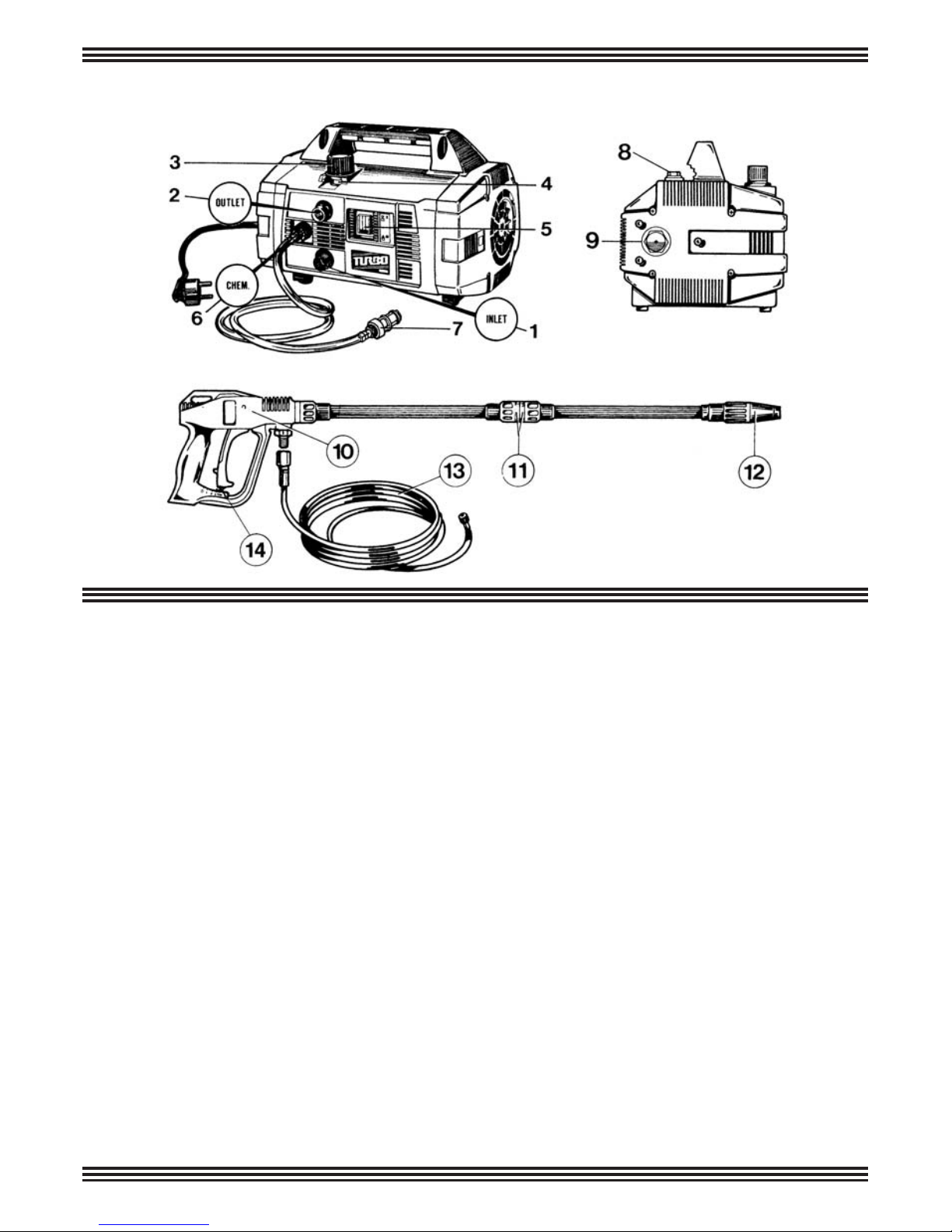
STANDARD EQUIPMENT
Inlet hose connection with water filter (INLET)
High pressure hose connection (OUTLET)
Pressure adjusting knob
Pressure indicator
ON/OFF switch
Chemical regulator (CHEM)
Chemical filter
Oil dipstick
Oil level indicator
Automatic gun
“QUICK-LANCE”
ROTOTEK (or “MULTIREG”)
High pressure hose
Safety lock
ÉQUIPEMENT STANDARD
Raccord d’alimentation eau et filtre (INLET)
Raccord de tuyau haute pression (OUTLET)
Bouton de régulation de la pression
Indicateur de pression
Interrupteur Marche/Arrêt
Molette de dosage du détérgent (CHEM)
Crépine du détérgent
Jauge de remplissage d’huile
Voyant du niveau d’huile
Pistolet automatique de sécurité
Lance à raccordement rapide “QUICK-LANCE”
ROTOTEK (ou “MULTIREG”)
Tuyau haute pression
Cran de sûreté
STANDARDAUSRÜSTUNG
Wasser-Anschluß mit Filter (INLET)
Hochdruck-Ausgang (OUTLET)
Druckregel-Griff
Druckanzeiger
EIN/AUS Schalter
Chemie-Dosierung (CHEM)
Chemie-filter
Ölmeßstab
Ölstandsanzeige
Spritzpistole
Wechsel-Lanze “QUICK-LANCE”
ROTOTEK (oder “MULTIREG”)
Hochdruckschlauch
Sicherheitssperre
EQUIPO STANDARD
Entrada + filtro agua (INLET)
Salida (OUTLET)
Mando de regulación de la presión
Manómetro
Interruptor
Mando de regul. del detergente (CHEM)
Filtro del detergente
Tapón de aceite con varilla de nivel
Mirilla nível de aceite
Pistola automática
Lanza “QUICK-LANCE”
ROTOTEK (o “MULTIREG”)
Tubo de alta presión
Seguro
EQUIPAMENTO STANDARD
Entrada de água com filtro (INLET)
Conector de saída de alta pressão (OUTLET)
Manípulo de ajuste de pressão
Indicador de pressão
Interruptor líg/des (ON/OFF)
Regulador de detergente (CHEM)
Filtro de aspiração de detergente
Tampa de óleo
Indicador de nivel de óleo
Pistóla automática
Lança
ROTOTEK (ou “MULTIREG”)
Mangueira de alta pressão
Travão
EQUIPAGGIAMENTO STANDARD
Entrata + filtro acqua (INLET)
Uscita (OUTLET)
Manopola di regolazione della pressione
Manometro
Interruttore
Pomolo di regolazione del detersivo (CHEM.)
Filtro detersivo
Tappo carico olio con asta di controllo
Spia livello olio
Pistola automatica
Lancia “QUICK-LANCE”
ROTOTEK (o “MULTIREG”)
Tubo alta pressione
Sicura
СТАНДАРТНОЕ ОБОРУДОВАНИЕ
Вход + Водяной фильтр
Выход (OUTLET)
Регулятор давления
Манометр
Выключатель
Регулировка моющего средства (CHEM)
Фильтр моющего средства
Пробка для заливки масла со стеклом для контроля
Индикатор уровня масла
Пистолет
Гидромонитор
Rototek или Multireg 99
Шланг высокого давления
Предохранитель

4
TABLE OF CONTENTS
1 - Description of symbols on the high pressure cleaner....................................... 5
2 - Technical specifications of the BOXJET............................................................ 6
3 - Product use....................................................................................................... 7
3.1 • Designated use................................................................................... 7
4 - Preliminary operations....................................................................................... 7
4.1 • Unpacking........................................................................................... 7
4.2 • Identification label............................................................................... 8
5 - Installation......................................................................................................... 8
5.1 • Connection high pressure outlet......................................................... 8
5.2 • Connection to water supply................................................................ 9
5.3 • Connection to electric system............................................................ 10
5.3.1 • Cut-out switch (Only the United States).......................................... 10
5.4 • Use of extention cord......................................................................... 11
5.5 • Start-up............................................................................................... 11
6 - General warnings.............................................................................................. 12
7 - Chemical product use....................................................................................... 15
8 - Use of "ROTOTEK" or "MULTIREG 99"............................................................ 15
9 - Precautions againt freezing, and instructions for storage.................................... 16
10 - Maintenance...................................................................................................... 16
10.1 • Oil change......................................................................................... 17
10.2 • Inlet filter............................................................................................ 17
10.3 • Replacement of high pressure nozzle ..............................................17
11 - Machine scrapping............................................................................................ 18
12 - Trouble shooting............................................................................................... 19
ENGLISH

5
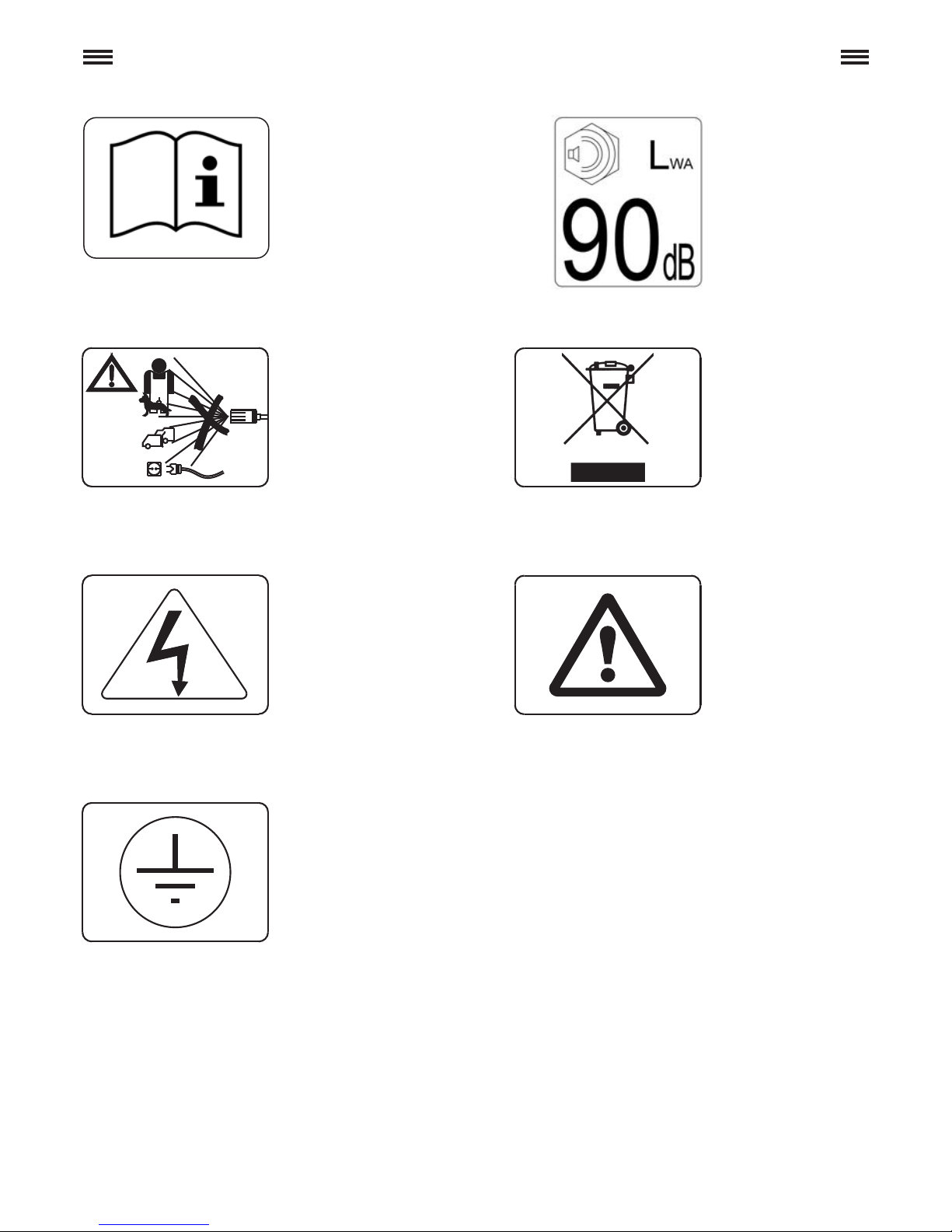
1 - DESCRIPTION OF SYMBOLS ON THE HIGH PRESSURE CLEANER
DDoo nnoott ddiirreecctt tthhee jjeett
aaggaaiinnsstt ppeerrssoonnss oorr
aanniimmaallss ppoowweerr oouutt--
lleettss oorr tthhee mmaacchhiinnee
iittsseellff..
WWaarrnniinngg!! RRiissk
k ooff
eelleeccttrrooccuuttiioonn
GGrroouunnddiinngg
SSppeecciiaall wwaassttee.. DDoo
nnoott ddiissppoossee ooff tthhiiss
pprroodduucctt iinn nnoorrmmaall
hhoouusseehhoolldd ggaarrbbaag
gee
WWaarrnniinngg ssiiggnn
RReeaadd tthhee iinnssttrruuccttiioonn
mmaannuuaall bbeeffoorree uussee..
GGaarraanntteedd ssoouunndd
ppoowweerr lleevveell..

6
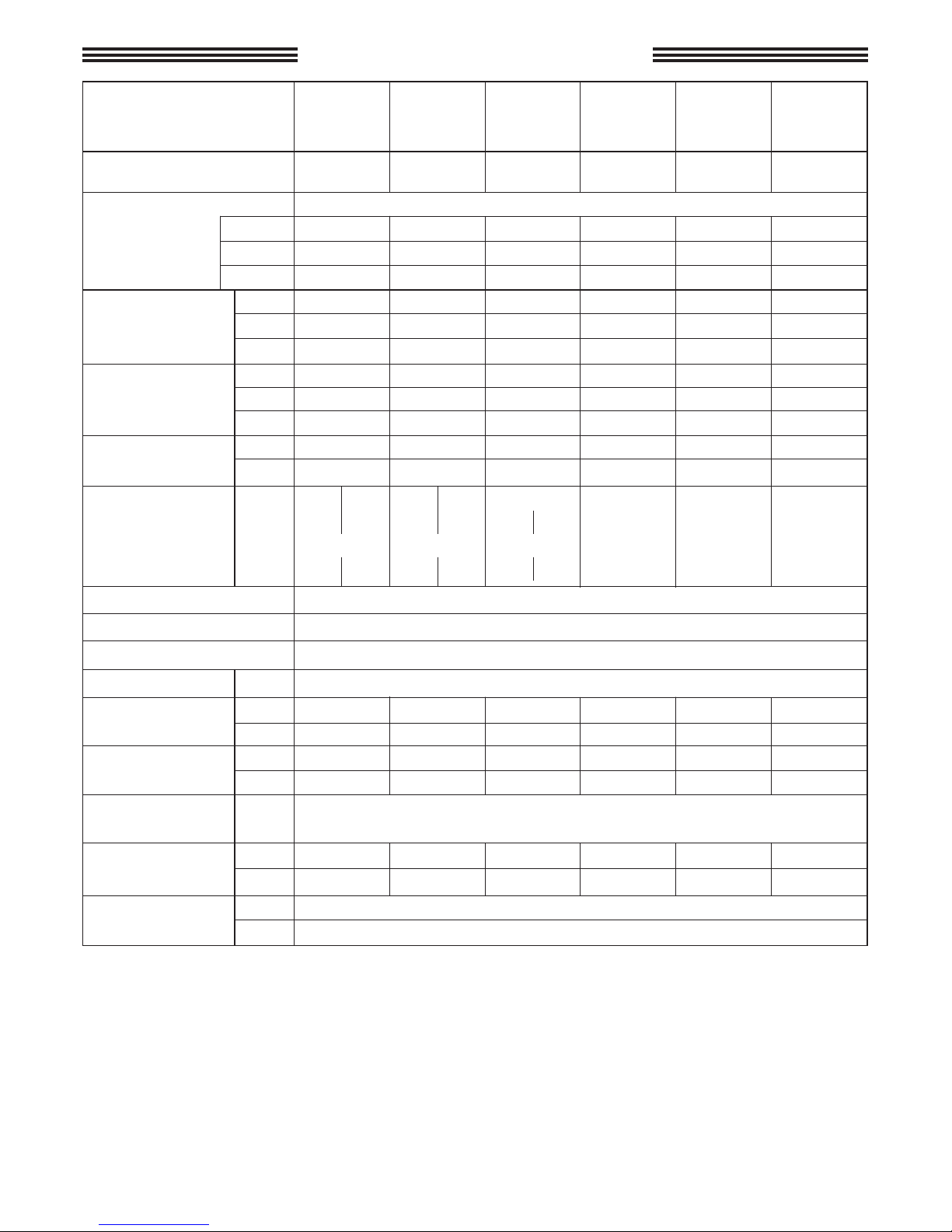
2 - TECHNICAL DATA
MODEL
Singlephase
motor power
kW.
Motor protection
Motor protection grade
°C
m/sec
2
Fixed nozzle A(8) than 2,5 - Rotating nozzle A(8) 3 (uncertainly 0,5)
Max. water inlet
temp
°F
m
Max suction depth
ft
High pressure hose
Thermoplastic material reinforced with nylon braid internal diameter 5/16”
Maximum working pressure 130 bar
Mass
Dimensions
mm
inches
Noise level
*
Lance vibration
*
P.S.I.
Overpressure
peak limit
Recoil thrust of jet
N
Flow rate
E.W. bar / MPa / P.S.I.: specific jet pressure in bar / MPa / P.S.I.
Equivalent
washing impact
with rotating
nozzle jet
E.W. MPa
E.W. P.S.I.
Working pressure
MPa
E.W. bar
bar
P.S.I.
MPa
bar
*
(Reference Standard EN60335-2-79)
8 m
26 ft
TURBO
21
TURBO
11-50
TURBO
8-70
TURBO
8-90
TURBO15TURBO
19
11 l/min.
8 l/min. 8 l/min. 8 l/min. 8 l/min.
2.11 G.P.M.
(USA)
10
14.5 16 12 13 13.8
100
145 160
120
130
138
1450
2100 2320
1750
1885
2000
50
70 90 55 60 70
5
7 9 5.5 6 7
725
1015
1300
800
870
1015
80
100 120
85
90
100
8
10 12
8.5
9
10
1160
1450 1750
1235
1300 1450
20
< 20
Current thermal overload
IPX5
Lp dB(A) 76 (uncertainly 1,5) - Lw dB(A) 90
60
11
1
11
3.3
360x240x235 (h)
14.2x9.4x9.2 (h)
Kg
2
< 2
20
2
< 20
< 2
< 20
< 2
< 20
< 2
V.
Hz.
A.
1,68 1,64 1,68 1,64 1,86 1,36 1,40 1,58
230
8,2
240
8
50
230
8,2
240
8
50
230
8,6
240
8,4
50
100
50
15
100
60
15
115
60
15
140
60 60 60 60
Kg
lbs
18,5 18,5 18,7 18,6 19,4
42.8

7
WE CONGRATULATE YOU on your choice that shows your level of technical knowledge and
love of beautiful objects.
In fact, you have purchased a highly technological machine produced by the world's
largest manufacturer of high pressure cleaner pumps.
This machine is so useful and versatile that you will use it for many years.
THIS BOOKLET IS AN INTEGRAL PART OF YOUR MACHINE AND SHOULD BE
CAREFULLY READ BEFORE PROCEEDING WITH INSTALLATION, START-UP AND
USE.
This booklet contains important safety information and instructions for use and maintenance
of the high pressure cleaners BOXJET and should be kept in a safe place.
3. PRODUCT USE
The machine is exclusively designed for washing, by way of a pressurized water jet, objects,
things or any surface suitable for cleaning by a pressurized water jet with the possibility of
adding liquid detergent.
ATTENTION: this appliance was designed for use of detergents recommended by the manufacturer. The use of other chemical products may jeopardize the safety of the appliance itself.
The liquid detergent additives must be chosen in consideration of the chemical compatibility
with the components of the pump and of the surface to be cleaned.
IMPORTANT: use only detergents that are biodegradable, and in any case complying with the
regulations applicable in the country where they are used.
3.1 DESIGNATED USE
4. PRELIMINARY OPERATIONS
4.1 UNPACKING
Unpack and make sure that the machine is complete and undamaged.
If the machine appears damaged in any way, do not use the machine and consult our dealer.
For shipping reasons some parts may be included separately. In this case assemble parts as
indicated in this booklet.
Keep all packaging materials (bags, boxes, tape) out of reach of children.
THE DESTINATION OF USE OF THIS MACHINE MUST BE STRICTLY ADHERED TO. ANY
OTHER USE MUST BE CONSIDERED AS INCORRECT.
THE MANUFACTURER CANNOT BE HELD RESPONSIBLE FOR DAMAGES CAUSED BY
INCORRECT USE OF THE MACHINE.
THE MACHINE MUST NOT BE TAMPERED WITH FOR ANY REASON. IN CASES OF
TAMPERING THE MANUFACTURER DECLINES ANY RESPONSABILITY ON THE FUNCTIONING AND SAFETY OF THE MACHINE.
IT IS FORBIDDEN TO STORE OR USE THE UNIT IN ENVIRONMENTS WITH POTENTIALLY EXPLOSIVE ATMOSPHERE.
8
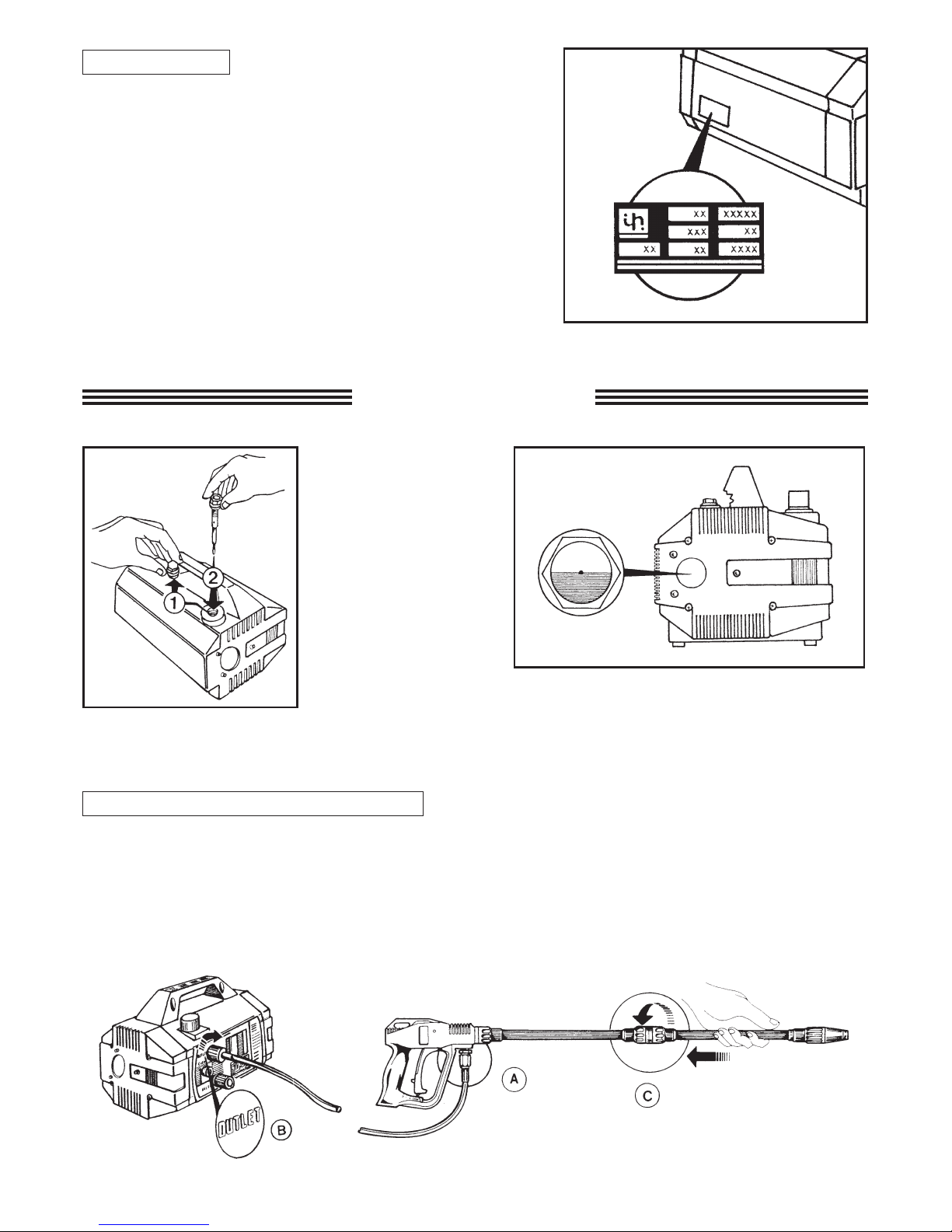
Before using this machine make sure that it has an ID
label. If it is without, do not use the machine and
consult your dealer immediately.
The identification label with technical specifications
is placed on the trolley and is always visible.
Check that ID label specifications correspond to
those required and that the power characteristics
for the outlet (V/Hz) are those shown on the label.
4.2 - ID LABEL
5 - INSTALLATION
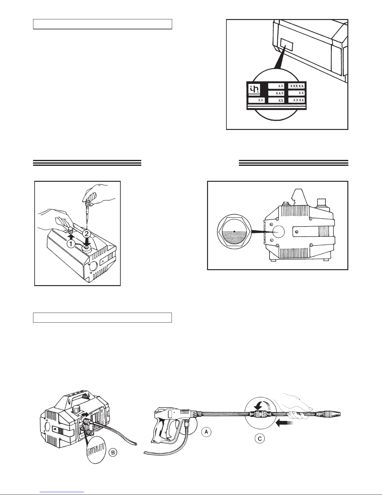
5.1 HIGH PRESSURE CONNECTION
Replace the red
travel plug (fig.1)
with the vented
black/yellow
dipstick provided
(fig.2).
Check that the oil in the sight glass is at
the half-way level (fig.3).
1- Connect one end of the high pressure hose to the gun (A) and the other to the outlet connection (B).
2- Assemble the lance by pushing the two halves together and then fix by turning the connector (C).
9
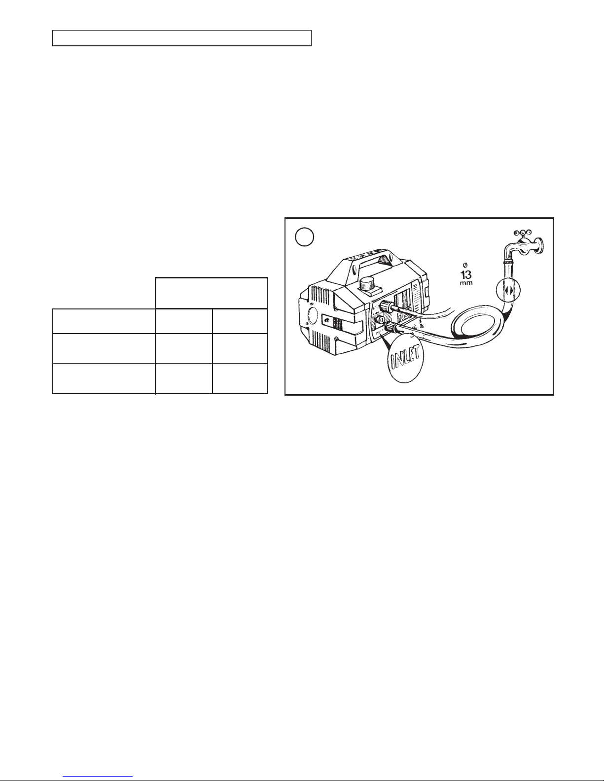
5.2 - CONNECTION TO THE WATER SUPPLY
1- The maximum temperature of the inlet water must not exceed 60°C (140°F).
2- Connect the water supply to the INLET port (D) by means of a reinforced hose (minimum
1,5 MPa - 15 bar - 200 psi) with internal diameter of no less than 13 mm. (1/2").
3- Since the water flow decreases according to the length of the hose, make sure that the quan-
tity of water supplied to the machine is not less than the quantities indicated in the chart
below.
4- The pressure of the inlet water must not exceed 1 MPa, 10 bar, 145 psi.
ATTENTION: The water supply which enters into the washer is not drinkable.
IMPORTANT
The water supplied to the machine must be clean. Running the unit without water, or with water
which is dirty, contains grit or corrosive liquids, causes serious damage to the machine.
If the user wishes to power the washer by means of free suction, simply emerge the end of the
supply tube in the water to be suctioned. The maximum suction depth considered as the distance in height between the water surface and the pump is 1m.
D
8•90 - 8•70
15 - 19 - 21
MODEL
L/min.
G.P.M. USA
11
15
2.9
4
11•50
FLOW RATE OF
WATER SUPPLY

10
5.3 - CONNECTION TO ELECTRICAL SYSTEM
1 - Check that the voltage of the electrical system (mains) is the same as indicated on the ID
label of the machine.
2 - Check that the plug complies with local safety regulations, and that it is provided with
ground connection (earth).
3 - Ensure that the outlet is protected by a "cut-out" (differential magnetic-thermal switch with
sensitivity of less than 30mA per 30ms) or that a device is present which can test the earthing
circuit.
4 - Do not connect other appliances to the same power outlet while using the machine.
5 - Insert the plug only after checking that the machine switch is in the OFF position.
6 - The standard plug for 50 Hz versions: SCHUKO 250V - 16A, standard CEE7-VII
DIN49441-2-AR2.
7- Fully unwind the power cord to prevent overheating.
8 - Do not crush on the power cord.
9 - Do not use the high pressure cleaner if the electric cable is damaged.
10 - If the power cord is damaged, its replacement can be effected only by the technical service personnel or by a qualified technician.
WARNING: IN CASE OF POWER FAILURE DURING OPERATION TURN OFF THE
UNIT FOR SAFETY REASONS.
5.3.1 - CUT-OUT SWITCH (Only the United States)
This UL version high-pressure washer is equipped with a cut-out switch contained in the power
cable plug.
Said equipment provides extra protection against the risk of electric shock.
When replacing the plug or cable, use the same components including the cut-out device.
11
5.4 - USE OF CORDS
If an extension cord is used, make sure that plug and receptacle are of a water-tight type. In
any case they must be raised from the ground in order to avoid possible contact with water.
Use only extension cables with the same number of conductors as those of the machine cable,
including the earthing cable, and with a suitable plug/socket for the cable used.
Only use extension cords for outdoor use. Said type of cable is marked "Suitable for outdoor
use." Store inside when not in use.
Do not use damaged extension cords. Cables should not be located near sources of heat or
sharp edges. Always disconnect the plug from the socket before removing the extension cord
from the product. Do not pull the cable to pull the plug out of the outlet. Do not touch the plug
or connections with wet hands.
WARNING
USE OF INADEQUATE
EXTENSION CORDS
MAY CAUSE SAFETY
HAZARDS
SELECTION TABLE
Voltage
220÷240
220÷240
100÷115
100÷115
Extension
cord length
Cord section
mm
2
Up to 20 m
From 20 to 50 m
Up to 20 m
From 20 to 50 m
1,5
2,5
2,5
4
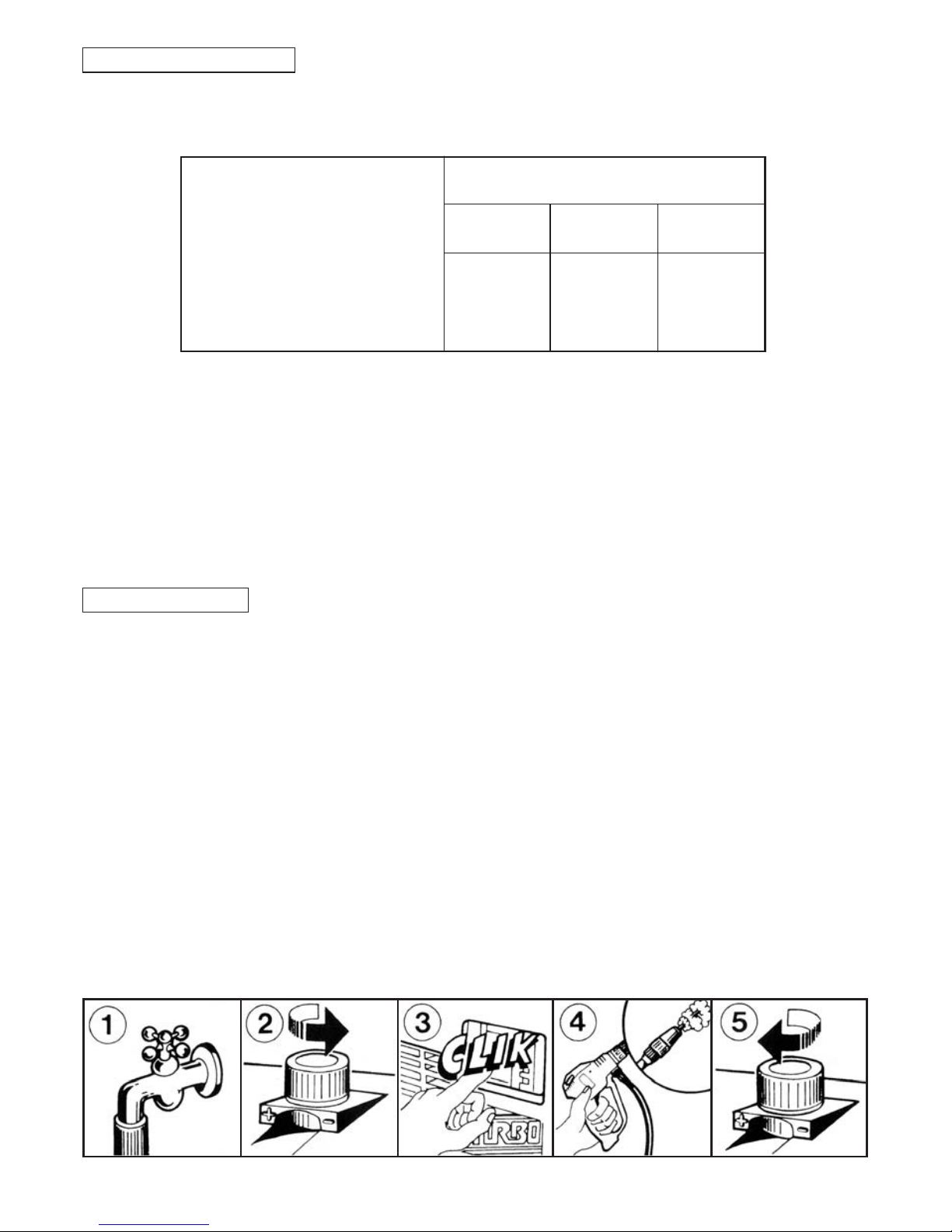
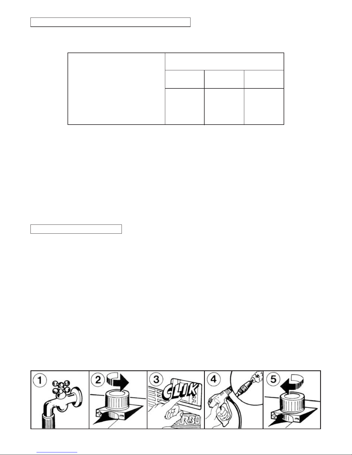
5.5 - START-UP
- Before starting up and using the machine, make sure that it is positioned on the ground or
leaning against a stable support and that the resting surface is level or with a minimum slope.
- It is ESSENTIAL to ensure that the suction filter is clean before use. (see maintenance chapter – 10.2 inlet filter).
1- Open water supply
2- Set the pressure to zero by turning the knob anti-clockwise.
3- Switch on the unit.
4- Hold the gun in the open position for a few seconds to allow the air to escape from hoses.
5- At this point adjust the machine to your pressure requirements and you are ready to enjoy
your work.
Attention! The water pressure at the outlet of the lance generates a force on itself;
therefore, grip the lance with both hands and with a secure grip.
- Switch off the machine when work is completed.
- Open the gun to release pressure still in the hose.
12
6 - GENERAL WARNINGS
High pressure cleaners can be used neither
by children nor by non authorized persons.
Children must be supervised to prevent them
from playing with the machine.
Keep this machine out of reach of children
at all times.
This equipment was not designed to be used
by persons with reduced physical, sensorial or
mental capabilities, or with limited experience
or knowledge, unless a person responsible for
their safety provides them with supervision or
the instructions for the use of the equipment.
NO
Only operate the machine in safety conditions, avoiding any potentially dangerous
situation for the user and others. The machine
operator should:
• Avoid to operate the machine on unbalanced
surfaces;
• Remember that the high pressure water jet
causes a recoil effect on the pistol. The recoil
values are indicated in the technical specifications table;
• Use protective clothing.
• Wear protective goggles and rubber slipproof boots
• Avoid dispersing substances that are polluting, toxic or harmful in any way.
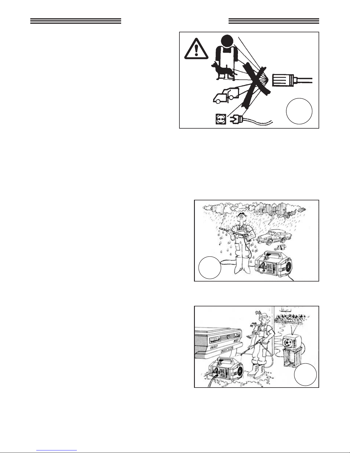
ATTENTION: Risk of explosion. Do not spray
flammable liquids.
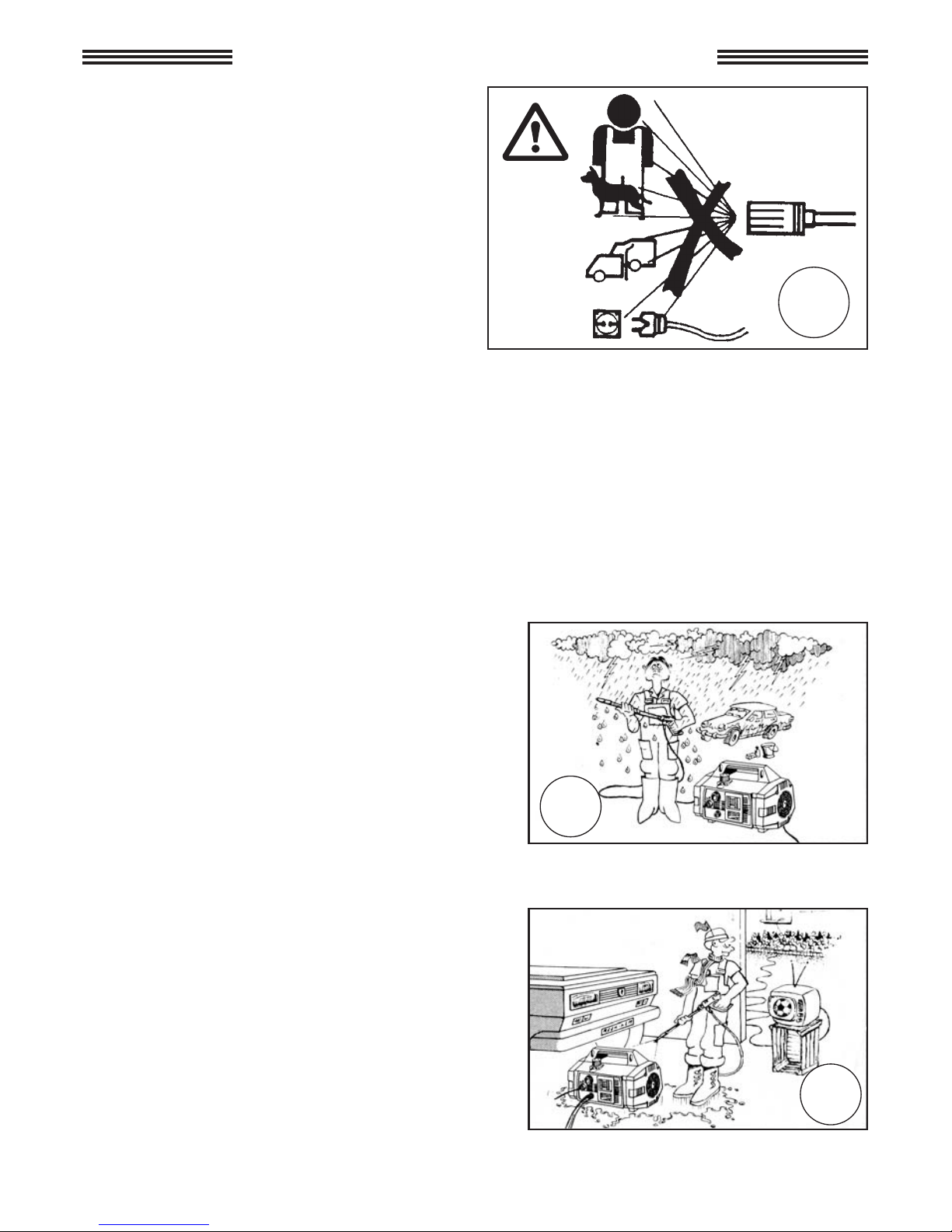
The high pressure water jet may be dangerous if used incorrectly. Never direct the jet at persons and/or animals, electrical appliances or the machine itself. Do not use the machine when
persons and/or animal are within the range of its high pressure jet.
Do not direct the jet against yourself or other persons to clean clothes or shoes.
NO
NO

13
This machine has been built in conformity
with current safety regulations. Use of electric
appliances requires the observations of a few
simple rules:
Do not touch electric parts when the machine
is on.
Inspection, maintenance and repairs should be
carried out by qualified personnel. In any case
unplug the machine before performing any of
the above operations.
Do not pull the cord to disconnect the power
supply and do not pull on the hose to move the
machine.
ATTENTION: high pressure flexible hoses,
high pressure connectors, safety devices,
electrical connections and spray guns are
important for the safety of the device.
Do not start the unit if the power cord is
damaged. Apply to qualified personnel for its
replacement. Replacement cords should have
the same technical specifications as the original cord. Do not carry out repairs on the electrical cord and avoid cord damage.
Do not start the unit if the high pressure hose, connectors and the gun are damaged. By
replacement make sure that the new components have at least the same rating as the original
components.The technical specifications of the hose should be printed on the hose itself (max
pressure, production date, manufacturer).
NO
NO
NO
14
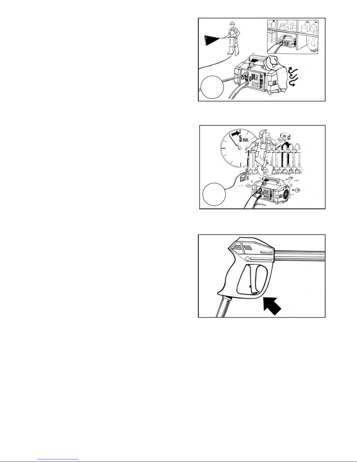
Avoid covering the machine during use and
use the machine in a well ventilated area.
When the machine is off insert the safety
device on the gun to avoid accidental opening.
The unit is equipped with a thermal protector which trips and electrically disconnects the
motor when it overheats.
If this event occurs, turn the selection knob on
the unit to the "0" position (machine OFF).
Read carefully the troubleshooting guide before starting the unit again.
To ensure the security of the machine, use only original spare parts and accessories supplied
by the manufacturer.
THE MANUFACTURER CANNOT BE HELD RESPONSABLE FOR ANY DAMAGE CAUSED BY DISRESPECTING THE DESIGNATED USES OF THIS
MACHINE, IT'S INSTRUCTIONS AND WARNINGS INDICATED IN THIS
BOOKLET.
NO
NO
Do not leave the machine running for more
than 5 minutes with the gun closed. After this
time period the water temperature within the
machine increase and may cause damage to
the machine.
15
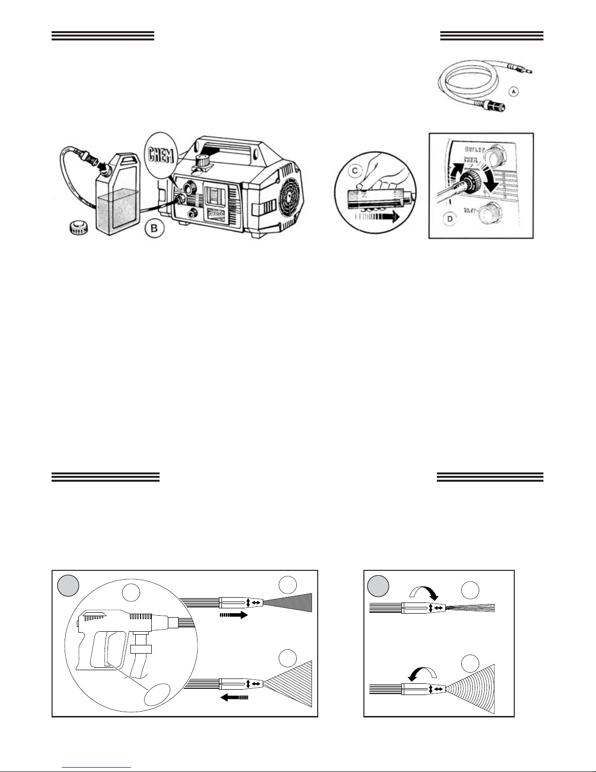
7 - HOW TO USE CHEMICAL PRODUCTS
The unit can suck and mix detergents and other liquid chemicals thanks
to an automatic device incorporated in the unit itself, which is remote
controlled by operating the ROTOTEK.
- The unit is equipped with a chemical suction kit (Fig. A).
- Fit the brass connector into the chemical control knob and filter into chemical container
(Fig.B).
- Select low pressure with the ROTOTEK (Fig. C).
- At this point the suction and mixing of the chemical will start automatically.
- You can regulate the quantity of chemicals by adjusting the chemical control knob (Fig. D).
- When you wish to stop using chemicals in order to clean on rinse, simply release the gun
trigger and adjust the ROTOTEK to high pressure.
At this point the chemical injection automatically stops.
If you foresee not using the unit for a long period of time, we suggest to clean the chemical
suction kit with clear water to avoid chemical deposit build-up.
Attention! In the event of direct contact with detergent additives, follow instructions provided
by the manufacturer and/or product retailer and rinse the affected body part with clean water.
8 - USE OF ROTOTEK OR MULTIREG 99
Pressure selection must be carried out with closed gun (1)
A - selection of the pressure
• High pressure (2)
• Low pressure (3)
B - selection of the jet
• straight pin jet (4)
• fan jet (5)
OFF
2
1
3
HL
HL
4
5
HL
HL
A
B

16
9 - PRECAUTIONS AGAINST FREEZING AND INSTRUCTIONS FOR STORAGE
10 - MAINTENANCE
• Maintenance and repairs should always be performed by trained and authorised personnel.
• Before carrying out any cleaning, maintenance and/or parts replacement, disconnect the
machine from the power mains, removing the plug from the power outlet.
• Proper maintenance favours a longer duration of operation and improved performance.
• Periodically check the conditions of the washer, pressurised parts (pipe, fittings, lance) and
the electrical cable (see "General warnings for use").
Check for any water or oil leaks and/or malfunctions.
If necessary, replace affected parts.
The list of specific machine components and circuit diagrams are contained in this booklet.
Contact Interpump Group customer service in the event of any doubts.
If the unit is to be stored in a place where there is risk of freezing, or it is to remain unused for
more than three months, we recommend placing some anti-freeze solution into the pump, (a
normal anti-freeze as used in your vehicle is sufficient).
If in doubt at low temperatures or any long length of storage time, we suggest you turn the
motor with the key provided before starting, to release any possibilities of blockages from freezing or a build up of lime scale deposits.
Taking these precautions before starting will avoid damage to the unit.
Remember to remove the key before switching on.
17
• Check oil level periodically.
• Oil must be changed after the first 20 hours of operation of the machine. Subsequent oil
changes must be carried out every 150 hours of machine operation.
• In any case it is advisable to change the oil at least once a year.
• Used oil must be collected in containers and disposed of in special centres according to
current standards. It absolutely should not be discarded into the environment.
• Oil type: SAE 15W40 Mineral.
• Oil capacity: 0,33 liter.
10.1 - OIL CHANGE
10.3 - REPLACEMENT OF HIGH PRESSURE NOZZLE
Periodically it is necessary to replace the high pressure nozzle as this is a component subject
to normal wear during use. This wear can generally be noticed by a decrease of the working
pressure. Contact your dealer if you wish to purchase a new nozzle.
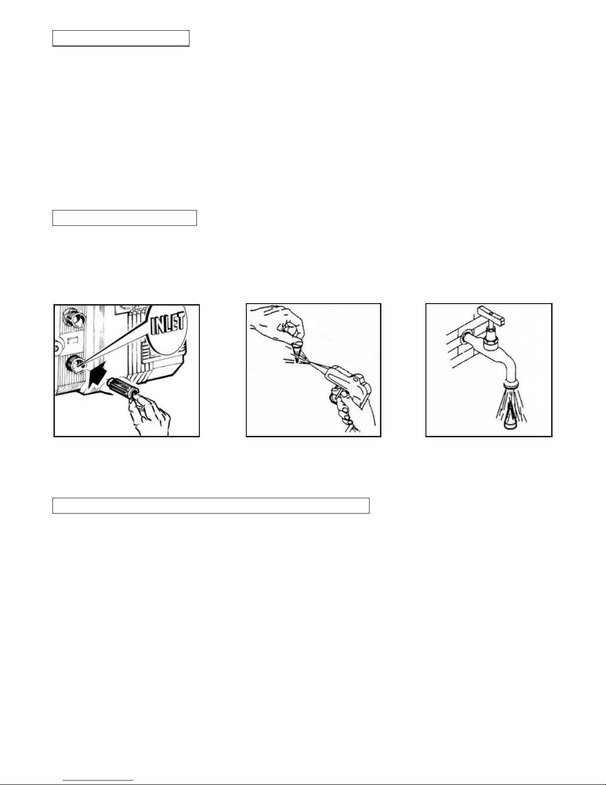
10.2 - INLET FILTER
Before using the machine it is IMPORTANT to make sure that the filter is clean. Wash the filter
under a water tap or blow it with air to remove completely all dirt particles.
Remember that a well-cleaned filter means good performance and long life for your machine.
Blow the filter with air.
Remove filter from water inlet.
Wash the filter under a water
tap.
11 - DISPOSAL OF THE MACHINE
• In case of no further use of the machine, it is advisable to disconnect the power cord making the machine inoperative.
• Keep out of reach of children.
• This machine is considered "special waste", disassemble and gather homogeneous parts for
recycling.
• Do not used recycled parts as spare parts.
IInnffoorrmmaattiioonn oonn tthhee ddiissppoossaall ooff eelleeccttrriicc aanndd eelleeccttrroonniicc
eeqquuiippmmeenntt iinn ccoommpplliiaannccee wwiitthh ddiirreeccttiivvee 22000022//9966 CCEE
((RRAAEEEE))..
11.. WWiitthhiinn tthhee EEuurrooppeeaann UUnniioonn
Warning: do not use the normal house trash bin to dispose of this
product.
Used electric and electronic equipment must be handled separately
and in compliance with the regulations relating to the treatment,
recovery and recycling of the said products.
In accordance with the regulations applied in the member States, private users resident in the EU can take used electric and electronic
equipment free of charge to designated collection centers*. In some
countries * the local dealer, too, can withdraw the old product free of
charge if the user purchases a new, similar product.
* For more information contact your local campetent authorities.
If you experience difficulties in locating an authorized disposal center,
consult the dealer from whom you purchased the product.
The correct disposal of this product will contribute to ensure that the waste is submitted to the
required treatment, recovery and recycling, preventing the potential negative impact on environment and human health, which could be caused by an unsuitable disposal of the waste.
The national regulations provide sanctions against whoever unlawfully disposes of or abandons
waste of electric or electronic equipment.
22.. IInn ccoouunnttrriieess oouuttssiiddee tthhee EEuurrooppeeaann UUnniioonn..
If you wish to dispose of this product, contact your local authorities to get information about the
correct disposal method.
Warning: the product
is marked with this
symbol, which means
that electric and electronic products should
not be disposed of
with the normal
house-hold waste. A
separate collection
system is foreseen for
these products.
18

19
12 - TROUBLE SHOOTING
(FOR QUALIFIED PERSONNEL)
TROUBLE
CAUSE REMEDY
The pump is running but
maximum pressure is
not obtained
Air sucked into pump
Worn or dirty valves
Unloader packings worn
Nozzle worn or incorrect
Piston packings worn
Dirty filter
Check suction hose and fittings
Clean or replace
Check and/or replace
Check and/or replace
Check and/or replace
Check and/or clean
Fluctuating pressure Damaged, dirty or clogged valves
Air is being sucked
Worn packings
Dirty filter
Check, clean and/or replace
Check suction hose and fittings
Check and/or replace
Check and/or clean
Pressure decreases
Worn nozzle
Dirty or stuck valves
Bypass packings worn
Piston packing worn
Dirty filter
Substitute nozzle
Check, clean and/or replace
Check and/or replace
Check and/or replace
Check and/or clean
Excessive noise Air suction
Damaged, dirty or stuck valves
Worn bearings
Water temperature too high
Dirty filter
Check suction hose and fittings
Check, clean and/or replace
Check and/or replace
Lower water temperature to
under 60°C
Check and/or clean
Presence of water in oil Piston packings and oil seals worn
High air humidity
Check and/or replace
Change oil twice as frequently
as that advised
Water dripping from under pump Piston packings worn
Packing o-rings worn
Check packings
Replace O.R.
Oil leakage
Oil seals worn
Replace oil seal
The motor does not start when
switched on
The plug is not well connected
No power supply
Check plug, cord and switch
The motor stops The thermal protector has tripped
due to overheating
Check that the mains voltage
corresponds to the specifications:
TURBO 8/70 - 8/90 - 11/50:
switch off the motor and let it
cool a few minutes
TURBO 15 - 19 - 21: wait a few
minutes before turning on the
unit again
The motor hums but does not run
when turned on
System voltage is lower to the
minimum advised
The pump is stuck or frozen
Extension cord incorrect
Check that your power source
is adequate
See page 16
Check the extension cord
table on page 11

20
FRANÇAIS
INDEX GÉNÉRAL
1 - Description des symboles sur le nettoyeur haute pression.............................. 21
2 - Caractéristiques techniques nettoyeur haute pression BOXJET...................... 22
3 - Utilisation du produit......................................................................................... 23
3.1 • Destination d’emploi........................................................................... 23
4 - Opérations préliminaires................................................................................... 23
4.1 • Déconditionnement............................................................................ 23
4.2 • Plaquette d'identification.................................................................... 24
5 - Installation......................................................................................................... 24
5.1 • Raccordement hydraulique................................................................. 24
5.2 • Branchement au réseau d’eau............................................................ 25
5.3 • Branchement au réseau électrique..................................................... 26
5.3.1 • Disjoncteur (Soulement pour les États-Unis)................................... 26
5.4 • Utilisation de rallonges de câble......................................................... 27
5.5 • Mise en fonction.................................................................................. 27
6 - Précautions générales d’emploi....................................................................... 28
7 - Comment utiliser les produits chimiques.......................................................... 31
8 - Comment utiliser le ROTOTEK ou le MULTIREG 99........................................ 31
9 - Précautions contre le gel et en cas d’inutilisation prolongeé........................... 32
10 - Entretien............................................................................................................ 32
10.1 • Vidange de l’huile.............................................................................. 33
10.2 • Filtre aspiration.................................................................................. 33
10.3 • Remplacement de la buse haute pression ...................................... 33
11 - Mise hors service de l’appareil......................................................................... 34
12 - Petit guide de dépannage................................................................................. 35
21
1 - DESCRIPTION DES SYMBOLES SUR LE NETTOYEUR HAUTE PRESSION
NNee ppaass ddiirriiggeerr llee
jjeett ccoonnttrree ddeess
ppeerrssoonnnneess oouu
aanniimmaauuxx,, pprriisseess
ddee ccoouurraanntt oouu
ll''aappppaarreeiill mmêêmmee..
AAtttteenntti
ioonn!! rriissqquuee
dd''éélleeccttrrooccuuttiioonn..
MMiissee àà tteerrrree..
DDéécchheett ssppéécciiaall.. NNee
ppaass éélliimmiinneerr ddaannss
lleess oorrdduurreess
mméénnaaggèèrrees
s..
SSiiggnnaall dd’’aatttteennttiioonn
LLiirree llee mmaannuueell
dd’’iinnssttrruuccttiioonnss
aavvaanntt ll’’uuttiilliissaa--
ttiioonn..
NNiivveeaauu ddee ppuuiiss--
ssaannccee ssoonno
orree
ggaarraannttii..
22
2 - CARACTÉRISTIQUES TECHNIQUES
MODÈLE
Puissance moteur
monophasé
kW.
Protection moteur
Degré d’étanchéité
°C
m/sec
2
Buse fixe A(8) petit diam. 2,5 - Buse rotative A(8) 3 (incertitude 0,5)
Température maxi de
l’eau d’alimentation
°F
m
Profondeur
maxi d’aspiration
ft
Tuyau
haute pression
Matériel thermoplastique, renforcé avec tresse en nylon.
Diamètre intérieur 5/16” - Pression de service 130 bars maximun.
Poids
Dimensions
mm
inches
Niveau sonore
*
Vibrations lance
*
P.S.I.
Surpression
admissible
Poussée de réaction
du jet (contrecoup)
N
Débit
E.W. bar / MPa / P.S.I.: pression spécifique du jet en bar / MPa / P.S.I.
Impact
équivalent jet
avec buse
Rototek
E.W. MPa
E.W. P.S.I.
Pression
d'exercice
MPa
E.W. bar
bar
P.S.I.
MPa
bar
*
Norme de référence EN60335-2-79
8 m
26 ft
TURBO
21
TURBO
11-50
TURBO
8-70
TURBO
8-90
TURBO15TURBO
19
11 l/min.
8 l/min. 8 l/min. 8 l/min. 8 l/min.
2.11 G.P.M.
(USA)
10
14.5 16 12 13 13.8
100
145 160
120
130
138
1450
2100 2320
1750
1885
2000
50
70 90 55 60 70
5
7 9 5.5 6 7
725
1015
1300
800
870
1015
80
100 120
85
90
100
8
10 12
8.5
9
10
1160
1450 1750
1235
1300 1450
20
< 20
Thermique ampèremétrique
IPX5
Lp dB(A) 76 (incertitude 1,5) - Lw dB(A) 90
60
11
1
11
3.3
360x240x235 (h)
14.2x9.4x9.2 (h)
Kg
2
< 2
20
2
< 20
< 2
< 20
< 2
< 20
< 2
V.
Hz.
A.
1,68 1,64 1,68 1,64 1,86 1,36 1,40 1,58
230
8,2
240
8
50
230
8,2
240
8
50
230
8,6
240
8,4
50
100
50
15
100
60
15
115
60
15
140
60 60 60 60
Kg
lbs
18,5 18,5 18,7 18,6 19,4
42.8

23
TOUTES NOS FÉLICITATIONS du choix que vous avez fait, qui témoigne le niveau de votre
connaissance technique et votre amour pour les belles choses.
Vous avez en effet acheté un appareil de haute technologie, fabriqué par le plus
grand constructeur mondial de pompes haute pression destinées au lavage.
Il s'agit d'un appareil utile et multi-fonctions, qui vous servira longtemps.
CE MODE D'EMPLOI FAIT PARTIE INTÉGRANTE DE L’APPAREIL. IL DOIT ÊTRE LU
ATTENTIVEMENT AVANT SON INSTALLATION, SA MISE EN SERVICE ET SON UTILISATION.
Ce mode d'emploi contient des indications et des instructions importantes concernant la
SÉCURITÉ d’UTILISATION et L'ENTRETIEN des nettoyeurs haute pression BOXJET. Il doit être
donc conservé soigneusement.
3. UTILISATION DU PRODUIT
L'appareil est destiné exclusivement au lavage, par des jets d'eau sous pression, d'objets et
de surfaces pouvant supporter l'action mécanique du jet sous pression, ainsi qu’une éventuelle
action chimique par addition de détergents liquides.
ATTENTION: cet appareil a été conçu pour être utilisé avec des détergents recommandés par
le constructeur. L’utilisation d’autres produits chimiques peut compromettre la sécurité de l’appareil même.
Les additifs détergents liquides devront être choisis selon des critères de compatibilité chimique
avec les composants de la pompe et de la surface à nettoyer.
IMPORTANT: utilisez uniquement des détergents biodégradables, et en tout cas conformes aux
normes en vigueur dans le pays où ils sont utilisés.
3.1 DESTINATION D’EMPLOI
4. OPÉRATIONS PRÉLIMINAIRES
4.1 DÉCONDITIONNEMENT
Enlevez l’appareil de son emballage et contrôlez qu’il est complet et intact. Dans le cas contraire, ne l'utilisez pas et adressez-vous au revendeur.
Pour des raisons d'emballage et de transport, certains accessoires peuvent être livrés non
montés. Dans ce cas, effectuez le montage suivant les instructions données dans ce mode
d'emploi.
Assûrez-vous que les éléments de l’emballage (pochettes, boîtes, éléments de fixation) sont
placés hors de la portée des enfants.
RESPECTER RIGOUREUSEMENT LES LIMITES DE L’EMPLOI AUQUEL CET APPAREIL
EST DESTINÉ. TOUTE AUTRE UTILISATION EST CONSIDERÉE NON CONFORME.
LE CONSTRUCTEUR NE PEUT ÊTRE CONSIDÉRÉ RESPONSABLE DES DOMMAGES
PROVOQUÉS PAR UNE UTILISATION NON CONFORME DE L’APPAREIL.
EN AUCUN CAS L’APPAREIL NE DOIT ETRE MODIFIÉ. LE CONSTRUCTEUR DÉCLINE
TOUTE RESPONSABILITÉ QUANT AU FONCTIONNEMENT ET À LA SÉCURITÉ DE L’APPAREIL SI CE DERNIER A ÉTÉ MODIFIÉ.
IL EST INTERDIT D’UTILISER ET DE STOCKER L’APPAREIL DANS DES LIEUX À
RISQUE D’EXPLOSION.
24
4.2 - PLAQUETTE D'IDENTIFICATION
5 - INSTALLATION
5.1 RACCORDEMENT HYDRAULIQUE
Avant d'utiliser l’appareil, contrôlez qu'il soit doté d'une
plaquette d'identification. Dans le cas contraire, n'utilisez pas l’appareil et signalez-le immédiatement au
revendeur.
La plaquette d'identification portant les caractéristiques techniques est placée sur le chariot et est toujors
visible.
Contrôler que les caractéristiques de la plaque d'identification correspondent à celles exigées et que les
caractéristiques du courant à la prise (V/Hz) soient celles indiquées sur la plaque d'identification.
Remplacez le
bouchon rouge
de voyage (fig. 1)
avec la jauge
jaune et noire(fig.
2) fournie avec
l'appareil.
Vérifiez que le niveau d'huile est au milieu
du voyant (fig. 3).
1- Raccordez le flexible haute pression au pistolet (A) et à la sortie haute pression (OUTLET) de
la pompe (B).
2- Emboîtez les deux parties de lance et vissez à fond (C).

25
5.2 - BRANCHEMENT AU RÉSEAU D’EAU
IMPORTANT
L’appareil doit toujours être alimentée avec de l'eau propre. Le fonctionnement sans eau ou
l'utilisation d'eau sale, sableuse ou contenant des produits chimiques corrosifs cause de
graves dégâts à l’appareil.
1- La température maximale de l'eau d’alimentation ne doit jamais dépasser 60°C (140°F).
2- Branchez le tuyau d'arrivée d'eau au réseau et au raccord d'arrivée d'eau INLET (D)
en utilisant un tuyau renforcé (min. 1,5 MPa - 15 bar - 200 psi) ayant un diamètre intérieur minimum de 13 mm. (1/2").
3- Comme le débit d'eau se réduit en fonction de la longuer du tuyau d’alimentation, veillez à
ce que le débit minimum qui alimente l’appareil est en conformité avec le tableau ci-dessous.
4- La pression maximale d'alimentation de la machine est de 1 MPa, 10 bar, 145 psi.
ATTENTION : l’eau d’alimentation contenue dans le nettoyeur doit être considérée non potable.
Si l’on désire alimenter le nettoyeur par aspiration libre, il suffit d'immerger l'extrémité du tuyau
d'alimentation dans l'eau à aspirer. La profondeur maximale d'aspiration, c'est-à-dire la hauteur
distante entre la surface libre de l’eau et la pompe est de 1m.
D
8•90 - 8•70
15 - 19 - 21
MODÈLE
L/min.
G.P.M. USA
11
15
2.9
4
11•50
DÉBIT RÉSEAU
HYDRIQUE

5.3.1 - DISJONCTEUR (Seulement pour les États-Unis)
Ce nettoyeur à haute pression dans la version UL est pourvu d’un disjoncteur inséré dans la
fiche du câble électrique. Ce matériel assure une ultérieure protection contre les risques de
décharge électrique.
En cas de substitution de la fiche ou du câble électrique, il faudra utiliser les mêmes composants, dont le disjoncteur.
26
5.3 - BRANCHEMENT AU RÉSEAU ÉLECTRIQUE
1. Vérifiez que la tension du secteur correspond à celle reportée sur la plaquette d'identification appliquée sur l’appareil.
2. Vérifiez que la prise de courant est conforme aux normes en vigueur dans le pays utilisateur
et en particulier, qu'elle est munie d’une prise de terre.
3. S’assurer que la prise soit protégée par un “disjoncteur” (interrupteur magnétothermique
différentiel avec stabilité inférieure à 30mA pour 30ms) ou bien qu’il y ait un dispositif qui puisse tester le circuit de terre.
4. Ne branchez pas d'autres appareils sur la à la même prise.
5. Branchez la fiche seulement après avoir vérifié que l'interrupteur de l’appar
eil se trouve sur
OFF.
6- La fiche standard pour les versions à 50 Hz est : de type SCHUKO 250V - 16A,
norme CEE7-VII DIN49441-2-AR2.
7- Dérouler complètement le câble électrique pour éviter les surchauffes.
8- Ne pas écraser le câble.
9- Ne pas utiliser le nettoyeur haute pression si le câble est endommagé.
10- Si le câble électrique est endommagé, son remplacement peut être effectué seulement par
le personnel d'assistance technique ou par un technicien qualifié.
ATTENTION: EN CAS D’INTERRUPTION DE COURANT PENDANT LE FONCTIONNEMENT, ÉTEIGNEZ L’APPAREIL POUR VOTRE SÉCURITÉ (OFF).
27
5.4 - UTILISATION DE RALLONGES DE CÂBLE
En cas d'utilisation d'une cable de rallonge, s’assûrer que la fiche et la prise sont du type
étanche. En tout cas il doivent être soulevés du sol afin d’éviter tout contact avec l’eau.
Utiliser exclusivement des rallonges qui ont le même nombre de conducteurs que le câble de
la machine, y compris celui de terre, et qui ont une fiche /prise adaptées au câble utilisé.
Utiliser exclusivement des rallonges pour usage externe. Ce type de câble est indiqué par la
mention « Adapté pour usage externe ».
Le conserver à l’intérieur lorsqu’il n’est pas utilisé.
Ne pas utiliser de rallonges détériorées. Ne pas laisser le câble à proximité des sources de
chaleur et des bords tranchants.
Retirer toujours la fiche de la prise avant de débrancher la rallonge de l'appareil.
Ne pas tirer sur le câble pour extraire la fiche de la prise. Ne pas toucher la fiche ni les
connexions avec les mains mouillées.
ATTENTION!
L'UTILISATION D'UNE
RALLONGE INADAPTÉE EST
SOURCE DE DANGER
TABLEAU DE SÉLECTION
Tension
Volts
220÷240
220÷240
100÷115
100÷115
Longueur
rallonge
Section câbles
en mm
2
20 m maximum
De 20 à 50 m
20 m maximum
De 20 à 50 m
1,5
2,5
2,5
4
- Avant de démarrer et d'utiliser la machine, s'assurer qu'elle soit placée au sol ou posée sur
un support stable, dans tous les cas la surface d'appui doit être horizontale ou très peu inclinée.
- Avant l’utilisation, il est IMPORTANT de s’assurer que le filtre d’aspiration soit propre (voir le
chapitre entretien – 10.2 filtre aspiration).
1- Ouvrez le robinet d'arrivée d'eau.
2- Amenez le bouton de réglage pression sur la position “0” zéro).
3- Appuyez sur l’interrupteur.
4- Tirez sur la gachette du pistolet quelques secondes afin d’evacuer l’air du tuyau.
5- À ce moment vous pouvez régler la pression à votre besoin.
Attention! L'eau en pression à la sortie de la lance génère une force sur celle-ci, donc
saisir la lance des deux mains et avec une prise sure.
- Éteindre la machine à la fin de l'opération.
- Ouvrir le pistolet pour décharger la pression encore présente dans le tuyau.
5.5 - MISE EN FONCTION
L'utilisateur devra veiller à toujours opérer
dans des conditions de sécurité, en évitant
toute situation de danger pour lui-même et les
autres. En particulier, il doit:
• éviter d'opérer dans des situations d'équilibre instable ou précaire;
• se rappeler que le jet sous pression produit
un recul sur la poignée du pistolet. Les valeurs
du recul sont reportées sur le tableau des
caractéristiques techniques;
• porter des vêtements de protection appropriés;
• porter des lunettes de protection et des
chaussures à semelle en caoutchouc antidérapante;
• ne pas disperser des substances polluantes
et toxiques dans l'environnement.
ATTENTION : Risque d’explosion, ne pas
pulvériser de liquides inflammables.
Les jets d’eau sous pression peuvent être dangereux s'ils sont utilisés de manière impropre.
En particulier, le jet ne doit jamais être dirigé en direction de personnes ou d'animaux, d'appareillages électriques ni vers l’appareil même.
N'utilisez pas l’appareil lorsque des personnes ou des animaux se trouvent dans son rayon
d'action. Ne pas diriger le jet contre vous-mêmes ou d'autres personnes pour nettoyer des
vêtements ou des chaussures.
6 - PRÉCAUTIONS GÉNÉRALES D’EMPLOI
Les nettoyeurs haute pression ne peuvent
être utilisés ni par des enfants ni par des personnes non autorisées. Les enfants doivent
être surveillés afin qu'il ne jouent pas avec
l'appareil.
Veillez à toujours tenir le nettoyeur hors de la
portée des enfants.
Cet appareil n'a pas été conçu pour être utilisé par des personnes ayant des capacités
physiques, sensorielles ou mentales réduites,
ou avec expérience ou connaissances
limitées, sauf qu'une personne responsable de
leur sécurité leur fournit une supervision ou les
instructions pour l'utilisation de l'appareil.
NO
28
NO
NO

29
L’appareil a été fabriqué conformément aux
règles de sécurité prévues par les normes en
vigueur. L'utilisation d'appareils électriques
comporte de toute façon le respect de certaines règles fondamentales, à savoir :
• ne pas toucher des parties électriques sous
tension,
• les opérations de contrôle, d'entretien ou de
réparation de l’appareil doivent être confiées à
un personnel qualifié. Débrancher toujours
l’appareil avant toute intervention sur celui-ci.
Ne tirez pas le câble d'alimentation pour
débrancher la fiche de la prise de courant et ne
tirez pas non plus le flexible haute pression
pour déplacer l’appareil.
ATTENTION: tuyaux flexibles et raccords
haute pression, dispositifs de sécurité, connections électriques, et poignée pistolets sont
importants pour la sécurité de l’appareil.
Ne pas démarrer l’appareil si le câble électrique est endommagé. S’adresser a un personnel qualifié pour son remplacement. Le câble
neuf devra avoir les mêmes caractéristiques
de celui d'origine, ces caractéristiques sont
reportées sur la gaine extérieure du câble.
N'effectuez aucune réparation précaire sur le
câble et veillez à ce qu'il ne soit pas endommagé.
Ne pas démarrer l’appareil si le tuyau haute pression, les raccords et la poignée pistolet sont
endommagés. En cas de remplacement s’ assûrer que les nouveaux composants ont aumoins
les mêmes caractéristiques que les composants d’origine. Les caractéristiques doivent être
reportées sur les flexibles (pression maxi d'exercice, date de fabrication, fabricant).
NO
NO
NO

Pour garantir la sécurité de l'appareil, utilisez seulement des pièces détachées et des acces-
soires originaux fournis par le constructeur.
LE FABRICANT DÉCLINE TOUTE RESPONSABILITÉ POUR TOUT
DOMMAGE CAUSÉ PAR LE NON RESPECT DES LIMITES D’EMPLOI ET DES
INSTRUCTIONS CONTENUES DANS CE MANUEL D’INSTRUCTIONS.
Ne couvrez jamais l’appareil pendant son
utilisation et travaillez toujours dans des
endroits bien ventilés.
Lorsq’on arrête l’appareil, engagez le cran
de sécurité sur le pistolet, afin d’eviter qu’il est
actionné par erreur.
L'appareil est équipé d'un protecteur thermique, qui intervient en débranchant électriquement le moteur en cas de surchauffage.
Si cet évent dévait se vérifier, tournez l'interrupteur de démarrage de l'appareil sur la position "0" (OFF).
Lisez bien le guide de dépannage avant de
démarrer l'appareil à nouveau.
30
NO
NO
Ne laissez pas fonctionner l’appareil plus de
5 minutes avec le pistolet fermé. Passé ce
délai, la température de l'eau en circuit augmente soudainement en risquant d'endommager les systèmes d'étanchéité.

31
7 - COMMENT UTILISER LES PRODUITS CHIMIQUES
L’appareil peut aspirer et mélanger des détergents et d’autres additifs
liquides grâce à un dispositif automatique intégré dans la machine et
actionné à distance en agissant sur le ROTOTEK.
- Vous trouverez dans l’emballage un kit d’aspiration du détergent (Fig. A).
- Emmancher le raccord en laiton dans la molette de dosage et plonger la crépine dans le
détergent (Fig. B).
- Mettre le ROTOTEK sur la position Basse Pression (Fig. C). À ce moment, lorsque vous
appuyez sur la gâchette, le détergent sera aspiré et mélangé automatiquement à l’eau.
- Vous pouvez augmenter ou diminuer la quantité du détergent en tournant la molette de
dosage (Fig. D).
- Quand vous voulez arrêter le détergent pour rincer/nettoyer, relâchez la gachette, agissez
simplement sur le ROTOTEK en l’amenant sur la position Haute Pression; à ce moment
l’aspiration ou détergent s’arrête automatiquement.
- En cas d’inutilisation prolongée de l’appareil, il est souhaitable de rincer le système
d’aspiration du détergent afin d’éviter des dépôts de produits chimiques.
Attention! En cas de contact direct avec les additifs détergents, suivre les indications fournies par le producteur et/ou revendeur du produit, et, toutefois, rincer abondamment la partie
du corps concernée avec de l’eau propre.
8 - COMMENT UTILISER LE “ROTOTEK” OU LE “MULTIREG 99”
Les sélections de la pression doivent s'effectuer avec le pistolet fermé (1).
A - sélection de la pression
• haute pression (2)
• basse pression (3)
B - Réglage du jet
• Jet droit (4)
• Jet plat (5)
OFF
2
1
3
HL
HL
4
5
HL
HL
A
B

9 - PRÉCAUTIONS CONTRE LE GEL EN CAS D’INUTILISATION PROLONGÉE
10 - ENTRETIEN
• L’entretien et les réparations doivent être exclusivement effectués par du personnel qualifié
et autorisé.
• Avant de pratiquer toute opération de nettoyage, d’entretien et/ou substitution de pièces de
rechange, débrancher la machine du réseau électrique en retirant la fiche de la prise de
courant.
• Un entretien correct favorise une durée de fonctionnement plus longue et le maintien des
meilleures performances.
• Contrôler régulièrement l’état du nettoyeur, des accessoires sous pression (tuyau, raccords,
lance) et du câble électrique (voir le chapitre “Mises en garde générales lors de l’utilisation”.
Vérifier les éventuelles fuites d’eau, d’huile et/ou dysfonctionnements.
En cas de besoin, pourvoir à la substitution des pièces défectueuses.
La liste des éléments qui composent la machine et les schémas électriques figurent à la fin
de ce manuel.
En cas de doute, contacter le service assistance Interpump Group.
32
Si l’appareil est rangé dans un endroit où il risque d’être exposé au gel, ou s’il est prévu de ne
pas l’utiliser pendant plus de 3 mois, nous conseillons l’aspiration préalable d’un liquide antigel comme celui utilisé pour les voitures.
En tout cas par températures très basses et si vous pensez que certains éléments de l’appareil peuvent être gelés, nous vous conseillons avant le démarrage, de faire tourner manuellement l’axe du moteur à l’aide de la clé jointe.
Cette opération permet de vérifier si l’apparel est gelé ou bloqué par des dépôts de calcaire.
En prenant ces précautions, on évite d’endommager l’appareil.
Penser à enlever la clé avant le démarrage de la machine.

33
• Le niveau d'huile doit être contrôlé périodiquement.
• La première vidange d'huile doit s'effectuer après les premières 20 heures d'exercice,
ensuite, toutes les 150 heures.
• Dans tous les cas, nous conseillons une vidange au moins une fois par an.
• L’huile usagée doit être recueillie dans des récipients et éliminée dans des centres spéciaux
conformément à la normative en vigueur. Elle ne doit en aucun cas être dispersée dans l'en
vironnement.
• Type d’huile: SAE 15W40 Minérale.
• Contenance d'huile: 0,33 litres
10.1 - VIDANGE DE L’HUILE
10.2 - FILTRE ASPIRATION
Avant de mettre en fonction l’appareil il est IMPORTANT de contrôler la propreté du filtre d'aspiration. Lavez-le soigneusement avec de l'eau ou nettoyez-le en y insufflant de l'air comprimé jusqu'à ce que tous les dépôts ont été éliminés.
Souvenez-vous qu'un filtre propre est la garantie d'un bon fonctionnement de l’appareil.
10.3 - REMPLACEMENT DE LA BUSE HAUTE PRESSION
Périodiquement il est nécessaire de remplacer la buse haute pression montée sur la lance, car
il s'agit d'un composant sujet à une normale usure de fonctionnement. L'usure de la buse est
généralement identifiable par une baisse de la pression de travail du nettoyeur. Pour le remplacement éventuel s'adresser à votre fournisseur et/ou à un révendeur pour des renseignements.
Nettoyez le filtre en y insufflant
de l'air comprimé.
Extraire le filtre du raccord d'arrivée de l'eau.
Lavez le filtre avec de l'eau
du robinet.

11 - MISE HORS SERVICE DE L’APPAREIL
• Si vous décidez de ne plus utiliser l’appareil, il est recommandé de le rendre inutilisable en enlevant le câble électrique.
• Dans tous les cas, tenez l’appareil hors de la portées des enfants.
• Comme ce matériel entre dans la catégorie des déchets spéciaux, il faut démonter et recuellir
les composants de même matière afin d’assurer leur élimination selon la règlementation en
vigueur.
• Ne pas utiliser ces composants usagées comme pièces de rechange.
IInnffoorrmmaattiioonnss ssuurr ll’’éélliimmiinnaattiioonn ddeess aappppaarreeiillllaaggeess éélleecc--
ttrriiqquueess eett éélleeccttrroonniiqquueess eenn ccoonnffoorrmmiittéé aavveecc llaa ddiirreeccttiivvee
22000022//9966 CCEE ((RRAAEEEE))..
11.. DDaannss ll’’UUnniioonn EEuurrooppééeennnnee
Attention: pour éliminer ce produit, ne pas utiliser la poubelle ordinaire.
Les appareillages électriques et électroniques usagés doivent être
gérés séparément et en conformité avec la législation régissant le
traitement, la récuparation et le recyclage de ces produits.
Suite aux dispositions en vigueur dans les États membres, les particuliers résidant en UE peuvent porter gartuitement les appareillages
électriques et électroniques usagés aux centres de récolte désignés
*. Dans certains Pays * le revendeur local peut lui aussi retirer gratuitement le vieux produit si l’utilisateur en achète un autre similaire.
* Pour plus de renseignements, veuillez contacter les autorités
locales compétentes.
En cas de difficultés pour trouver le centre de récolte autorisé à l’élimination, veuillez interpeller
le revendeur qui vous a vendu l’appareil.
L’élimination correcte de ce produit conatribuera à assurer que les déchets soient soumis au
traitement, à la récuperation et au recyclage nécessaires, en empêchant de cette façon l’impact
négatif potentiel sur l’environnement et sur la santé humaine, pouvant dériver d’une gestion
inappropriée des déchets.
La législation nationale prévoit des sanctions à la charge des sujets qui abandonnet ou éliminent les déchets d’appareillages électriques ou électroniques de façon illégale.
22.. DDaannss lleess ppaayyss aauu ddeehhoorrss ddee llaa UUEE..
Si vous désirez éliminer ce produit, veuillez contacter les autorités locales compétentes.
Attention: le produit
est marqué avec ce
symbole, qui signifie
que vous ne pouvez
pas éliminer les produits électriques et
électroniques avec les
ordures ménagères
ordinaires. Pour ces
produits est prévu un
système de récolte
séparé.
34

35
12 - PETIT GUIDE DE DÉPANNAGE
(SEULEMENT POUR PERSONNEL QUALIFIÉ)
PROBLÈME
CAUSES PROBABLES SOLUTIONS
La pompe marche mais ne donne
pas la pressions maxi.
La pompe aspire de l'air
Les clapets sont usés, sales ou bloqués
Joints de la soupape de bypass usés
Buse incorrecte ou usée.
Garnitures usés.
Filtre sale
Contrôler que le tuyau d’arrivée d’eau
est étanche
Contrôler, nettoyez ou remplacer
Contrôler, remplacer
Contrôler ou remplacer
Contrôler, remplacer
Contrôler eu nettoyer.
Oscillation de la pression. Les clapets sont usés, sales ou bloqués.
La pompe aspire de l'air.
Garnitures usées.
Filtre sale
Contrôler, nettoyer ou remplacer
Contrôler que le tuyau d’arrivée
d’eau est étanche
Contrôler, remplacer
Contrôler et nettoyer
Perte de pression
Buse usée.
Les clapets sont usés, sales ou bloqués.
Joint de la soupape de bypass usé
Garnitures usées.
Filtre sale.
Remplacer
Contrôler, nettoyez ou remplacer
Contrôler, remplacer
Contrôler, remplacer
Contrôler ou nettoyer.
Pompe bruyante La pompe aspire de l’air
Les clapets sont usés, sales ou bloqués
Roulements usés.
Température trop élevée de l’eau
Filtre sale.
Contrôler que le tuyau d’arrive d’eau
est étanche
Contrôler, nettoyer ou remplacer
Remplacer
Baisser la température de l’eau
Contrôler eu nettoyer
Présence d'eau dans l'huile Système d'étanchéité (eau-huile) usé
Haut pourcentage d’humidité dans l’air
Contrôler ou remplacer
Doubler la fréquence des
vidanges d'huile.
Fuite d'eau entre culasse et carter Système d’étanchéité usé Contrôler, remplacer
En appuyant sur l'interrupteur le moteur
ne démarre pas.
La prise est mal branchée.
Pas d'arrivée de courant
Contrôler prise, câble et
l'interrupteur.
Le moteur s'arrête La protection thermique est intervenue
à cause d’un échauffement
Contrôler que la tension d’alimentation correspond à celle prescrite
TURBO 8/70 - 8/90 - 11/50:
Éteindre l’interrupteur et laisser
refroidir l’appareil quelques minutes
TURBO 15 - 19 - 21: Attendre
quelques minutes avant de remettre
en service l’appareil.
En appuyant sur l'interrupteur le
moteur ronfle, mais ne démarre pas
La tension d’alimentation secteur est insuffisante
La pompe est bloquée ou gelée.
La section du câble de rallonge est
insuffisante
Contrôler le réseau électrique
Consulter pag.
32
Consulter le tableau pourr l'utilisation
correcte de la rallonge (pag.
27)

36
DEUTSCH
INHALTSVERZEICHNIS
1 - Beschreibung der Symbole des Hochdruckreinigers........................................ 37
2 - Technische Daten Hochdruckreiniger BOXJET ............................................... 38
3 - Gebrauch des Gerätes..................................................................................... 39
3.1 • Bestimmungszweck............................................................................ 39
4 - Vorbereitungen.................................................................................................. 39
4.1 • Auspacken...........................................................................................39
4.2 • Typenschild......................................................................................... 40
5 - Installation......................................................................................................... 40
5.1 • Hydraulischer Anschluß...................................................................... 40
5.2 • Anschluß an das Wasserversorgungsnetz.......................................... 41
5.3 • Anschluß an das Stromnetz................................................................ 42
5.3.1 • Schutzschalter (Nur für USA)........................................................... 42
5.4 • Verwendung von Verlängerungskabel................................................ 43
5.5 • Anlassen.............................................................................................. 43
6 - Allgemeine Gebrauchshinweise........................................................................ 44
7 - Verwendung von Reinigungsmittel................................................................... 47
8 - Über den Gebrauch von “ROTOTEK” oder “MULTIREG 99”........................... 47
9 - Maßnahmen im Falle von Einlagerungen und/oder Frost................................. 48
10 - Wartung............................................................................................................. 48
10.1 • Ölwechsel.......................................................................................... 49
10.2 • Saugfilter............................................................................................ 49
10.3 • Ersatz Hochdruckdüse...................................................................... 49
11 - Verschrottung des Gerätes............................................................................... 50
12 - Störungen und Abhilfen.................................................................................... 51

37
1 - BESCHREIBUNG DER SYMBOLE DES HOCHDRUCKREINIGERS
DDeenn SSttrraahhll nniicchhtt
ggeeggeenn PPeerrssoonneenn,,
TTiieerree uunndd
SSttrroommaannsscchhllüüssssee
ddeerr MMaasscchhiinnee
sseellbbsstt rriicchhtteenn..
VVoorrssiicchhtt.. GGeef
faahhrr
vvoonn SSttrroommsscchhllaagg
EErrdduunngg
SSoonnddeerraabbffaallll..
NNiicchhtt iinn ddeenn
ggeewwööhhnnlliicchheenn
AAbbffaallll wweerrffeenn..
WWaarrnnuunnggsszzeeiicchheenn
BBe
eddiieennuunnggssaannlleeiittuunngg vvoorr
ddeemm GGeebbrraauucchh lleesseenn..
SScchhaallllppeeggeell..

38
2 - TECHNISCHE DATEN
MODELL
Wechselstrommotorenleistung
kW.
Motorschutzschalter
Schutzgruppe
°C
m/sec
2
Feste Düse A(8) kleiner als 2,5 - Drehende Düse A(8) 3 (Ungenauigkeit 0,5)
Max.
Wasserzulauftemperatur
°F
m
Max. Saughöhe
ft
Hochdruckschlauch
Verstärkter thermoplastischer Schlauch mit Nylongeflecht; Nennweite 5/16”
Max. Betriebsdruck 130 bar
Masse
Abmessungen
mm
inches
Schallpegel
*
Vibrationen Lanze
*
P.S.I.
Zulässiger
Max. Überdruck
Rückstoßkraft
des Strahles
N
Fördermenge
E.W. bar / MPa / P.S.I.: spezifischer Strahldruck in bar / MPa / P.S.I.
Gleichwertiger
Renigungseffekt
des Strahles mit
Rotonozzle
E.W. MPa
E.W. P.S.I.
Max. Betriebsdruck
MPa
E.W. bar
bar
P.S.I.
MPa
bar
*
Bezugsnorm EN60335-2-79
8 m
26 ft
TURBO
21
TURBO
11-50
TURBO
8-70
TURBO
8-90
TURBO15TURBO
19
11 l/min.
8 l/min. 8 l/min. 8 l/min. 8 l/min.
2.11 G.P.M.
(USA)
10
14.5 16 12 13 13.8
100
145 160
120
130
138
1450
2100 2320
1750
1885
2000
50
70 90 55 60 70
5
7 9 5.5 6 7
725
1015
1300
800
870
1015
80
100 120
85
90
100
8
10 12
8.5
9
10
1160
1450 1750
1235
1300 1450
20
< 20
Strom-Thermoschutzschalter
IPX5
Lp dB(A) 76 (Ungenauigkeit 1,5) - Lw dB(A) 90
60
11
1
11
3.3
360x240x235 (h)
14.2x9.4x9.2 (h)
Kg
2
< 2
20
2
< 20
< 2
< 20
< 2
< 20
< 2
V.
Hz.
A.
1,68 1,64 1,68 1,64 1,86 1,36 1,40 1,58
230
8,2
240
8
50
230
8,2
240
8
50
230
8,6
240
8,4
50
100
50
15
100
60
15
115
60
15
140
60 60 60 60
Kg
lbs
18,5 18,5 18,7 18,6 19,4
42.8

39
GLÜCKWUNSCH! Daß Sie dieses Gerät gewählt haben, zeugt von Ihrer technischen Kenntnis
und für Ihren Geschmack für schöne Dinge!
In der Tat ist Ihre Entscheidung auf ein technologisch hochwertiges Gerät gefallen, das
vom größten Hochdruck-Plungerpumpen-Hersteller der Welt erzeugt wurde.
Es handelt sich um nützliche Geräte, die Ihnen langzeitig dienen werden.
DIESES HANDBUCH IST EIN INTEGRIERENDER BESTANDTEIL DES GERÄTES UND
MUSS VOR DER INSTALLATION, INBETRIEBNAHME UND VERWENDUNG AUFMERKSAM DURCHGELESEN WERDEN.
Dieses Handbuch enthält wichtige Angaben und Anleitungen für einen SICHEREN GEBRAUCH
und die WARTUNG der Hochdruckreiniger BOXJET und ist deshalb sorgfältig aufzubewahren.
3. GEBRAUCH DES GERÄTES
Das Gerät ist ausschließlich für die Reinigung mit Hochdruck-Wasserstrahl von Gegenständen
und Dingen bzw. auf jeden Fall von solchen Oberflächen bestimmt, die sich für die Behandlung
mit der mechanischen Wirkung des Hochdruck-Wasserstrahles und der eventuellen chemischen Wirkung flüssiger Reinigungsmittel eignen.
VORSICHT! Für dieses Gerät ausschließlich vom Hersteller empfohlene flüssige
Reinigungsmittel verwenden. Die Verwendung anderer Chemikalien kann die Sicherheit des
Gerätes beeinträchtigen.
Die flüssigen Reinigungsmittel müssen unter Berücksichtigung der chemischen Verträglichkeit
mit den Bestandteilen der Pumpe und der zu reinigenden Flächen gewählt werden.
WICHTIG: verwenden Sie ausschließlich biologisch abbaubare Reinigungsmittel. Diese müssen auf jeden Fall den im Verwendungsland geltenden Vorschriften entsprechen.
3.1 BESTIMMUNGSZWECK
4. VORBEREITUNG
4.1 AUSPACKEN
Das Gerät auspacken und sich vergewissern, daß es in einwandfreiem Zustand ist und keine
Schäden aufweist.
Andernfalls das Gerät nicht benutzen und den Händler verständigen.
Aus Verpackungs- und Transportgründen können einige Zubehörteile abmontiert sein; in
diesem Fall sind diese Teile unter Befolgung der in diesem Handbuch enthaltenen Anleitungen
zu montieren.
Vergewissern Sie sich, daß die Verpackungselemente (Beutel, Schachteln,
Befestigungselemente) nicht in die Reichweite von Kindern gelangen.
DIESES GERÄT DARF AUSSCHLIEßLICH NUR FÜR DEN VORGESEHENEN VERWENDUNGSZWECK EINGESETZT WERDEN. JEDE ANDERE VERWENDUNGSART IST ALS
UNSACHGEMÄß UND FOLGLICH ALS GEFÄHRLICH ANZUSEHEN.
DER HERSTELLER ÜBERNIMMT KEINE VERANTWORTUNG FÜR SCHÄDEN, DIE
DURCH UNSACHGEMÄßEN GEBRAUCH VERURSACHT WERDEN.
DAS GERÄT UND DIE DAZU GEHÖRENDEN TEILE DÜRFEN AUF KEINEN FALL IN
IRGENDEINER WEISE VERÄNDERT WERDEN. ANDERENFALLS LEHNT DER HERSTELLER JEDE VERANTWORTUNG AB, WELCHE DIE FUNKTIONSTÜCHTIGKEIT UND DIE
SICHERHEIT DES GERÄTES BETREFFEN.
ES IST VERBOTEN, DIE MASCHINE IN UMGEBUNGEN MIT POTENZIELL EXPLOSIVER
ATMOSPHÄRE ZU BENUTZEN UND ZU LAGERN.

40
4.2 - TYPENSCHILD
5.1 HYDRAULISCHER ANSCHLUß
Vergewissern Sie sich vor der Verwendung des Gerätes,
daß das Typenschild auf ihm vorhanden ist. Andernfalls
das Gerät nicht benutzen, sondern unverzüglich den
Händler verständigen.
Das Typenschild mit den technischen Daten ist auf dem
Wagen sichtbar befestigt.
Überprüfen, dass die Anforderungen mit den Angaben
auf dem Typenschild übereinstimmen, und die
Stromversorgung (V/Hz) den Eigenschaften auf dem
Typenschild entspricht.
5 - INSTALLATION
Ersetzen Sie die rote
Transportschraube (1)
durch den
mitgelieferten
schwarzgelben
Ölmeßstab (2) mit
Belüftung.
Überprüfen Sie, daß der Ölstand in der
Mitte des Ölschauglases (3) steht.
1- Stecken Sie die Lanze an die Pistole und drehen Sie die Überwurfmutter zwecks sicherer
Befestigung (A).
2- Verbinden Sie den Hochdruckschlauch mit dem OUTLET (B) und sichern Sie die Mutter
sorgfältig.

41
5.2 - ANSCHLUß AN DAS WASSERVERSORGUNGSNETZ
WICHTIG
Vergewissern Sie sich, daß das Gerät mit sauberem Wasser versorgt wird. Der Gerätebetrieb
ohne Wasser bzw. die Versorgung mit schmutzigem, sandhaltigem oder korrodierende chemischen Mitteln enthaltendem Wasser führt dem Gerät schwere Schäden zu.
1- Die Höchsttemperatur des zugeführten Wassers darf 60°C (140°F) nicht überschreiten.
2- Den Wasserschlauch an den Wasser-Einlauf INLET (D) anschließen. Dazu ist ein verstärkter
Schlauch (mind. 1,5 MPa - 15 bar - 200 psi) mit einem Innendurchmesser von nicht weniger als
13 mm. (1/2") zu verwenden.
3- Vorausgesetzt, daß die Wasserfördermenge in Funktion der Schlauchlänge reduziert wird,
hat man sich davon zu vergewissern, daß die Wassermenge, die dem Gerät zugeführt wird,
nicht geringer ist als in der nachstehenden Tabelle vorgegeben.
4- Das Gerät darf mit einem Wasserdruck von maximal 1 MPa, 10 bar, 145 psi gespeist werden.
ACHTUNG: Das Versorgungswasser am Einlauf des Wasserreinigers ist nicht trinkbar.
Soll der Wasserreiniger mit freier Ansaugung gespeist werden, so muss einfach nur ein Ende
der Versorgungsleitung ins Versorgungswasser getaucht werden. Die maximale Ansaugtiefe
zwischen Wasseroberfläche und Pumpe beträgt 1 m.
D
8•90 - 8•70
15 - 19 - 21
MODELL
L/min.
G.P.M. USA
11
15
2.9
4
11•50
FÖRDERMENGE WASSER-
VERSORGUNGSNETZ

42
5.3 - ANSCHLUß AN DAS STROMNETZ
1- Vergewissern Sie sich, daß die Netzspannung der Vorgabe auf dem Typenschild der
Maschine entspricht.
2- Vergewissern Sie sich, daß die Steckdose den im Verwendungsland geltenden
Normvorschriften entspricht und vor allem, daß sie geerdet ist.
3- Sicherstellen, dass die Steckdose mit einem “Schutzschalter” (Differential-
Fehlerstromschalter mit Empfindlichkeit von max. 30mA pro30ms) gesichert ist oder eine
geeignete Erdungsvorrichtung vorhanden ist.
4- Keine anderen Stromabnehmer an der Steckdose anschließen.
5- Den Stecker erst einstecken, nachdem sicher
gestellt wurde, daß der Geräteschalter auf
Position OFF gestellt ist.
6- Der Standardstecker für die Versionen mit 50 Hz ist: SCHUKO 250V - 16A, Norm CEE7-VII
DIN49441-2-AR2.
7- Das Stromkabel komplett abwickeln, um eine Überhitzung zu vermeiden.
8- Das Kabel nicht zertreten.
9- Benutzen Sie den Hochdruckreiniger nicht, wenn das Elektrokabel beschädigt ist.
10- Wenn das Elektrokabel beschädigt ist, darf es nur vom technischen Kundendienst oder von
Fachpersonal ersetzt werden.
HINWEIS: BEI STROMAUSFALL WÄHREND DER BENUTZUNG DAS GERÄT AUS
SICHERHEITSGRÜNDEN AUSSCHALTEN. (DREHSCHALTER AUF "OFF")
5.3.1 - SCHUTZSCHALTER (Nur für USA)
Der vorliegende Hochdruck-Wasserreiniger in UL-Ausführung verfügt über einen im Stecker
des Stromkabels eingebauten Schutzschalter. Durch diese Vorrichtung wird eine zusätzlicher
Schutz vor Stromschlägen gewährleistet.
Werden der Stecker bzw. das Stromkabel ausgewechselt müssen dieselben Bauteile mit entsprechendem Schutzschalter verwendet werden.

43
5.4 - VERWENDUNG VON VERLÄNGERUNGSKABELN
Bei Verwendung eines Verlängerungskabels vergewissern Sie sich, daß Stecker und Steckdose
wasserdicht sind. Auf jeden Fall sollten sie nie auf dem Boden liegen, um die Möglichkeit von
Wasserberührungen zu vermeiden.
Ausschließlich Verlängerungskabel mit der selben Anzahl an Leitung wie beim Maschinenkabel
verwenden, das gilt auch für die Erdung, ebenso müssen Stecker und Steckdose den
Kabelmerkmalen entsprechen. Ausschließlich Verlängerungskabel für den Einsatz im Freien
verwenden. Das Kabel muss mit dem Vermerk “zur Nutzung im freien” gekennzeichnet sein.
Bei Nichtgebrauch innen aufbewahren.
Keine abgenutzten Verlängerungskabel verwenden. Das Kabel nicht in der Nähe von
Hitzequellen und scharfen Kanten verlegen. Vor dem Ausstecken des Verlängerungskabels aus
dem Gerät stets den Stecker aus der Steckdose ziehen. Zum Ausstecken nicht am Kabel ziehen. Den Stecker und die Anschlüsse nicht mit feuchten oder nassen Händen berühren.
ACHTUNG!
DER GEBRAUCH
EINES UNGEEIGNETEN
VERLÄNGERUNGS
KABELS KANN
GEFÄHRLICH SEIN
WÄHLTABELLE
Spannung
220÷240
220÷240
100÷115
100÷115
Länge
Verlängerungs
kabel
Kabel-
querschnitt
mm
2
Bis 20 m
Von 20 bis 50 m
Bis 20 m
Von 20 bis 50 m
1,5
2,5
2,5
4
5.5 - ANLASSEN
- Vor dem Start und dem Gebrauch der Maschine sicherstellen, dass sie korrekt auf dem
Boden oder auf einer festen, stabilen Oberfläche mit minimaler Neigung aufgestellt ist.
- Vor dem Gebrauch ist es WICHTIG sicherzustellen, dass der Ansaugfilter sauber ist (siehe
Kapitel Wartung – 10.2 Saugfilter).
1- Wasserversorgung öffnen.
2- Spritzdruck auf Null durch Drehen des Einstellgriffs gegen den Uhrzeigersinn stellen.
3- Gerät einschalten.
4- Spritzpistole öffnen und einige Sekunden offen halten, um den Schlauch zu entlüften.
5- Anschließend gewünschten Arbeitsdruck einstellen und-viel Vergnügen bei der Arbeit!
ACHTUNG: Das Wasser, das sich am Ausgang des Strahlrohrs unter Druck befindet, übt auf
dieses Strahlrohr eine Kraft aus. Das Stahlrohr muss deshalb mit beiden Händen sicher gegriffen werden.
Nach Beendigung der Arbeit, die Maschine ausschalten.
Die Pistole öffnen, um den restlichen im Schlauch befindlichen Druck abzulassen.

44
NEIN
6 - ALLGEMEINE GEBRAUCHSHINWEISE
Hochdruckreiniger dürfen noch von Kindern
weder von unbefugten Personen benutzt werden. Kinder müssen überwacht werden, damit
sie nicht mit dem Gerät spielen.
Sorgfalt tragen, daß das Gerät nicht in
Kinderhände gelangen kann.
Dieses Gerät ist nicht geeignet, um von
Personen mit geistigen oder körperlichen
Behinderungen eingesetzt zu werden. Dies gilt
auch bei mangelnder Sachkenntnis oder zu
geringer Erfahrung.
In solchen Fällen ist es unbedingt notwendig,
das eine sachkundige Fachkraft die Arbeiten
überwacht bzw. mit Anweisungen Hilfe leistet.
Der Benutzer muß dafür Sorge tragen, daß er
unter sicheren Bedingungen und
Raumverhältnissen arbeiten kann und jede für
ihn und für andere Personen potentielle
Gefahrsituation ausgeschlossen ist.
Insbesondere muß er:
• vermeiden, in unstabilen bzw. irgendwie
bedenklichen Gleichgewichtszuständen zu
arbeiten;
• daran denken, daß der Hochdruckstrahl eine
Rückstoßreaktion auf den Pistolengriff erzeugt.
Die Werte dieser Rückstoßreaktion sind in der
Tabelle der technischen Daten enthalten;
• eine geeignete Schutzkleidung tragen.
• eine Schutzbrille und rutschfeste Schuhe mit
Gummisohlen tragen;
• vermeiden, verschmutzende, giftige oder
sonstiae schädliche Substanzen in der Nälhe
zu verwenden.
ACHTUNG: Explosionsgefahr, keine ent-
flammbaren Lösungen darauf spritzen.
Die Hochdruckstrahle können bei unsachgemäßem Einsatz gefährlich sein. Insbesondere
darf der Strahl nicht auf Personen und/oder Tiere, elektrische Geräte oder auf das Gerät selbst gerichtet werden.
Das Gerät darf nicht benutzt werden, wenn sich Personen und/oder Tieren in seiner Reichweite
befinden. Hochdruckstrahl nicht gegen sich oder andere Personen richten, um Kleidungen
oder Schuhe zu reinigen.
NEIN
NEIN

45
Das Gerät wurde in Einklang der
Sicherheitskriterien gebaut, die von den geltenden Normvorschriften festgesetzt sind.
Der Gebrauch von Elektrogeräten bedingt auf
jeden Fall der Einhaltung einiger Grundregeln.
• Spannungsführende Elektroteile dürfen nicht
berührt werden;
• Inspektions-, Wartungs-und Reparaturarbeiten am Gerät müssen durch qualifiziertes
Personal erfolgen. Auf jeden Fall vor der
Durchführung irgendwelcher der obengenannten Vorgänge erst den Netzstecker ziehen.
Den Stecker nicht am Stromkabel aus der
Steckdose ziehen und nicht am
Hochdruckschlauch ziehen, um das Gerät zu
verschieben.
VORSICHT! Hochdruckschläuche und
Anschlüsse, Sicherheitsvorrichtungen,elektrische Anschlüsse und Spritzpistolen sind sehr
wichtig für die Sicherheit des Gerätes.
Gerät nicht benutzen, wenn das elektrische
Kabel beschädigt ist. Der Ersatz des Kabels
muß ausschließlich von qualifiziertem
Fachpersonal durchgeführt werden. Das neue
Kabel muß auf jeden Fall die gleichen
Eigenschaften besitzen wie das Original-kabel;
siehe hierzu die Angaben auf dem äußeren
Kabelmantel. Keine vorläufigen Reparaturen
am Stromkabel durchführen und aufpassen,
daß es nicht beschädigt wird.
Gerät nicht benutzen, wenn Hochdruckschlauch, Anschlüsse und Spritzpistole beschädigt
sind. Bei Ersatz müssen die neuen Teile mindestens dieselben technische Eigenschaften der
Ursprungsteile haben. Die Schlaucheigenschaften müssen auf den Schläuchen sein (max.
Arbeitsdruck, Herstellungsdatum, Hersteller).
NEIN
NEIN
NEIN

46
Um die Sicherheit des Gerätes zu gewährleisten, ausschließlich originale Ersatz- bzw.
Zubehörteile verwenden, die vom Hersteller geliefert werden.
DER HERSTELLER ÜBERNIMMT KEINERLEI HAFTUNG FÜR IRGEND WELCHE SCHÄDEN, DIE VON FEHLVERHALTEN DER BESTIMMUNGEN, DER
ANLEITUNGEN UND DER IN DIESEM HANDBUCH ENTHALTENEN
HINWEISE HERFÜHREN.
Während des Betriebes vermeiden, das
Gerät aufzudecken oder es in Bereichen zu
betreiben, in denen die Lüftung beeinträchtigt
ist.
Beim Abstellen des Gerätes die Sicherung
einschalten, um unabsichtliche Einschaltungen
zu vermeiden.
Das Gerät ist mit einem
Thermoschutzschalter versehen, der den
Motor bei Überhitzung automatisch abschaltet.
Sollte dies geschehen, drehen Sie den
Drehschalter am Gerät auf "0" (AUS).
Lesen Sie bitte den Abschnitt "Störungen und
Abhilfen", bevor Sie das Gerät wieder einschalten.
NEIN
NEIN
Das Gerät darf bei geschlossener Pistole
nicht länger als 5 Min. betrieben werden. Nach
dieser Höchstzeit steigt die Temperatur des
rückgeströmten Wassers sehr schnell an und
droht, die Dichtungssysteme zu beschädigen.

47
7 - VERWENDUNG DER REINIGUNGSMITTEL
8 - GEBRAUCH VON “ROTOTEK” ODER “MULTIREG 99”
Der Druck muß bei geschlossener Pistole (1) eingestellt werden.
A - Druckeinstellung
• Hochdruck (2)
• Niederdruck (3)
B - Strahleinstellung
• Punktstrahl (4)
• Flachstrahl (5)
OFF
2
1
3
HL
HL
4
5
HL
HL
A
B
Das Gerät kann Reinigungsmittel und andere flüssige Chemikalien
ausaugen und mischen. Dies geschieht durch einen eingebauten
automatischen Injektor, der durch die Betätigung der ROTOTEK ferngesteuert wird.
Ein Chemie-Saugkit wird mitgeliefert (Bild. A).
- Messingnippel des Saugschlauches in Injektorknopf und Filter in Chemie-Behälter
einstecken (Bild. B).
- Niederdruck an der ROTOTEK einstellen (Bild. C). Die Ansaugung und Vermischung der
Chemikalie geschieht automatisch.
- Die angesaugte Chemikalienmenge kann durch Drehen des Dosierungknopfes reguliert
werden (Bild. D).
- Zum Abschalten des Reinigungsmittels Spritzpistole schließen und ROTOTEK auf
Hochdruck umschalten.
Hierdurch wird die Chemieansaugung abgeschaltet.
Wenn Gerät für einen längeren Zeitraum nicht benutzt werden soll, klares Wasser über den
Chemie-Saugschlauch ansaugen, um Reinigungsmittelreste auszuspülen, andernfalls sich
Chemiereste absetzen können.
Achtung! Bei direktem Kontakt mit den Reinigungsmitteln die Angaben des Herstellers oder
Händlers befolgen und auf jeden Fall die betroffene Körperpartie mit reichlich reinem Wasser
abwaschen.

48
9 - MAßNAHMEN IM FALLE VON EINLAGERUNGEN UND/ODER FROST
10 - WARTUNG
• Wartung und Instandsetzung dürfen ausschließlich von qualifiziertem Fachpersonal vorge
nommen werden.
• Vor dem Durchführen von irgendwelchen Wartungsmaßnahmen und/oder beim Auswechseln
von Ersatzteilen muss die Maschine ausgesteckt und somit vom Stromnetz getrennt
werden.
• Eine korrekte Wartung fördert die Lebensdauer und eine gleichbleibende Leistungsfähigkeit
der Maschine.
• Den Zustand des Hochdruckreinigers, der Druck-Bauteile (Leitung, Anschlüsse, Lanze) und
des Stromkabels regelmäßig überprüfen (siehe Kapitel “allgemeine Gebrauchshinweise”).
Auf etwaige Wasser- oder Ölverluste und/oder Betriebsstörungen hin untersuchen.
Die betroffenen Bauteile gegebenenfalls auswechseln.
Die Liste der Maschinenteile und die elektrischen Schaltpläne werden am Ende dieses
Handbuchs aufgeführt.
Wenden Sie sich bei Fragen und Zweifeln an den Kundendienst der Interpump Group.
Wird das Gerät in frostgefährdete Räume gelagert oder sollte es länger als 3 Monate unbenutzt
bleiben, so ist vorher ein Frostschutzmittel durchzusaugen (dasselbe wie bei lhrem Auto).
Bei sehr niedrigen Temperaturen und bei der Möglichkeit daß einige Teile des Gerätes eingefroren oder durch längere Lagerung blockiert sind,empfehlen wir, die Motorenwelle mit dem
mitgelieferten Schlüssel durchzudrehen.
Sie können somit entdecken, ob das Gerät gefroren oder durch Kalkablagerungen blockiert ist,
um eine eventuelle Beschädi gung zu vermeiden.
ACHTUNG: VOR BENÜTZUNG/EINSCHALTUNG DES GERÄTES DEN SCHLÜSSEL ENTFERNEN.

49
• Der Ölstand muss regelmäßig überprüft werden.
• Der erste wichtige Ölwechsel muß nach den ersten 20 Betriebsstunden und danach alle
150 Stunden erfolgen.
• Wir empfehlen auf jeden Fall, mindestens einmal pro Jahr einen Ölwechsel durchzuführen.
• L’olio esausto deve essere raccolto in recipienti e smaltito negli appositi centri in accordo alla
normativa vigente. Non deve essere assolutamente disperso nell’ambiente.
• Öltyp: SAE 15W40 Mineral.
• Ölinhalt: 0,33 Liter.
10.1 - ÖLWECHSEL
10.3 -
ERSATZ DER HOCHDRUCKDÜSE
Gelegentlich ist es erforderlich, die Hochdruckdüse, welche auf der Lanze montiert ist, zu
ersetzen, da diese ein Verschleißgegenstand ist. Der Verschleiß der Düse wird durch eine
Reduzierung des Arbeitsdrucks kenntlich. Bei eventuellem Ersatz wenden Sie sich bitte an den
Hersteller und/oder Händler, um deren Anweisungen zu befolgen.
10.2 - SAUGFILTER
Es ist WICHTIG, sich vor der Geräteverwendung zu vergewissern, daß der Filter sauber ist.
Gründlich mit fließendem Wasser auswaschen und/oder mit Druckluft reinigen, bis die am
Filterboden abgelagerten Rückstände ganz entfernt sind.
Es wird daran erinnert, daß ein sauberer Filter den ordnungsgerechten Gerätebetrieb gewährleistet.
Den Filter mit Druckluft abblasen.
Ziehen Sie den Filter vom
Anschluß Wassereingang
Den Filter mit fließendem
Wasser waschen.

11 - VERSCHROTTUNG DES GERÄTES
• Falls das Gerät nicht mehr benutzt wird, muß es unbedingt durch Entfernen des
Stromanschlußkabels funktionsunfähig gemacht werden.
• Auf jeden Fall nicht in der Reichweite von Kindern lassen.
• Das Gerät ist als Sonderabfall zu betrachten; daher muß es nach geltenden
Gesetzesvorschriften zerlegt und in homogene Werkstoffgruppen entsorgt werden.
• Die verschrotteten Bauteile nicht als Ersatzteile verwenden.
IInnffoorrmmaattiioonneenn zzuurr EEnnttssoorrgguunngg vvoonn EElleekkttrrooggeerräätteenn ssoowwiiee
eelleekkttrroonniisscchheenn GGeerräätteenn ggeemmääßß RRiicchhttlliinniiee 22000022//9966 CCEE
((RRAAEEEE))..
11.. IInnnneerrhhaallbb ddeerr EEuurrooppääiisscchheenn UUnniioonn
Hinweis: Verwenden Sie nicht den normalen Hausabfall, um dieses
Produkt zu beseitigen.
Gebrauchte Elektrogeräte sowie elektronische Geräte müssen separat, gemäß der Gesetzgebung, welche die sachgemäße Behandlung,
Verwertung und das Recycling dieser Produkte vorschreibt, verwertet
werden.
Gemäß aktueller Anordnungen der Mitgliedsstaaten können private
Haushälter der EU die gebrauchten Elektrogeräte sowie elektronische
Geräte kostenlos zu den dafür vorgesehen Müllverwertungszentren
bringen *. In einigen Ländern * nimmt auch der Verkäufer gratis das
gebrauchte Produkt zurück, wenn der Endverbraucher ein neues,
ähnliches Produkt dort erwrbt.
* Für weitere Informationen wenden Sie sich bitte an die zuständige
lokale Behörde.
Falls Sie nicht in der Lage sind, das zuständige Müllverwertungszentrum ausfindig zu machen,
so wenden Sie sich bitte an den Verkäufer, bei welchem Sie das Produkt erworben haben.
Die korrekte Beseitigung des vorliegenden Produktes garantiert die notwendige Behandlung,
Verwertung und Recycling von Abfall und verhindert somit negativen Einfluss auf die Umwelt
sowie unsere Gesundheit, welcher jedoch bei unsachgemäßer Behandlung zustande kommen
könnte.
Die nationalen Anordnungen sehen Sanktionen gegen diejenigen vor, die Abfälle von elek-
trischen oder elektronischen Geräten rechtswidrig entsorgen oder verlassen.
22.. AAuußßeerrhhaallbb ddeerr EEuurrooppääiisscchheenn UUnniioonn..
Wenn sie das vorliegende Produkt beseitigen, wenden Sie sich an die zuständige lokale
Behörde, um sich über die Art der korrekten Beseitigung zu informieren.
Hinweis: Das Produkt
ist mit diesem Symbol
gekennzeichnet,
welches bedeutet,
daß Elektrogeräte
und elektronische
Geräte nicht mit dem
normalen Hausabfall
zu beseitigen sind.
Für diese Produkt ist
eine gesonderte
Verwertung
vorgesehen.
50

51
12 - STÖRUNGEN UND ABHILFEN
(FÜR QUALIFIZIERTES PERSONAL)
STÖRUNG
URSACHE ABHILFE
Die Pumpe läuft, kommt jedoch
nicht auf die eingestellten
Druckwerte
Die Pumpe saugt Luft an.
Ventile abgenutzt oder verschmutzt.
Umlaufventil-Dichtungen
abgenutzt.
Düse ungeeignet oder abgenutzt
Dichtungen abgenutzt
Filter verschmutzt
Saugleitungen kontrollieren
Kontrollieren und/oder ersetzen
Kontrollieren und/oder ersetzen
Kontrollieren und/oder ersetzen
Kontrollieren und/oder ersetzen
Kontrollieren und/oder reinigen
Druckschwankungen Ventile abgenutzt, verschmutzt oder
blockiert
Luftansaugung
Dichtungen abgenutzt
Filter verschmutzt
Kontrollieren, reinigen und/oder
ersetzen
Saugleitungen kontrollieren
Kontrollieren und/oder ersetzen
Kontrollieren und/oder reinigen
Druckabfall
Düse abgenutzt
Ventile verschmutzt oder blockiert
Umlaufventil-Dichtungen
abgenutzt
Dichtungen abgenutzt
Filter verschmutzt
Düse wechseln
Kontrollieren, reinigen und/oder
ersetzen
Kontrollieren und/oder ersetzen
Kontrollieren und/oder ersetzen
Kontrollieren und/oder reinigen
Die Pumpe wird laut Luft wird angesaugt
Ventile abgenutzt, verschmutzt oder
blockiert
Lager abgenutzt
Wassertemperatur zu hoch
Filter verschmutzt
Saugleitungen kontrollieren
Kontrollieren, reinigen und/oder
ersetzen
Kontrollieren und/oder ersetzen
Temperatur unter 60°C bringen
Kontrollieren und/oder reinigen
Wasser im Öl Dichtringe (Wasser und Öl) abgenutzt
Hohe Luftfeuchtigkeit
Kontrollieren und/oder ersetzen
Öl doppelt so häufig wechseln als
vorgeschrieben
Wasserleckage aus dem Kopf Dichtungen abgenutzt
O-Ringe des Dichtungssystems abgenutzt
Dichtungen ersetzen
O-Ringe ersetzen
Ölleckage
Öldichtringe abgenutzt
Dichtringe ersetzen
Beim Einschalten startet der Motor
nicht
Stecker nicht richtig eingesteckt
Stromunterbrechung
Stecker, Kabel und Schalter kontrollieren
Der Motor schalter plötzlich ab Der Thermoschutz wurde durch
Überhitzung ausgelöst
Übereinstimmung von
Versorgungsspannung und
Gerätespannung überprüfen.
TURBO 8/70 - 8/90 - 11/50:
Motor ausschalten und einige
Minuten abkühlen lassen.
TURBO 15 - 19 - 21: einige
Minuten warten, bevor Sie den
Motor wieder einschalten.
Motor brummt, ohne
anzulaufen
Die Netzspannung (Volt) liegt unter dem
vorgeschriebenen Mindestwert
Die Pumpe ist gesperrt oder eingefroren
Strom-Verlängerungskabel mit ungeeignetem Querschnitt
Anlage auf Eignung kontrollieren.
Siehe Anleitungen auf Seite 48
In Tabelle für den ordnungsgemäßen Gebrauch des
Verlängerungskabels (Seite 43)
nachschlagen

52
ESPAÑOL
INDICE GENERAL
1 - Descripción de los símbolos en la hidrolimpiadora......................................... 53
2 - Características técnicas hidrolimpiadora serie BOXJET................................... 54
3 - Utilización del producto.................................................................................... 55
3.1 • Destinación para la utilización............................................................ 55
4 - Operaciones preliminares................................................................................. 55
4.1 • Desembalaje ...................................................................................... 55
4.2 • Placa de identificación........................................................................ 56
5 - Instalación......................................................................................................... 56
5.1 • Conexión hidráulica............................................................................ 56
5.2 • Conexión con la red hídrica................................................................ 57
5.3 • Conexión con la red eléctrica............................................................. 58
5.3.1 • Interruptor salvavida (Sólo para los Estados Unidos)..................... 58
5.4 • Utilización de cable de prolongación................................................. 59
5.5 • Puesta en marcha............................................................................... 59
6 - Advertencias generales para la utilización ...................................................... 60
7 - Como utilizar los productos químicos.............................................................. 63
8 - Como utilizar el "ROTOTEK" o el "MULTIREG 99".......................................... 63
9 - Advertencias en caso de almacenaje y/o hielo ............................................... 64
10 - Mantenimiento................................................................................................... 64
10.1 • Cambio de aceite.............................................................................. 65
10.2 • Filtro de aspiración........................................................................... 65
10.3 • Cambio de la boquilla de alta presión.............................................. 65
11 - Demolición de la máquina................................................................................ 66
12 - Inconvenientes y remedios............................................................................... 67

53
1 - DESCRIPCION DE LOS SIMBOLOS EN LA HIDROLIMPIADORA
NNoo ddiirriiggiirr eell cchhoorr--
rroo hhaacciiaa ppeerr--
ssoonnaass,, aanniimmaalleess,,
aappaarraattooss eellééccttrrii--
ccooss hhaacciiaa llaa
pprrooppiiaa mmááqquuiinnaa..
AAt
teenncciióónn.. PPeelliiggrroo
ddee eelleeccttrrooccuucciióónn..
CCoonneexxiióónn aa ttiieerrrraa
DDeesseecchhoo eessppeecciiaall..
NNoo eelliimmiinnaarr ccoonn
llooss ddeesseecchhooss
dd
óómmeessttiiccooss..
SSeeññaall ddee aatteenncciioonn
LLeeeerr eell mmaannuuaall ddee
iinnssttrruucccciioonneess aaccúússttiiccaass
aanntteess ddeell uussoo..
NNiivveell ddee ppootteennc
ciiaa
aaccúússttiiccaa ggaarraannttiizzaaddoo

54
2 - DATOS TECNICOS
MODELO
Potencia de motor
monofasico
kW.
Protector motor
Protección del motor
°C
m/sec
2
Boquilla fija A(8) menor de 2,5 - Boquilla giratoria A(8) 3 (inestabilidad 0,5)
Temp. Máx. del agua
de alimentación
°F
m
Desnivel Max.
de aspiración
ft
Manguera
de alta presión
Tubo alta presión 8 mts. Material termoplástico reforzado con trenzado
de nylon 26 ft. Diametro interior 5/16” - Presión de trabajo 130 bar max.
Masa
Dimensiones
mm
inches
Nivel acustico
*
Vibración lanza
*
P.S.I.
Sobrepresión max
admisible
Impulso de reacción
del chorro (contragolpe)
N
Caudal
E.W. bar / MPa / P.S.I.: presión específica del chorro en bar / MPa / P.S.I.
Equivalente de
impacto del
chorro con
boquilla rotatorio
E.W. MPa
E.W. P.S.I.
Presión de
ejercicio
MPa
E.W. bar
bar
P.S.I.
MPa
bar
*
Norma de referencia EN60335-2-79
8 m
26 ft
TURBO
21
TURBO
11-50
TURBO
8-70
TURBO
8-90
TURBO15TURBO
19
11 l/min.
8 l/min. 8 l/min. 8 l/min. 8 l/min.
2.11 G.P.M.
(USA)
10
14.5 16 12 13 13.8
100
145 160
120
130
138
1450
2100 2320
1750
1885
2000
50
70 90 55 60 70
5
7 9 5.5 6 7
725
1015
1300
800
870
1015
80
100 120
85
90
100
8
10 12
8.5
9
10
1160
1450 1750
1235
1300 1450
20
< 20
Ampérimétrico térmico
IPX5
Lp dB(A) 76 (inestabilidad 1,5) - Lw dB(A) 90
60
11
1
11
3.3
360x240x235 (h)
14.2x9.4x9.2 (h)
Kg
2
< 2
20
2
< 20
< 2
< 20
< 2
< 20
< 2
V.
Hz.
A.
1,68 1,64 1,68 1,64 1,86 1,36 1,40 1,58
230
8,2
240
8
50
230
8,2
240
8
50
230
8,6
240
8,4
50
100
50
15
100
60
15
115
60
15
140
60 60 60 60
Kg
lbs
18,5 18,5 18,7 18,6 19,4
42.8

55
NOS CONGRATULAMOS CON USTED por la elección realizada que testimonia su nivel de
conocimiento técnico y su amor por las cosas bellas.
Usted ha adquirido un aparato de alta tecnología, producido por el más grande
constructor del mundo de bombas a alta presión para el lavado.
Se trata de una máquina útil y versátil que usted utilizará por largo tiempo.
EL PRESENTE MANUAL CONSTITUYE PARTE INTEGRANTE DE LA MÁQUINA Y
DEBE SER LEÍDO ATENTAMENTE ANTES DE PROCEDER A LA INSTALACIÓN,
PUESTA EN MARCHA Y UTILIZACIÓN DE LA MISMA.
Este manual contiene indicaciones e instrucciones importantes sobre la seguridad de su utilización y el mantenimiento de las hidrolimpiadoras BOXJET por lo tanto se debe conservar con
cuidado.
3. UTILIZACIÓN DEL PRODUCTO
El aparato está destinado exclusivamente para el lavado, a través de chorro de agua a presión,
de objetos, cosas y toda superficie idónea al tratamiento con la acción mecánica de chorro de
agua a presión y con la eventual acción química detergentes líquidos aditivos.
ATENCIÓN: esta máquina puede aspirar detergentes recomendados por el constructor. El uso
de otros productos químicos puede perjudicar la seguridad de la máquina.
Los aditivos detergentes líquidos deben ser elegidos con criterios de compatibilidad química
con los componentes de la bomba y de la superficie a limpiar.
IMPORTANTE: utilizar únicamente detergentes biodegradables, y en cualquier caso en conformidad con las normas vigentes en el País donde son utilizados.
3.1 DESTINACIÓN DE UTILIZACIÓN
4. OPERACIONES PRELIMINARES
4.1 DESEMBALAJE
Desembalar la máquina y asegurarse que la misma esté integra y no dañada. En caso contrario no utilizar la máquina y dirigirse al revendedor.
Por motivos de embalaje y transporte algunos elementos accesorios pueden ser entregados
sueltos, en este caso efectuar el montaje de acuerdo a las instrucciones que contiene el presente manual.
Asegurarse que los elementos de embalaje (bolsas, cajas, elementos de fijación) estén colocados fuera del alcance de los niños.
LA UTILIZACIÓN Y TRABAJOS A REALIZAR CON LA MÁQUINA DEBEN SER ESCRUPULOSAMENTE RESPETADOS. CUALQUIER OTRO USO HA DE CONSIDERARSE
COMO IMPROPIO.
EL FABRICANTE NO PUEDE CONSIDERARSE RESPONSABLE POR LOS DAÑOS PROVOCADOS AL EQUIPO POR UNA UTILIZACIÓN INADECUADA DEL MISMO.
EL EQUIPO NO SERÁ BAJO NINGÚN CONCEPTO MANIPULADO. EN CASO CONTRARIO, EL FABRICANTE DECLINA TODA RESPONSABILIDAD SOBRE SU FUNCIONAMIENTO Y SEGURIDAD.
ES PROHIBIDO ALMACENAR Y UTILIZAR LA MÁQUINA EN LUGARES CON ATMOSFERA POTENCIALMENTE EXPLOSIVA.

56
4.2 - PLACA DE IDENTIFICACIÓN
5 - INSTALACIÓN
5.1 CONEXIÓN HIDRÁULICA
Asegurarse, antes de utilizar la máquina, que la
misma tenga la placa, en caso contrario no utilizar la
máquina y advertir inmediatamente al revendedor.
La placa de identificación con las características
técnicas se encuentra en sobre la carretilla y es
siempre visible.
Controlar que las especificaciones de la placa correspondan con aquellas requeridas y que las características de corriente a la toma (V/HZ) sean aquellas
citadas en la placa.
Reemplazar el tapón
rojo (pos.1) con el
tapón amarillo y
negro con sistema
para el control del
nivel de aceite
(pos.2).
Verificar que el nivel de aceite esté a mitad
del umbral. (pos.3)
Conectar el tubo de alta presión por una extremidad a la pistola automática (A) y por la otra al
racor de salida (OUTLET) apretando a fondo la tuerca de fijación (B).
2- Completar el ensamblaje de la lanza montando la parte superior sobre la parte fija y apretando cuidadosamente (C).

57
5.2 - CONEXIÓN CON LA RED HÍDRICA
IMPORTANTE
Asegurarse que la máquina esté alimentada con agua limpia. El funcionamiento a seco o la alimentación con agua sucia, arenosa o que contiene productos químicos corrosivos provoca
graves daños a la misma.
1- La máxima temperatura del agua de alimentación no debe superar los 60°C (140° F)
2- Conectar la red de alimentación de agua a la entrada de la bomba (D) utilizando una manguera reforzada (min. 1,5 MPa - 15 bar - 200 psi) con un diámetro interior de almenos 13 mm.
(1/2").
3- En vista que el caudal de agua se reduce en función de la longitud del tubo, asegurarse que
la cantidad de agua que alimenta la máquina no sea inferior a la señalada en el siguiente gráfico.
4- La máquina puede ser alimentada con una presión máxima del agua igual a 1 MPa, 10 bar,
145 psi.
ATENCIÓN: El agua de alimentación que abastece la hidro-lavadora se considera no potable.
Si se desea alimentar la hidro-lavadora a través de una succión o aspirado diferente, basta
sumergir la terminación del tubo de alimentación en el agua que se va a aspirar. La profundidad máxima de aspiración, que es considerada como la distancia de altura entre el manto libre
del agua y la bomba, es de 1m.
D
8•90 - 8•70
15 - 19 - 21
MODELO
L/min.
G.P.M. USA
11
15
2.9
4
11•50
CAPACIDAD
RED HÍDRICA

5.3.1 - INTERRUPTOR SALVAVIDA (Sólo para los Estados Unidos)
Esta hidro-lavadora de alta presión dispone de un interruptor salvavidas en la versión UL, instalado en el enchufe del cable eléctrico.
Este dispositivo asegura mayor protección contra los riesgos de shock eléctrico.
En caso de sustitución del cable eléctrico se deberán utilizar los mismos componentes que
forman parte del dispositivo salvavidas.
58
5.3 - CONEXIÓN CON LA RED ELÉCTRICA
1- Asegurarse que la tensión de la red sea correspondiente a la indicada en la placa de identificación colocada sobre la máquina.
2- Asegurarse que la toma de corriente sea conforme a las normas vigentes del país donde se
utiliza y en particular que tenga la descarga a tierra.
3- Comprobar que la toma tenga protector “salvavida” (interruptor magnetotérmico diferencial
con sensibilidad inferior a 30mA por 30ms) o esté instalado un dispositivo que pueda probar el
circuito tierra.
4- No conectar a la misma toma otros aparatos.
5- Colocar el enchufe después de haber corr
oborado que el interruptor de la máquina está en
la posición OFF.
6- La toma estándar para las versiones a 50 Hz è: tipo SCHUKO 250V - 16A,
norma CEE7-VII DIN49441-2-AR2.
7- Desenrollar totalmente el cable eléctrico para evitar recalentamientos.
8- Tener cuidado de no pisar el cable.
9- Evitar utilizar la hidrolimpiadora si el cable électrico está dañado.
10- Si el cable eléctrico está dañado, puede ser sustituido solo por el servicio técnico de asistencia o por personal calificado.
ADVERTENCIA: EN CASO DE FALTA DE CORRIENTE DURANTE LA UTILIZACIÓN APAGAR LA MÁQUINA POR MOTIVOS DE SEGURIDAD. (BOTÓN EN "OFF")

59
5.4 - UTILIZACIÓN DE PROLONGACIÓN DEL CABLE
En el caso de utilización de un cable de prolongación, asegurarse que el enchufe y la toma
sean estanques. En todos casos no deben estar en contacto con el suelo para evitar cualquier
contacto con el agua.
Usar solamente cables de extensión con el número de conductores iguales al del cable de la
máquina, incluyendo el de tierra, y con enchufe/toma apropiados para el cable utilizado.
Utilizar exclusivamente cables de extensión para uso externo. Este tipo de cable está marcado con la leyenda “Apropiado para uso externo”. Conservarlo en el interior cuando no se utiliza. No utilizar cables de extensiones en mal estado. No dejar el cable cerca de fuentes de
calor o bordes cortantes. Desconectar siempre el enchufe de la toma antes de retirar el cable
de extensión del producto. No jalar el cable para extraer la espina de la toma. No tocar el
enchufe y las conexiones con las manos mojadas.
ATENCIÓN
LA UTILIZACIÓN DE UN
CABLE DE PROLONGACIÓN
INADECUADO PUEDE SER
PELIGROSA
GRÁFICO DE SELECCIÓN
Tensión
voltaje
220÷240
220÷240
100÷115
100÷115
Longitud de
cable de pro-
longación
Sección cable
mm
2
Hasta 20 m
Desde 20 a 50 m
Hasta 20 m
Desde 20 a 50 m
1,5
2,5
2,5
4
5.5 - PUESTA EN MARCHA
- Antes de encender y utilizar la máquina comprobar que esté colocada en el suelo o apoyada
en un soporte estable, de todas maneras esta superficie de apoyo debe ser horizontal o tener
una mínima inclinación.
- También es IMPORTANTE comprobar antes del uso, que el filtro de aspiración esté limpio
(ver capítulo mantenimiento – 10.2 Filtro de aspiración).
1- Abrir la alimentación del agua.
2- Poner a cero la presión girando completamente el mando de regulación en el sentido
contrario a las agujas del reloj.
3- Pulsar el interruptor de puesta en marcha.
4- Abrir la pistola y mantenerla en esta posición por algunos segundos dando tiempo a que
salga todo el aire del circuito.
5- En este momento pueden regular a voluntad la presión de trabajo girando el mando de la
presión en el sentido de las agujas del reloj.
Atención! El agua en presión a la salida de la lanza genera una fuerza en la misma,
de consecuencia, empuñar la lanza con ambas manos y con agarre seguro.
- Al final del trabajo, apagar la máquina.
- Abrir la pistola para descargar la presión atrapada en el tubo.

El usuario debe trabajar en condiciones y
lugares seguros, evitando situaciones de peligro potencial para sí mismo o para los demás.
En particular deberá:
• Evitar la realización de tareas en condiciones
de inestabilidad;
• Recordar que el chorro a alta presión genera
una reacción (contragolpe) sobre la empuñadura de la pistola. Los valores de dicha reacción están señalados en el gráfico de las
características técnicas;
• Utilizar indumentaria adecuada para la protección;
• Utilizar gafas de protección y calzado en
goma que no resbale.
• Evitar la dispersión en el ambiente de sustancias contaminantes, tóxicas, nocivas.
ATENCIÓN: Riesgo de explosión, no rociar
líquidos inflamables.
Los chorros a alta presión pueden ser peligrosos si son usados en modo inapropiado.
En particular el chorro no debe ser directo hacia las personas y /o animales, hacia aparatos
eléctricos o la misma máquina.
No utilizar la máquina en presencia de personas o animales en el rayo de acción. No dirija el
chorro contra si mismo ó contra otras personas para limpiar vestidos ó zapatos.
6 - ADVERTENCIAS GENERALES PARA LA UTILIZACIÓN
- Las hidrolavadoras no pueden ser utilizadas ni por niños ni por personas no autorizadas. Los niños deben ser vigilados para que
no jueguen con la máquina.
Colocar la máquina fuera del alcance de los
niños.
- Este aparato no fué diseñado por el uso
por parte de personas con capacidades físicas, sensoriales ó mentales reducidas, ó de
experiencia ó conicimientos limitados, excepto si una persona responsable de su seguridad
les administre supervisión ó las instrucciones
para el uso del aparato.
NO
60
NO
NO

61
La máquina está construida en conformidad
con los criterios de seguridad indicados en las
normas vigentes.
La utilización de artefactos eléctricos obliga ha
observar algunas reglas fundamentales.
• No tocar partes eléctricas conectadas;
• Las operaciones de inspección, mantenimiento, y reparación de la máquina deben ser
efectuadas por personal calificado. De todas
maneras desconectar el enchufe antes de
cualquier operación.
No tirar el cable de alimentación para desconectar el enchufe de la toma de corriente y no
tirar la manguera de alta presión para desplazar la máquina.
ATENCIÓN: las mangueras y conecciones
de alta presión, los dispositivos de seguridad,
las pistolas son componentes muy importantes para la seguridad de la máquina.
No arrancar la máquina si el cable electrico
está dañado . Dirigirse a personal cualificado
para su sustitución. El nuevo cable deberá
tener las mismas características del cable original señaladas en el revestimiento que lo
cubre.
No efectuar reparaciones precarias al cable
eléctrico y prestar atención que el mismo no
esté dañado.
No arrancar la máquina si la manguera de alta presión,las conecciones o la pistola están
dañadas. En el caso de sustitución de estos componentes, asegurarse que los nuevos componentes tengan por lo menos las mismas características tecnicas que los originales. Las
características de las mangueras deben ser señaladas sobre las mismas (presión máxima de
trabajo, fecha de construcción, constructor).
NO
NO
NO

Evitar durante el funcionamiento cubrir la
máquina o colocarla en lugar donde se perjudique su ventilación.
Cuando se para la máquina colocar el segu-
ro para evitar aperturas accidentales.
La máquina es dotada de un protector térmico, que interviene desconectando eléctricamente el motor en el caso de sobrerecalientamiento.
Si esto ocurre, girar el selector de arranque a
la posición "0" (Máquina apagada).
Leer cuidadosamente el capítulo
"Inconvenientes y remedios" antes de encender la máquina nuevamente.
Para garantizar la seguridad del aparato, utilizar solamente repuestos y accesorios origina-
les, suministrados por el fabricante.
EL CONSTRUCTOR NO SE HACE RESPONSABLE DE LOS DAÑOS QUE
PUEDAN DERIVAR DEL USO INAPROPIADO DE LA MÁQUINA Y DEL NO
RESPETO A LAS INSTRUCCIONES Y ADVERTENCIAS SEÑALADAS EN EL
PRESENTE MANUAL.
62
NO
NO
No dejar la máquina en funcionamiento por
más de 5 minutos con la pistola cerrada. Más
allá de este tiempo la temperatura del agua
que circula aumenta repentinamente con el
riesgo de ocasionar daños en el sistema de
retenes.

63
7 - COMO USAR LOS PRODUCTOS QUÍMICOS
La máquina está preparada para aspirar y mezclar detergentes, gracias a un dispositivo automático incorporado, que puede ser accionado a distancia actuando sobre el ROTOTEK.
- La máquina viene equipada con un kit de aspiración de detergente
(Fig. A).
- Introducir el enchufe rápido en su alojamiento dentro del mando de regulación del detergen
te y la otra extremidad con el filtro, dentro del depósito de detergente (Fig. B).
- Seleccionar la baja presión actuando sobre el ROTOTEK (Fig. C). El detergente será automá-
ticamente aspirado y mezclado con el agua.
- Es posible regular la cantidad de detergente aspirado actuando sobre el mando de regula-
ción (Fig. D).
- Cuando el usuario quiera cerrar el paso del detergente y pasar al lavado o aclarado solo con
agua limpia, es suficiente que suelte el gatillo de la pistola, seleccione sobre el ROTOTEK la
alta presión y de esta manera el inyector de detergente quedará cerrado.
Con el fin de evitar que se formen depósitos o incrustaciones de producto químico en el Kit de
aspiración de detergente, es aconsejable cuando se prevea un período de inactividad de la
máquina, lavar el kit haciendo aspirar agua limpia por algunos segundos.
Attenzione! En caso de contacto directo con los aditivos detergentes, seguir las indicaciones suministradas por el productor/o vendedor del producto, y en todo caso enjuagar con
abundante agua limpia la parte del cuerpo afectada.
8 - COMO USAR EL ROTOTEK O EL MULTIREG 99
La selección de la presión debe efectuarse con la pistola cerrada (1)
A - selección de presión
• alta presión (2)
• baja presión (3)
B - selección del chorro
• chorro concentrado (4)
• chorro en forma de abanico (5)
OFF
2
1
3
HL
HL
4
5
HL
HL
A
B

9 - ADVERTENCIAS EN CASO DE ALMACENAJE Y/O HIELO
10 - MANTENIMIENTO
• El mantenimiento y las reparaciones sólo deben ser realizados por personal especializado
y autorizado.
• Antes de efectuar cualquier operación de limpieza, mantenimiento o sustitución de partes
de repuestos, desconectar la máquina de la red eléctrica, retirando el enchufe de la toma
de corriente.
• El mantenimiento correcto favorece un funcionamiento prolongado y un mejor rendimiento.
• Controlar periódicamente el estado de la hidro-lavadora, de las partes que soportan pre
sión (como tubos, uniones, boquilla) y el cable eléctrico (ver capítulo “Advertencias gene
rales de uso”).
Comprobar que no existan escapes de agua, de aceite o irregularidades en el funciona
miento.
Si es necesario, sustituir las partes desgastadas o con irregularidades.
La lista de los componentes particulares de la máquina y los esquemas eléctricos se
incluyen al final del presente manual.
En caso de dudas contactar el servicio de asistencia Interpump Group.
64
Si la máquina debe conservarse en ambientes donde exista peligro de heladas o bien permanecer inactiva por un periodo superior a 3 meses, aconsejamos como precaución hacer aspirar al equipo un poco de mezcla anticongelante (similar al utilizado en automóviles).
En todo caso, ante la presencia de temperaturas muy bajas o la duda de que alguna parte de
la máquina pueda estar helada o bien que la máquina haya permanecido inactiva durante largo
periodo, aconsejamos antes de su puesta en marcha, hacer girar el eje del motor utilizando la
llave que a propósito se adjunta con su dotación.
Esta operación permite verificar si la maquina está helada o bloqueada por cualquier incrustación y evitar de esta forma dañarla por una puesta en marcha sin control.
Recuerde quitar la chaveta antes de la puesta en marcha de la máquina.

65
• El aceite usado debe recogerse en recipientes y eliminarse en los centros correspondientes
según lo establecido por la normativa vigente. No debe dispersarse en el ambiente.
• El primer cambio de aceite se debe realizar después de las primeras 20 horas de trabajo y
sucesivamente cada 150 horas.
• Aconsejamos de todas maneras un cambio de aceite una vez al año.
• L’olio esausto deve essere raccolto in recipienti e smaltito negli appositi centri in accordo alla
normativa vigente. Non deve essere assolutamente disperso nell’ambiente.
• Tipo de aceite: SAE 15W40 Mineral.
• Capacidad de aceite: 0,33 litros.
10.1 - CAMBIO DE ACEITE
10.2 - FILTRO DE ASPIRACIÓN
Antes de la utilización de la máquina es IMPORTANTE asegurarse que el filtro esté limpio.
Lavarlo cuidadosamente con agua corriente y/o limpiarlo con aire a presión hasta la completa
eliminación de los residuos depositados en el fondo.
Se recuerda que un filtro bien limpio garantiza el buen funcionamiento de la máquina.
10.3 - SUSTITUCIÓN DE LA BOQUILLA DE ALTA PRESIÓN
Periodicamente es necesario sustituir la boquilla de alta presión montada en la lanza, pués
esto es un componente de normal desgaste debido al funcionamiento. Este desgaste es normalmente identificable por una bajada de la presión de funcionamiento de la hidrolimpiadora.
Para la sustitución de la boquilla dirigirse a su proveedor y/ó revendedor, quienes les darán
todas las instrucciones necesarias.
Limpiar el filtro con aire a presión.
Extraer el filtro desde el racor de
entrada agua.
Lavar el filtro con agua
corriente.

11 - DEMOLICIÓN DE LA MÁQUINA
• Cuando se decida no utilizar más la máquina, se recomienda inutilizarla sacando el cable de
alimentación de energía eléctrica.
• Tenerla de cualquier manera fuera del alcance de los niños.
• Por ser la máquina un deshecho especial, desarmarla y recoger las partes homogéneas para
la demolición de acuerdo con las leyes vigentes.
• No utilizar las partes de demolición como repuestos.
IInnffoorrmmaacciioonneess ssoobbrree eell ddeessgguuaaccee ddee aappaarraattooss eellééccttrriiccooss yy
eelleeccttrróónniiccooss eenn ccoonnffoorrmmiiddaadd ccoonn llaa ddiirreeccttiivvaa 22000022//9966 CCEE
((RRAAEEEE))..
11.. EEnn llaa UUnniióónn EEuurróóppeeaa
Atención: no utilizar la normal lata de la basura para desguazar el presente producto.
Los aparatos eléctricos y electrónicos necesitan un manejamiento
saparado en conformidad con la legislación que require el tratamiento, la recuperación y el reciclaje de los dichos productos.
En conformidad con las disposiciones vigentes en los Estados miembros, los particulares residentes en la UE pueden llevar gratuitamente
los aparatos eléctricos y electrónicos de uso a centrales de recolección designadas *. En algunos países * el revendedor local también
puede retirar gratuitamente el producto de uso si el usuario compra
un producto nuevo parecido.
* Para más informaciones sirvanse consultar las autoridades locales
competentes.
En caso de dificultades para localizar la central de recolección autorizada para el desguace, sirvanse consultar el rivendidor donde el producto fué comprado.
El desguace correcto del presente producto contribuye a garantizar que los desechos sean
sumisos al tratamiento, a la recuperación y al reciclje necesarios, preveniendo el potencial
impacto negativo sobre el medio ambiente y la salud humana, que podría derivar de un manejamiento inadecuado de los desechos.
La normativa nacional preve sanciones a cargo de sujetos que abandonan ó desguazan los
desechos de aparatos eléctricos ó eléctronicos en forma abusiva.
22.. EEnn PPaaíísseess ffuueerraa ddee llaa UUEE..
Si quieren eliminar el presente producto, sirvanse contactar las autoridades locales e informarse sobre el método correcto de desguace.
Atención: el producto
es marcado con aste
símbolo, que señala
de no eliminar
aparatos eléctricos y
electrónicos juntos
con los normales
desechos domésticos. Para estos produtos es previsto un
sistema separado de
recolección.
66

67
12 - INCONVENIENTES Y REMEDIOS
(PARA LA UTILIZACIÓN DE PERSONAL CALIFICADO)
INCONVENIENTES
CAUSAS REMEDIO
La bomba gira pero no
alcanza la presión
La bomba aspira aire
Válvulas gastadas o sucias.
Juntas de válvulas bypass gastadas
Inyector inadecuado ó gastado
Junta gastada
Filtro sucio
Controlar conductos de aspiración
Limpiar o reemplazar
Controlar y/o reemplazar
Controlar y/o reemplazar
Controlar y/o reemplazar
Controlar y/o reemplazar
Oscilaciones de presión Válvulas gastadas, sucia o bloquea-
da
Aspiración de aire
Junta gastada
Filtro sucio
Controlar limpiar y/o reemplazar
Controlar conductos de aspiración
Controlar y/o reemplazar
Controlar y/o limpiar
Caída de presión
Boquilla gastada
Válvula sucia o bloqueada
Juntas de válvulas bypass gastadas
Juntas gastadas
Filtro sucio
Cambiar la boquilla
Controlar limpiar y/o reemplazar
Controlar y/o reemplazar
Controlar y/o reemplazar
Controlar y/o limpiar
Ruido intenso Aspiración de aire
Válvulas gastadas, sucias ó bloqueada
Juntas gastadas
Temperatura excesiva del agua
Filtro sucio
Controlar conductos de aspiración
Controlar limpiar y/o reemplazar
Controlar y/o reemplazar
Llevar la temperatura bajo los 60°C
Controlar y/o limpiar
Presencia de agua en el aceite Retenes (agua y aceite) gastados
Alto porcentaje de humedad en el aire
Controlar y/o reemplazar
Cambiar aceite con frecuencia
Doble respecto a lo recomendado
Pérdida de agua en la parte superior Junta gastada
O.R. del sistema de detención gastado
Reemplazar las juntas
Reemplazar los O.R.
Pérdida de aceite
Anillos de cierre del aceite gastados
Reemplazar anillos de cierre
Apretando el interruptor el motor no
arranca
El enchufe no está bien conectado Controlar enchufe, cable y inte-
rruptor
El motor se detiene improvisamente El protector térmico ha intervenido a
causa de elevada temperatura
Controlar que la tensión sea la
prescrita.
TURBO 8/70 - 8/90 - 11/50:
Desconectar el interruptor y
dejar enfriar algunos minutos.
TURBO 15 - 19 - 21: Esperar
algunos minutos antes de
poner en marcha la máquina
nuevamente.
Apretando el interruptor el motor
zumba pero no arranca
La tensión (voltaje) de la red es inferior
a la mínima recomendada.
La bomba está bloqueada o congelada.
Cable de prolongación inadecuado
Controlar que la instalación sea
adecuada
Ver instrucciones en la pag. 64
Consultar el gráfico para la utilización del cable de prolongación
(pag. 59)

68
PORTUGUÉS
ÍNDICE GERAL
1 - Descrição dos símbolos utilizados na hidrolavadora de alta pressão............. 69
2 - Características técnicas das lavadoras de alta pressão BOXJET.................... 70
3 - Uso do produto................................................................................................. 71
3.1 • Uso para o qual se destina................................................................. 71
4 - Operações preliminares.....................................................................................71
4.1 • Desembalagem....................................................................................71
4.2 • Placa de identificação......................................................................... 72
5 - Instalação.......................................................................................................... 72
5.1 • Ligação hidráulica............................................................................... 72
5.2 • Ligação na rede hídrica.......................................................................73
5.3 • Ligação na rede eléctrica.................................................................... 74
5.3.1 • Ligação na rede eléctrica (Só para os Estados Unidos)................. 74
5.4 • Utilização de extensões...................................................................... 75
5.5 • Arranque............................................................................................. 75
6 - Advertências gerais de uso.............................................................................. 76
7 - Como usar os produtos químicos.................................................................... 79
8 - Como usar o “ROTOTEK” ou o “MULTIREG 99”............................................. 79
9 - Cuidados em caso de armazenagem e/ou de gelo.......................................... 80
10 - Manutenção...................................................................................................... 80
10.1 • Substituição do óleo......................................................................... 81
10.2 • Filtro de aspiração............................................................................ 81
10.3 • Substituição do bico de alta pressão .............................................. 81
11 - Inutilização da máquina.....................................................................................82
12 - Inconvenientes e soluções................................................................................ 83

69
1-DESCRIÇÃO DOS SÍMBOLOS UTILIZADOS NA HIDROLAVADORA DE ALTA PRESSÃO
NNããoo aappoonnttaarr oo
jjaaccttoo ddee áágguuaa
ccoonnttrraa ppeessssooaass,,
aanniimmaaiiss,, ttoommaaddaass
ddee ccoorrrreennttee nnaa
pprróópprriiaa mmááqquuiinnaa..
AAtteennççãão
o:: ppeerriiggoo ddee
ffuullgguurraaççããoo..
LLiiggaaççããoo àà tteerrrraa..
DDeettrriittoo eessppeecciiaall..
NNããoo ddeessppeejjaarr nnooss
rreecciippiieenntteess ccoommuunnss..
SSiin
naall ddee aatteennççããoo..
LLêêrr oo lliibbrreettoo ddee iinnssttrruuççõõeess
aanntteess ddaa uuttiilliizzaaççããoo..
NNíívveell ddee ppoottêênncciiaa
ssoonnoorraa..

70
2 - CARACTERÍSTICAS TÉCNICAS
MODELO
Potência de motor
monofásico
kW.
Protecção do motor
Protecção do motor
°C
m/sec
2
Bico fixo A(8) menor de 2,5 - Bico rotativo A(8) 3 (incerteza 0,5)
Temp. máx.de água
em alimentação
°F
m
Máx. profundidade
de aspiração
ft
Lanço de tubo
de alta pressão
Material termoplástico reforçado com traça de nylon
Diámetro interno 5/16” - Pressão de trabalho 130 bar max.
Peso
Dimensões
mm
inches
Nivel acustico
*
Vibrazioni lancia
*
P.S.I.
Pressão máxima
Reacção do jacto
(contra golpe)
N
Débito
E.W. bar / MPa / P.S.I.: pressão específica do jacto em bar / MPa / P.S.I.
Equivalente de
impacto do
jacto com bico
Giratório
E.W. MPa
E.W. P.S.I.
Pressão
de trabalho
MPa
E.W. bar
bar
P.S.I.
MPa
bar
*
Norma de referência EN60335-2-79.
8 m
26 ft
TURBO
21
TURBO
11-50
TURBO
8-70
TURBO
8-90
TURBO15TURBO
19
11 l/min.
8 l/min. 8 l/min. 8 l/min. 8 l/min.
2.11 G.P.M.
(USA)
10
14.5 16 12 13 13.8
100
145 160
120
130
138
1450
2100 2320
1750
1885
2000
50
70 90 55 60 70
5
7 9 5.5 6 7
725
1015
1300
800
870
1015
80
100 120
85
90
100
8
10 12
8.5
9
10
1160
1450 1750
1235
1300 1450
20
< 20
Amperímetro térmico
IPX5
Lp dB(A) 76 (incerteza 1,5) - Lw dB(A) 90
60
11
1
11
3.3
360x240x235 (h)
14.2x9.4x9.2 (h)
Kg
2
< 2
20
2
< 20
< 2
< 20
< 2
< 20
< 2
V.
Hz.
A.
1,68 1,64 1,68 1,64 1,86 1,36 1,40 1,58
230
8,2
240
8
50
230
8,2
240
8
50
230
8,6
240
8,4
50
100
50
15
100
60
15
115
60
15
140
60 60 60 60
Kg
lbs
18,5 18,5 18,7 18,6 19,4
42.8

71
CONGRATULAMO-NOS pela escolha que testemunha o seu nível de conhecimento técnico
e o seu amor pelas coisas bonitas.
Você, de facto, adquiriu um aparelho de alta tecnologia, produzido pelo maior
fabricante de bombas de alta pressão para a lavagem.
Trata-se de uma máquina útil e versátil que você utilizará por muito tempo.
ESTE MANUAL CONSTITUI PARTE INTEGRANTE DA MÁQUINA E DEVE SER LIDO
COM ATENÇÃO ANTES DE EFECTUAR A INSTALAÇÃO, POSTA EM FUNÇÃO E
UTILIZAÇÃO DA MESMA.
Este manual contém indicações e instruções importantes relativas à SEGURANÇA DE USO e
à MANUTENÇÃO das lavadoras de alta pressão BOXJET, portanto, deve ser conservado com
cuidado.
3. USO DO PRODUTO
O aparelho é exclusivamente destinado para a lavagem, através de jacto de água sob pressão,
de objectos, coisas e, todavia superfícies indicadas a serem tratadas com a acção mecânica do
jacto de água sob pressão e com a eventual acção química de aditivos líquidos detergentes.
ATENÇÃO: este aparelho foi planejado para utilizar detergentes recomendados pelo fabricante. Utilizar outros produtos químicos pode prejudicar a segurança do aparelho.
Os aditivos detergentes liquidos devem ser escolhidos segundo critérios de compatibilidade
quimica com os componentes da bomba e da superficie a limpar.
Importante: utilizar unicamente detergentes biodegradaveis, e em todos os casos em conformidade com as normas vigentes no país onde são utilizados.
3.1 USO PARA O QUAL SE DESTINA
4. OPERAÇÕES PRELIMINARES
4.1 DESEMBALAGEM
Desembalar a máquina e controlar que a mesma esteja íntegra e não danificada.
Caso contrário, não utilizar a máquina e dirigir-se ao revendedor.
Por motivos de embalagem e transporte, alguns elementos acessórios podem ser fornecidos
soltos, neste caso efectuar a montagem de acordo com as instruções contidas neste manual.
Controlar para que os elementos da embalagem (saquinhos, caixas, elementos de fixação)
fiquem fora do alcance das crianças.
A UTILIZAÇÃO DA MÁQUINA DEVERÁ SER ESCRUPULOSAMENTE.
RESPEITADA. QUALQUER OUTRO USO É CONSIDERADO IMPRÓPRIO.
O CONSTRUTOR NÃO PODE SER CONSIDERADO RESPONSAVEL POR DANOS PROVOCADOS POR USO IMPRÓPRIO DA MÁQUINA.
A MÁQUINA NÃO DEVE SER POR MOTIVO ALGUM ALTERADA, EM CASO CONTRÁRIO
O CONSTRUTOR DECLINA QUALQUER RESPONSABILIDADE SOBRE O FUNCIONAMENTO E SEGURANÇA DA MESMA.
É PROIBIDA A UTILIZAÇÃO E PERMANÊNCIA DA MÁQUINA EM AMBIENTES POTENCIALMENTE EXPLOSIVOS.

72
4.2 - PLACA DE IDENTIFICAÇÃO
5 - INSTALAÇÃO
5.1 LIGAÇÃO HIDRÁULICA
Certificar-se, antes de utilizar a máquina, que a mesma
esteja provida de placa. Caso contrário, não utilizar a
máquina e avisar imediatamente o revendedor.
A placa de identificação com as características técnicas do aparelho está montada no carro e é sempre
visível.
Certifique-se de que as especificações contidas na
paca correspondam àquelas requeridas e as características da corrente na tomada (V/Hz) sejam conformes
àquelas descritas na própria placa.
Substituir a tampa
vermelha de viagem (Pos. 1) com
a tampa amarela
e preta dotada de
vareta para o controlo do nível de
óleo (Pos. 2).
Verificar que o nível de óleo esteja na
metade do indicador (Fig. 3).
1- Conecte uma ponta de mangueira de alta pressão na pistola (A) e a outra ponta na conexão
de saida de alta pressão (OUTLET) da máquina (B).
2- Monte a lança colocando a ponta no encaixe da pistola e rosqueando o conector (C).

73
5.2 - LIGAÇÃO NA REDE HÍDRICA
IMPORTANTE:
Certificar-se que a máquina seja alimentada com água limpa. O funcionamento a seco ou a alimentação com água suja, com areia ou com produtos químicos corrosivos provoca graves
danos na própria máquina.
1 - A temperatura máxima da água de alimentação não deve superar 60°C (140°F).
2- Ligar o tubo de alimentação à rede hídrica e à união de entrada INLET (D) utilizando um tubo
reforçado (mín. 1,5 MPa - 15 bar - 200 psi) com diâmetro interno não inferior a 13 mm. (1/2").
3 - Considerado que o caudal de água se reduz em função do comprimento da mangueira,
controlar que a quantidade de água que alimenta a máquina não seja inferior àquela indicada
na tabela a seguir.
4 - A máquina pode ser alimentada com uma pressão máxima de água igual a 1 MPa, 10 bar,
145 psi.
ATENÇÃO: A água de entrada para a alimentação na lavadora de alta pressão deve ser considerada como não potável.
Se deseja alimentar a lavadora de alta pressão por meio de aspiração livre, é suficiente imergir
a extremidade do tubo de alimentação na água a aspirar. A profundidade máxima de aspiração
considerada como a distância em altura entre o espaço vazio da água e a bomba é de 1m.
D
8•90 - 8•70
15 - 19 - 21
MODEL
L/min.
G.P.M. USA
11
15
2.9
4
11•50
CAUDAL
REDE HÍDRICA

74
5.3 - LIGAÇÃO NA REDE ELÉCTRICA
1 - Assegurar-se que a tensão de rede corresponda com a indicada na placa de identificação
colocada na máquina.
2 - Assegurar-se que a tomada de força esteja em conformidade com as normas em vigor no
país de utilização e, todavia, dotada de ligação de terra.
3 - Assegurar-se que a tomada esteja protegida com o “dispositivo salva-vidas” (interruptor
magnetotérmico diferencial com sensibilidade inferior a 30 mA por 30ms) ou que esteja
presente um dispositivo que possa provar o circuito de terra.
4 - Não ligar na mesma tomada outros aparelhos.
5 -
Introduzir a ficha depois de ter controlado que o interruptor da máquina está em posição OFF.
6- A ficha padrão para as versões a 50 Hz é: tipo SCHUKO 250V - 16A, norma CEE7-VII
DIN49441-2-AR2.
7- Estender completamente o cabo eléctrico para evitar fenómenos de sobreaquecimento.
8- Não esmagar o cabo.
9- Não usar a hidrolavadora de alta pressão se o cabo eléctrico estiver danificado.
10- Se o cabo electrico estiver danificado, a sua substituição deve ser efectuada por pessoal
da assistencia técnica ou por um técnico qualificado.
ADVERTÊNCIA: SE FALTAR CORRENTE ELÉCTRICA DURANTE O USO, DESLIGAR A
MÁQINA POR MOTIVOS DE SEGURANÇA (BOTÃO EM POSÇÃO “OFF”)
5.3.1 - INTERRUPTOR SALVA-VIDAS (Só para os Estados Unidos)
Esta máquina de jacto de água a alta pressão na versão UL é provida com um interruptor diferencial salva-vidas contido na ficha do cabo eléctrico. Este equipamento assegura uma protecção ulterior de riscos de choques eléctricos. No caso de substituição da ficha ou do cabo
eléctrico devem-se utilizar os mesmos componentes incluindo o dispositivo salva-vidas.

75
5.4 - UTILIZAÇÃO DE EXTENSÕES
Se for utilizada uma extensão, assegurarse que a ficha e a tomada sejam do tipo com vedaçáo
impermeável e de qualquer maneira mais altas em relação ao pavimento para prevenir possíveis contactos com a água.
Utilizar exclusivamente cabos de prolongamento com o número de condutores igual áquele do
cabo da máquina, incluindo o de ligação à terra e com ficha/tomada adequadas para o cabo
utilizado.
Utilizar exclusivamente cabos de prolongamento para uso externo. Este tip de cabo está assinalado com "Predisposto para utilização externa". Conservar no interior quando não fôr utilizado.
Não utilizar cabos de prolongamento deteriorados. Não deixar o cabo perto de fontes de calor
e de pontas cortantes. Desligar sempre a ficha da tomada antes de retirar o cabo de prolongamento do produto. Não puxar o cabo para extrair a ficha da tomada. Não tocar na ficha e
nas ligações com as mãos molhadas.
ATENÇÃO!
O USO DE UMA EXTENSÃO
INADEQUADA PODE SER
PERIGOSO
TABELA DE SELECÇÕES
Tensão
Volt
220÷240
220÷240
100÷115
100÷115
Comprimento
da extensão
Secção cabos
em mm
2
Até 20 m
De 20 a 50 m
Até 20 m
De 20 a 50 m
1,5
2,5
2,5
4
5.5 - ARRANQUE
- Antes de ligar e utilizar a máquina certificarse que esteja posicionada na terra ou apoiada
num suporte estável, em qualquer caso a superfície de apoio deve ser horizontal ou têr
uma inclinação mínima.
- Antes da utilização é IMPORTANTE certificarse que o filtro de aspiração esteja limpo (vêr
o capítulo manutenção – 10.2 Filtro de aspiração).
1- Abrir a alimentação da água.
2- Rode o botão de regulação de pressão até à posição “0” (zero)..
3- Carregue no interruptor.
4- Puxe o gatilho da pistola durante alguns segundos a fim de retirar o ar do tubo.
5- Agora poderá regular a pressão, conforme desejar.
Atenção! A água sob pressão em fase de saída da lança gera uma força no próprio
instrumento: é necessário, portanto, segurá-la firmemente com ambas as mãos.
- Desligar a máquina ao término do trabalho.
- Abrir a pistola a fim de dissipar a pressão remanescente no tubo.

76
6 - ADVERTÊNCIAS GERAIS DE USO
As hidrolavadoras não devem ser utilizadas
por crianças nem por pessoas não instruídas.
As crianças devem ser vigiadas para que não
brinquem com o aparelho.
Prestar atenção para que a máquina seja
posicionada fora do alcance das crianças.
Este aparelho não foi concebido para o uso
por pessoas com capacidades físicas, sensoriais ou mentais reduzidas, ou com limitada
experiência ou conhecimento, a menos que
uma pessoa responsável pela sua segurança
não forneça a elas supervisão ou as instruções
para o uso do aparelho.
NO
O utilizador deve ter o cuidado de operar em
condições e em cenários de segurança, evitando qualquer situação de potencial perigo
para si e para os outros.
Em particular, deverá:
• evitar de operar em condições de equilíbrio
instável e, todavia, precário.
• recordar que o jacto de alta pressão gera
uma reacção (contragolpe) na empunhadura
da pistola. Os valores desta reacção estão
indicados na tabela das características técnicas;
• Usar roupas adequadas para se proteger.
• usar óculos de protecção e calçados de
borracha antideslize;
• evitar a dispersão no meio ambiente de
substâncias poluentes, tóxicas ou, todavia,
nocivas.
ATENÇÃO: Risco de explosão.
Não pulverizar liquidos inflamáveis.
Os jactos de alta pressão podem ser perigosos se usados de maneira imprópria.
Em particular, o jacto não deve ser dirigido contra pessoas e/ou animais, aparelhos eléctricos ou contra a própria máquina.
Não utilizar a máquina quando houver pessoas e/ou animais presentes dentro do seu raio
de acção. Não dirigir o jacto contra si mesmo ou outras pessoas para limpar roupas ou
sapatos.
NO
NO

77
A máquina foi fabricada em conformidade
com os critérios de segurança prescritos pelas
normas em vigor. O uso de aparelhos eléctricos comporta, todavia, a observância de algumas regras fundamentais.
- Não entrar em contacto com partes eléctricas sob tensão;
- as operações de inspecção, manutenção e
reparação da máquina devem ser efectuadas
por pessoal qualificado. Todavia, desligue a
ficha antes de efectuar quaisquer operações
acima citadas.
Não puxar o fio de alimentação para desprender a ficha da tomada de corrente eléctrica e não puxarclanço de tubo de alta pressão
para deslocar a máquina.
ATENÇÃO: Tubos flexíveis, junções de alta
pressão, dispositivos de segurança, conexões
eléctricas e pistolas são importantes para a
segurança do aparelho.
Não pôr a máquina em funcionamento se o
cabo eléctrico de alimentação estiver danificado. Para substitui-lo contactar pessoas qualificadas. O novo cabo, todavia, deverá ter as
mesmas características do original que se
encontram indicadas na capa externa do
mesmo.
Não efectuar reparações precárias no cabo
eléctrico e prestar atenção para que o mesmo
não seja danificado.
Não dar início ao funcionamento da máquina se o tubo de alta pressão, as junções e a pistola estiverem danificadas. Caso for necessário a substituição assegurar-se que os novos
componentes tenham as características pelo menos equivalentes àquelas dos componentes
padrões originais. As características dos lanços de tubo de alta pressão devem estar indicadas sobre as mesmas (pressão máx. de trabalho, data de fabricação, fabricante).
NO
NO
NO

78
Evitar, durante o funcionamento, cobrir a
máquina ou colocá-la em áreas onde a ventilação possa ser prejudicada.
Ao parar a máquina introduzir o travão para
evitar aberturas acidentais.
A máquina está equipada com um protector
termico, que intervem interrompendo a alimentação electrica ao motor em caso de
sobreaquecimento.
Quando se verifica esta situação, deve se
rodar o botão do interruptor, para a posição
“0” (aparelho parado).
Ler bem o capitulo “Avarias e soluções” antes
de ligar o aparelho novamente.
Para garantir a segurança do aparelho, deve-se utilizar peças sobresselentes e acessórios originais fornecidos pelo construtor ou por ele aprovados.
O FABRICANTE DECLINA TODA RESPONSABILIDADE RELATIVA A QUALQUER DANO QUE POSSA DERIVAR PELA FALTA DE RESPEITO PELO DESTINO DE USO, PELAS INSTRUÇÕES E PELAS ADVERTÊNCIAS INDICADAS
NESTE MANUAL.
NO
NO
Não deixar a máquina em função por mais
de 5 min. com a pistola fechada. Depois deste
tempo a temperatura da água recirculada
aumenta repentinamente com o risco de causar danos nos sistemas de vedação.

79
7 - COMO USAR OS PRODUTOS QUÍMICOS
Este modelo pode aspirar e misturar detergente ou outros tipos de
productos químicos, graças a um dispositivo automatico na bomba
da máquina, que podera ser acionada pelo bico da lança. A sua lavadora, vem equipada com um kit de aspiração de produtos químicos.
- Fixe o conector do kit “A” na entrada de produtos químicos (CHEM) da lavadora e coloque
a ponta com o filtro dentro de um recipiente com produtos químicos.
- Selecione a baixa pressão pelo bico (Fig. C).
- Assim a sucção de produtos químicos e sua mistura sera feita automaticamente.
- Você pode ajustar a quantidade de produtos químicos atraves do manipulo de regulagem (Fig. D).
- Quando desejar parar a mistura de produtos químicos, simplesmente solte gatilho e regule
a alta pressão no bico, assim, cessara a mistura de produtos químicos.
- Se nà for usar sua lavadora por um longo período, recomendamos que seja lavado o kit pro
dutos químicos con água limpa.
Attenzione! Em caso de contacto directo com os aditivos detergentes seguir as indicações
fornecidas pelo produtor e/ou pelo revendedor do produto, e, portanto, enxaguar a parte do
corpo em questão com abundante água limpa.
8 - COMO USAR O “ROTOTEK” OU O “MULTIREG 99”
As selecções da pressão devem ser efectuadas com a pistola fechada (1)
A - selecção da pressão
• alta pressão (2)
• baixa pressão (3)
B - regulação do jacto
• jacto concentrado (4)
• jacto em leque (5)
OFF
2
1
3
HL
HL
4
5
HL
HL
A
B

80
9 - PRECAUÇÕES EM CASO DE INUTILIZAÇÃO E/OU GELO
10 - MANUTENÇÃO
• A manutenção e as reparações devem ser efectuadas exclusivamente por pessoal qualifi-
cado e autorizado.
• Antes de realizar quaisquer operações de limpeza, de manutenção e/ou de substituição de
peças sobressalentes, desligar a máquina da rede eléctrica retirando a ficha da tomada de
corrente.
• Uma correcta manutenção favorece uma duração de funcionamento mais longa e a manu-
tenção dos melhores desempenhos.
• Controlar periódicamente o estado da lavadora de alta pressão, das peças em pressão
(tubo, junções, lança) e do cabo eléctrico (vêr o capítulo “Advertências gerais de uso”).
Verificar eventuais perdas de água, de óleo e/ou mau funcionamento.
Se fôr necessário efectuar a substituição das peças em questão.
A lista dos elementos componentes da máquina e os esquemas eléctricos encontram-se
relatados na parte final deste manual.
Em caso de dúvidas contactar o serviço de assistência da Interpump Group.
Se durante o Inverno a máquina está exposta ao perigo das geadas, ou se prevê ficar inactiva durante o periodo sup. 3 meses, aconselhamos fazer aspirar um pouco de mistura anticongelante (do mesmo tipo que se usa para os automóveis).
Em qualquer caso, em presença de temperaturas muito baixas, e na dúvida de que alguma
parte da máquina possa estar gelada, ou se a máquina esteve inactiva durante um largo periodo, aconselhamos que antes de a colocar em funcionamento, fazer girar o eixo do motor, utilizando a chave que se entrega com o equipamento.
Esta operação permitirá verificar se a máquina sofreu algum congelamento ou um bloqueio por
qualquer incrustação, evitando assim danificála.

81
• O nível do óleo deve ser controlado periodicamente.
• A primeira importante substituição de óleo deve ser efectuada depois das primeiras 20 horas
de trabalho e sucessivamente cada 150 horas.
• Aconselha-se, todavia, uma substituição de óleo uma vez por ano.
• O óleo exausto deve ser recolhido em recipientes apropriados e eliminado através de
centros autorizados em conformidade com a legislação vigente. Não deve ser, de forma
alguma, despejado directamente no meio ambiente.
• Tipo de óleo: SAE 15W40 Mineral.
• Capacidade do depósito de óleo: 0,33 litros.
10.1 - SUBSTITUIÇÃO DO ÓLEO
10.2 - FILTRO DE ASPIRAÇÃO
Antes de usar a máquina é IMPORTANTE certificar-se que o filtro esteja limpo. Lavá-ló cuidadosamente com água corrente e/ou limpá-lo com ar sob pressão até a completa eliminação
dos resíduos depositados no fundo.
Lembre-se que um filtro bem limpo é garantia de bom funcionamento da máquina.
10.3 - SUBSTITUIÇÃO DO BICO DE ALTA PRESSÃO
Periodicamente, é necessário substituir o bico de alta pressão montado na lança , pois é um
componente sujeito ao desgaste normal de funcionamento. O desgaste do bico é geralmente
identificado com a queda da pressão de funcionamento da Hidrolavadora de alta pressão.
Para a eventual substituição, contactar o fornecedor e/ou o revendedor que lhe fornecerá
instruções a respeito.
Limpar o filtro assoprando com
ar sob pressão
Extrair o filtro da união de entrada
de água
Lavar o filtro com água
corrente

11 - DESPEJO DA MÁQUINA
• Se decidir não utilizar mais a máquina, recomenda-se
torná-la ineficiente tirando o cabo de alimentação de energia eléctrica;
• Guardá-la num local fora do alcance das crianças.
• Sendo a máquina um refugo especial, desmontá-la e recolher as peças de mesmo tipo para
efectuar o despejo em conformidade com as leis em vigor.
• Não utilizar as partes desmontadas como peças de reposição.
IInnffoorrmmaaççõõeess aa rreessppeeiittoo ddaa eelliimmiinnaaççããoo ddee aappaarreellhhooss eelléécc--
ttrriiccooss ee eelleeccttrróónniiccooss ccoonnffoorrmmee ddiissppoossttoo nnaa ddiirreeccttiivvaa
22000022//9966 CCEE ((RRAAEEEE))..
11.. NNaa UUnniiããoo EEuurrooppeeiiaa
Atenção: não elimine este produto deitando-o nos recipientes de lixo
normais.
Os aparelhos eléctricos e electrónicos devem ser tratados em separado e segundo a legislação que prevê a recuperação, a reciclagem
e tratamento adequados de tais produtos.
Segundo as disposições actuadas pelos Estados-membros, os utilizadores domésticos que residam na União Europeia podem entregar gratuitamente os aparelhos eléctricos e electrónicos usados em
centros de recolha autorizados *. Em alguns Países *, o próprio
revendedor pode retirar gratuitamente o velho produto se o utilizador
comprar outro novo da mesma tipologia
* Para informações mais detalhadas, contactar as autoridades locais
competentes.
Se for difícil localizar um centro de recolha autorizado para a elimi-
nação, contactar o revendedor onde se comprou o produto.
A eliminação correcta deste produto contribuirá para garantir que os resíduos serão submetidos ao tratamento, à recuperação e reciclagem necessários, prevenindo o potencial impacto
negativo no meio ambiente e na saúde pública que poderia resultar de uma gestão inadequada destes resíduos.
A legislação nacional prevê sanções para aqueles que efectuam a eliminação abusiva de resíduos de aparelhos eléctricos e electrónicos ou os abandonam no meio ambiente.
22.. PPaaíísseess nnããoo ppeerrtteenncceenntteess àà UUnniiããoo EEuurrooppeeiiaa
Se pretender eliminar este produto, é necessário contactar as autoridades locais competentes
e informar-se sobre o método de eliminação correcto.
Atenção: o produto
está marcado com
este símbolo , que
assinala a proibição
de eliminar os aparelhos eléctricos e electrónicos juntamente
com os resíduos
domésticos normais.
Para estes produtos
está previsto um sistema de recolha separado.
82

83
12 - INCONVENIENTES E SOLUÇÕES
(PARA O USO DE PESSOAL QUALIFICADO)
INCONVENIENTES
CAUSAS SOLUÇÕES
A bomba gira mas não alcança a
pressão
A bomba aspira ar.
Válvulas desgastadas ou sujas.
Guarnições válvula bypass desgastadas.
Bico inadequado ou desgastado.
Guarnições desgastadas.
Filtro sujo.
Verificar as condutas de
aspiração.
Limpar ou substituir.
Verificar e/ou substituir.
Verificar e/ou substituir.
Verificar e/ou substituir.
Verificar e/ou limpar
Oscilações irregulares de pressão Válvulas desgastadas, sujas ou bloque-
adas.
Aspiração de ar.
Guarnições desgastadas.
Filtro sujo.
Verificar, limpar e/ou substituir.
Verificar as condutas de aspiração.
Verificar e/ou substituir.
Verificar e/ou limpar.
Queda de pressão
Bico desgastado.
Válvulas sujas ou bloqueadas.
Guarnições válvula bypass desgastada.
Guarnições desgastadas.
Filtro sujo.
Verificar o bico.
Verificar, limpar e/ou substituir.
Verificar e/ou substituir.
Verificar e/ou substituir.
Verificar e/ou limpar.
Ruído Aspiração de ar.
Válvulas desgastadas, sujas ou bloqueadas.
Rolamentos desgastados.
Temperatura excessiva da água.
Filtro sujo.
Verificar as condutas de aspiração.
Verificar, limpar e/ou substituir.
Verificar e/ou substituir.
Levar a temperatura abaixo de
60°C.
Verificar e/ou limpe.
Presença de água no óleo Guarnições de vedação (água e óleo)
desgastados.
Alta porcentagem de humidade no ar.
Verificar e/ou substituir.
Substituir o óleo com periodicidade dupla em relação àquela prescrita.
Perda de água pela cabeça
Guarnições desgastadas
Substituir as guarnições.
Substituir os O.R.
Perda de óleo
Guarnições de vedação do óleo
desgastadas.
Substituir as guarnições de
vedação
Ao pressionar o interruptor o motor
não parte
A ficha não está bem introduzida.
Falta corrente.
Verificar ficha, cabo e interruptor.
O motor pára repentinamente O interruptor térmico disparou por
superaquecimento.
Controlar se a tensão é a perscrita
TURBO 8/70 - 8/90 - 11/50:
Desligar o interruptor e deixar arrefecer duante alguns minutos.
TURBO 15 - 19 - 21: Esperar
alguns minutos antes de pôr de
novo em marcha a máquina.
Ao pressionar o interruptor o motor
faz ruído mas não parte.
A tensão (Volt) da rede é inferior àquela
mínima prescrita.
A bomba está bloqueada ou gelada.
Extensão eléctrica de secção inadequada
Verificar que a instalação seja
adequada
Ver instruções na pág. 80
Verificar a tabela para o uso
correcto da extensão (pág. 75).

84
СОДЕРЖАНИЕ
1. Условные обозначения...................................................................................... 85
2. Технические характеристики гидромойки высокого давления
серии BOXJET..................................................................................................... 86
3. Назначение изделия.......................................................................................... 87
3.1. • Проектное назначение.................................................................... 87
4. Предварительные операции............................................................................. 87
4.1. • Распаковка............................................................................................ 87
4.2. • Заводская табличка........................................................................ 88
5..Монтаж................................................................................................................ 88
5.1. •
Подсоединение нагнетательного оборудования высокого давления
..... 88
5.2. • Подключение к источнику воды.................................................... 89
5.3. • Подключение к электрической сети............................................. 90
5.3.1 • Выключатель (только для США) ................................................. 90
5.4. • Использование удлинителя............................................................ 91
5.5. • Запуск машины................................................................................ 91
6. Предупреждения общего характера................................................................ 92
7. Как использовать химические продукты......................................................... 95
8. Как использовать ROTOTEK или MULTIREG 99.............................................. 95
9. Инструкции по хранению и меры предосторожности против замерзания.... 96
10. Техническое обслуживание............................................................................ 96
10.1. • Замена масла................................................................................. 97
10.2. • Входной фильтр............................................................................ 97
10.3. • Замена наконечника высокого давления.................................. 97
11. Утилизация машины........................................................................................ 98
12. Устранение неисправностей........................................................................... 99
РРУУССССККИИЙЙ

85
1. УСЛОВНЫЕ ОБОЗНАЧЕНИЯ
Не направляйте
струю на людей
и животных, на
штепсельные
розетки и сам
агрегат.
Внимание!
Опасность
поражения
электрическим
током
Заземление
Особый метод
переработки. Не
выбрасывать в
обычный
контейнер для
бытового мусора
Предупреждающ
ий знак
Ознакомитья с
инструкцией
перед
использованиеM.
Уровень
звуковой
мощности
гарантирован

86
Модель
Мощность
однофазного
Мотора
kW
Защита двигателя
Защита двигателя по
классу
°C
m/sec
2
Неподвижное соплоA(8) меньше, чем 2,5
Вращающееся соплоA(8) 3 (неопределенности 0,5)
Макс. темп.
питающей воды
°F
м
Макс. глубина
всасывания
футов
Шланг выс. давления
Термопластичный материал армированный нейлоновой оплеткой.
Внутренний диаметр 5/16" - максим. рабочее давление 130 бар.
Bec
Размеры
мм
дюймов
Уровень шума
*
Вибрация
наконечника
*
фунт/кв.дюйм
Предельно
допустимое
давление
Отдача сопла
Н
Производительность
Давление струи в кг/см2- фунтах/кв.дюйм - МПа
Эквивалентное
динамическое
воздействие струи
при вращающемся
наконечнике
МПа
фунт/кв.дюйм
Рабочее
давление
МПа
бар
бар
фунт/кв.дюйм
МПа
бар
*
Значения получены в соответствии с EN60335-2-79
8 м
26 футa
TURBO
21
TURBO
11-50
TURBO
8-70
TURBO
8-90
TURBO15TURBO
19
11 л/мин
8 л/мин 8 л/мин 8 л/мин 8 л/мин
2.11
галл./мин
(США)
10
14.5 16 12 13 13.8
100
145 160
120
130
138
1450
2100 2320
1750
1885
2000
50
70 90 55 60 70
5
7 9 5.5 6 7
725
1015
1300
800
870
1015
80
100 120
85
90
100
8
10 12
8.5
9
10
1160
1450 1750
1235
1300 1450
20
< 20
Тепловая амперометрическая
IPX5
Lp
дБ(A) 76 (неопределенности 1,5) - Lw дБ(A) 90
60
11
1
11
3.3
360x240x235 (
выс.)
14.2x9.4x9.2 (выс.)
Kg
2
< 2
20
2
< 20
< 2
< 20
< 2
< 20
< 2
V
Hz
A
1,68 1,64 1,68 1,64 1,86 1,36 1,40 1,58
230
8,2
240
8
50
230
8,2
240
8
50
230
8,6
240
8,4
50
100
50
15
100
60
15
115
60
15
140
60 60 60 60
Kg
lbs
18,5 18,5 18,7 18,6 19,4
42.8
2. ГИДРОМОЙКИ ВЫСОКОГО ДАВЛЕНИЯ BOXJET
ТЕХНИЧЕСКИЕ ХАРАКТЕРИСТИКИ

87
П
ОЗДРАВЛЯЕМ ВАС со сделанным Вами выбором, отражающим Ваш уровень технических
знаний и любовь к прекрасному.
И действительно, Вы приобрели высокотехнологичный агрегат, созданный
крупнейшим в мире производителем моющих насосов высокого давления.
Этот агрегат настолько полезен и универсален, что Вы будете пользоваться им многие годы.
ДАННЫЙ БУКЛЕТ ЯВЛЯЕТСЯ НЕОТЪЕМЛЕМОЙ ЧАСТЬЮ ВАШЕГО АГРЕГАТА И ЕГО
СЛЕДУЕТ ВНИМАТЕЛЬНО ПРОЧИТАТЬ ПЕРЕД НАЧАЛОМ МОНТАЖА УСТАНОВКИ, ЕЕ
ЗАПУСКА И ЭКСПЛУАТАЦИИ.
Данный буклет содержит важную информацию по ТЕХНИКЕ БЕЗОПАСНОСТИ и
инструкции по ЭКСПЛУАТАЦИИ И ТЕХНИЧЕСКОМУ ОБСЛУЖИВАНИЮ гидромоек
высокого давления серии BOXJET необходимо хранить его в надежном месте.
3. НАЗНАЧЕНИЕ ИЗДЕЛИЯ
Данный агрегат предназначен исключительно для очистки с помощью струи воды под давлением
объектов, предметов или любых поверхностей, пригодных для очистки с помощью струи воды под
давлением, с возможностью добавления жидкого моющего средства.
ВНИМАНИЕ! Данное устройство предназначено для использования моющих средств,
рекомендованных производителем. Использование других моющих средств может угрожать
безопасности самого устройства.
Жидкие моющие добавки должны подбираться по принципу химической
совместимости с компонентами насоса и обрабатываемой поверхностью.
ВАЖНО! Используйте только биологически разрушаемые моющие средства. Во всех
случаях они должны соответствовать действующим нормам той страны, в которой они
используются.
3.1. ПРОЕКТНОЕ
НАЗНАЧЕНИЕ
4. ПРЕДВАРИТЕЛЬНЫЕ ОПЕРАЦИИ
4.1. РАСПАКОВКА
Распакуйте машину. Убедитесь,что она полностью укомплектована и не имеет повреждений.
Если машина, на Ваш взгляд, имеет какие-либо повреждения, не эксплуатируйте ее и
проконсультируйтесь с нашим дилером.
Для облегчения транспортировки некоторые детали могут поставляться отдельно. В этом
случае соберите их так, как указано в настоящей брошюре.
Держите все упаковочные материалы (пакеты, коробки, ленты) в недоступном для детей
месте.
НЕОБХОДИМО СТРОГО СОБЛЮДАТЬ НАЗНАЧЕНИЕ ДАННОГО ИЗДЕЛИЯ. ИСПОЛЬЗОВАНИЕ ЕГО В
ЛЮБЫХ ДРУГИХ ЦЕЛЯХ РАСЦЕНИВАЕТСЯ КАК НЕПРАВИЛЬНОЕ.
ПРОИЗВОДИТЕЛЬ НЕ НЕСЕТ ОТВЕТСТВЕННОСТИ ЗА УБЫТКИ, ВЫЗВАННЫЕ НЕПРАВИЛЬНЫМ
ИСПОЛЬЗОВАНИЕМ ДАННОГО АГРЕГАТА.
В УСТРОЙСТВО НЕЛЬЗЯ ВНОСИТЬ КАКИЕ-ЛИБО ИЗМЕНЕНИЯ ПО ЛЮБОЙ ПРИЧИНЕ. В СЛУЧАЕ
ВНЕСЕНИЯ ТАКОГО РОДА ИЗМЕНЕНИЙ ПРОИЗВОДИТЕЛЬ СНИМАЕТ С СЕБЯ ВСЯКУЮ
ОТВЕТСТВЕННОСТЬ ЗА ФУНКЦИОНИРОВАНИЕ И БЕЗОПАСНОСТЬ МАШИНЫ.
ЗАПРЕЩАЕТСЯ ХРАНИТЬ ИЛИ ЭКСПЛУАТИРОВАТЬ УСТРОЙСТВО ВО ВЗРЫВООПАСНОЙ АТМОСФЕРЕ.

88
Перед началом эксплуатации машины убедитесь,
что она имеет заводскую табличку. В противном
случае не начинайте эксплуатацию машины и
немедленно свяжитесь со своим дилером.
Идентификационная табличка с тех.
характеристиками расположена на аппарате.
Проверьте соответствие тех. характеристик на
табличке с выбранными и соответсвие
характеристик электросети (В/Гц) с электирич.
характеристиками указанными на табличке
прибора.
4.2. ЗАВОДСКАЯ ТАБЛИЧКА
5. МОНТАЖ
5.1. ПОДСОЕДИНЕНИЕ НАГНЕТАТЕЛЬНОГО ОБОРУДОВАНИЯ ВЫСОКОГО ДАВЛЕНИЯ
Замените красную
транспортную
заглушку (рис.1)
вентилируемым
черно-желтым
измерителем уровня
масла (рис.2).
Убедитесь, что уровень масла в
смотровом стекле находится на среднем
уровне.
1 - Подключить рукав высокого давления одним концом к пистолету (А) и другим к
соединительной втулке выхода "OUTLET" завинтив до упора накидную гайку (В)
2 - Завершить монтаж копья аккуратно прикрутив удлинняющую часть к зафиксированной (С)

89
5.2. ПОДКЛЮЧЕНИЕ К ИСТОЧНИКУ ВОДЫ
1. Максимальная температура питающей воды не должна превышать 60°C (140°F).
2. Подсоедините источник воды к входному патрубку D с помощью армированного шланга
(минимум 1,5 МПа - 15 бар - 200
фунт/кв.дюйм
) с внутренним диаметром не менее 13 мм (1/2”).
3. Поскольку водный поток уменьшается пропорционально длине шланга, убедитесь, что
количество подаваемой в машину воды не ниже показателей, приведенных в
нижеследующей таблице.
4. Давление питающей воды не должно превышать 1 МПа, 10 бар, 145
фунт/кв.дюйм.
ВНИМАНИЕ: Вода, подаваемая на гидромойку, считается непитьевой.
ВАЖНО!
Подаваемая в машину вода должна быть чистой. Работа устройства без воды либо с
грязной водой, содержащей песок или агрессивные жидкости, вызывает серьезное
повреждение машины.
Если требуется запитать гидромойку путем свободного всасывания, достаточно погрузить
конец шланга в воду. Максимальная глубина всасывания, рассматриваемая как расстояние
по высоте между свободной поверхностью воды и насосом, составляет 1м.
D
8•90 - 8•70
15 - 19 - 21
МОДЕЛЬ
Л./мин
Галл./мин
11
15
2.9
4
11•50
СКОРОСТЬ ПОТОКА
ПИТАЮЩЕЙ ВОДЫ

5.3.1 -
ВЫКЛЮЧАТЕЛЬ (только для США)
Гидромойка высокого давления модели UL оснащена выключателем, встроенным в вилку
электропровода. Это устройство обеспечивает дополнительную защиту от риска поражения
электрическим током. При замене вилки или шнура использовать аналогичные компоненты с
предохранительным устройством.
90
5.3. ПОДКЛЮЧЕНИЕ К ЭЛЕКТРИЧЕСКОЙ СЕТИ
1. Убедитесь,что напряжение сети соответствует тому,что указано на заводской табличке машины.
2. Убедитесь, что электрическая розетка соответствует национальным правилам безопасности, и
что она заземлена.
3.
Убедитесь, электросеть снабжена защитным выключателем (дифференциальный MCB с
чувствительностью ниже 30 мА при 30 мс), либо имеется устройство, которое может
проверить цепь заземления.
4. При эксплуатации машины не подсоединяйте к той же самой розетке другие устройства.
5.
Вставляйте вилку в розетку только после того, как убедитесь, что выключатель машины
установлен в положение ВЫКЛ.
6-
Стандартная вилка для электросети 50 Гц, типа "Шуко" (евровилка), 250В - 16А Норматив СЕЕ7 VII DIN49441-2-AR2
7-
Размотать полностью кабель во избежание его перегрева.
8. Не сдавливайте шнур питания.
9. Не используйте мойку высокого давления при поврежденном электрическом кабеле.
10.Если шнур питания поврежден, его замена должна осуществляться только технической службой
или квалифицированным специалистом.
ВНИМАНИЕ! В СЛУЧАЕ АВАРИЙНОГО ОТКЛЮЧЕНИЯ ЭЛЕКТРОЭНЕРГИИ ВО ВРЕМЯ РАБОТЫ
АГРЕГАТА ПО СООБРАЖЕНИЯМ БЕЗОПАСНОСТИ НЕОБХОДИМО ОТКЛЮЧИТЬ МАШИНУ.

91
5.4. ИСПОЛЬЗОВАНИЕ УДЛИНИТЕЛЯ
Использовать удлинители с числом проводников, равным числу кабеля машины, включая
кабель заземления, вилка/розетка должны соответствовать используемому кабелю.
Использовать только удлинители для наружного использования. Этот тип кабеля имеет
надпись "Пригоден для внешнего использования". Хранить кабель в помещении, если он не
используется.
Не пользуйтесь поврежденными удлинителями. Не оставлять кабель вблизи источников
тепла и острых краев. Всегда вынимать вилку из сети, прежде чем отоединять удлинитель
от устройства. Не тяните за шнур, чтобы вытащить вилку. Не прикасайтесь к вилке и
соединениям мокрыми руками.
ВНИМАНИЕ!
ИСПОЛЬЗОВАНИЕ
НЕПОДХОДЯЩИХ
УДЛИНИТЕЛЕЙ МОЖЕТ
ВЫЗВАТЬ ОПАСНОСТЬ
ТРАВМИРОВАНИЯ
ТАБЛИЦА СООТВЕТСТВИЯ
Напряжение,
В
220÷240
220÷240
100÷115
100÷115
Длина
удлинителя
Сечение
провода, мм
2
До 20 м
От 20 до 50 м
До 20 м
От 20 до 50 м
1,5
2,5
2,5
4
5.5. ЗАПУСК МАШИНЫ
- Перед тем как использовать машину убедитесь, что она установлена на землю или на
устойчивую опору, в любом случае, опорная поверхность должна быть горизонтальной или
иметь минимальный уклон.
- Прежде чем начать работу, ВАЖНО проверить, что входной фильтр чистый
(см. главу по техническому обслуживанию – 10..2 входной фильтр).
1. Откройте подачу воды.
2-
Обнулить давление полностью закрыв регулирующий вентиль
.
3-
Нажать на кнопку пуска
.
4-
Нажать на курок пистолета и удерживать его в этом положении несколько секунд для
стравливания воздуха из системы
.
5-
Теперь можете отрегулировать рабочее давление по вашему усмотрению приоткрывая
вентиль регулятора
.
Внимание! Вода под давлением, на выходе из копья, создает на него дополнительное
усилие, поэтому необходимо удерживать копье с силой, обеими руками.
- В конце работы выключить машину.
- Нажать на курок пистолета для стравливания остаточного давления из системы.

Используйте машину только в безопасных
условиях, избегая любых потенциально опасных
ситуаций для самого оператора и других лиц.
Оператор машины обязан:
•
Избегать эксплуатации машины в условиях
неустойчивого равновесия и на неустойчивых
поверхностях;
• Помнить о том, что струя воды, находящаяся под
высоким давлением, оказывает на пистолет эффект
отдачи. Показатели отдачи указаны в таблице
технических характеристик;
• Использовать защитную одежду;
•
Носить защитные очки и нескользящие
резиновые сапоги;
• Не допускать попадания в окружающую среду
загрязняющих, токсичных или вредных веществ.
ВНИМАНИЕ: Риск взрыва.
Не распылять легковоспламеняющиеся жидкости
Струи воды, подаваемой под высоким давлением, при неправильном использовании
могут быть опасны. Никогда не направляйте струю воды на людей и/или животных, на
электрооборудование либо на саму машину. Не используйте машину, когда в радиусе ее
действия находятся люди и/или животные.
Не направляйте струю воды на себя или других лиц для того, чтобы почистить одежду
или обувь.
6. ПРЕДУПРЕЖДЕНИЯ ОБЩЕГО ХАРАКТЕРА
НЕТ
К эксплуатации гидромоек не
допускаются дети и необученный
персонал. Необходимо обеспечить за
детьми должный надзор с тем, чтобы они
не могли играть с данным устройством.
Позаботьтесь о том, чтобы машина
находилась в недоступном для детей месте.
Данное устройство не предназначено для
эксплуатации лицами с пониженным
восприятием органов чувств, физическими
или умственными отклонениями, либо с
нехваткой опыта или знаний - кроме тех
случаев, когда лицо, отвечающее
за их безопасность, обеспечивает надзор
за ними или наличие у последних
инструкции по эксплуатации устройства.
92
НЕТ
НЕТ

93
Данная машина спроектирована в соответствии
с действующими в настоящее время нормами
безопасности. Эксплуатация электрооборудования
требует соблюдения нескольких простых правил:
• Не касайтесь электрооборудования,
находящегося под напряжением;
• Инспекция, техническое обслуживание и ремонт
должны осуществляться квалифицированным
персоналом. Перед выполнением любой из
перечисленных выше операций всегда
отключайте машину от сети.
Не тяните за шнур питания, чтобы отключить
машину из сети, и не тяните за шланг, чтобы ее
передвинуть.
ВНИМАНИЕ! Гибкие шланги высокого давления,
соединители высокого давления, защитные
устройства, электрические соединения и
гидромониторы имеют важное значение для
обеспечения безопасности устройства.
Не запускайте агрегат при поврежденном шнуре
питания. Для его замены обрашайтесь к
квалифицированному персоналу. Используемые
для замены шнуры питания должны иметь те же
самые технические характеристики, что и
оригинальный шнур. Не ремонтируйте
поврежденный шнур питания и избегайте его
повреждения.
Не запускайте агрегат при поврежденном шланге высокого давления, соединителях и
пистолете. При замене убедитесь, что новые компоненты имеют по меньшей мере те же
самые параметры, что и оригинальные. Технические данные шланга должны быть нанесены
на сам шланг (макс. давление, дата выпуска, производитель).
НЕТ
НЕТ
НЕТ

Во время эксплуатации машину нельзя ничем
накрывать, она должна находиться в условиях
хорошей вентиляции.
Когда машина выключена, во избежание
случайного открытия пистолета поставьте его на
предохранитель
.
По соображениям безопасности используйте только оригинальные принадлежности и
запасные части.
ПРОИЗВОДИТЕЛЬ НЕ НЕСЕТ ОТВЕТСТВЕННОСТИ ЗА КАКОЙ-ЛИБО УЩЕРБ, ВЫЗВАННЫЙ
ИСПОЛЬЗОВАНИЕМ МАШИНЫ НЕ ПО ПРОЕКТНОМУ НАЗНАЧЕНИЮ, НЕСОБЛЮДЕНИЕМ
ИНСТРУКЦИЙ И ПРЕДУПРЕЖДЕНИЙ, УКАЗАННЫХ В ДАННОМ
БУКЛЕТЕ.
94
НЕТ
НЕТ
Не оставляйте машину включенной более чем 5
минут при закрытом пистолете. За это время
температура оборотной воды резко возрастает и
существует риск повреждения уплотнений.
Машина оснащена тепло- амперометрической
защитой, которая отключает двигатель при
перегреве. В этом случае ознакомьтесь с главой
"УСТРАНЕНИЕ НЕПОЛАДОК".

95
7. КАК ИСПОЛЬЗОВАТЬ ХИМИЧЕСКИЕ ПРОДУКТЫ
Аппарат предназначен для инжекции и смешивания моющих средств и других
вспомогательных жидкостей, благодаря всроенному автоматическому
инжектору, которым можно управлять по средством форсунки ROTOTEK.
В комплекте с аппаратом поставляется набор для инжекции моющих средств
(рис. А).
- Вставить быстроразъемное соединение в соответствующее гнездо для подачи моющего средства, а
другой конец
с фильтром в емкость со средством (рис. В)
- Установить низкое давление вращая ROTOTEK (рис. С), моющее средство автоматически начнет
поступать в пистолет смешиваясь с водой.
- Регулировка количества поступающего моющего средства осуществляется вращением вентиля
регулятора (рис. D)
- Для остановки поступления моющего средства в случаях если пользователь должен выполнить мойку
или ополоскивание водой под высоким давлением, достаточно отпустить курок пистолета и
повернуть форсунку ROTOTEK в положение высокое давление.
Для предотвращения образования известкового налета в наборе для инжекции моющих средств в
случае, если предвидиться пролжительный период бездействия аппарата, настоятельно
рекомендуется промыть данный набор, путем инжекции чистой воды в течении нескольких секунд.
Внимание! В случае контакта с моющим средством следуйте инструкциям изготовителя и / или
продавца товара, в любом случае, промойте вступившую в контакт часть тела чистой водой.
8. КАК ИСПОЛЬЗОВАТЬ ROTOTEK ИЛИ MULTIREG 99
Выбор режима давления должен осуществляться при закрытом пистолете
((11))
A - выбор режима давления
• высокое давление (2)
• низкое давление (3)
B - выбор типа струи
• концентрированная струя (4)
• веерообразная струя (5)
OFF
2
1
3
HL
HL
4
5
HL
HL
A
B

9. ИНСТРУКЦИИ ПО ХРАНЕНИЮ И МЕРЫ ПРЕДОСТОРОЖНОСТИ ПРОТИВ ЗАМЕРЗАНИЯ
10. ТЕХНИЧЕСКОЕ ОБСЛУЖИВАНИЕ
Техническое обслуживание и ремонт должны выполняться квалифицированным и
авторизованным персоналом.
• Перед выполнением любой уборки, технического обслуживания и / или замены
запасных частей отсоединить машину от сети, вынув силовую вилку.
• Надлежащее техническое обслуживание гарантирует более длительный срок службы и
сохранение эксплуатационных характеристик.
• Периодически проверять гидромойку, органы, находящиеся под давлением (шланг,
фитинги, наконечник), и электрический кабель (см. главу "Общие предупреждения при
использовании").
Проверьте систему на утечки воды, масла и / или неисправности.
В случае необходимости, заменить части.
Список особых компонентов и электросхемы аппарата представлены в финальной части
настоящего руководства по использованию
.
В случае сомнений обратитесь в сервисную службу
Interpump Group.
96
Если аппарат хранится в помещении где температура может опуститься до отрицательных
значений или предполагается оставить машину без действия на период более 3 месяцев, во
избежание поломок советуется заполнить систему, путем подачи на вход, небольшого
количества антифриза (тот же, что используется для автомобилей). В любом случае, при
очень низких температурах или при возможности обледенения аппарата, а также если
машина находилась продолжительное время без действия, советуем перед включением,
провернуть ось мотора вручную, использовав для этого специальный ключ, входящий в
комплект аппарата.
Эта операция позволит вам понять если машина заморожена или заблокирована из-за
накипи и таким образом позволит вам избежать поломки аппарата при бесконтрольном
включении.
Не забудьте удалить ключ перед включением аппарата.

97
• Необходимо периодически контролировать уровень масла.
• После первых 20 часов эксплуатации машины масло необходимо заменить. В дальнейшем смена
масла должна производиться через каждые 150 часов эксплуатации.
• В любом случае рекомендуется производить смену масла по меньшей мере один раз в год.
• Отработанное масло должно быть собрано в емкость и утилизировано в специальных центрах
по сбору отработанных нефтепродуктов. Ни в коем случае не сливать на землю!
• Тип масла: минеральное SAE 15W40.
• Объем масла: 0,33 литра.
10.1. ЗАМЕНА МАСЛА
10.2 - ВХОДНОЙ ФИЛЬТР
Перед началом эксплуатации машины НЕОБХОДИМО убедиться, что фильтр является
чистым. Чтобы полностью удалить все частицы грязи, аккуратно промойте фильтр проточной
водой или продуйте сжатым воздухом.
Помните, что чистый фильтр гарантирует хорошую работу Вашей машины.
10.3. ЗАМЕНА НАКОНЕЧНИКА ВЫСОКОГО ДАВЛЕНИЯ
Необходимо периодически заменять наконечник высокого давления, поскольку во время
эксплуатации этот компонент подвергается нормальному износу. Подобный износ обычно
определяется по снижению рабочего давления. Если Вы желаете прибрести новый
наконечник, обратитесь к своему дилеру.
Продуйте фильтр воздухом.
Удалите фильтр из
водоприемника.
Промойте фильтр под
краном.

11. УТИЛИЗАЦИЯ МАШИНЫ
• Если машина больше не будет использоваться, рекомендуется отсоединить от нее шнур
питания с тем, чтобы она не могла больше функционировать.
• Держите ее в недоступном для детей месте.
• Эта машина подлежит “специальной утилизации” - демонтажу и сбору однородных
компонентов для переработки в соответствии с действующими нормами.
• Не используйте подлежащие утилизации компоненты в качестве запасных честей.
Информация об утилизации электрического и
электронного оборудования в соответствии с
директивой 2002/96 (RAEE).
1. В пределах Европейского Союза
Внимание! Не выбрасывайте данное изделие в обычный контейнер
для бытового мусора.
Использованное электрическое и электронное оборудование
должно обрабатываться отдельно и в соответствии с правилами,
регулирующими порядок обращения с вышеуказаннами изделиями,
их утилизации и переработки.
В соответствии с правилами, принятыми в государствах-членах ЕС,
индивидуальные пользователи-резиденты ЕС могут бесплатно
сдавать использованное электрическое и электронное
оборудование в уполномоченные на это центры сбора*. В
некоторых странах* местные дилеры также могут бесплатно
забирать старое изделие, если пользователь приобретает
аналогичное новое изделие.
* За дополнительной информацией обращайтесь к местным
компетентным органам.
Если Вы затрудняетесь с определением местонахождения уполномоченного центра по
утилизации, обратитесь к тому дилеру, у которого Вы купили данное изделие.
Правильная утилизация данного изделия гарантирует, что отходы подверглись
необходимому воздействию и переработке, предотвращая возможное негативное
воздействие на окружающую среду и здоровье людей, которые могло быть оказано при
неправильном методе утилизации.
Национальные законодательства предусматривают соответствующие санкции против тех,
кто незаконно избавляется от электрического и электронного оборудования, или
пренебрегает его утилизацией.
2. В странах, не входящих в состав Европейского Союза.
Если Вы желаете утилизировать данное изделие, свяжитесь с местными властями для
выяснения должного метода утилизации.
ВНИМАНИЕ! Этот знак
означает,что
электрическое и
электронное
оборудование не
подлежит обычной
утилизации в контейнере
для бытовых отходов.
Для этих изделий
предусмотрена
отдельная система сбора.
98
 Loading...