

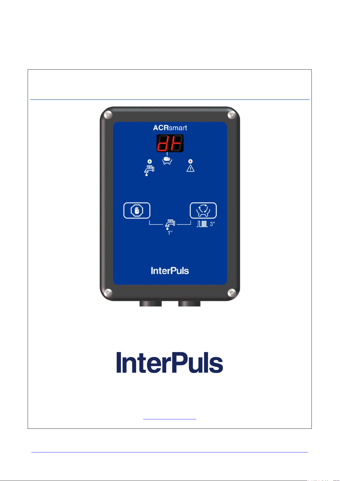
ACR Smart
InterPuls S.p.A.
Via F. Maritano, 11 - 42020 - Albinea (RE) – ITALY
Tel. +39 0522 347511
Fax +39 0522 348516
sales@interpuls.com
Instruction Manual, Operation and Maintenance
original instructions
THIS MANUAL IS THE PROPERTY OF - InterPuls S.p.A. - ANY COPYING, EVEN PARTIAL, IS STRICTLY PROHIBITED

MANUFACTURER
InterPuls S.p.A
ADDRESS
Via: F. Maritano, 11
Postal code 42020 - Albinea (RE) - ITALY
Tel.: +39 0522 347511
Telefax: +39 0522 348516
Website: www.milkrite-interpuls.com
E-mail: sales@interpuls.com
TYPE OF DOCUMENT
Instruction, Use and Maintenance Manual
DOCUMENT CODE
5630006_EN
EDITION
04.17
PRODUCT
Automatic Cluster Removal
MODEL
ACR Smart
YEAR OF MANUFACTURE
2017
InterPuls is a registered trade mark of InterPuls SpA.
The information contained in this document is not binding and can be modified without notice. References in
this document to manufacturer trademarks are for identification only. Certain company and product names
used throughout the document are trademarks of their respective owners.
THIS MANUAL IS THE PROPERTY OF - InterPuls S.p.A. - ANY COPYING, EVEN PARTIAL, IS STRICTLY PROHIBITED
MI - 2

ACR Smart - Instruction Manual, Operation and Maintenance
original instructions
5630006_04.17_EN
Summary
ACR Smart ......................................................................................................................................................... 1
1 GENERAL INFORMATION .................................................................................................................... 5
General information and safety warnings ...................................................................................... 5 1.1
Important warnings .................................................................................................................... 5 1.1.1
Symbol used in this manual ....................................................................................................... 5 1.1.2
Rules and regulations for the user ............................................................................................. 5 1.1.3
Limitation of liability .................................................................................................................... 5 1.1.4
Prior using the product ................................................................................................................... 5 1.2
Requirements and regulations for personnel ............................................................................. 5 1.2.1
Disposal ......................................................................................................................................... 6 1.3
General regulation ..................................................................................................................... 6 1.3.1
Fire prevention ............................................................................................................................... 6 1.4
Fire prevention ........................................................................................................................... 6 1.4.1
Safety regulations ...................................................................................................................... 6 1.4.2
Characteristic of extinguishers................................................................................................... 6 1.4.3
Normative references applied ........................................................................................................ 6 1.5
Marking .......................................................................................................................................... 6 1.6
Dataplates affixed to the machine ............................................................................................. 6 1.6.1
2 DESCRIPTION OF THE DEVICE ........................................................................................................... 7
General features ............................................................................................................................ 7 2.1
Technical characteristics ............................................................................................................... 7 2.2
WIRING DIAGRAM ........................................................................................................................ 8
2.3
General connection diagram ...................................................................................................... 8 2.3.1
Connection diagram for sheep and goat ................................................................................... 9 2.3.2
PCB connection ......................................................................................................................... 9 2.3.3
3 DESCRIPTION OF THE DEVICE ......................................................................................................... 10
Display during operation .............................................................................................................. 11 3.1
4 DESCRIPTION OF THE FUNCTIONS ................................................................................................. 12
Detachment stage (stand-by) ...................................................................................................... 12 4.1
Wash ............................................................................................................................................ 12 4.2
Milking .......................................................................................................................................... 13 4.3
Milking with automatic unit removal ......................................................................................... 13 4.3.1
Manual milking ......................................................................................................................... 14 4.3.2
Indication of milk presence ...................................................................................................... 15 4.3.3
Maximum milking time ............................................................................................................. 15 4.3.4
Detachment operation ................................................................................................................. 15 4.4
Stimulation ................................................................................................................................... 16 4.5
Alarm ............................................................................................................................................ 18 4.6
Quick-Lift ...................................................................................................................................... 18 4.7
Swing-Over .................................................................................................................................. 18 4.8
THIS MANUAL IS THE PROPERTY OF - InterPuls S.p.A. - ANY COPYING, EVEN PARTIAL, IS STRICTLY PROHIBITED
MI - 3

5630006_04.17_EN
ACR Smart - Instruction Manual, Operation and Maintenance
original instructions
5 PROGRAMMING MODE ...................................................................................................................... 19
Accessing the programming mode .............................................................................................. 19 5.1
Programming mode ..................................................................................................................... 19 5.2
Programming parameter table ..................................................................................................... 20 5.3
Parameter reading ....................................................................................................................... 21 5.4
6 GENERAL RECOMMENDATIONS ...................................................................................................... 23
Positioning ................................................................................................................................... 23 6.1
Sensitivity ..................................................................................................................................... 23 6.2
Configurations .............................................................................................................................. 23 6.3
Troubleshooting ........................................................................................................................... 24 6.4
THIS MANUAL IS THE PROPERTY OF - InterPuls S.p.A. - ANY COPYING, EVEN PARTIAL, IS STRICTLY PROHIBITED
MI - 4
ACR Smart - Instruction Manual, Operation and Maintenance
original instructions
5630006_04.17_EN
1 GENERAL INFORMATION
General information and safety warnings 1.1
Important warnings 1.1.1
To safeguard the operator and prevent any damage to the equipment, before carrying out any kind of
operation it is important to have read and fully understood the instruction manual.
Symbol used in this manual 1.1.2
The following symbols are used in this manual to highlight indications and warnings which are of particular
importance:
WARNING:
This symbol indicates health and safety regulations designed to protect operators and/or any
exposed persons.
CAUTION:
This symbol indicates that there is a risk of causing damage to the equipment and/or its
components.
NOTE:
This symbol is used to highlight useful information.
Rules and regulations for the user 1.1.3
WARNING
Any failure to observe the warnings provided in this manual may lead to equipment
malfunctions or damage to the system.
Limitation of liability 1.1.4
InterPuls S.p.A. declines all liability for damage to persons, animals and/or things caused by incorrect use of
the equipment.
Prior using the product 1.2
Requirements and regulations for personnel 1.2.1
ATTENZIONE
Prima di utilizzare il dispositivo, l’operatore è tenuto a leggere attentamente il manuale.
Il dispositivo deve essere utilizzato da persona maggiorenne, istruita, fisicamente e
psichicamente idonea e che abbia ricevuto indicazioni adeguate in merito al funzionamento
dello stesso.
Nel corso del montaggio e dell’attivazione del dispositivo, occorre seguire le istruzioni del
manuale, le norme e i regolamenti concernenti la sicurezza sul luogo di lavoro e la
salvaguardia della salute.
THIS MANUAL IS THE PROPERTY OF - InterPuls S.p.A. - ANY COPYING, EVEN PARTIAL, IS STRICTLY PROHIBITED
MI - 5
5630006_04.17_EN
ACR Smart - Instruction Manual, Operation and Maintenance
original instructions
Disposal 1.3
General regulation 1.3.1
The appliances must be disposed of only and exclusively by specially authorized waste disposal companies
in accordance with all relative legislation and prescriptions.
The packaging must be consigned to the relative authorized companies to be recycled.
Fire prevention 1.4
Fire prevention 1.4.1
NOTE
The machine is not equipped with fire extinguishers.
The operator must make sure that the place in which the appliance is installed is equipped
with an adequate number of suitable fire extinguishers. The extinguishers must be positioned
where they are clearly visible and protected from damage and improper use.
Safety regulations 1.4.2
WARNING
It is strictly prohibited to extinguish fires involving electrical equipment with water!
Characteristic of extinguishers 1.4.3
Use powder, foam or halogen extinguishers which must be positioned next to the device.
Operating personnel must receive adequate instruction on how to use the extinguishers.
Normative references applied 1.5
Europe:
Directive no. 2004/108/EC Electromagnetic Compatibility (EMC)
USA:
FCC Federal Communications Commission
Canada:
IC Industry Canada
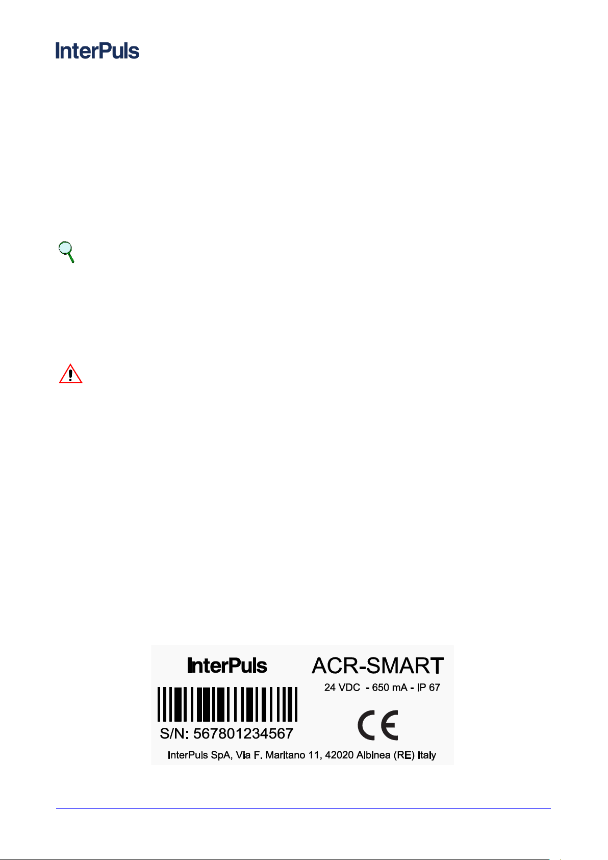
Marking 1.6
Dataplates affixed to the machine 1.6.1
THIS MANUAL IS THE PROPERTY OF - InterPuls S.p.A. - ANY COPYING, EVEN PARTIAL, IS STRICTLY PROHIBITED
MI - 6
ACR Smart - Instruction Manual, Operation and Maintenance
original instructions
5630006_04.17_EN
General technical characteristics
Dimensions
130x180x38 mm (5,12x7,08x1,49 in)
Weight
0.45 kg (0,99 lb)
Power supply
24 VDC
Power consumption of the panel only
100 mA
Power consumption of the system
ACR Smart + CV + LE: 600 mA
Protection rating (cables installed properly)
IP 67
Operating vacuum
between 36 and 60kPa (10,63 and 17,71 “Hg)
typically 50kPa (14,76 “Hg)
Operating temperatures (environment)
-5ºC ÷ +40ºC (23ºF ÷ 104ºF)
Transport/storage temperatures
-20ºC ÷ +50ºC (-4ºF ÷ 122ºF)
2 DESCRIPTION OF THE DEVICE
General features 2.1
The ACR-Smart panel is designed to control all the milking, detachment and washing functions of the unit.
The ACR-Smart is able to control the milking frequency and the pulsation ratio in a wide range of values in
order to meet the needs of all systems (both in the high line and low line) and of all types of animals (cattle sheep - goats).
The ACR-Smart is able to perform a stimulation that can be forced, automatic (dependent on the flow of milk)
or manual (activated directly by the milker at any time).
The panel is compatible with swing-over systems in which the unit is detached by moving the arm. In fact,
with the ACR-Smart you can control the pneumatic cylinder responsible for moving the unit from the right
hand row to the left hand row and vice versa.
It is suitable for milk transport systems thanks to the alarm indicating the end of the milking process and the
possibility to restart the panel from the last active stage.
The ACR-Smart can be connected to remote start-up devices (AutoStart) and remote stop devices (Quick Lift
Line).
Technical characteristics 2.2
THIS MANUAL IS THE PROPERTY OF - InterPuls S.p.A. - ANY COPYING, EVEN PARTIAL, IS STRICTLY PROHIBITED
MI - 7
5630006_04.17_EN
ACR Smart - Instruction Manual, Operation and Maintenance
original instructions
Terminal
Colour
Electrical connection
1
Red
24VDC (+)
2 Blue
24VDC (-)
3
Blue
Flashing light 24VDC(+)
4 Black
Flashing light 24VDC (-)
5
Remote start-up key (AutoStart)
6 7
“Quick-Lift” key
8 9
Grey
“Rear” LE pulsation
Brown
10
White
LE “Common”
Black
11
Yellow
“Front” LE pulsation
Blue
12
Green
CV (to valve)
Blue
13
Pink
CV “Common”
Black
14
Brown
CV (to cylinder)
Brown
15
HFS sensor
16
END OF MILKING
SESSION FLASHING
LIGHT
TO THE NEXT PANEL
LE
IUP
DVC AS
MILK LINE
VACUUM
LINE
ACR
SMART
HFS EVO
24VDC+
24VDC -
QUICK-LIFT
KEY
CV
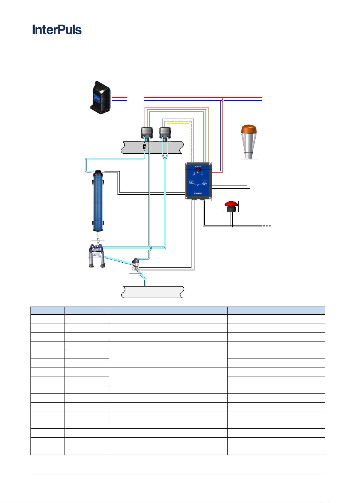
WIRING DIAGRAM 2.3
General connection diagram 2.3.1
THIS MANUAL IS THE PROPERTY OF - InterPuls S.p.A. - ANY COPYING, EVEN PARTIAL, IS STRICTLY PROHIBITED
MI - 8

ACR Smart - Instruction Manual, Operation and Maintenance
original instructions
5630006_04.17_EN
END OF MILKING
SESSION FLASHING
LIGHT
TO THE NEXT PANEL
LE
IUP
DVC AS
MILK LINE
VACUUM
LINE
ACR
SMART
HFS
24VDC+
24VDC -
QUICK-LIFT KEY
CV
HFS
(S/O Valve)
Quick Lift Line
DVC
(with Autostart)
LAMPADA
(end of milking)
- 24 VDC
+ 24 VDC
BLUE
RED
-24VDC
BLACK
BLUE
+24VDC
Brown
Pink
Green
Yellow
White
Grey
C
Common
Front
Common
Rear
CV
(Control Valve)
LE30
(Pulsator)
Brown
Black
Blue
Blue
Black
Brown
Connection diagram for sheep and goat 2.3.2
PCB connection 2.3.3
THIS MANUAL IS THE PROPERTY OF - InterPuls S.p.A. - ANY COPYING, EVEN PARTIAL, IS STRICTLY PROHIBITED
MI - 9

5630006_04.17_EN
ACR Smart - Instruction Manual, Operation and Maintenance
original instructions
A
E
B
D
C
3 DESCRIPTION OF THE DEVICE
A) Display
B) LEDs (green LED, red LED)
C) Stop key
D) Milking process start button with automatic detachment, continuous pressure for 3”, stimulation start
E) Combination of keys for accessing the washing or programming mode
THIS MANUAL IS THE PROPERTY OF - InterPuls S.p.A. - ANY COPYING, EVEN PARTIAL, IS STRICTLY PROHIBITED
MI - 10

ACR Smart - Instruction Manual, Operation and Maintenance
original instructions
5630006_04.17_EN
Display
Indication
Meaning
Code St
Stimulation in progress
Code CL
Panel in washing mode
Left digit: the first segment at the top indicates
the initial delay count
Right digit: milking time
Initial delay without continuous flow
Left digit: when all the horizontal segments
are lit-up, it means that there is continuous
flow during the initial delay
Right digit: milking time
Initial delay with continuous flow
Left digit: when the central segment lights up
it means that there is continuous milk flow
Right digit: milking time
Milking with continuous flow
Right digit: milking time
Left digit: only the bottom segment lit-up
indicates the final delay count
- Milking without continuous flow (final
delay count)
- Detachment operations
The central point flashing indicates manual
milking
- Manual milking
Code dt
Detachment
Code AL (flashing)
Milking without continuous flow alarm
Display during operation 3.1
THIS MANUAL IS THE PROPERTY OF - InterPuls S.p.A. - ANY COPYING, EVEN PARTIAL, IS STRICTLY PROHIBITED
MI - 11

5630006_04.17_EN
ACR Smart - Instruction Manual, Operation and Maintenance
original instructions
Key
Function
Start automatic milking
Removal or release of the milking unit
+
Start washing
+ x 5”
Access programming mode
QUICK-LIFT operation
Removal or release of the milking unit
AUTO-START operation
Start automatic milking via remote control (cylinder with AS or remote
button)
4 DESCRIPTION OF THE FUNCTIONS
Upon start-up the panel display indicates the software version installed. Depending on the configured
parameters, the panel may then restart during:
washing
detachment (default)
last active stage
Detachment stage (stand-by) 4.1
The display features the code dt (Detachment) with the green LED switched on. During this stage the panel
waits for the commands from the operator.
The S/O valve therefore stays closed, while the unit may switch from the release position to the removal
position or vice versa via the key or via the Quick Lift control
Wash 4.2
The wash function may be operated
manually, when the system is in the detachment position, by pressing the two + keys
instantaneously
automatically if pre-set as a start-up function on the programming menu (parameter I.P. set on L.p.).
The display features the code CL and the green LED starts flashing. The unit is released and the count
relating to the shut-off closure delay starts (parameter c.S.). When it has elapsed, the valve is opened and
the washing stage starts.
You can set a different frequency during the washing cycle (parameter U.F.).
Press the key to stop the washing cycle and retract the unit.
THIS MANUAL IS THE PROPERTY OF - InterPuls S.p.A. - ANY COPYING, EVEN PARTIAL, IS STRICTLY PROHIBITED
MI - 12

ACR Smart - Instruction Manual, Operation and Maintenance
original instructions
5630006_04.17_EN
The upper line indicates the initial delay count
The central line switched off indicates the
absence of milk
The upper line indicates the initial delay count
The central line indicates the presence of milk
CAUTION
At the end of washing phase it’s recommended to power off the ACRSmart panels to avoid
that the coils of control valves stay powered for long time and being damaged. Upon start-up,
the panel may restart in washing phase or detachment phase according to the parameter I.p.
WARNING
Do not press the key and do not press the quick-lift switch during the washing cycle:
the unit would be removed from the washing plate.
Milking 4.3
Milking with automatic unit removal 4.3.1
To start the milking process with automatic detachment press the key during the detachment stage
or operate the Auto-Start contact.
NOTE
Terminals 11-12 may be used to connect a REMOTE KEY or an AUTO-START device to start
the milking process without having to press the key on the panel
When the automatic milking process starts:
the cylinder releases the unit.
after the vacuum/pulsation delay (parameter P.d.), the pulsator is activated and the valve (shut-off)
of the flow sensor is opened.
The display then starts counting the milking time. The upper horizontal segment indicates the initial delay
count (parameter I.d.). At the same time, the two vertical segments indicate the opening of the pulsator
channels, flashing alternately.
When the milk presence signal constantly exceeds the value defined by the position of the jumpers, the
panel detects a continuous flow and the horizontal segment of the left hand display lights up.
When the initial delay has elapsed (parameter I.d.), the upper horizontal segment switches off.
When there is no longer any milk flow, the central segment switches off and the final delay count starts
(parameter F.d.). The detachment operations start when the delay has elapsed.
THIS MANUAL IS THE PROPERTY OF - InterPuls S.p.A. - ANY COPYING, EVEN PARTIAL, IS STRICTLY PROHIBITED
MI - 13

5630006_04.17_EN
ACR Smart - Instruction Manual, Operation and Maintenance
original instructions
The upper line switched off indicates the end
of the initial delay
The central line indicates the presence of milk
The sole lower line indicates the absence of
milk and therefore the final delay count
In each milking stage, the two vertical lines
flash following the frequency of the pulsator
During all milking stages, press the key to switch from automatic milking to manual milking and vice
versa.
Throughout milking, the right hand display indicates the duration of the milking process in minutes. The lit-up
dot indicates that milking has exceeded 10 minutes.
>> 15 minutes
Press the key (or activate the quick-lift button) to immediately stop the milking operations and start
the detachment operations.
Manual milking 4.3.2
To start milking with manual unit removal, press the key after the system has been started in
automatic milking mode:
The dot flashing in the left hand digit of the display indicates Manual Milking.
Manual milking LED
The panel stays in the manual milking mode as long as:
the button is pressed to switch to the automatic milking mode
or the button is pressed to start the detachment operations
Press the key to switch from the manual milking mode to the automatic milking mode and vice versa,
at any time.
THIS MANUAL IS THE PROPERTY OF - InterPuls S.p.A. - ANY COPYING, EVEN PARTIAL, IS STRICTLY PROHIBITED
MI - 14

ACR Smart - Instruction Manual, Operation and Maintenance
original instructions
5630006_04.17_EN
Indication of milk presence 4.3.3
During milking, the left hand display indicates the current milking stage and the presence/absence of milk.
The central horizontal segment indicates if milk is going through the sensor at that time. If the milk presence
signal lasts for a period equal to the continuous flow time (parameter c.F.), the panel detects that there is an
actual continuous flow.
Maximum milking time 4.3.4
WARNING
You can envisage a maximum milking time, which can be set or disabled in the programming
menu (parameter E.t.)
If this limit is reached, the unit detachment operations start automatically and, in the event of
no flow during the milking process, the anomaly is signalled via an alarm
Detachment operation 4.4
When the initial delay has elapsed, if the panel does not detect a continuous flow of milk, the final delay
count starts (parameter F.d.).
If the continuous flow of milk is resumed, the delay is reset. The unit removal operations start when the final
delay has elapsed.
The removal procedure can also be started manually by pressing the key
The pulsator stops
the S/O Valve closes the vacuum passage
the detachment delay time count starts (parameter d.d.), in order to wait for a certain amount of air
to leak through the collection unit hole, lowering the vacuum level under the nipples before removing
the unit
when the delay has elapsed, the cylinder gently removes the unit
if the suction function has been activated (parameter S.L.) , when the suction delay time has elapsed
(parameter S.d.) the residue milk in the collection unit and in the milk pipe is aspirated through the
flow meter
if the automatic unit release function has been activated, when the automatic release delay has
elapsed (parameter A.r.) the unit is released automatically to start a new milking session.
During the detachment stage the green LED flashes and the display features:
- the milking time in the right hand digit
- the sole lower segment in the left hand digit
Absence of continuous flow
and indication of milking time
After the detachment operation the green LED stays fixed on and the display features .
At the end of the milking operations, the pair of terminals 3-4 is powered at 24VDC; the pair of terminals can
be connected to a flashing light for indicating the end of milking.
Press the key to switch off the flashing light and switch to the actual detachment condition (standby); press the key to start a new milking session.
THIS MANUAL IS THE PROPERTY OF - InterPuls S.p.A. - ANY COPYING, EVEN PARTIAL, IS STRICTLY PROHIBITED
MI - 15

5630006_04.17_EN
ACR Smart - Instruction Manual, Operation and Maintenance
original instructions
Stimulation 4.5
During the stimulation stage, the display features the code St and the LEDs start flashing.
On the programming menu you can define the type of stimulation (parameter t.S.) which may be:
Forced (F.S.)
Automatic (A.S.)
OFF (oF) – can only be activated manually
FORCED STIMULATION
During programming you can set a forced stimulation cycle at the beginning of each milking process.
For a certain period of time (“stimulation time”, which can be set via parameter S.t.) the frequency
and pulsation ratio are gradually modified in order to reach the set values (stimulation frequency
S.F., stimulation ratio S.r.)
AUTOMATIC STIMULATION
Stimulation starts if the function is enabled and if during milking the s/o valve does not detect a
“Continuous Flow” for a certain period of time (called “neutral time”, which can be set via parameter
n.t.).
Therefore the frequency and pulsation ratio vary gradually until reaching the values set for
stimulation (stimulation frequency S.F., stimulation ratio S.r.)
Stimulation stops when the flow meter starts detecting a “Continuous Flow” again or when the
stimulation time elapses (parameter S.t.)
MANUAL STIMULATION
Press and hold the key for 3” during the milking cycle (with any value set for parameter t.S.)
to start the manual stimulation process: the frequency and pulsation ratio vary gradually until
reaching the values set for stimulation (stimulation frequency S.F., stimulation ratio S.r.). Stimulation
stops when the stimulation time has elapsed (parameter S.t.) and the frequency and pulsation ratio
gradually go back to the values set for milking.
NOTE
By setting stimulation ratio (parameter S.r.) on value 0, upon start of the stimulation, the
liners stay completely closed and the pulsation stops until the end of stimulation time (S.t.).
THIS MANUAL IS THE PROPERTY OF - InterPuls S.p.A. - ANY COPYING, EVEN PARTIAL, IS STRICTLY PROHIBITED
MI - 16

ACR Smart - Instruction Manual, Operation and Maintenance
original instructions
5630006_04.17_EN
Litres/minute
Initial
Delay
Final
Delay
Final
Delay
Final
Delay
Detachment
Operations
Time
Start of milking session
When the Pulsation delay
has elapsed, the pulsator is
activated
The Initial delay count
starts
When the Initital Delay has
elapsed, the sensor starts
monitoring a Continuous
Flow of milk
If a Continuous Flow of
milk is detected, the
milking process continues
normally
If a Continuous Flow of milk
is not detected, the Final
Delay count starts
If a Continuous Flow of milk
is detected before the Final
Delay has elapsed, the
milking process continues
normally
If a Continuous Flow of milk
is not detected, before the
Final Delay has elapsed, the
Detachment Operations
start and the operator is
warned by the warning LED
and display flashing. Now,
press the STOP button to
delete the milking alarm
As soon as there is no
Continuous Flow of milk, the
Final Delay count starts
As soon as a Continuous
Flow signal is detected
again, the milking process
continues normally
If a Continuous Flow is not
detected, the Detachment
Operations start
THIS MANUAL IS THE PROPERTY OF - InterPuls S.p.A. - ANY COPYING, EVEN PARTIAL, IS STRICTLY PROHIBITED
MI - 17

5630006_04.17_EN
ACR Smart - Instruction Manual, Operation and Maintenance
original instructions
Alarm 4.6
If a continuous flow is not detected during the milking process, when the initial delay has elapsed and during
the subsequent final delay time count, code AL and the red LED start flashing on the display.
The unit removal procedures start automatically, after which code AL still appears alternately with code dt on
the display, and the red LED keeps flashing.
Press the key to reset the alarm and switch to the detachment mode (stand-by).
Quick-Lift 4.7
The quick-lift button corresponds to pressing the key on the panel
If terminals 7-8 on all the panels are connected to an external switch, by pressing this key you can lift or
release all the units at the same time. This way, at the beginning of the milking process, you can release all
the units at the same time.
Swing-Over 4.8
By activating the Swing-Over mode (Type of System dt = S.O. parameter) the ACR-Smart panel can
manage systems in which the unit is detached via a pneumatic piston that moves the Swing-Over arm from
one side to the other.
By connecting this piston to the CV output, normally dedicated to the DVC, and setting the ACR-Smart Type
of System parameter, at the end of the milking process the panel will automatically move the arm in order to
start milking again on the other side.
Therefore, via the button or via the remote Quick-Lift switch, you can move arms from one side of
the milking parlour to the other.
THIS MANUAL IS THE PROPERTY OF - InterPuls S.p.A. - ANY COPYING, EVEN PARTIAL, IS STRICTLY PROHIBITED
MI - 18

ACR Smart - Instruction Manual, Operation and Maintenance
original instructions
5630006_04.17_EN
5 PROGRAMMING MODE
Accessing the programming mode 5.1
To access the Programming menu, press the + key for 10” while the system is in
detachment mode.
The display features the first parameter identified by its code and the LEDs start flashing alternately.
Programming mode 5.2
In the programming menu you can edit the values associated to the parameters in order to optimise the
milking, stimulation, detachment and washing operations.
The display features the code of the selected parameter.
Press the or keys to scroll the available parameters, each identified by its code.
Press the + keys to access the parameter and modify it. The current value of the selected
parameter is displayed.
Press the or keys to scroll the parameter values.
Press the + keys to confirm the value assigned to the parameter and go back to the previous
menu. If the parameter has been modified, the display flashes.
To exit the programming mode press and hold the + keys for 5”; the panel is then
automatically restarted and the version of the software currently installed in displayed.
THIS MANUAL IS THE PROPERTY OF - InterPuls S.p.A. - ANY COPYING, EVEN PARTIAL, IS STRICTLY PROHIBITED
MI - 19

5630006_04.17_EN
ACR Smart - Instruction Manual, Operation and Maintenance
original instructions
Parameter
name
Code
Description
Range
Unit of
measure
Default
SHUT-OFF
SOLENOID VALVE
ES
Select the type of solenoid valve used for
shut-off, NO - normally open (vac channel)
or NC - normally closed (atm channel)
N.O. – N.C.
//
N.O.
CYLIDER
SOLENOID VALVE
EC
Select the type of solenoid valve used for
DVC, NO - normally open (vac channel) or NC
- normally closed (atm channel)
N.O. – N.C.
//
N.O.
INITIAL DELAY
Id
Time at the beginning of the milking process
in which milk presence is not checked
0÷19
(corresponds to
0÷190)
Seconds (10x)
8 (= 80
seconds)
FINAL DELAY
Fd
If the panel does not detect a continuous
flow of milk throughout the entire delay, it
starts the detachment operations
0÷30
Seconds
9
DETACHMENT
DELAY
dd
At the end of the milking process, it is the
delay between the closure of the s/o valve
and the unit removal
0÷9
Seconds
3
AUTOMATIC
RELEASE DELAY
Ar
When the delay has elapsed, after
detachment, the unit is released
of - 5 - 15 - 30 -
45 - 60
Seconds
of
CONTINUOUS
FLOW TIME
cF
If the sensor detects the presence of milk for
a period equal to the continuous flow time,
then there is an actual flow of milk
0÷4.0
Seconds
1
PULSATION
FREQUENCY
Fr
Pulsation frequency during the milking
process
50÷180
LP
Ppm
60
REAR PULSATION
RATIO
Pr
Pulsation ratio of the hindquarters during
the milking process
10:90 ÷ 90:10
Pulsation ratio
60 (= 60:40)
FRONT
PULSATION
RATIO
PF
Pulsation ratio of the forequarters during
the milking process
10:90 ÷ 90:10
Pulsation ratio
60 (= 60:40)
START-UP STAGE
Ip
Select in which stage the panel must start
- dt: start in detachment mode
- CL: start in washing mode
- LP: start from the last active stage
dt - CL - LP
//
CL
FINAL SUCTION
DELAY
Sd
Delay between the end of the milking
session and the opening of the s/o valve for
suction
0÷9
Seconds
3
FINAL SUCTION
DELAY
SL
During opening of the s/o valve to drain the
pipe completely at the end of the milking
session
0f ÷ 9
Seconds
of
STIMULATION
FREQUENCY
SF
Pulsation frequency during the stimulation
stage
3÷25
(corresponding
to 30÷250)
Ppm
12 (=
120ppm)
STIMULATION
TIME
St
Duration of stimulation
10÷90
Seconds
20
STIMULATION
RATIO
Sr
Pulsation ratio during stimulation
0:100 ÷ 100:0
Pulsation ratio
30 (= 30:70)
NEUTRAL TIME
nt
When this time has elapsed, if there has not
been a continuous flow of milk, automatic
stimulation starts if it has been set
0÷24
(corresponding
to 0÷240)
Seconds (10x)
2 (=20
seconds)
Programming parameter table 5.3
THIS MANUAL IS THE PROPERTY OF - InterPuls S.p.A. - ANY COPYING, EVEN PARTIAL, IS STRICTLY PROHIBITED
MI - 20

ACR Smart - Instruction Manual, Operation and Maintenance
original instructions
5630006_04.17_EN
TYPE OF
STIMULATION
tS
Selection of type of stimulation
- FS: forced stimulation
- AS: automatic stimulation
- oF: stimulation that can only be
activated manually
FS - AS - oF
//
AS
PULSATION
DELAY
Pd
Delay between the beginning of the milking
process and the pulsation starting
0÷9
Seconds
0
FREQUENCY IN
WASHING MODE
UF
Pulsation frequency during the washing
cycle
0÷15
(corresponding
to 0÷150)
ppm
2 (= 20ppm)
MAXIMUM
MILKING
TIME
Et
The detachment operations always start
when this time has elapsed
10 - 15 - 20
Minutes
20
SHUT OFF
CLOSURE DELAY
cS
Before starting the washing cycle, the s/o
valve stays closed throughout the delay
period, in order for the system to create
vacuum
Of ÷ 90
Seconds
of
TYPE OF SYSTEM
dt
Definition of the type of system in which the
panel is used:
CY: Standard system
SO: Swing-Over
CY - S0
//
CY
Parameter reading 5.4
Shut-Off Solenoid Valve – E.S. and Cylinder Solenoid Valve– E.C.:
- With CV30 inversa set:
o E.S. = N.C. (atm channel)
o E.C. = N.O. (vac channel)
- With CV30 set:
o E.S. = N.C.
o E.C. = N.C.
- With CV20 set:
o E.S. = N.O.
o E.C. = N.O.
Start-up stage – IP :
- dt upon start-up the panel retracts the unit and goes into detachment mode (stand-by)
- CL upon start-up the panel releases the unit and goes into washing mode
- LP upon start-up the panel starts from the last active stage (if it is switched off during the milking
cycle it will restart in detachment mode)
Initial delay – Id :
- 10 second steps
- The parameter values must be multiplied by 10 (the dot lit-up indicates the x10 multiplication)
>> 120 seconds
Pulsation frequency in milking mode – Fr :
- LP indicates that the panel is not controlling pulsation and that it is only powering the pulsator
- The dot lit-up indicates that the value must be added to 100
>> 115ppm
THIS MANUAL IS THE PROPERTY OF - InterPuls S.p.A. - ANY COPYING, EVEN PARTIAL, IS STRICTLY PROHIBITED
MI - 21

5630006_04.17_EN
ACR Smart - Instruction Manual, Operation and Maintenance
original instructions
Pulsation frequency in stimulation mode – SF :
- The dot lit-up indicates that the value must be multiplied by 10
>> 150ppm
Neutral time – nt :
- The dot lit-up indicates that the value must be multiplied by 10
>> 80 seconds
Stimulation time – tS :
- FS forced stimulation
- AS automatic stimulation
- Of no stimulation
NOTE
It is always possible to activate manual stimulation with any value set in parameter tS.
Type of system – dt :
- CY system with cylinder-operated detachment
- SO system with detachment via movement of the Swing-Over arm (the CV channel controls a
piston that moves the arm from right to left and vice versa)
THIS MANUAL IS THE PROPERTY OF - InterPuls S.p.A. - ANY COPYING, EVEN PARTIAL, IS STRICTLY PROHIBITED
MI - 22

ACR Smart - Instruction Manual, Operation and Maintenance
original instructions
5630006_04.17_EN
Milk Flow
OHM
Volt
ACR Jumpers
> 500 gr/min
700
6.10 +/- 0.07
JUMPER 1 CLOSED
JUMPER 2 CLOSED
300 gr/min
1270
6.20 +/- 0.07
JUMPER 1 OPEN
JUMPER 2 CLOSED
100 gr/min
2000
6.32 +/- 0.07
JUMPER 1 CLOSED
JUMPER 2 OPEN
< 100 gr/min
2660
6.42 +/- 0.07
JUMPER 1 OPEN
JUMPER 2 OPEN
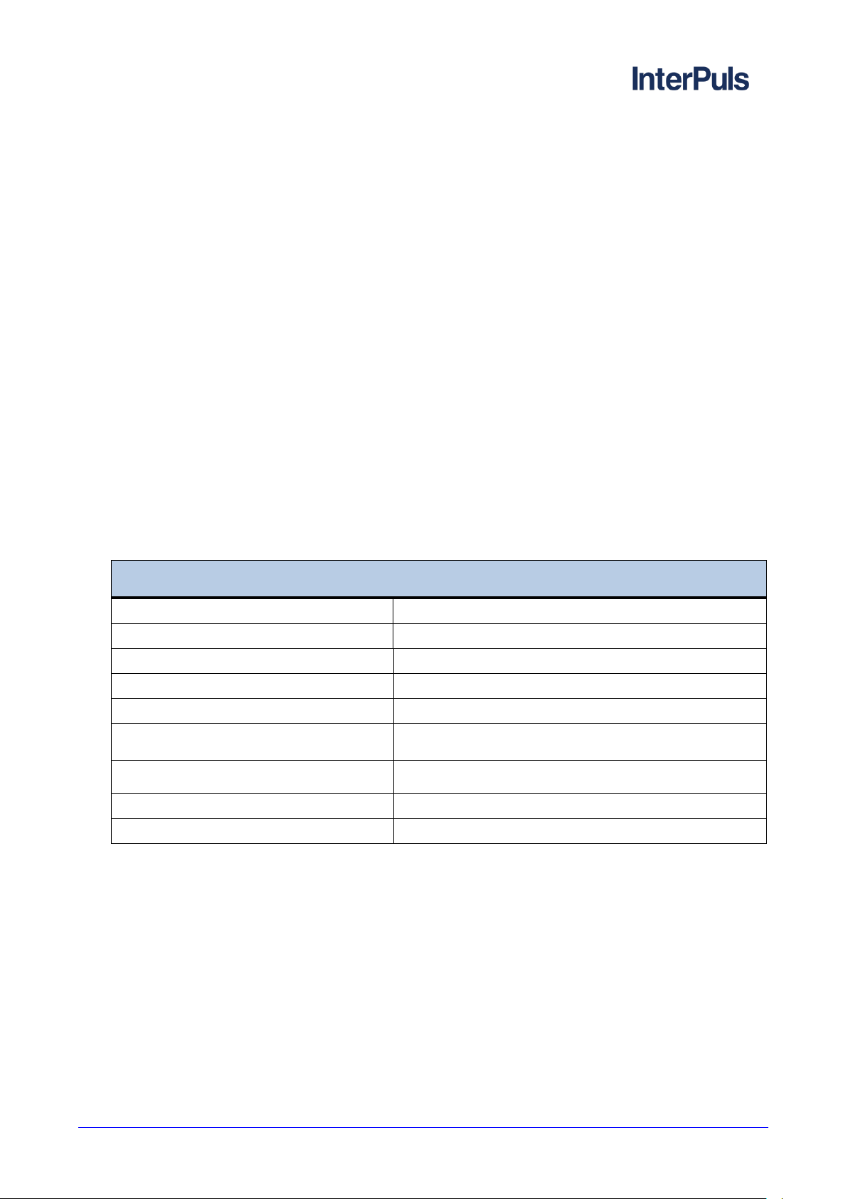
Type of system
Recommended settings
High Line
Decrease the Continuous Flow c.F. parameter = 0.3 seconds
Low Line
Decrease the Final Delay F.d. parameter = 6 seconds
Goats or sheep
Decrease the Continuous Flow c.F. parameter = 0.2 seconds
Decrease the Final Delay F.d. parameter = 8 seconds
If the system continues to detach too soon, open both jumpers
JUMPER 2 - OPEN
JUMPER 1 - CLOSED
6 GENERAL RECOMMENDATIONS
Positioning 6.1
Make sure that the HFS sensor is in a vertical position.
Sensitivity 6.2
The ACR panel is designed to detect milk flows below the 100 gr/min limit (preferably with the HFS sensor).
It is possible (but NOT recommended) to increase or decrease this threshold via the jumpers on the board.
Configurations 6.3
THIS MANUAL IS THE PROPERTY OF - InterPuls S.p.A. - ANY COPYING, EVEN PARTIAL, IS STRICTLY PROHIBITED
MI - 23

5630006_04.17_EN
ACR Smart - Instruction Manual, Operation and Maintenance
original instructions
Problem
Causa
Solution
The unit is detached too soon
Incorrect setting of Final Delay
and/or Continuous Flow
parameters
Increase the F.d. (Final Delay)
parameter and/or decrease the
c.F. (Continuous Flow)
parameter
The unit is detached too late
Incorrect setting of Final Delay
and/or Continuous Flow
parameters
Decrease the F.d. (Final Delay)
parameter and/or increase the
c.F. (Continuous Flow)
parameter
The shut-off valve stays closed
during milking and during washing
Incorrect setting of Shut-Off
Solenoid parameter
Check that the parameter E.S. is
set on N.O. if is used a VAC
channel (eg. CV20) or on N.C. if
is used an ATM channel (eg.
CV30)
Troubleshooting 6.4
THIS MANUAL IS THE PROPERTY OF - InterPuls S.p.A. - ANY COPYING, EVEN PARTIAL, IS STRICTLY PROHIBITED
MI - 24
 Loading...