

Page 1

F3XT
INSTRUCTION MANUAL
www.interphone.cellularline.com
Page 2
A
X
B
6
2
4
8
13
X
11
14
C
Y
13
B
X
A
1
3
5
7
10
full-face open-face flip-up
Y
12
15
16
8
2
9
Page 3
9
1
7
5
6
8
4
3
2
F4XT
8
B
B
A
A
B
B
A
A
A
B C
A
A
B
B
B
A
B
10
A - YELLOW
B - GREEN
1 - MFB (multifunction button)
2 - UP button
3 - DOWN button
4 - + volume button
5 - – volume button
7 - Multifunction LED
7 - Multifunction LED
8 - Multifunction audio/data port
9 - Mounting guides for Bluetooth® module
10 - Charging/audio-in connector
* see the user manual
for complete instructions.
ASSEMBLY OF THE SLIDE SUPPORT
WITH REMOVABLE CLIP
Take the support and note the best place
to fasten it to the side of the helmet. Insert
the rear part of the clip into the helmet and
attach the other part on the outside.
ASSEMBLY OF THE ADHESIVE SLIDE
SUPPORT
Take the adhesive support and look for the
best side and place to position it. Clean and
de-grease the part of the helmet where you
are going to stick the support (do not use
any detergents that could damage the hel-
Insert the screws and
tighten gently. Check
position and move the
support if necessary by sli-
ding it along. Tighten the
screws with the screwdri-
ver supplied.
(images A/B)
met’s finish). Remove the
protective film from the
double sided tape, and
apply the support to the
helmet.
As the support cannot be
moved once it is attached
to the helmet, take great
care with its positioning
when applying.
(image C)
MOUNTING ON
FULL-FACE HELMET
MOUNTING ON
MODULAR HELMET
MOUNTING ON
OPEN FACE HELMET
MOUNTING ON
FULL-FACE HELMET
MOUNTING ON
MODULAR AND
OPEN-FACE
HELMETs
PHASE 1
PHASE 1
PHASE 3
PHASE 2
PHASE 4
PHASE 3 PHASE 4
PHASE 2
F3XT
QUICK GUIDE
L
EN
F
WE RECOMMEND YOU CHECK FOR
SOFTWARE UPDATES ON THE WEBSITE
WWW.INTERPHONE.CELLULARLINE.COM
E
www.interphone.cellularline.com
M
x 4
I
D
x 2
4
G
J
K
Page 4
IT
IT
EN
Manuale di istruzioni
IT
IT
Instruction manual
EN
EN
Mode d’emploi
FR
FR
x
y
y
y
6
y
x
x
x
Manual operativo
ES
ES
Bedienungsanleitungen
DE
DE
Návod k použití
CS
CS
Handleiding
NL
NL
Руководство по эксплуатации
RU
RU
Instrukcja obsługi
PL
PL
Bruksanvisning
SV
SV
Käyttöohje
FI
FI
Manual do utilizador
PT
PT
取扱説明書
JP
JP
EN
FR
FR
ES
ES
DE
DE
CS
CS
NL
NL
RU
RU
PL
PL
SV
SV
FI
FI
PT
PT
JP
JP
Page 5
IT
IT
EN
TABLE OF CONTENTS
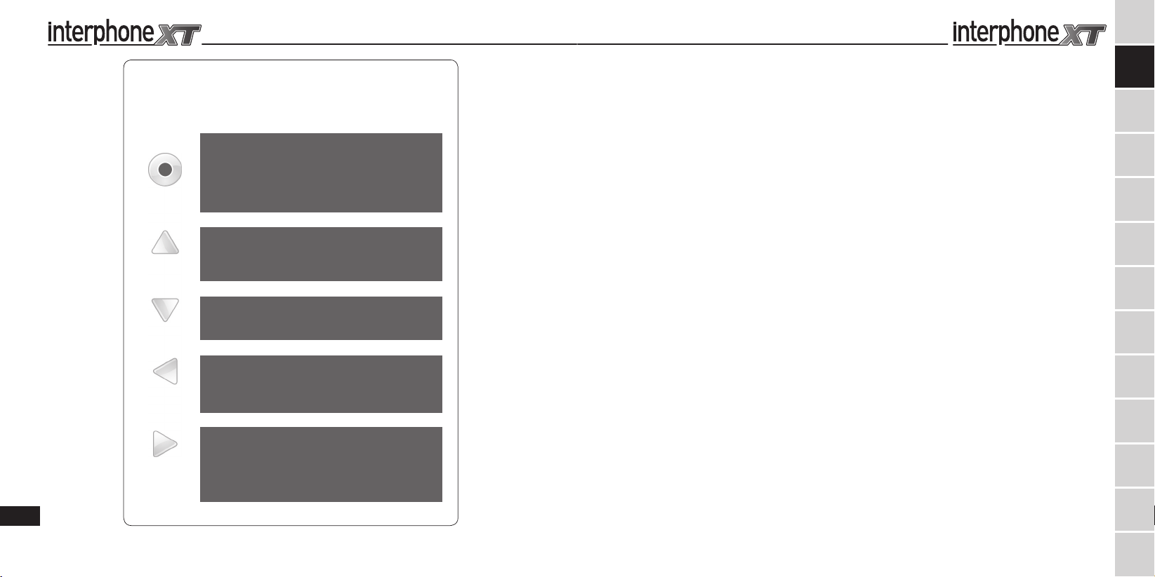
F4XT - F3XT BUTTON DIAGRAM
MFB BUTTON
ON press for 3 seconds
OFF - press for 5 seconds
INTERCOM/ON - press briefly
INTERCOM/OFF - press briefly
MFB
UP
DOWN
VOL. +
VOL. –
8
VOICE CALL/ON - hold down until you hear the beep (3 seconds)
VOICE CALL/OFF - hold down until you hear the beep (3 seconds)
UP BUTTON
MUSIC/PLAY hold down until you hear the beep (3 seconds)
MUSIC/PAUSE hold down until you hear the beep (3 seconds)
NEXT SONG press briefly
DOWN BUTTON
BEGIN SONG press once
NEXT SONG press once or twice
+ VOLUME BUTTON
INCREASE VOLUME press multiple times
ENABLE VOICE RESPONSE: hold down until you hear the beep (9 seconds)
VOLUME BUTTON
REDUCE VOLUME press multiple times
MUTE/ON - hold down until you hear the beep (3 seconds)
MUTE/OFF - press briefly
DISABLE VOICE RESPONSE: hold down until you hear the beep (9 seconds)
PRESENTATION .......................................10
FUNCTIONS. . . . . . . . . . . . . . . . . . . . . . . . . . . . . . . . . . . . . . . . . . . .10
CHARACTERISTICS ....................................10
NOTES ON AUTONOMY ...............................11
CONTENTS OF THE PACKAGE .........................11
PRODUCT DESCRIPTION ..............................11
CARE AND MAINTENANCE ............................11
1.0 PREPARATION/ASSEMBLY ........................12
1.1 Mounting the bracket on the helmet .............12
1.2 Audio section ...................................12
1.3 Charging ........................................13
1.4 Turning on/off ...................................13
2.0 PAIRING ...........................................13
2.1 Telephone. . . . . . . . . . . . . . . . . . . . . . . . . . . . . . . . . . . . . . . . . . . . . 13
2.2 Intercom ........................................14
2.3 Audio GPS ......................................14
3.0 USE. ...............................................14
3.1 Telephone function ..............................14
3.2 Intercom function ...............................14
3.3 Telephone + Intercom function ..................14
3.4 Voice response (VOX ) ...........................14
3.5 Voice call ........................................14
3.6 Bluetooth® Music ................................14
EN
FR
FR
ES
ES
DE
DE
CS
CS
NL
NL
RU
RU
PL
PL
SV
SV
FI
FI
PT
PT
JP
JP
Page 6
IT
IT12IT
INTERPHONE F3XT is a Bluetooth® helmet system for entertainment and information while driving a motorcycle.
INTERPHONE F3XT is compatible with all mobile phones
and GPS navigators with Bluetooth® technology.
The module is covered by a special Weather Protection Skin
membrane making it fully waterproof. Its aerodynamics have
been designed to avoid any disturbances generated by air
turbulence, and to allow water, if raining, to slide away.
Its controls and shape have been designed to allow for quick
and easy identification and access while riding wearing
gloves.
INSTALLATION
INTERPHONE F3XT can be installed on any helmet, without
affecting its structure or finish. Once installed, it can be removed at any time. INTERPHONE F3XT does not change the
helmet’s certification.
WHILE DRIVING
Always give priority to driving your vehicle, not to telephone
calls.
During a telephone conversation, or while using the intercom,
reduce your speed and concentrate on your driving.
In bad weather and/or heavy traffic, we recommend pulling
over and stopping before answering.
Always ride carefully and in accordance with the current highway code.
WHEN STOPPED
To avoid theft, if leaving the helmet on the motorcycle, INTERPHONE F3XT is fitted with a quick release button to al-
low you to remove the external Bluetooth® module and take
it with you.
10
FUNCTIONS
Telephone functions
• Voice response
• Voice call
• Use of independent telephone on both units
Intercom Functions
• Driver-passenger connection
• Intercom communication with activation button
• Phone call notication
GPS functions
• Bluetooth® GPS audio instructions
• Phone call notication
Stereo functions
• Wireless hi- stereo connection with mobile phones and
Bluetooth® A2DP MP3 players
• Music control using InterphoneF3XT buttons
• Automatic resumption of the song from the exact point
when temporarily interrupted
• Phone call notication
CHARACTERISTICS
• Full duplex communication
• DSP lter
(digital cancellation of wind and background noise)
• Automatic volume adjustment
(speed and noise compensation)
• Fully waterproof (IP67)
• Installation in just 5 minutes
• Removable control panel
• Lithium battery
• Active use autonomy: up to 12 hours
(Considering that the average use time, alternating the vari-
ous functions, is shorter)
• Standby duration: up to 700 hours
• Recharge time 3 hours
• Weight: 83g including ear phones and microphone
NOTES ON AUTONOMY
Active use autonomy is indicative. It has been calculated by
alternating the use of all the INTERPHONE F3XT functions
and, given the varied use of these; it can vary significantly
from one use to another.
During Intercom communication, one of the two Interphone
or INTERPHONE F3XT devices has greater battery consumption: this phenomenon is due to the wireless search procedure the one of the control units performs to remain connected to the other and can also lead to 60/90 minute autonomy
difference.
On long journeys, to optimise battery duration, we advise enabling Intercom mode only when you wish to communicate,
remaining in stand-by or an alternative mode when not actually communicating.
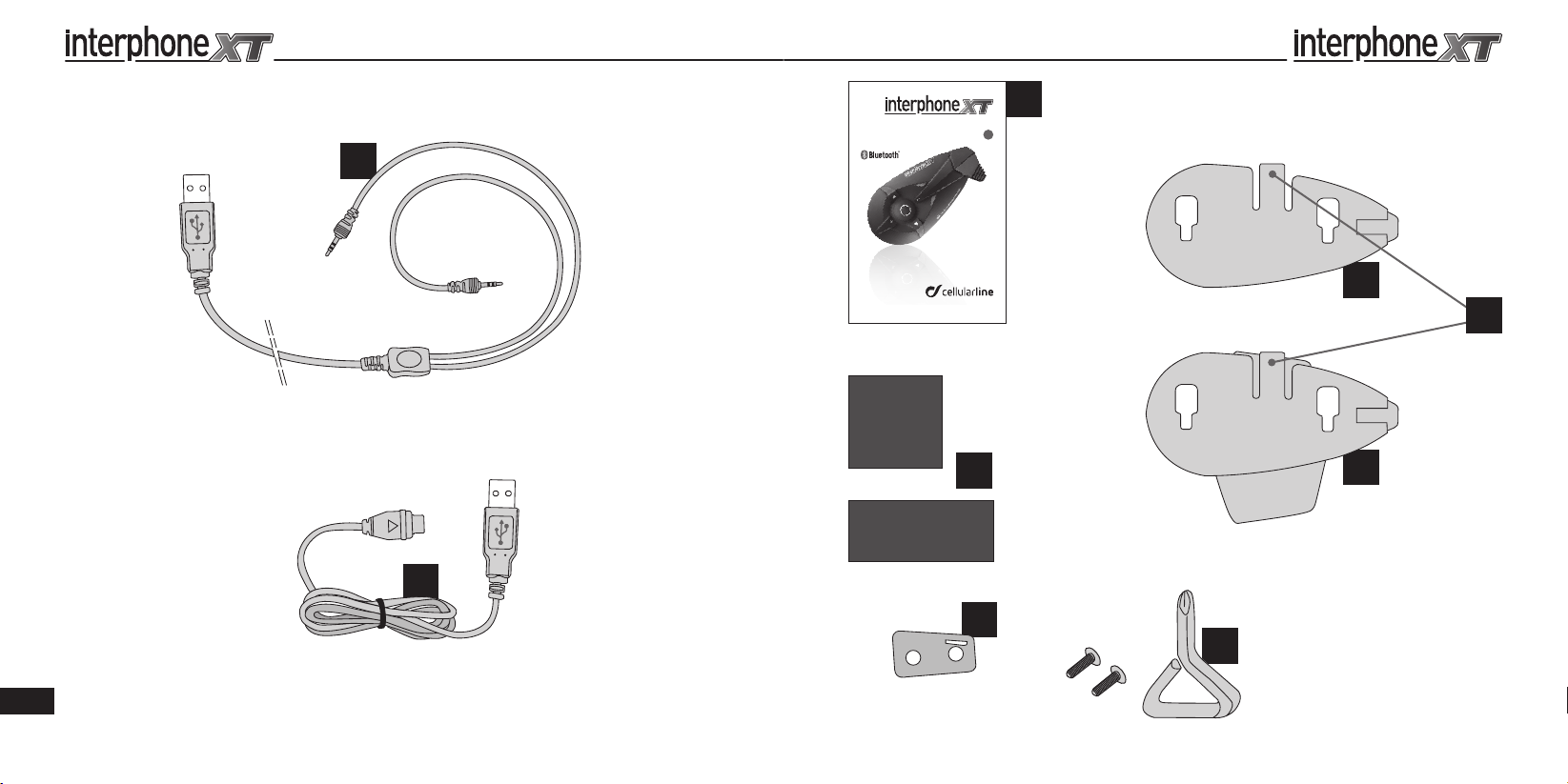
Contents of the package
a) Bluetooth® control panel
b) Stereo earphone equipped with a microphone with foam
windscreen, on a flexible arm (universal)
c) Stereo earphone with wired microphone for full-face helmets
d) Removable clip-on support
e) Permanent adhesive-based support
f ) USB cable for recharging
g) USB cable for updating
i) Velcro adhesive strips
j) Clip adapter
k) Screwdriver
l) Instruction manual
NOTES: in the package containing two F5 kits, components
a - b - c- d - e - i - j - k are doubled.
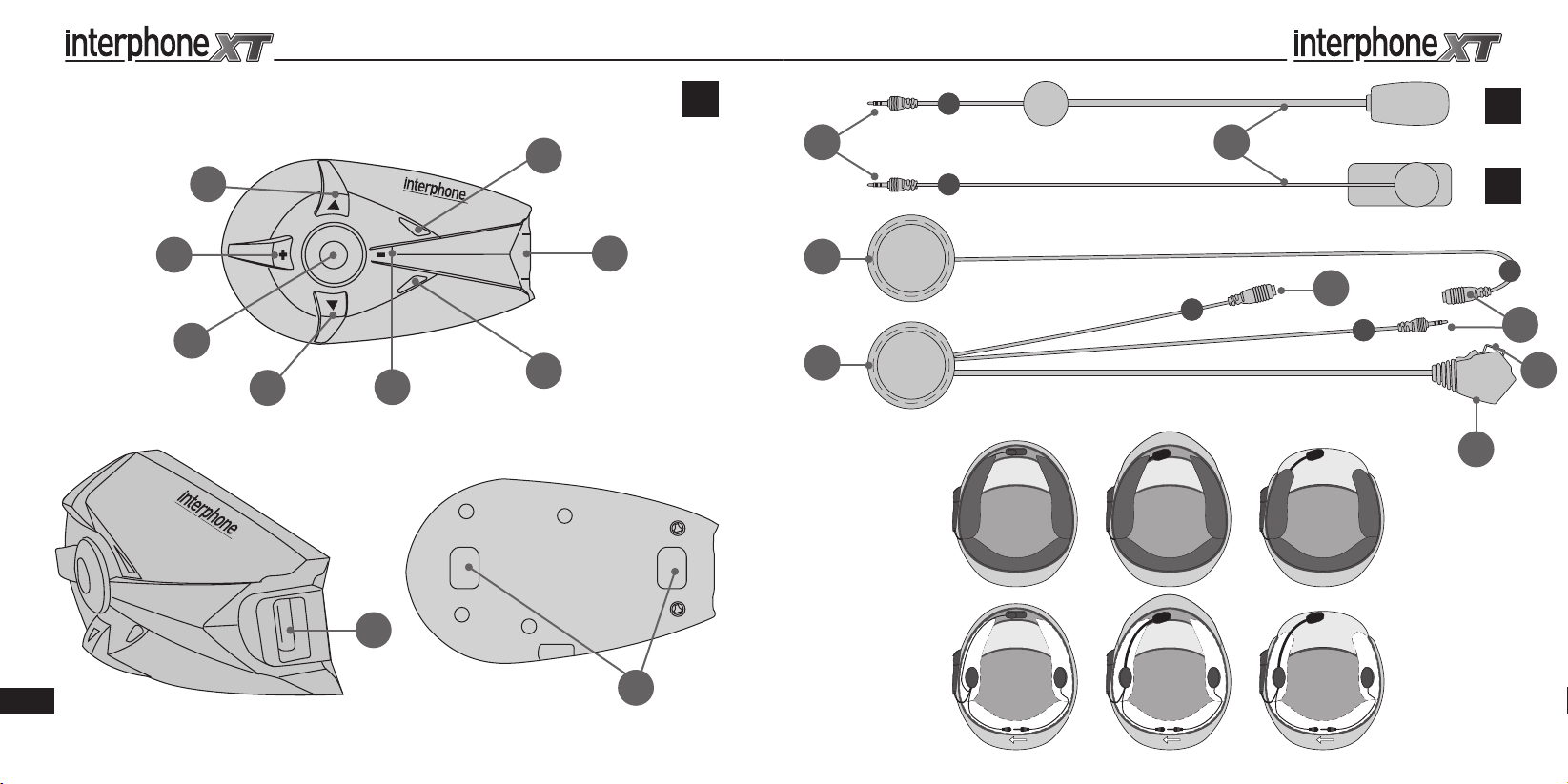
Product description
InterphoneF3XT Bluetooth® module
1) Multi-purpose button
2) Menu UP button
3) Menu DOWN button
4) + Volume button
5) - Volume button
6) Multifunction LED
7) Multifunction LED
8) Multifunction socket
9) Bluetooth® module connection guide
Audio unit for open-face, modular and full-face helmets:
10) Left earphone
11) Right earphone
12) Left/Right earphone connectors
13) Microphone connectors (B or C)
14) Microphone with foam windscreen
15) Connection plug
16) Recharge socket
Care and maintenance
If not using the kit for long periods of time, the battery must be
charged every two/three months, to avoid damage.
To clean, use a damp sponge and mild soap, if necessary. Do not
use solvents or degreasing products to clean the module.
Important note: to prevent water from seeping in through the
audio connector and damaging the module during cleaning, be
sure to insert the plug from the audio section into the socket,
as when the unit is installed and used on the helmet. The kit is
watertight only when the audio plug is inserted.
WARNINGS: If radio interference is high due to the vicinity of
repeaters, high voltage towers or various kinds of radio signals,
intercom communication and/or the InterphoneF3XT device
itself could shut down.
To restore operation, try moving away from the area of interference and/or turn the InterphoneF3XT off and then back on.
Assistance and Warranty
This product is covered by a warranty that complies with the
laws in the country where the unit was purchased.
All information necessary for product assistance or spare parts can
be found on our website www.interphone.cellularline.com.
EN
EN
FR
FR
ES
ES
DE
DE
CS
CS
NL
NL
RU
RU
PL
PL
SV
SV
FI
FI
PT
PT
JP
JP
Page 7
IT14IT
1.0 PREPARATION/ASSEMBLY
InterphoneF3XT is a modular audio kit made up of a Bluetooth® module (the core of the system) (A), a double slide
support system for the module (E/D) and an audio kit with
a double microphone to be installed inside the helmet (C/B)
Before configuring the InterphoneF3XT, you should check
the website for software updates that could improve the
performance of the F3XT. If there are any updates, installation is recommended.
Verify compatibility with the operating system on your PC,
then download the file and the attached instructions that
will guide you through the update process.
1.1 Mounting the bracket on the helmet
The InterphoneF3XT has two mounting systems (small
plates) (E/D) that you can install on the helmet. Choose the
system that is better suited to the type of helmet you are
using.
Equipped with a sliding latch system, the plates support and
lock the F3XT Bluetooth® module into position. One system
is applied using an adhesive system (E), and the other uses
a clip (D).
Thanks to the sliding latch system on the plates, the F3XT
module can easily be removed for recharging, updating,
security against theft, and use on other helmets that have
already been prepared with other kits designed for each
type of helmet.
The kits for an additional helmet all consist of an audio section with earphones/microphone, along with two support
plates for the module.
The kits for an additional helmet are optional and can
have a different structure and operation. For more information, consult the accessory section on our website,
www.interphone.cellularline.com
We recommend using the adhesive plate (E) since it is
more aerodynamic and can be placed wherever you like on
the surface of the helmet. This allows you to choose point
that best suits the shape of the helmet shell to maximize appearance and adhesion.
On the other hand, the adhesive plate cannot be repositioned. Once it is applied, it cannot be removed because the
3M adhesive that provides its excellent holding power does
not allow for a change of position. If the plate is removed, it
must be replaced with a new one.
Carefully choose the most suitable point before application.
The clip-on plate (D) is better for those who do not want
to apply permanent adhesive to their helmet or would like
to be able to remove the plate and use the helmet with no
accessories installed.
The clip-on plate requires that the helmet allow part of the
plate to be inserted between helmet shell and cheekpad.
The cheekpads on some helmets are glued or have special
seals that prevent the plate from being inserted correctly or
require the helmet to be modified, which not everyone is
willing to do. In these cases, it’s better to choose the adhesive plate.
Both brackets can only be installed on the left side of the
helmet.
Installation with (adhesive) plate
Take the adhesive plate, but do not remove the protective
film on the back. Place the plate on the left side of the helmet shell. Now, move it around and find the position where
it will adhere and function best. Before applying it, mount
the F3XT module on the plate and check whether the position you chose could disturb the driver by causing interference or discomfort (check visor, opening, etc...).
Carefully clean and degrease the point chosen for applying the plate. Do not use strong detergents that could ruin
the paint on the helmet. After cleaning the helmet shell,
remove the protective film from the double-sided adhesive
strip and apply the plate on the helmet. Press quickly on the
plate to attach the strip firmly.
After application, it is a good idea to let the 3M adhesive act
on the helmet for 12 hours before using the helmet.
Installation with the clip-on (removable) plate
Check the type of helmet you have and make sure that the
clip can be inserted between helmet shell and cheekpad.
Otherwise, use the adhesive plate.
Take the clip-on plate, loosen the two screws and remove
the rear section.
On the left side of the helmet, locate the most suitable point
for inserting the clip, slide the rear section of the clip in between the helmet shell and the cheekpad, and let the end
(with the holes for the screws) protrude on the outside. Now,
try to join the front section of the clip onto the rear section.
Depending on the thickness/radius of the helmet, it may be
necessary to use the adapter (J) to compensate for the distance between the two sections so that the clip still adheres
to the helmet shell when the screws are tightened.
Tighten the screws with the screwdriver provided. Do not
use excessive force when tightening the screws. You could
break all or part of the clip.
If you are also using the adapter for the clip, you must replace the two screws installed in the clip with the longer
ones supplied with the unit.
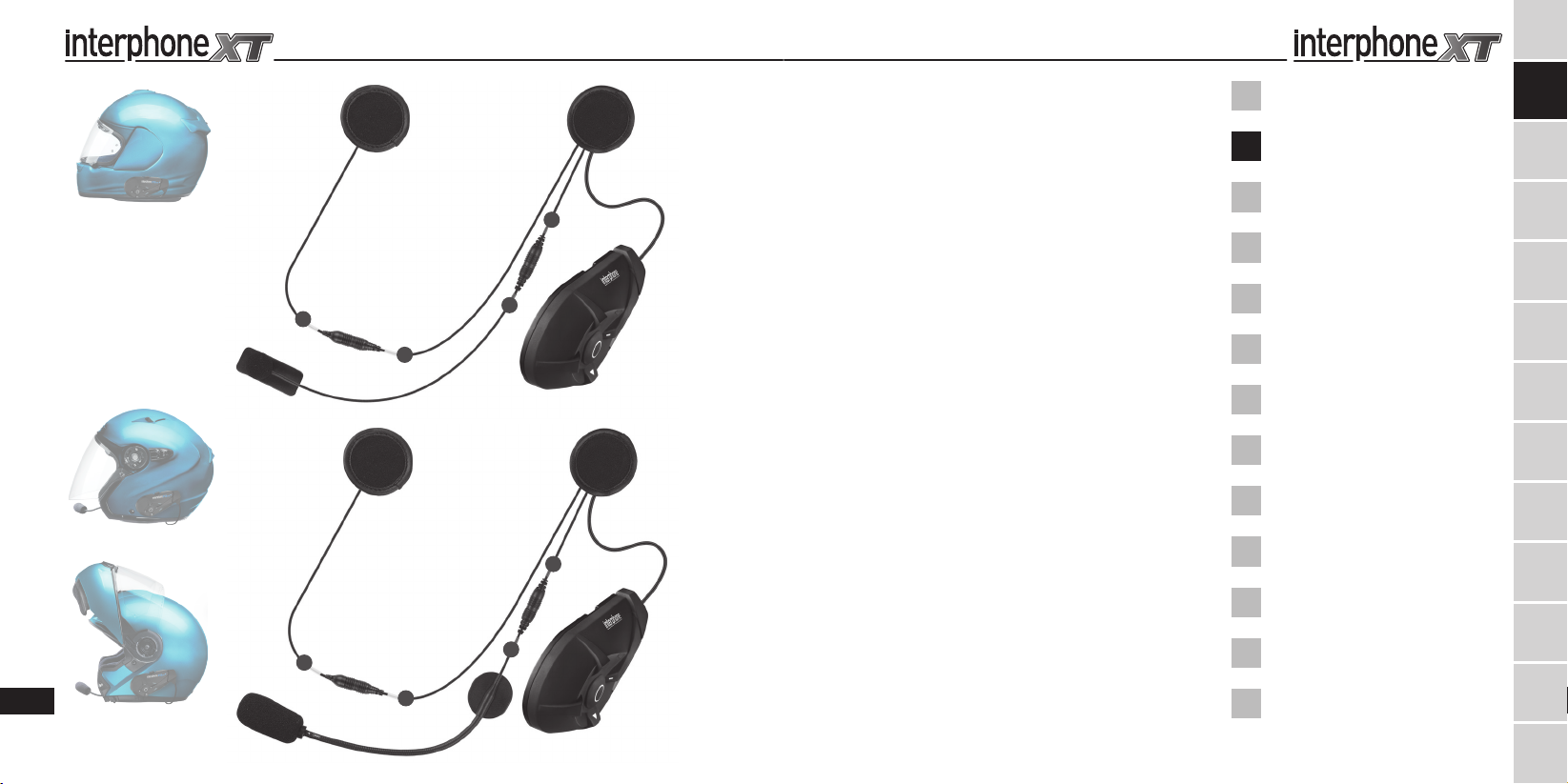
1.2 Audio sec tion (microphone/earphones) (C/B)
InterphoneF3XT with audio kit with two microphones,
connected to the earphone with a mini jack to be able
to choose the most suitable based on the type of helmet.
This makes mounting easy and possible on open-face
and modular as well as full-face helmets.
Open-face/modular helmets use the kit with the micro-
phone mounted on a flexible metal arm (B), since the
arm must remain suspended in front of the user’s mouth.
Full-face helmets use the audio kit with the microphone
connected to the earphone by a thin wire (C) that can be
handled and hidden easily during installation. The micro-
phone is encapsulated in a strip of flexible rubber and is
applied on the inside of the chin strap with adhesive or
Velcro, in front of the user’s mouth.
The right earphone is connected to the audio section
with a moveable mini-jack. Use only the left earphone
in countries where the use of a double earphone is pro-
hibited.
Installing the audio section
Wear the helmet and locate the exact point where your
ears are positioned inside.
If the internal fabric of the helmet allows it, try to apply
the two earphones in the audio kit directly at the points
you determined. The Velcro on the back of the earphone
will often adhere perfectly to the material in the helmet
without the need to use the fabric strip (I) with double-
adhesive. Otherwise, if the material is unmanageable,
apply the strip of fabric at the point you previously deter-
mined and place the earphone on the strip.
Put on the helmet once again and check whether the ear-
phones are correctly positioned. They must be centred
and come slightly in contact with your ears.
If the helmet allows it, it’s a good idea to insert the ear-
phones under the cheekpad fabric, which requires more
time and care to accomplish but makes the internal kit
almost invisible and more comfortable.
Thread the cable with plug under the cheekpad and
around the helmet while trying not to lay it over itself or
twist it. Then, pull it out on the left side as far as it will
go. Afterwards, when the plug is connected to the F3XT
module mounted on the support, you can push the ex-
cess cable back inside and leave only as much as you
need on the outside.
Microphone on open-face/modular helmets (B) - if
possible, slide the microphone arm through the hole in
the chin strap and below the cheekpad so that the micro-
phone is more stable and less obtrusive. It should be pos-
sible to position the microphone with foam windscreen
(14) in front of your mouth, but it may be left slightly to
the side of the mouth.
After installation is complete, make sure that the wording
MIC on the foam windscreen on the microphone arm faces your mouth and preferably points toward your eyes.
Microphone on full-face helmets (C) - the wire from the
microphone must exit from under the cheekpad, and the
microphone (14) must be installed on the inside of the
chin guard and in front of the mouth.
Make sure that the microphone as installed does not
block any ventilation holes, and check that the ventilation holes are not pointing directly at the microphone.
The microphone can be installed directly using the builtin double-sided tape (fixed mounting).
1.3 Recharging
The InterphoneF3XT must be charged before use.
Once mounted on the helmet, connect the recharger cable provided (F) to a USB port, then insert the recharger
cable plug into the outlet on the audio kit connector (16)
correctly inserted in the InterphoneF3XT module.
The charge LED turns orange (7) during charging.
When the battery is fully charged, the LED will turn green.
About two hours are needed to charge the F3XT module completely. Two modules can be charged together in
around three hours.
We recommend turning the module off before recharging the F3XT.
1.4 Turning on/off
TURNING ON
Press and hold the MFB button for approximately 3 seconds.
The speaker will sound an acoustic warning and the LEDs will
begin flashing quickly for around 3 seconds.
Subsequently, in stand-by mode, the LED will flash approximately once every 5 seconds.
TURNING OFF
Press and hold the MFB button. The speaker will sound a prolonged acoustic warning and the LED will flash red prior to
turning off.
2 PAIRING
2.1 Telephone
Pairing
The INTERPHONE F3XT can be paired to a mobile phone.
After having turned the INTERPHONE F3XT off, press and
hold the MFB button until the warning light alternates red
and blue ashes. This will take about 8 seconds.
When the light is flashing red/blue alternately perform the
device search from your telephone (refer to the telephone or
navigator manual).
EN
EN
FR
FR
ES
ES
DE
DE
CS
CS
NL
NL
RU
RU
PL
PL
SV
SV
FI
FI
PT
PT
JP
JP
Page 8
IT
The telephone or navigator will detect the INTERPHONE
F3XT. Simply select it, and enter the numerical code 0000.
To use with a mobile telephone and GPS navigator at the
same time, see point 2.4.
2.2 Intercom
Pairing
After having turned the INTERPHONE F3XT off, press and
hold the MFB button until the warning light alternates red
and blue ashes. This will take about 8 seconds.
When both LEDs flash red/blue alternately, press and release
the MFB button on one of the two INTERPHONE F3XTs.
The two INTERPHONE F3XTs are connected when both LEDs
show a fixed blue light.
2.3 Audio GPS
Pairing
For an audio connection, GPS NAVIGATORS use the TELEPHONE (headset) profile: to pair the phone during use of the
navigator you must use the specific function on the GPS device. For further information and settings, please consult the
navigator manual.
3 USE
3.1 Telephone function
To answer a call: when a call comes in, the speaker sounds a
warning tone or the telephone ring: to answer, briefly press
the MFB button.
To end a call: simply press and release the MFB button.
Voice call: some telephones allow you to make a voice call
simply by pressing and releasing the MFB button.
To refuse a call: press and hold the MFB button for approximately 4 seconds. To refuse a call in VOX mode follow the
instructions in the VOX FUNCTIONS section.
Volume adjustments: to adjust the volume, press the Volume
+ or Volume - keys depending upon the volume desired.
3.2 Intercom function
To enable the Intercom function: to activate a conversation in
the Intercom profile, press the MFB button on one of the two
INTERPHONE F3XTs, and hold for about 3 seconds. An audible warning will advise you when connection has occurred.
Conversation in intercom mode is full-duplex.
To disable intercom function, simply press and release the
MFB button.
Volume adjustments: to adjust the volume, press the Volume
+ or Volume - keys depending upon the volume desired.
3.3 Telephone + Intercom function
With this combination, the connection to the telephone function takes priority.
• During a telephone conversation, intercom communication
is not permitted.
• In order to activate the Intercom function, no telephone call
must be under way: press the MFB button for about 3 seconds. An audible signal will advise you that connection has
been made. Conversation in intercom mode is full-duplex.
• To end a conversation in intercom mode, simply press and
release the MFB button.
• During an intercom conversation, you can answer or refuse
an incoming telephone call. Intercom communication will
be interrupted and re-activated automatically at the end of
the call.
• To answer a telephone call, press and release the MFB button.
• To end a telephone call, press and release the MFB button.
• To refuse the incoming call, press and hold the MFB button
for approximately 4 seconds.
• To adjust the volume, press the Volume + or Volume - keys
depending upon the volume desired.
3.4 Voice response (VOX )
The voice response function allows you to answer a call without having to press any buttons.
Voice response activation: press and hold the Volume +
button until the third beep. An acoustic sound will advise you
that the operation is complete.
Voice response deactivation: press and hold the Volume -
button until the third beep. An acoustic sound will advise you
that the operation is complete.
To answer a call: when receiving a call, simply say a word
(e.g. ‘HELLO’) within ten seconds, to activate the line.
To refuse a call: when receiving a call, simply allow ten seconds to pass and it will be refused.
3.5 Voice call
The voice call function allows you to make a call without using the telephone keys. INTERPHONE F3XT is compatible
with the voice call functions on various Bluetooth® mobile
phones. To activate it and access the commands, refer to the
mobile phone instruction manual.
Please refer to Use - Telephone section.
3.6 Bluetooth® Music
If you’ve paired a mobile phone or GPS unit that can handle
MP3 files and send them using the A2DP Bluetooth® stereo
profile, you can listen and manage music from the F3XT.
You can play/pause by pressing the UP button for two sec-
onds, forward/reverse through songs by briefly pressing the
UP or DOWN buttons, and adjust the volume by pressing the
buttons repeatedly until the desired level is reached.
Music cannot be shared by two or more users. Each user can
only listen to and control the music coming from his or her
player.
If you don’t have a phone, or if your phone does not have
MP3/Bluetooth®, you can use an MP3 Bluetooth® player to
send audio using the A2DP stereo profile.
WE RECOMMEND CHECKING FOR
UPDATES ON THE WEBSITE
WWW.INTERPHONE.CELLULARLINE.COM
Federal Communications Commission (FCC) Statement
Industry Canada (IC) Statement
15.21
You are cautioned that changes or modifications not expressly approved
by the part responsible for compliance could void the user’s authority to
operate the equipment.
15.105(b)
This equipment has been tested and found to comply with the limits for
a Class B digital device, pursuant to part 15 of the FCC/IC rules. These
limits are designed to provide reasonable protection against harmful
interference in a residential installation. This equipment generates, uses
and can radiate radio frequency energy and, if not installed and used
in accordance with the instructions, may cause harmful interference to
radio communications.
However, there is no guarantee that interference will not occur in a particular installation. If this equipment does cause harmful interference to
radio or television reception, which can be determined by turning the
(Applicable in those countries of the European Union with recycling
systems)
The symbol shown on this product or on its documents indicates that
the product must not be disposed of with other domestic refuse at the
end of its life cycle. To avoid damage to the environment or to health
caused by the inappropriate disposal of refuse, the user is requested to
separate this product from other refuse and to recycle it responsibly to
favour the sustainable re-use of material resources.
Domestic users are invited to contact the sales point where the product
was purchased or the local office with information regarding recycling
of this type of product.
Business users are invited to contact their suppliers and to check terms
and conditions of purchase. This product must not be disposed of together with other commercial refuse.
This product bears the CE mark in conformity with the regulations of
the R & TTE Directive (99/5/EC). Cellular Italia S.p.A. hereby declares that
this product conforms to essential standards and other norms under
Directive 1999/5/EC. The user is forbidden from making variations or
modifications of any kind to the device. Any variations or modifications
not expressly approved by Cellular Italia S.p.A. will cancel the user’s authorisation for the use of the device. The Bluetooth® trademark is the
property of Bluetooth® SIG, Inc.
For further information please consult http://www.cellularline.com
This product has an embedded, non-replaceable battery, do not attempt to open the product or remove the battery as this may cause injury and damage the product. Please contact the local recycling facility
for removal of the battery. The embedded, non-replaceable battery is
designed to last the life time of the product.
equipment off and on, the user is encouraged to try to correct the interference by one or more of the following measures:
- Reorient or relocate the receiving antenna.
- Increase the separation between the equipment and receiver.
- Connect the equipment into an outlet on a circuit different from that to
which the receiver is connected.
- Consult the dealer or an experienced radio/TV technician for help.
Operation is subject to the following two conditions:
1) this device may not cause interference and
2) this device must accept any interference, including interference that
may cause undesired operation of the device.
FCC/IC RF Radiation Exposure Statement:
This equipment complies with FCC/IC radiation exposure limits set forth
for an uncontrolled environment. End users must follow the specific operating instructions for satisfying RF exposure compliance. This transmitter must not be co-located or operating in conjunction with any other
antenna or transmitter.
0560
EN
EN
FR
FR
ES
ES
DE
DE
CS
CS
NL
NL
RU
RU
PL
PL
SV
SV
FI
FI
PT
PT
JP
JP
Page 9
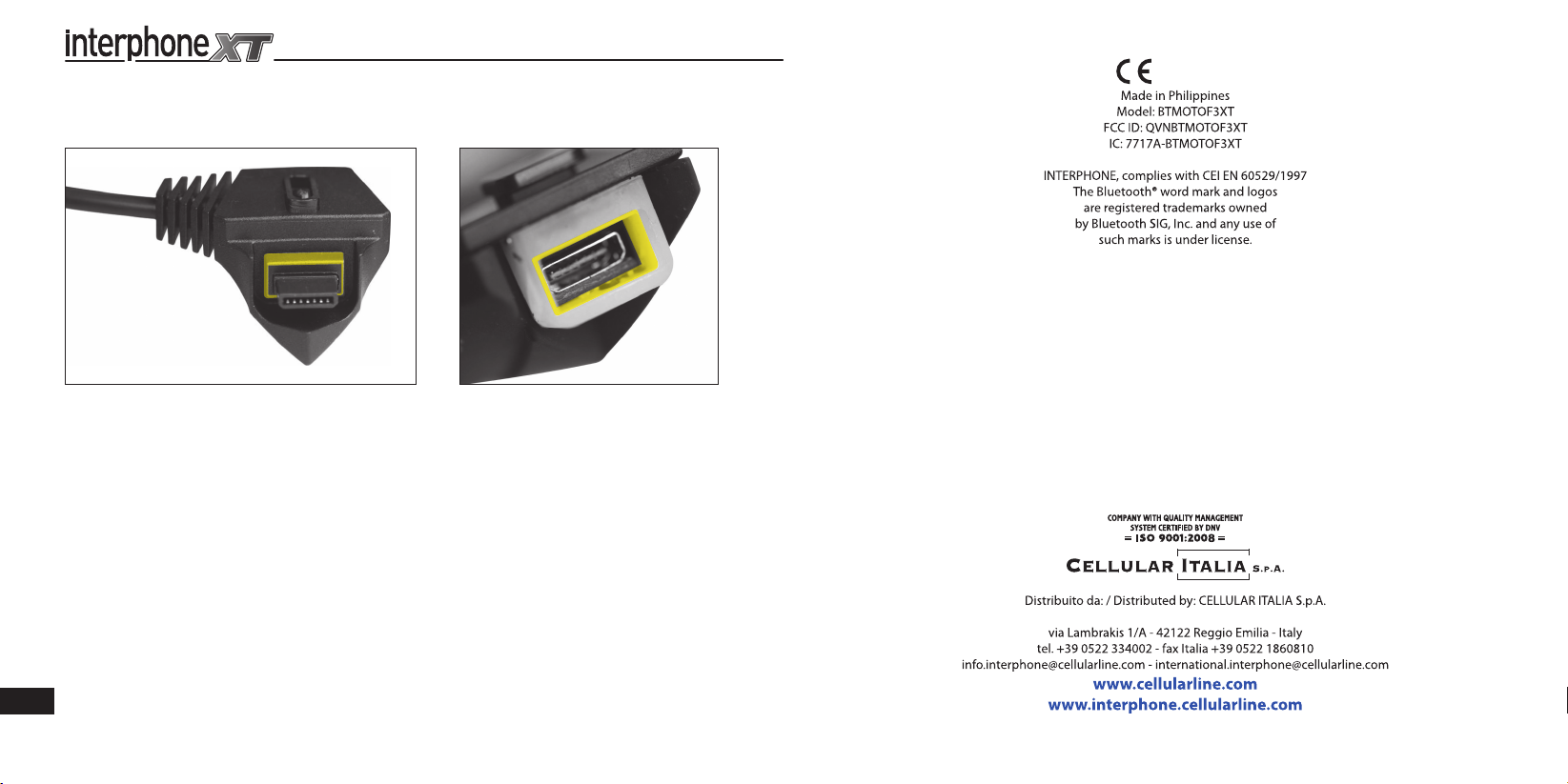
NOTE
For excellent waterproofing, apply a thin layer of silicone on the parts highlighted in the image below.
0560
ISTRINTERPHF3XT
16
 Loading...