


iSPAN™ 5535 PRI
PCI ISDN Adapter
Users Guide
Document No. UG05535-000, REVB2
Print Date: July 2002

NOTE
See Appendix I for Regulatory Statements/Conditions
that affect the operation of this product.
The CE Declaration of Conformity can be found at
www.iphase.com

Copyright Notice
© 2002 by Interphase Corporation. All rights reserved.
Printed in the United States of America, 2002.
This manual is licensed by Interphase to the user for internal use only and is protected by
copyright. The user is authorized to download and print a copy of this manual if the user
has purchased one or more of the Interphase adapters described herein. All copies of this
manual shall include the copyright notice contained herein. No part of this manual,
whether modified or not, may be incorporated into user’s documentation without prior
written approval of
Interphase Corporation
13800 Senlac
Dallas, Texas 75234
Phone: (214) 654-5000
Fax: (214) 654-5500
Disclaimer
Information in this manual supersedes any preliminary specifications, preliminary data
sheets, and prior versions of this manual. While every effort has been made to ensure the
accuracy of this manual, Interphase Corporation assumes no liability resulting from
omissions, or from the use of information obtained from this manual. Interphase
Corporation reserves the right to revise this manual without obligation to notify any
person of such revision. Information available after the printing of this manual will be in
one or more Read Me First documents. Each product shipment includes all current Read
Me First documents. All current Read Me First documents are also available on our web
site.
THIS MANUAL IS PROVIDED “AS IS.” INTERPHASE DISCLAIMS ALL
WARRANTIES, EXPRESS OR IMPLIED, INCLUDING THOSE OF
MERCHANTABILITY AND FITNESS FOR A PARTICULAR PURPOSE OR
ARISING FROM A COURSE OF DEALING, USAGE, OR TRADE PRACTICE.
IN NO EVENT SHALL INTERPHASE BE LIABLE FOR ANY INDIRECT,
SPECIAL, CONSEQUENTIAL, OR INCIDENTAL DAMAGES, INCLUDING,
WITHOUT LIMITATION, LOST PROFITS OR LOSS OR DAMAGE TO DATA
ARISING OUT OF THE USE OR INABILITY TO USE THIS MANUAL, EVEN IF
ADVISED OF THE POSSIBILITY OF SUCH DAMAGES.
Trademark Acknowledgments
Interphase® and the Interphase logo are registered trademarks, (i)chip™, SynWatch™,
FibreView™, ENTIA™, PowerSAN™, SlotOptomizer™, iWAR E ™ , iNAV™, and
iSPAN™ are trademarks of Interphase Corporation.
All other trademarks are the property of their respective manufacturers.

Assistance
Product Purchased from Reseller
Contact the reseller or distributor if:
• you need ordering, service or any technical assistance
• you received a damaged, incomplete or incorrect product.
Product Purchased Directly from Interphase Corporation
Contact Interphase Corporation directly for assistance with this, or
any other Interphase Corporation product. Please have your
purchase order and serial numbers ready.
Customer Service
United States: Telephone: (214) 654-5666
Fax: (214) 654-5500
E-Mail: intouch@iphase.com
Europe: Telephone: + 33 (0) 1 41 15 44 00
Fax: + 33 (0) 1 41 15 12 13
Wor ld Wide Web
http://www.iphase.com

Safety Precautions
The following general safety precautions must be observed during all
phases of operation of this equipment. Failure to comply with these
precautions or with specific warnings elsewhere in this manual violates
safety standards of design, manufacture, and intended use of the
equipment. Interphase Corporation assumes no liability for the user’s
failure to comply with these requirements. As the user of the product,
you must observe all stated warnings and safety precautions in order to
safely operate the equipment in your environment.
Do Not Substitute Parts or Modify Equipment
Because of the danger of introducing additional hazards, do not install
substitute parts or perform any unauthorized modification of the
equipment. Contact your local Interphase representative for service and
repair to ensure that safety features are maintained.
Ground the Instrument
To minimize shock hazard, the equipment chassis and enclosure must be
connected to an electrical ground. The power cable must either be
plugged into an approved three-contact electrical outlet or used with a
three-contact to two-contact adapter, with the grounding wire (green)
firmly connected to an electrical ground (safety ground) at the power
outlet.
Do Not Operate in an Explosive Atmosphere
Do not operate the equipment in the presence of flammable gases or
fumes. Operation of any electrical equipment in such an environment
constitutes a definite safety hazard.
Keep away from Live Circuits
Do not install or replace the component with power cables connected.
Under certain conditions, dangerous voltages may exist even with the
power cable removed. To avoid injuries, always disconnect power and
discharge circuits before touching them.

Telephone Lines Unsafe Voltages
As unsafe voltages (Telecommunication Network Voltages) exist on
ISDN lines, safety precautions must be taken to prevent contact with any
dangerous area of the system.
WARNING
■ The ISDN cable(s) must remain disconnected from the
telecommunications system until the card has been
installed in the system.
■ The installation of the card in the host system must be
done in a way that ensures at least 2mm of air gap
between the Printed Circuit Board (PCB) card and any
other components in the host system, so that the
unsafe area remains located only on the ISDN card.
■ The modem card must only be used in a host system
with a screw-down cover / lid in order to protect the
operator.
Telephone Wiring Warnings
Never install telephone wiring during a lightning storm. Never install
telephone jacks in wet locations unless the jack is specifically designed
for wet locations. Never touch non-isolated telephone wires or terminals
unless the telephone line has been disconnected at the network interface.
Any intervention on the card or in its proximity should be made with the
telephone connector unplugged.
Observe Dangerous Procedure Warnings
Warnings precede potentially dangerous procedures throughout this
manual. Instructions contained in the warnings must be followed. You
should also employ all other safety precautions which you deem
necessary for the operation of the equipment in your operating
environment.

WARNING
This equipment generates, uses, and can radiate
electromagnetic energy. It may cause or be susceptible to
electromagnetic interference (EMI) if not installed and
used in a cabinet with adequate EMI protection.

END-USER LICENSE AGREEMENT
FOR INTERPHASE CORPORATION SOFTWARE
IMPORTANT NOTICE TO USER–READ CAREFULLY
THIS END-USER LICENSE AGREEMENT FOR INTERPHASE CORPORATION
SOFTWARE (“AGREEMENT”) IS A LEGAL AGREEMENT BETWEEN YOU
(EITHER AN INDIVIDUAL OR SINGLE ENTITY) AND INTERPHASE
CORPORATION FOR THE SOFTWARE PRODUCTS ENCLOSED HEREIN WHICH
INCLUDES COMPUTER SOFTWARE AND PRINTED MATERIALS
(“SOFTWARE”). BY INSTALLING, COPYING, OR OTHERWISE USING THE
ENCLOSED SOFTWARE, YOU AGREE TO BE BOUND BY THE TERMS OF THIS
AGREEMENT. IF YOU DO NOT AGREE TO THE TERMS AND CONDITIONS OF
THIS AGREEMENT, PROMPTLY RETURN, WITHIN THIRTY DAYS, THE
UNUSED SOFTWARE TO THE PLACE FROM WHICH YOU OBTAINED IT FOR A
FULL REFUND.
The Software is protected by copyright laws and international copyright treaties, as well
as other intellectual property laws and treaties. The Software is licensed, not sold.
Grant of License: You are granted a personal license to install and use the Software on
a single computer solely for internal use and to make one copy of the Software in
machine readable form solely for backup purposes.
Restrictions on Use: You may not reverse engineer, decompile, or disassemble the
Software. You may not distribute copies of the Software to others or electronically
transfer the Software from one computer to another over a network. You may not use the
Software from multiple locations of a multi-user or networked system at any time. You
may not use this software on any product for which it was not intended. You may not use
this software on any non-Interphase product. LICENSEE MAY NOT RENT, LEASE,
LOAN, OR RESELL THE SOFTWARE OR ANY PART THEREOF.
Ownership of Software: Interphase or its vendors retain all title to the Software, and all
copies thereof, and no title to the Software, or any intellectual property in the Software,
is being transferred.
Software Transfer: You may permanently transfer all of your rights under this
Agreement, provided you retain no copies, you transfer all the Software, and the recipient
agrees to the terms of this Agreement.
Limited Warranty: Interphase Corporation (“Seller”) warrants that (i) the hardware
provided to Buyer (“Products”) shall, at the F.O.B. point, be free from defects in
materials and workmanship for a period of one (1) year from the date of shipment to
Buyer; (ii) the software and/or firmware associated with or embedded in the Products
shall comply with the applicable specifications for a period of six (6) months from the
date of shipment to Buyer; and (iii) its services will, when performed, be of good quality.
Defective and nonconforming Products and software must be held for Seller’s inspection
and returned at Seller’s request, freight prepaid, to the original F.O.B. point.
Upon Buyer’s submission of a claim in accordance with Seller’s Return and Repair
Policy, Seller will, at its option either (i) repair or replace the nonconforming Product;
(ii) correct or replace the software/firmware; (iii) rework the nonconforming services; or
(iv) refund an equitable portion of the purchase price attributable to such nonconforming
Products, software, or services. Seller shall not be liable for the cost of removal or
installation of products or any unauthorized warranty work, nor shall Seller be

responsible for any transportation costs, unless expressly authorized in writing by Seller.
This warranty does not cover damage to the Product resulting from accident, disaster,
misuse, negligence, improper maintenance, or modification or repair of the Product other
than by Seller. Any Products or software replaced by Seller will become the property of
Seller.
REMEDIES AND EXCLUSIONS. THE SOLE LIABILITY OF SELLER AND
BUYER’S SOLE REMEDY FOR BREACH OF THESE WARRANTIES SHALL BE
LIMITED TO REPAIR OR REPLACEMENT OF THE PRODUCTS OR
CORRECTION OF THAT PART OF THE SOFTWARE, WHICH FAILS TO
CONFORM TO THESE WARRANTIES. EXCEPT AS EXPRESSLY STATED
HEREIN, AND EXCEPT AS TO TITLE, THERE ARE NO OTHER WARRANTIES,
EXPRESS OR IMPLIED, INCLUDING WARRANTIES OF MERCHANTABILITY
OR FITNESS FOR ANY PARTICULAR PURPOSE, IN CONNECTION WITH OR
ARISING OUT OF ANY PRODUCT OR SOFTWARE PROVIDED TO BUYER.
IN NO EVENT SHALL SELLER HAVE ANY LIABILITY FOR INDIRECT,
INCIDENTAL, SPECIAL OR CONSEQUENTIAL DAMAGES, HOWEVER
CAUSED AND ON ANY THEORY OF LIABILITY, ARISING OUT OF THESE
WARRANTIES, INCLUDING BUT NOT LIMITED TO LOSS OF ANTICIPATED
PROFITS, LOSS OF DATA, USE OR GOODWILL, EVEN IF ADVISED OF THE
POSSIBILITY OF SUCH DAMAGES. (IC-199, 1/97)
Limitation of Liability: NEITHER INTERPHASE NOR ITS LICENSORS SHALL BE
LIABLE FOR ANY GENERAL, INDIRECT, CONSEQUENTIAL, INCIDENTAL, OR
OTHER DAMAGES ARISING OUT OF THIS AGREEMENT EVEN IF ADVISED OF
THE POSSIBILITY OF SUCH DAMAGES.
Confidentiality: The Software is copyrighted and contains proprietary and confidential
trade secret information of Interphase and its vendors. Licensee agrees to maintain the
Software in confidence and not to disclose the Software to any third party without the
express written consent of Interphase. Licensee further agrees to take all reasonable
precautions to prevent access to the Software by unauthorized persons.
Termination: Without prejudice to any other rights, Interphase may terminate this
Agreement if you fail to comply with any term or condition of the Agreement. In such
event you must destroy the Software together with all copies, updates, or modifications
thereof.
Export: You agree to comply with all export and re-export restrictions and regulations
of the U.S. Department of Commerce or other applicable U.S. agency. You must not
transfer the Software to a prohibited country or otherwise violate any such restrictions or
regulations.
U.S. Government Restricted Rights: Use, duplication, or disclosure of the Software to
or by the U.S. Government is subject to restrictions as set forth in the applicable U.S.
federal procurement regulations covering commercial/restricted rights software. You are
responsible for complying with the notice requirements contained in such regulations.
General: You acknowledge that you have read and understand this Agreement, and by
installing and using the Software you agree to be bound by the terms and conditions
herein. You further agree that this is the complete and exclusive Agreement between
Interphase and yourself. No variation of the terms of this Agreement or any different
terms will be enforceable against Interphase unless agreed to in writing by Interphase and
yourself. The validity of this Agreement and the rights, obligations, and relations of the
parties hereunder shall be determined under the substantive laws of the State of Texas. If

any provision of this Agreement is held invalid, illegal, or unenforceable, the remaining
provisions shall in no way be affected or impaired thereby. All rights in the Software not
specifically granted in this Agreement are reserved by Interphase.

1Contents
Using This Guide........................................................................................ vii
Audience ............................................................................................... vii
Icon Conventions................................................................................. vii
Text Conventions ............................................................................... viii
Documentation Updates ...................................................................... ix
Driver Updates........................................................................................x
CHAPTER 1 Introduction
Adapter Overview
RAS Support Overview.........................................................................2
Product Features ...............................................................................3
Minimum System Requirements..........................................................4
Software Drivers.....................................................................................5
CHAPTER 2 Installing the Hardware
Overview
Verifying Minimum Requirements......................................................7
Inspecting the Adapter...........................................................................7
Installing the Adapter ............................................................................9
Connecting the Adapter to an MVIP Bus.........................................14
CHAPTER 3 Connecting to the Line
Overview
North America T1/PRI Line ...............................................................17
..................................................................................................7
Requirements for MVIP Bus Electrical Termination................15
How to Configure MVIP Electrical Termination
on the iSPAN-PRI
................................................................................................17
..................................................................................1
.......................................................................16
iSPAN PRI PCI ISDN Users Guide i

Connecting directly to the line without a CSU..........................18
Connecting directly to the line with an internal CSU...............19
Connecting to the line through an external CSU....................... 20
T1/PRI Cabling ....................................................................................22
T1 Link Requirements................................................................... 22
European E1/PRI Line ........................................................................23
Connection Method........................................................................ 23
E1/PRI Cabling Requirements ..................................................... 23
E1 Link Requirements................................................................... 24
Connector Pinouts................................................................................24
Connecting the Adapter to the Network...........................................25
CHAPTER 4 Installing the Software
Overview
...............................................................................................27
Verifying Minimum Requirements ................................................... 27
Installing and Setting Up the Drivers................................................28
Setting up RAS Support Properties .............................................36
Setting Up ISDN B Channels as RAS Ports ..............................38
Checking the ISDN Line with LoopTest....................................43
Removing the Drivers ......................................................................... 46
CHAPTER 5 Setting Up WAN Firmware and Hardware
Overview
...............................................................................................51
Accessing Online Help........................................................................ 51
Managing Firmware and Hardware...................................................52
Firmware Management..................................................................53
Hardware Management .................................................................55
Setting Up ISDN PRI Port Properties............................................... 56
Configuring the Switch Type ....................................................... 57
Selecting the CRC Type (Europe Only) ..................................... 58
Editing DS1 Properties (North America Only) ......................... 58
ii Interphase Corporation

CHAPTER 6 Setting Up RAS Support Properties
Overview
................................................................................................63
Accessing Online Help ........................................................................63
Determining RAS Support Parameters .............................................64
CHAPTER 7 Troubleshooting
Overview
................................................................................................67
Interpreting Adapter LEDs .................................................................67
North America.................................................................................68
Europe (Other than France)...........................................................69
France ...............................................................................................70
Problems and Possible Solutions .......................................................72
APPENDIX A Specifications
Adapter Specifications
.........................................................................77
Operating Environment .......................................................................77
Storage Environment ...........................................................................78
APPENDIX B Using the SynWatch Utility
Overview
................................................................................................79
Accessing Online Help ........................................................................80
Starting SynWatch................................................................................80
Mouse Button Functions .....................................................................82
Watching ISDN Channels...................................................................82
Watching the ISDN D Channel ....................................................82
Watching ISDN B Channels .........................................................84
Watching ISDN Layer 1 Alarms........................................................85
Stopping and Freezing the Display....................................................86
Changing the Watch Mode .................................................................86
Editing ISDN Channel Settings..........................................................87
Saving and Editing Frames .................................................................88
iSPAN PRI PCI ISDN Users Guide iii

APPENDIX C Using the LoopTest Utility
Overview
...............................................................................................89
Accessing Online Help........................................................................ 90
Testing your ISDN Line...................................................................... 90
Displaying and Saving Events ...........................................................92
Setting the Number of Frames to Send.............................................93
Understanding LoopTest Messages .................................................. 94
APPENDIX D Using RAS Utilities
Overview
...............................................................................................97
RAS Manager .......................................................................................97
RasTracker ............................................................................................98
Routing and Remote Access Service ................................................ 98
APPENDIX E Using the LineTest Utility
Overview
.............................................................................................101
Accessing Online Help......................................................................101
Determining the Current Port Mode ...............................................102
Setting Port and Clock Modes .........................................................102
Loopback Mode............................................................................104
PRBS Generator and Monitor Mode .........................................105
Operational Mode......................................................................... 106
Clock Modes .................................................................................106
APPENDIX F Using the LineStatus Utility
Overview
.............................................................................................109
Accessing Online Help......................................................................109
Interpreting LineStatus Indicators ...................................................110
Alarm LEDs ..................................................................................111
Error LEDs .................................................................................... 112
Loopback LEDs............................................................................112
Statistics Parameters .................................................................... 113
iv Interphase Corporation

APPENDIX G Quick Reference of Common Tasks
Overview
..............................................................................................115
Index of Common Tasks ...................................................................115
Procedures ...........................................................................................116
APPENDIX H ISDN Technology Overview
Overview
..............................................................................................125
Basic Rate Interface ...........................................................................125
Primary Rate Interface.......................................................................126
APPENDIX I Regulatory Statements
FCC
.......................................................................................................127
Canada..................................................................................................129
Europe ..................................................................................................131
EN60950–IEC950 Security Standard..............................................132
Accessory.......................................................................................132
Glossary.......................................................................................................133
Index.............................................................................................................143
iSPAN PRI PCI ISDN Users Guide v

vi Interphase Corporation

2Using This Guide
Audience
This manual assumes that its audience has a general
understanding of computing and networking terminology. If
you need more information about this terminology (in addition
to what this manual provides), see the following web sites:
• ISDN links:
http://www.bellcore.com/nic
http://www.via-isdn.org
http://www.comware.com/telcom/telcolnk.htm
• Networking glossary:
http://www.ctcnet.com/tips/glossary.htm
Icon Conventions
Icons draw your attention to especially important information,
such as the following:
NOTE
The Note icon indicates important points of interest
related to the current subject.
iSPAN PRI PCI ISDN Users Guide vii

Text Conventions
CAUTION
The Caution icon brings to your attention those items or
steps that, if not properly followed, could cause problems
in your machine’s configuration or operating system.
WARNING
The Warning icon alerts you to steps or procedures that
could be hazardous to your health, cause permanent
damage to the equipment, or impose unpredictable
results on the surrounding environment.
Text Conventions
The following conventions are used in this manual. Computergenerated text is shown in typewriter font. Examples of
computer-generated text are: program output (such as the
screen display during the software installation procedure),
commands, directory names, file names, variables, prompts,
and sections of program code.
Example of computer-generated text
Commands to be entered by the user are printed in bold
Courier type. For example:
cd /usr/tmp
Pressing the return key (
command line entry is assumed, when not explicitly shown.
For example:
viii Interphase Corporation
↵ Return) at the end of the

/bin/su
is the same as:
Using This Guide
/bin/su
Required user input, when mixed with program output, is
printed in bold Courier type.
↵ Return
Documentation Updates
The latest documentation (in Adobe® Acrobat® pdf) for our
current products are available on our WWW site. Interphase
recommends our customers visit the web site to verify that they
have the latest version of the documentation.
1. Access the following web page:
http://www.iphase.com
2. Move the mouse (or other pointer) and click on the
Products option. A menu will appear on the left side
with Telecom Solutions, Enterprise Solutions, and
Services options. Choose the appropriate menu item
(such as PowerSAN Fibre Channel HBAs).
3. A new web page with a list of the currently offered
products will appear. Choose your product by clicking
on the product number (i.e. 4532, 5540, 4575, etc.).
4. The Product Description page appears for the product
selected. At the left side of the page is a list showing
additional information web pages for that product.
Choose the User Guides item.
5. A new web page appears with a list of the latest released
user guides available for the product. Click on the
document you require.
iSPAN PRI PCI ISDN Users Guide ix

Driver Updates
Driver Updates
Contact our Technical Support Department at
swlib@iphase.com to determine if updated drivers are
available for your product.
When contacting technical support, please be sure to provide
your name, company name and address, phone number,
product name, driver version (if applicable), OS and version (if
applicable) and serial number. Providing this information will
help speed up our response.
x Interphase Corporation
1Introduction
Adapter Overview
The iSPAN™ PRI (Primary Rate Interface) adapter is a
Peripheral Component (PCI) add-on board for PCI-based PCs,
servers, and workstations. It enables systems to connect to one
or two ISDN primary rate interfaces.
The single-PRI version is powered by the IBM
403GA 32-bit RISC processor at 33 MHz.
The dual-PRI version is powered by the IBM PowerPC
403GCX 32-bit RISC processor at 66 MHz, and combined
with a 32-bit/33-MHz PCI interface. It provides a fast pathway
to enterprise communication server applications.
1
®
PowerPC™
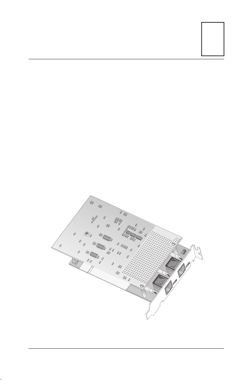
Figure 1-1. iSPAN PRI PCI ISDN Adapter (Dual PRI Version)
iSPAN PRI PCI ISDN Users Guide 1

RAS Support Overview
RAS Support Overview
This adapter supports Microsoft® Remote Access Service
(RAS), which enables remote user connections over ISDN
lines. RAS enables the transport of TCP/IP, IPX/SPX, and
NetBEUI protocols.
RAS supports all of the mainstream networking clients,
including the following:
• Windows for Workgroups
• LAN Manager
• Windows 95
• Windows NT Workstations
• Windows NT Servers
• UNIX
• Macintosh
• NetWare
• OS/2-based clients.
RAS connection enables all services typically available to a
LAN-connected user (including file- and print-sharing,
database access, and messaging) , as shown in the following
illustration:
2 Interphase Corporation
Figure 1-2. RAS Features
Chapter 1: Introduction
Product Features
• PCI 2.1 compliant master/target bus interface
• North America and Europe ISDN Compatibility
(NET3, E-DSS1, NI-1, NI-2)
• Conforms to all industry standards and specifications
(FCC part 15 class A and part 68, CE class A, IEC950)
• Single PRI version:
– 32-bit RISC processor PowerPC 403GA @ 33 MHz
– 4-MB dual port DRAM memory and 128 KB Flash
EEPROM
– RAS support for up to 30 B channels and 1 D
channel (Europe) or 23 B channels and 1 D channel
(United States and Japan)
iSPAN PRI PCI ISDN Users Guide 3

Minimum System Requirements
• Dual PRI version:
– 32-bit RISC processor PowerPC 403GCX @
66 MHz
– 8-MB dual port DRAM memory and 128-KB Flash
EEPROM
– RAS support for up to 60 B channels and 2 D
channels (Europe) or 46 B channels and 2 D
channels (United States and Japan)
• 32-bit, 33-MHz local bus
• HDLC and transparent mode on each B channel
• Short PCI form factor (174.63 x 106.68 mm)
• Full plug-and-play installation.
Minimum System Requirements
The minimum system requirements for using this adapter with
Microsoft Remote Access Service (RAS) are:
• An Intel
(either Workstation or Server)
®
system running Windows NT Version 4.0
• Bus architecture: PCI Local Bus Specification Revision
2.1
• Processor: Pentium at 133 MHz
• 32 MB RAM (you may need up to 128 MB depending
on your RAS configuration and usage)
• A hard disk with 3 MB free
• A 3.5" diskette drive or a CD-ROM drive
• Single PRI version: One functional ISDN primary rate
interface
• Dual PRI version: One or two functional ISDN primary
rate interfaces
4 Interphase Corporation
• CSU (Channel Service Unit)
(For more information, see North America T1/PRI Line
on page 17).
Software Drivers
You can install only one iSPAN-PRI PCI ISDN adapter per
system. Each adapter requires the following drivers:
• WAN adapter driver for Windows NT: the basic driver
required to support the adapter
• RAS Support: the driver required to support Microsoft
Remote Access Service over ISDN. Enables the
transport of TCP/IP, IPX/SPX, and NetBEUI protocols
over ISDN lines.
These drivers are both installed during the installation
procedure.
The general software architecture is as follows:
Chapter 1: Introduction
Figure 1-3. Software Architecture Overview
iSPAN PRI PCI ISDN Users Guide 5

Software Drivers
The complete iSPAN-PRI software is stored on a single
diskette or a CD-ROM included in the adapter package.
6 Interphase Corporation

2Installing the Hardware
Overview
You can install the iSPAN-PRI adapter in any suitable PCI
expansion slot. To install your adapter, follow these basic
steps:
1. Verify that the system meets minimum requirements.
2. Inspect the adapter.
3. Install the adapter in a host expansion slot.
4. Connect the adapter to an MVIP Bus, if required.
The tools required are a grounding strap and a #1 Phillips head
screwdriver. Both are delivered with the product and are
included in the packaging.
2
Verifying Minimum Requirements
Before installing this adapter, verify that your system meets
the minimum requirements described in Minimum System
Requirements on page 4.
Inspecting the Adapter
Before installing the adapter in your computer, you need to
visually inspect it for any damage that might have occurred
during shipment from the factory.
iSPAN PRI PCI ISDN Users Guide 7

Inspecting the Adapter
CAUTION
The adapter is packed in an antistatic bag to protect it
during shipment. Keep the adapter in its protective
antistatic bag until you are ready to install it in the host
computer. To prevent damage to the adapter due to
electrostatic discharge, wear a grounding strap on your
wrist or ankle and handle the adapter only by its edges. Do
not touch its components or any metal parts other than
the faceplate. If your adapter is a fiber adapter, do not
remove the connector cap(s) until you’re ready to install
the adapter.
1. Open the shipping container and carefully remove its
contents.
2. Inspect each item for damage. If you find any omissions
or damage, contact your network supplier and the
carrier (for example, UPS or Federal Express) that
delivered the package.
8 Interphase Corporation

Installing the Adapter
WARNING
Your computer operates at voltages that can be lethal.
Follow all cautions and warnings in this installation
procedure, both to protect yourself and prevent damage
to your computer. Use only tools with nonconductive
handles, or tools coated with, covered with, or made with
nonconductive materials. Nonconductive materials are
materials that do not conduct electric current, such as
With a grounding strap connected to your wrist or ankle, do the
following to install the adapter:
Chapter 2: Installing the Hardware
iSPAN PRI PCI ISDN Users Guide 9
Installing the Adapter
1. Turn off the computer’s power switch, and unplug the
unit from its power source.
Figure 2-1. Unplugging the Computer
2. Disconnect all cables connected to the main system
unit, and remove the computer cover according to the
manufacturer’s instructions.
10 Interphase Corporation

Chapter 2: Installing the Hardware
Figure 2-2. Removing the Computer Cover
3. Locate a suitable PCI expansion slot, and remove the
screw that attaches the expansion plate to the computer.
Save the screw for Step 6.
CAUTION
If you plan to connect the adapter to an MVIP bus, the
location of the adapter depends on the other MVIP
adapters. See Connecting the Adapter to an MVIP Bus on
page 14 for instructions before proceeding with the
installation process.
iSPAN PRI PCI ISDN Users Guide 11

Installing the Adapter
4. Remove the expansion plate.
Figure 2-3. Removing the Expansion Plate
12 Interphase Corporation

Chapter 2: Installing the Hardware
5. Carefully remove the adapter from its antistatic bag, and
position the adapter in the PCI expansion slot. Align the
adapter’s connector pins with the slot’s receptacle; then
press gently but firmly on the board to seat it in the slot.
6. Attach the adapter with the screw removed in step 3.
Figure 2-4. Inserting the Adapter
iSPAN PRI PCI ISDN Users Guide 13

Connecting the Adapter to an MVIP Bus
NOTE
If you need to connect the adapter to other MVIP
telephony processing adapters in the cabinet, such as
voice, data, fax, video or image processing adapters, and
have not already done so, see Connecting the Adapter to
an MVIP Bus on page 14.
7. Replace the computer cover.
You are now ready to connect the adapter to the appropriate
PRI line, as described in Connecting to the Line on page 17.
Connecting the Adapter to an MVIP Bus
You must connect the adapter to an MVIP bus if you plan to
integrate the adapter with other MVIP telephony processing
adapters, such as voice, data, fax, video or image processing
adapters. To create a dedicated interconnection between these
adapters, connect a ribbon cable to the 40-pin, double-row,
right-angled headers on the top edge of all MVIP adapters.
For optimal electrical signal quality on the MVIP ribbon cable,
you must place the MVIP adapters in a specific order
(depending on the number of connections), and electrically
terminate two MVIP clock signals.
14 Interphase Corporation

Chapter 2: Installing the Hardware
Requirements for MVIP Bus Electrical Termination
For systems with five or fewer MVIP bus connections and less
than 90 pF load on the clock lines, it is adequate to place the
circuit board that is the master clock source at one end of the
cable and electrically terminate the MVIP bus only on the
circuit board located at the other end of the cable.
NOTE
The iSPAN-PRI adapter is generally the master clock
source, because it is connected to the network. In this
case, place the
cable.
On systems with more than five MVIP bus connections or
more than 90 pF of load on the clock lines, both ends of the
cable must be electrically terminated. No other boards should
be electrically terminated.
iSPAN-PRI adapter at one end of the
If the iSPAN-PRI adapter is at one of the MVIP cable ends,
you must set the dip switches to their ON position (down) to
complete the required electrical termination. Consult the
relevant manuals for other MVIP adapters to correctly
configure their specific electrical termination.
If you do not connect the iSPAN-PRI to an MVI P bus, you c a n
leave the dip-switches, located close to the 40-pin double-row
right-angled header, on any position.
iSPAN PRI PCI ISDN Users Guide 15

Connecting the Adapter to an MVIP Bus
How to Configure MVIP Electrical Termination on the iSPAN-PRI
The factory default configuration for the iSPAN-PRI adapter
does not require jumpers.
If the adapter does not have to be electrically terminated, do
not insert any jumpers into the 2-pin connectors.
If this is the last board in a multiple MVIP bus configuration,
the iSPAN-PRI adapter requires electrical termination in the
MVIP bus. To provide the required electrical termination,
place two jumpers on the two 2-pin connectors located next to
the MVIP connector, as described in the following figure.
Figure 2-5. Electrically Terminating the MVIP Bus.
16 Interphase Corporation

3Connecting to the Line
Overview
The type of line your carrier provides depends on whether you
are in North America or Europe. This chapter provides the
following information required to connect your adapter to the
line:
• connection methods and requirements for connecting to
a North American T1/PRI line
• connection methods and requirements for connecting to
a European E1/PRI line
• summary of steps to connect the adapter to the network.
If you are in North America, continue with the next section.
If you are in Europe, skip to European E1/PRI Line on
page 23.
3
North America T1/PRI Line
When you connect the adapter to a North American T1/PRI
line, first determine the appropriate connection method,
cabling requirements, and link requirements.
Two T1/PR1 line configurations exist: DSX1 (short haul) and
DS1 (long haul). When the distance to your carrier is short
enough (less than 655 feet or 200 meters), you can generally
connect the adapter in a DSX1 configuration directly to the
T1/PR1 line. All iSPAN-PRI adapters support the DSX1
configuration.
iSPAN PRI PCI ISDN Users Guide 17

North America T1/PRI Line
If the distance is longer (up to 6200 feet or 1800 meters), you
need to connect the adapter in a DS1 configuration. In this
configuration, a Channel Service Unit (CSU) must translate
the short haul DSX1 interface in order to support the longer
distance.
The iSPAN-PRI adapter optionally supports an internal CSU.
In this case, you can connect the adapter directly to the T1/PRI
line, also in a DS1 configuration. If your adapter does not
include this option (and if the distance is too long), you will
need to connect the adapter to an external CSU, which itself
will be connected to the metallic T1/PR1 interface.
Connecting directly to the line without a CSU
You can connect the iSPAN-PRI directly to the line without
any internal or external CSU if the distance to your carrier is
short enough (less than 655 feet or 200 meters). The line will
be in a DSX1 configuration (short haul). See Figure 3-1.
Less than 655 feet (200m)
WAN Adapter
Telco
Figure 3-1. Adapter connected directly to the Telco
Direct connection is subject to constraints imposed by FCC
rules and by your partner carrier. For more information about
these constraints, and to find out if you can connect directly to
the interface, contact your carrier.
18 Interphase Corporation

Chapter 3: Connecting to the Line
WARNING
To avoid harming the WAN, you must first contact your
carrier for approval before connecting the adapter to the
line.
CAUTION
In accordance with FCC Rules, Part 68.218 (b), you must
notify the telephone company prior to disconnecting the
adapter from the line or turning off the power to the
adapter’s host system. Without this prior notification, the
carrier might temporarily discontinue your T1/PRI service.
Connecting directly to the line with an internal CSU
If your iSPAN-PRI adapter includes the internal CSU option,
you can connect it directly to the line and be up to 6200 feet
(1.8 km) far from your carrier. The line will be in a DS1
configuration (long haul).
Figure 3-2. Adapter with an internal CSU
iSPAN PRI PCI ISDN Users Guide 19

North America T1/PRI Line
WARNING
To avoid harming the WAN, you must first contact your
carrier for approval before connecting the adapter to the
line.
CAUTION
In accordance with FCC Rules, Part 68.218 (b), you must
notify the telephone company prior to disconnecting the
adapter from the line or turning off the power to the
adapter’s host system. Without this prior notification, the
carrier might temporarily discontinue your T1/PRI service.
Connecting to the line through an external CSU
If the distance to your carrier is longer than 655 feet (200
meters), or if your carrier does not accept a direction DSX1
connection, and if your iSPAN-PRI adapter does not include
an internal Channel Service Unit (CSU), you need to connect
an external CSU between the adapter and the network.
Figure 3-3. Adapter connected to an external CSU
20 Interphase Corporation

Chapter 3: Connecting to the Line
WARNING
To avoid harming the WAN, you must first contact your
carrier for approval before connecting the CSU to the line.
CAUTION
In accordance with FCC Rules, Part 68.218 (b), you must
notify the telephone company prior to disconnecting the
CSU from the line or turning the CSU’s power off. Without
this prior notification, the carrier might temporarily
discontinue your T1/PRI service.
iSPAN PRI PCI ISDN Users Guide 21

T1/PRI Cabling
T1/PRI Cabling
WARNING
Before connecting the cable, read Telephone Lines
Unsafe Voltages in the Safety Precautions section at the
front of this manual.
The cable between the adapter and the carrier or the CSU must
meet standard T1 attenuation and transmission requirements:
• 100 Ohm
• two twisted pairs, category 3 or higher
• maximum length: 655 feet (200 m) without a CSU,
6200 feet (1800 meters) with a CSU.
The actual cable length between the adapter and the carrier
must be measured and recorded; you will need this information
The cable must include an RJ48C plug at the end dedicated to
the WAN adapter. It must also provide the appropriate plug or
cabling system at the end connected to the carrier or CSU. See
Connector Pinouts on page 24 and relevant carrier or CSU
documentation for more information.
T1 Link Requirements
The adapter and the CSU must be configured with several
common specifications in order to interoperate. The adapter’s
T1 parameters are set to the following:
• Line coding: B8ZS
• Frame format: ESF (Extended Super Frame)
• Line I/O impedance: 100 Ohm ± 5%
22 Interphase Corporation

European E1/PRI Line
When you connect the adapter to a European E1/PRI line, first
determine the appropriate connection method, cabling
requirements, and link requirements.
This section describes the method and requirements for
connecting the adapter to a European E1/PRI line.
Connection Method
Generally, your E1/PRI carrier provides a Network
Termination 1 (NT1) device to interface between the WAN
adapter and the metallic interface of the WAN. You need to
connect the WAN adapter to the NT1.
E1/PRI Cabling Requirements
Chapter 3: Connecting to the Line
WARNING
Before connecting the cable, read Telephone Lines
Unsafe Voltages in the Safety Precautions section at the
front of this manual.
The cable between the adapter and the NT1 must meet the
following standard E1 attenuation and transmission
requirements:
• 120 Ohm
• two twisted pairs, category 3 or better
• maximum length: 200 m (655 feet)
iSPAN PRI PCI ISDN Users Guide 23

Connector Pinouts
The cable must include an RJ48C plug at the end dedicated to
the WAN adapter. It must also provide the appropriate plug or
cabling system at the end dedicated to the NT1. See Connector
Pinouts on page 24 and your NT1 documentation for details.
E1 Link Requirements
To interoperate successfully, the adapter and the NT1 must be
configured with several common E1 settings. The adapter’s E1
parameters are in accordance with the IUT-T I 431
recommendation, as follows:
• Line coding: HDB3, according to IUT-T G.703
• Frame format: according to IUT-T G.704
• CRC4 to Non-CRC4 operation: according to
IUT-T G.706 An.B
• Line I/O impedance: 120 Ohm ± 5%.
Connector Pinouts
The following illustration of the adapter’s faceplate shows the
adapter’s connectors and connector pins:
24 Interphase Corporation
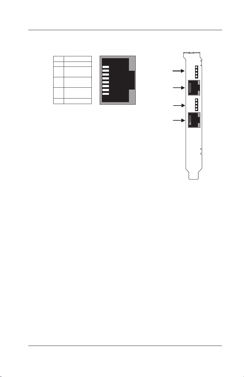
Chapter 3: Connecting to the Line
Signal
Pin
8
7
6
Tx out (tip)
5
Tx out (ring)
4
3
Rx in (tip)
2
Rx in (ring)
1
RJ48C Pinout
8
1
LEDs 1, 2, 3 & 4
(Port #0)
Port #0
(RJ48C)
LEDs 5, 6, 7 & 8
(Port #1)
Port #1
(RJ48C)
Figure 3-4. Adapter’s Faceplate and Connector Pinouts
The adapter’s connectors follow the RJ48C specification.
Four Light Emitting Diodes (LEDs) display the status of the
link (as described in Interpreting Adapter LEDs on page 67).
Connecting the Adapter to the Network
With the adapter installed, you are ready to connect the adapter
to the network, as follows:
1. Obtain the cable required for your type of connection, as
described in T1 Link Requirements on page 22 or
E1/PRI Cabling Requirements on page 23.
2. Attach the appropriate RJ48C-compliant connector to
the adapter.
iSPAN PRI PCI ISDN Users Guide 25

Connecting the Adapter to the Network
3. Reconnect the power cable and turn on the machine.
After connecting the adapter to the network, install the adapter
drivers. See Installing the Software on page 27.
26 Interphase Corporation

4Installing the Software
Overview
This chapter describes the procedures for installing and setting
up your iSPAN-PRI adapter’s software on Microsoft Windows
NT 4.0 workstations. This process installs both the basic WAN
adapter driver and the RAS Support driver.
To install the software, follow these basic steps:
1. Verify that your system meets minimum requirements.
2. Install and set up the drivers.
This chapter also explains how to remove the drivers, if
required.
If Read Me First documentation is included in your installation
kit, review it before installing the driver. It may contain
changes and updates made to this users guide after the print
date.
4
Verifying Minimum Requirements
If you have not already done so, verify that your system meets
the minimum requirements described in Minimum System
Requirements on page 4.
iSPAN PRI PCI ISDN Users Guide 27

Installing and Setting Up the Drivers
Installing and Setting Up the Drivers
To install and set up the adapter drivers, do the following:
1. Install the WAN and RAS Support drivers.
2. Set up RAS support properties.
3. Set up ISDN B channels.
4. Check the ISDN line with the LoopTest utility.
NOTE
The iSPAN-PRI adapter is called either 5535-1P-PRI or
5535-2P-PRI in the software installation and configuration
Installing the Drivers
Before you start, make sure the adapter is installed in your
machine, and that you are logged on with administrator rights
to the Windows NT 4.0 system.
To install the WAN and RAS support drivers for the adapter:
1. From the Start menu, select Settings, and then Control
Panel. Then double-click the Network icon to display
the Network Identification dialog:
28 Interphase Corporation

Chapter 4: Installing the Software
Figure 4-1. Network Identification tab of the Network dialog
2. Select the Adapters tab to display the Adapters dialog:
iSPAN PRI PCI ISDN Users Guide 29

Installing and Setting Up the Drivers
Figure 4-2. Network Adapters tab of the Network dialog
3. Click Add to begin loading the drivers.
The system creates an adapter list in the Select Network
Adapter dialog:
30 Interphase Corporation

Chapter 4: Installing the Software
Figure 4-3. Network Adapters List
4. Click Have Disk.
The Insert Disk dialog appears, prompting you to insert
the disk and identify the file location:
Figure 4-4. Insert Disk dialog
iSPAN PRI PCI ISDN Users Guide 31
Installing and Setting Up the Drivers
5. If you are installing the software from a diskette, insert
the diskette, change the installation directory to A:\ and
click OK.
If you are installing the software from a CD-ROM,
insert the CD-ROM. If ‘D:’ is the letter assigned to the
CD-ROM drive, change it to D:\5535PRI (or select the
appropriate drive) and click OK.
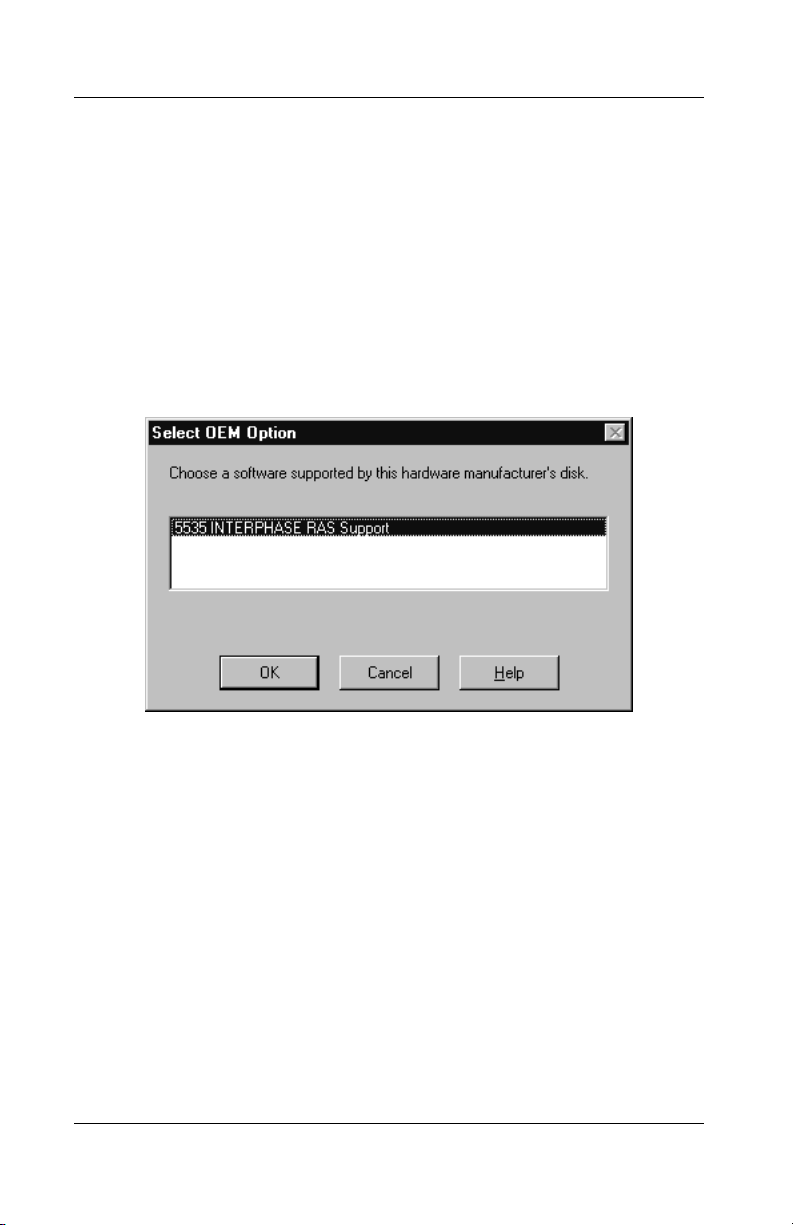
The Select OEM Option dialog appears, with 5535
INTERPHASE RAS Support selected:
Figure 4-5. Select OEM Option dialog
6. Click OK to confirm the selection.
The INTERPHASE WAN Adapter driver window
appears, prompting you to accept or change the
installation directory and begin installation.
You can install the iSPAN-PRI adapter from a diskette or from
CD-ROM as follows.
32 Interphase Corporation

Chapter 4: Installing the Software
Figure 4-6. WAN Adapter Driver Installation
7. If needed, change the default installation path in the
Copy To field to the desired pathname.
8. Click Continue to install the driver.
The installation program copies product files to the
directory specified in the Copy To field, and creates a
program group in the Windows NT Start menu.
Next, the WAN Adapters setup dialog appears:
iSPAN PRI PCI ISDN Users Guide 33

Installing and Setting Up the Drivers
Figure 4-7. WAN Adapters Setup
The adapter is automatically detected. The Cards list
should be updated to include the iSPAN-PRI adapter
(listed as a version of the 5535) in your machine.
NOTE
If the cards list is empty, the adapter might not be properly
installed. Click OK. Then see Problems and Possible
Solutions on page 72 for information about correcting the
problem.
34 Interphase Corporation

Chapter 4: Installing the Software
9. Make sure the 5535 adapter is selected in the Cards list
of the WAN Adapters Setup dialog. Then do the
following to configure the adapter’s ISDN ports:
a. Select the port you want to configure (from
[0] ISDN PRI to [1] ISDN PRI), and click
Properties to display the ISDN PRI Port Properties
dialog:
Figure 4-8. ISDN PRI Port Properties
b. Select the switch type that corresponds to your ISDN
subscription, and click OK. (For more information
about switch types, see Setting Up ISDN PRI Port
Properties on page 56.)
c. When the WAN Adapters setup dialog reappears,
repeat steps a and b for each ISDN PRI port.
d. When all ISDN ports are configured, click OK.
The configuration software automatically finds
firmware for the adapter. It updates the registry and
dynamically installs the drivers.
iSPAN PRI PCI ISDN Users Guide 35

Installing and Setting Up the Drivers
10. When a message informs you that the driver is running,
click OK.
Figure 4-9. Successful Setup Message
To continue the software installation, set up RAS support
properties as described in the next section.
Setting up RAS Support Properties
After you respond OK to the message that the driver is
running, the Interphase 5535 RAS Support dialog appears:
Figure 4-10. RAS Support Setup
This dialog enables you to set up RAS Support properties for
the adapter.
36 Interphase Corporation

Chapter 4: Installing the Software
To set up RAS support properties:
1. Click OK to confirm the displayed configuration.
– If Remote Access Service is installed on your
system, a message informs you that RAS support
setup is complete, and states that Remote Access
Services (RAS) setup must now be invoked.
Click OK to update the ISDN port list in RAS setup.
Then skip to Setting Up ISDN B Channels as RAS
Ports on page 38.
– If Remote Access Service is not yet installed on
your system, a message informs you that RAS
support setup is complete, and states that Remote
Access Services (RAS) setup must now be installed:
Click OK, and continue to step 2.
2. When a message informs you that Setup needs to copy
Windows NT files, enter the complete path if you want
Setup to find the files in a location other than the
default:
Figure 4-11. Windows NT Setup Message
3. Click Continue to complete the RAS installation.
iSPAN PRI PCI ISDN Users Guide 37

Installing and Setting Up the Drivers
When RAS installation is complete, a message informs
you that Remote Access Service has been successfully
installed, and reminds you to use Remote Access
Admin or User Manager in the Administrative Tools
Folder to assign RAS permissions to users.
4. Click OK.
To continue the software installation, set up ISDN B channels
as RAS ports, as described in the next section.
Setting Up ISDN B Channels as RAS Ports
After RAS is installed, you can set up ISDN B channels as
RAS ports, using the Add RAS Device dialog:
Figure 4-12. Add RAS Device
This dialog appears after you respond OK to the message that
Remote Access Service must be invoked or that Remote
Access Service has been successfully installed.
To set up the IDSN B channels:
1. Click OK to select the first ISDN B channel (ISDN1-
SynWan).
38 Interphase Corporation

Chapter 4: Installing the Software
The Remote Access Setup dialog appears, with the
ISDN port included in the RAS port list:
Figure 4-13. Remote Access Setup
2. Select the port and click Configure to set up its
connection mode.
The Configure Port Usage dialog appears:
Figure 4-14. Configure Port Usage
3. Select a port usage option, and click OK.
iSPAN PRI PCI ISDN Users Guide 39

Installing and Setting Up the Drivers
The Remote Access Setup dialog reappears (see
Figure 4-13 on page 39). It now shows one ISDN
channel configured as a RAS port.
4. To quickly configure all ISDN channels with the same
port usage as the first ISDN channel:
a. Click Clone until a message informs you there are
no more ports of the specified type to clone.
b. Click OK.
5. When the Remote Access Setup dialog reappears, do
the following to select the protocols (NetBEUI, TCP/IP,
or IPX) and other settings to be bound to the adapter:
a. Click Network to display the Network
Configuration dialog:
40 Interphase Corporation

Chapter 4: Installing the Software
Figure 4-15. Network Configuration
On this dialog, you can select the Enable Multilink
option to allow multiple ISDN B channels to make
one logical network connection. This function
aggregates several ISDN B channels to increase the
bandwidth of PPP links.
For more detailed network configuration
information, see Microsoft’s online help for RAS.
b. Click OK to confirm your network configuration.
c. When the Remote Access Setup dialog reappears,
click Continue.
iSPAN PRI PCI ISDN Users Guide 41

Installing and Setting Up the Drivers
6. The INTERPHASE 5535 RAS ISDN support adapter
now appears in the Network Adapters list on the
Adapters dialog:
Figure 4-16. Network Adapters List
7. Click Close to complete the software installation.
After the software is fully installed, a message informs
you that you must shut down and restart your computer
before the settings take effect.
42 Interphase Corporation

Chapter 4: Installing the Software
CAUTION
If a Windows NT Service Pack was installed on the system
after the first Windows NT installation, you must reinstall
it before restarting the computer. For installation
information, see the latest available version of your
Service Pack help. If you do not reinstall the Service Pack,
the Remote Access Service will probably fail to start, or
will not behave correctly when connecting ISDN lines.
To determine whether a Service Pack is installed, see
Index of Common Tasks on page 115.
8. If the system is a Windows NT basic system, with no
service pack installed, click Yes to restart the computer.
Otherwise, click No. Then reinstall the Windows NT
Service Pack before restarting the system.
Next, continue the software installation by checking the ISDN
line, as described in the next section.
Checking the ISDN Line with LoopTest
After you have installed and configured the adapter software
and restarted Windows NT, you can check your ISDN line
using the LoopTest utility. This utility calls itself and
establishes two ISDN B channels. One of the channels is set to
listen, and the second channel calls the first one.
iSPAN PRI PCI ISDN Users Guide 43

Installing and Setting Up the Drivers
To check the IDSN line using LoopTest:
1. Before executing LoopTest, and to avoid incoming call
conflicts, disable the RAS Server, as follows:
a. From the Start menu, select Programs, then
Administrative Tools (Common), and then
Remote Access Admin. The following dialog
appears:
Figure 4-17. Remote Access Admin Dialog
b. From the Server menu, select Stop Remote Access
Service.
2. After the RAS server is stopped, from the Start menu,
select Programs, then INTERPHASE WAN
Adapters, and then LoopTest.
The LoopTest dialog appears:
44 Interphase Corporation

Chapter 4: Installing the Software
Figure 4-18. LoopTest Dialog
3. Select the port number to test (if your adapter has two
PRI ports), and enter your local ISDN number.
4. Click Test.
The LoopTest Utility normally finishes with the
message Test passed in the Diagnostic field.
If the Test passed message does not appear, make sure
that the ISDN number you entered is correct. For more
information about the LoopTest utility and its
diagnostics, see Using the LoopTest Utility on page 89.
5. Do the following to enable the RAS Server again:
a. From the Start menu, select Programs, then
Administrative Tools (Common), and then Access
Admin.
b. From the Server menu, select Start Remote Access
Service to enable the RAS Server.
iSPAN PRI PCI ISDN Users Guide 45

Removing the Drivers
c. If Windows NT does not display the server name
automatically, enter the server name preceded by
two backslashes (\\). To determine the server name,
see Index of Common Tasks on page 115.
d. Click OK.
To use the adapter in the RAS environment (RAS Server or
RAS Dial-Up Networking), see the following:
• For an overview, see Index of Common Tasks on
page 115.
• For detailed information, see Microsoft RAS online
help.
Removing the Drivers
If you no longer use the adapter, do the following to remove the
WAN and RAS Support drivers:
1. Be sure you are logged on with administrator rights to
the Windows NT 4.0 system.
2. From the Start menu, select Settings, and then Control
Panel. Then double-click the Network icon, and select
the Adapters tab to display the Adapters dialog:
46 Interphase Corporation

Chapter 4: Installing the Software
Figure 4-19. Network Adapters List
3. Select INTERPHASE 5535 RAS ISDN support (for
the iSPAN-PRI), and click Remove.
A warning message informs you that this action will
permanently remove the component, and asks if you
want to continue.
4. Click Yes to continue the driver removal.
iSPAN PRI PCI ISDN Users Guide 47

Removing the Drivers
Figure 4-20. Uninstallation Main Dialog
5. Click Continue to deinstall the WAN Adapters driver.
6. Confirm your choice by clicking Yes when a pop-up
The Interphase WAN Adapters driver dialog identifies
the install path that will be deleted, and asks if you are
sure you want to deinstall the software:
asks you to confirm the card(s) removal and driver
deletion.
After you confirm the deletion, the system does the
following:
– Deletes product files and the WAN Adapter program
group from the Start menu
– Dynamically unloads the drivers from memory
– Cleans up the registry
When the deinstallation process is finished, the
Adapters dialog reappears.
7. Click Close to confirm the new network settings.
The Windows NT Network updates network bindings.
48 Interphase Corporation

Chapter 4: Installing the Software
8. If the iSPAN-PRI adapter was the only RAS-
capable device, a setup message informs you that you
have an invalid RAS configuration. It also reminds you
to configure RAS and add ports using the Network
option in the Control Panel after restarting the system.
Click OK to complete the driver deletion.
NOTE
When the system boots up again, the Remote Access
Service will fail to initialize. (As a result, RAS errors will
appear in the Windows NT Event Viewer). To avoid this
problem, uninstall Remote Access Service after you
uninstall the adapter, as described in Microsoft
documentation and online help. Then restart your
computer.
9. When a message informs you that you must restart your
computer for new settings to take effect, and prompts
you to restart your computer, click Yes.
iSPAN PRI PCI ISDN Users Guide 49

Removing the Drivers
50 Interphase Corporation

5Setting Up WAN
Firmware and Hardware
Overview
The WAN Adapter Setup utility enables you to manage
hardware and firmware for all Interphase WAN adapters. Use
this utility to add and remove Interphase WAN adapters and
their firmware, and to manage ISDN properties for adapter
ports.
The chapter explains how to do the following WAN Adapter
Setup tasks:
• Access online help
• Manage adapter firmware and hardware
• Set up ISDN properties
Accessing Online Help
For detailed information about the functions described in this
chapter, see the WAN Adapter Setup online help. You can
access online help in the following ways:
• Click Help to display the main online help.
• Press F1 to display contextual help in a pop-up window.
5
• Place the cursor on a window control to display a pop-
up with the name of the control.
iSPAN PRI PCI ISDN Users Guide 51

Managing Firmware and Hardware
Managing Firmware and Hardware
NOTE
The iSPAN-PRI is listed as the 5535 adapter in WAN
Adapter Setup dialogs.
Start the WAN Adapter Setup utility in either of the following
ways:
• From the Start menu, select Settings, and then Control
Panel. Then double-click the WAN Setup icon.
• From the Start menu, select Programs, then
INTERPHASE WAN Adapters, and then WAN
Setup.
When you start the utility, the WAN Adapters Setup dialog
appears:
52 Interphase Corporation

Chapter 5: Setting Up WAN Firmware and Hardware
Figure 5-1. WAN Adapters Setup
The WAN Adapters setup dialog has two sections:
• The Microcode section is for firmware management.
• The Cards section is for hardware management.
Firmware Management
The Microcode section of the Wan Adapter Setup dialog
displays firmware information for the currently-selected WAN
adapter. It displays the protocols you can use with the adapter,
and their status. You can view the microcode status, reload the
microcode, or change the microcode.
iSPAN PRI PCI ISDN Users Guide 53

Managing Firmware and Hardware
The firmware status is represented by a general LED color for
the microcode and individual LEDs for each protocol, as
follows:
LED Color For General LED For Individual LEDs
Red No microcode is found on the
disk for the current card.
Gray Microcode is found but is not
loaded into the card.
Yellow Microcode is running on the
card but is different from that
found on the disk for this
card.
Green The microcode is running. The protocol is active.
N/A
The protocol is inactive.
N/A
54 Interphase Corporation

Chapter 5: Setting Up WAN Firmware and Hardware
Use the following buttons to set up microcode information:
Click... To do this...
Load Download the current microcode to the selected adapter.
CAUTION
CAUTION: This option disconnects all
current RAS-connected users and
disables the RAS Server. After a
microcode download, the RAS Server
must be re-enabled, as follows:
1. From the Start menu, select Programs, then
Administrative Tools (Common), and then Remote
Access Admin.
2. From the Server menu, select Stop Remote Access
Service, and then Start Remote Access Service.
New Set an alternate microcode as the current one.
NOTE
The Properties button in the Microcode section is
disabled because this product has no configurable layers.
Hardware Management
The Cards section of the WAN Adapter Setup dialog displays
all the Interphase adapters installed in the machine, their
status, and their available communication ports. The
iSPAN PRI PCI ISDN Users Guide 55

Setting Up ISDN PRI Port Properties
Microcode section displays firmware information for the
adapter selected in the Cards section. You can use the buttons
in this section to add, remove, or configure WAN adapters.
The adapter status is represented by its icon color:
LED Color Meaning
Gray The adapter is detected but is not working.
Yellow The hardware configuration has been changed but not
applied.
Green The adapter is running.
Use the following buttons to set up adapter hardware:
Click... To do this...
Add Add a new adapter. This option is enabled if one more
Interphase adapters can be installed.
Remove Remove an existing adapter. This option removes an adapter
and its drivers.
Properties Display the hardware properties of a selected adapter or the
port properties of a selected port. For ISDN ports, these
properties are essentially subscription parameters, such as
switch type.
Setting Up ISDN PRI Port Properties
NOTE
Before you configure your PRI ISDN line, first obtain the
ISDN switch type from your ISDN provider.
56 Interphase Corporation

Chapter 5: Setting Up WAN Firmware and Hardware
Use the ISDN PRI Port Properties dialog to view and set the
ISDN port switch type (and, for Europe, the CRC type).
To display the ISDN PRI Port Properties dialog:
1. Select the ISDN port you want to configure in the Cards
section of the WAN Adapters setup dialog (shown in
Figure 5-1 on page 53.)
2. Click the Properties button in the Cards section:
The ISDN PRI Port Properties dialog appears:
Figure 5-2. ISDN PRI Port Properties
Configuring the Switch Type
In the ISDN PRI Port Properties dialog, select one of the
following switch type settings, depending on your location and
your ISDN provider’s switch type.
• In North America, select one of the following switch
types:
– Select NT DMS100 NI1 if your telephone company
uses a Northern Telecom DMS-100 switch that
complies with the National ISDN 1(or National
iSPAN PRI PCI ISDN Users Guide 57

Setting Up ISDN PRI Port Properties
ISDN 2) standard (sometimes referred to as
National).
Select AT&T CUSTOM if your telephone
company uses an AT&T 5ESS Custom switch.
All of these switch types offer T1/PRI access (also
called 23B+D).
• In Europe, select ETSI EUROISDN. This switch type
offers E1/PRI access (also called 30B+D).
Selecting the CRC Type (Europe Only)
If your location is Europe, you also need to select the CRC
type in the ISDN PRI Port Properties dialog (shown in
Figure 5-2 on page 57). The CRC type depends on the switch
type (whether E1 or PRI) and the country:
• For European countries other than France, select
CRC4.
• For France, deselect CRC4.
Editing DS1 Properties (North America Only)
If you have selected an American Switch Type, you can edit
the DS1 properties on the DS1 Properties dialog.
To display the DS1 Properties dialog:
1. Select the ISDN port to configure in the Cards section
of the WAN Adapters setup dialog (shown in Figure 5-1
on page 53).
2. Click the Properties button in the Cards section.
3. On the ISDN PRI Port Properties dialog (shown in
Figure 5-2 on page 57), click Edit DS1 Properties.
58 Interphase Corporation

Chapter 5: Setting Up WAN Firmware and Hardware
NOTE
The Edit DS1 Properties button is enabled only when an
American Switch Type is selected.
The DS1 Properties dialog appears:
Figure 5-3. DS1 Properties
Line framing, CRC, and Line code parameters describe
physical level parameters, which cannot be modified on a PRI
Line.
iSPAN PRI PCI ISDN Users Guide 59

Setting Up ISDN PRI Port Properties
The following table describes DS1 options that can be edited:
Option Description
Activate the CSU This option depends on whether the connection between
the adapter and the T1 line requires a CSU:
• Select Activate the CSU to activate a CSU between
the network and the adapter. The CSU is included on
the
iSPAN-PRI adapter. However, to activate the
CSU you must purchase the CSU option. (An external
CSU is not required).
• Deselect Activate the CSU to deactivate a CSU
between the network and the adapter.
The CSU facility is protected by a password. You must
enter this password when selecting ‘Activate the CSU’
for the first time. For password instructions, refer to the
Read Me First information provided in your adapter
package.
Network Line
Build Out
60 Interphase Corporation
The Network line build out compensates for the signal
attenuation due to the length of the cable between the
adapter and the switch.
Four values are available (expressed in dB):
• 0
• 7.5
• 15
• 22.5.
Select the value indicated by your Telco. If this
information is not available, use 0 dB.

Chapter 5: Setting Up WAN Firmware and Hardware
Option Description
Facility Data Link
Protocol(s)
Facility Data Link protocols are used to exchange
messages between the adapter and the remote end of the
network. Such messages are issued by the Telco to put
the adapter in loopback mode for testing when problems
occur. They are also used to transmit statistics about
physical transmission errors on the line.
Two protocols are available for the facility data link: the
ANSI-T1-403 and the ATT-54016 protocol. Both are
compatible with each other.
Use the protocol(s) indicated by your Telco. If this
information is unavailable, the best choice is to use both
protocols.
iSPAN PRI PCI ISDN Users Guide 61

Setting Up ISDN PRI Port Properties
62 Interphase Corporation

6Setting Up RAS
Support Properties
Overview
The RAS Support Setup utility enables you to set up an
inactivity timer for ISDN connections and determine RAS
Support parameters for the adapter.
The chapter explains how to do the following Ras Support
Setup tasks:
• Access online help
• Determine RAS Support parameters
Accessing Online Help
For detailed information about the functions described in this
chapter, see the RAS Support Setup online help. You can
access online help in the following ways:
• Click Help to display the main online help.
6
• Press F1 to display contextual help in a pop-up window.
• Move the cursor over a window control to display a
pop-up with the name of the control.
iSPAN PRI PCI ISDN Users Guide 63

Determining RAS Support Parameters
Determining RAS Support Parameters
You can use the RAS Support dialog to determine the network
name of the adapter and set a timeout limit for adapter ports.
NOTE
The iSPAN-PRI is listed as the 5535 in RAS Support Setup
dialogs.
To access the RAS Support Setup dialog:
1. From the Start menu, select Settings, and then Control
Panel.
2. Double-click the Network icon, and then select the
Adapters tab.
3. On the Adapters dialog, select INTERPHASE 5535
RAS ISDN support (for the iSPAN-PRI) from the
adapters list, and click Properties.
The Interphase 5535 RAS Support dialog appears:
Figure 6-1. RAS Support Dialog
64 Interphase Corporation

Chapter 6: Setting Up RAS Support Properties
The following table describes the parameters in the 5535 RAS
Support dialog fields:
Parameter Function
Adapter Identifies the status and the network name of the adapter.
The LED beside the adapter name represents the adapter
status. Green means that the driver is running, and gray
means that it is not running.
The numeric suffix in the name (in this case, 3) is the logical
network adapter number assigned by Windows NT.
Idle Timeout The Idle timer is an inactivity timer. It is used to disconnect
an ISDN connection when no data traffic is exchanged.
This timer setting is attached to the displayed adapter. The
setting is identical for all of the adapter’s ISDN B channels.
To disable the Idle Timeout, enter
Card Displays the name of the physical 5535 adapter.
0.
iSPAN PRI PCI ISDN Users Guide 65

Determining RAS Support Parameters
66 Interphase Corporation

7Troubleshooting
Overview
This chapter provides possible solutions for common problems
you might encounter while installing and operating your
adapter. Before proceeding with troubleshooting, make sure
you have carefully followed the steps for installing and setting
up the hardware and the software, and have rebooted the
system. Also, check the system log to see what kind of errors,
if any, are being recorded.
If the information in this chapter does not resolve the problem,
contact Interphase Technical Support at one of the locations
listed in the Assistance section at the front of this Users Guide.
Interpreting Adapter LEDs
7
The iSPAN-PRI provides four LEDs above each port:
LED1
LED2
LED3
LED4
Figure 7-1. Adapter LEDs Arrangement
iSPAN PRI PCI ISDN Users Guide 67

Interpreting Adapter LEDs
LED functions differ depending on whether the adapter is
configured to operate in North America (with T1/PRI access),
in European countries other than France (with E1/PRI access
and CRC4), or in France (with E1/PRI access and no CRC
type).
North America
In North America, the adapter LEDs for each port function are
as follows:
LED Color Meaning if the light is ON...
1 Green Clock is synchronized.
2 Green Physical layer is active.
3 Yellow Your ISDN provider is currently sending an RAI alarm
to the adapter.
4 Red Loss Of Signal (LOS), indicating no electrical power is
detected on the line.
In their operational state, the LEDs must be as follows:
LED Color State must be...
1 Green On
2 Green On
3 Yellow Off
4 Red Off
68 Interphase Corporation

Chapter 7: Troubleshooting
The following table describes the adapter status when the
sequence of LEDs appears as follows:
LED1 LED2 LED3 LED4 Meaning
On On Off Off Adapter is operational.
On On On Off A synchronization problem occurred on
the ISDN carrier side.
Off Off Off On No power is detected on the line. Make
sure cable is plugged in correctly.
Off Off Off Off Your ISDN provider is currently sending
an AIS alarm to the adapter.
Europe (Other than France)
In European countries other than France, the adapter LEDs for
each port function are as follows:
LED Color Meaning if the light is ON...
1 Green Clock is synchronized.
2 Green Physical layer is active.
3 Yellow Your ISDN provider is currently sending an RAI alarm
to the adapter.
4 Red Error: CRC4 not found.
In their operational state, the LEDs must be as follows:
LED Color State must be...
1 Green On
2 Green On
3 Yellow Off
4 Red Off
iSPAN PRI PCI ISDN Users Guide 69

Interpreting Adapter LEDs
The following table describes the adapter status when the
sequence of LEDs appears as follows:
LED1 LED2 LED3 LED4 Meaning
On On Off Off Adapter is operational.
On Off On On Your E1/PRI line does not support
CRC4 functionality. Deselect the CRC4
option. (See Setting Up ISDN PRI Port
Properties on page 56.)
On Off On Off Remote Alarm Indication (RAI). Your
ISDN provider has synchronization
problems and is reporting this problem
to you.
On Off Off On Your E1/PRI line does not support
CRC4 functionality. Deselect the CRC4
option. (See Setting Up ISDN PRI Port
Properties on page 56.)
Off Off Off Off No electrical signal is on the E1/PRI
line. Make sure your cable is plugged in
correctly.
France
In France, the adapter LEDs for each port function are as
follows:
LED Color Meaning when the light is ON...
1 Green Clock is synchronized.
2 Green Physical layer is active.
3 Yellow Your ISDN provider is currently sending an RAI alarm
to the adapter.
4 Red No meaning.
70 Interphase Corporation

Chapter 7: Troubleshooting
In their operational state, the LEDs must be as follows:
LED Color State must be...
1 Green On
2 Green On
3 Yellow Off
4 Red Off
The following table describes the adapter status when the
sequence of LEDs appears as follows:
LED1 LED2 LED3 LED4 Meaning
On On Off Off Adapter is operational.
On Off On Off Your E1/PRI line requires CRC4. Select
the CRC4 option. (See Setting Up ISDN
PRI Port Properties on page 56.)
On Off Off Off Your E1/PRI line requires CRC4. Select
the CRC4 option. (See Setting Up ISDN
PRI Port Properties on page 56.)
Off Off Off Off Either no electrical signal is on the
E1/PRI line, or your ISDN provider is
currently sending an AIS alarm to the
adapter.
Make sure your cable is plugged in
correctly.
iSPAN PRI PCI ISDN Users Guide 71

Problems and Possible Solutions
Problems and Possible Solutions
Problem Possible Solution(s)
Adapter is not
detected during
software
installation
This problem occurs if the system does not detect the
adapter after the setup program copies driver files to
the installation directory. (That is, the cards list is
empty on the WAN Adapter Setup dialog, as described
on page 33 of Installing the Software.)
When a message tells you to add a card:
1. Click OK.
2. Install (or reinstall) the adapter, as instructed in
Installing the Hardware on page 7.
3. If the WAN Adapter Setup still cannot detect the
adapter, see Computer does not boot up or Host
adapter not found on page 73.
When the adapter is installed, continue as follows:
1. From the Start menu, select Programs, then
INTERPHASE WAN Adapters, and then WAN
Setup.
2. Click Add on the main dialog, and do the following,
(as instructed in Installing the Software):
a. Configure the adapter’s ISDN ports, as described
in step 9 on page 35.
b. Start the WAN and RAS support software
installation as described in steps 1 through 6,
starting on page 28.
c. Complete the steps described in Setting up RAS
Support Properties on page 36, Setting Up ISDN
B Channels as RAS Ports on page 38, and
Checking the ISDN Line with LoopTest on
page 43.
72 Interphase Corporation

Problem Possible Solution(s)
Chapter 7: Troubleshooting
Computer does
not boot up or
Host adapter not
found
Your PCI bus automatically configures the hardware
resources used by the adapter. Therefore, a resource
conflict (address or IRQ) is probably not the problem.
To resolve the problem:
1. Check to see whether the adapter is properly seated
in the PCI slot.
2. Try a different PCI slot.
3. Contact Interphase Technical Service.
LoopTest failed 1. Check the cable connection between the adapter and
the ISDN network.
2. Check that the ISDN switch type configured for the
adapter matches the switch the adapter is using.
3. Check the phone number.
4. For more detailed information, see Understanding
LoopTest Messages on page 94.
RAS Dial-out
failed
The following possible solutions assume a successful
LoopTest. (If you do not know how to check the
following items, see Index of Common Tasks on
page 115.)
1. Check to see whether at least one ISDN RAS port is
configured to make outgoing calls.
2. Check that the protocol(s) used by the remote user
(IP, IPX/SPX, or NetBEUI) are configured in RAS
dial-out protocols.
3. Check your user ID and password.
4. Use SynWatch to see if an ISDN connection
problem exists. (Does SynWatch see the ISDN call
in progress? Is this call accepted by the remote
system?)
5. Use SynWatch to see if a PPP negotiation problem
exists.
iSPAN PRI PCI ISDN Users Guide 73

Problems and Possible Solutions
Problem Possible Solution(s)
Remote station
failed to connect
to the RAS Server
Multilink is not
enabled in the
RAS phonebook
entry properties
If you do not know how to check the following items,
see Index of Common Tasks on page 115:
1. Use the Event Viewer from Windows NT
Administrative Tools to see if the Remote Access
Service is successfully initialized.
2. Make sure at least one ISDN RAS port is allowed to
accept incoming calls.
3. Use Remote Access Admin from Windows NT
Administrative Tools to see if ISDN RAS
incoming ports are active.
4. Make sure your system administrator has given the
remote user right to connect.
5. Check that the protocol(s) used by the remote user
(IP, IPX/SPX, or NetBEUI) are configured in the
RAS server.
6. Use SynWatch to see if an ISDN connection
problem exists. (Does SynWatch see the ISDN call
in progress? Is this call accepted by the remote
system?)
7. Use SynWatch to see if a PPP negotiation problem
exists. Check the remote user ID and password.
Select the Enable Multilink option in the RAS
Network Configuration. (See Index of Common Tasks
on page 115.)
Multilink
connection does
not connect all
ISDN channels
required
1. Make sure that your ISDN subscription and the
remote ISDN subscription offer as many B channels
as the multilink requires.
2. Make sure that the number of free ISDN channels is
sufficient for this multilink call. (Check both sides
of the connection).
74 Interphase Corporation

Problem Possible Solution(s)
Chapter 7: Troubleshooting
RAS initialization
failed in the
driver-event log
No valid
configuration
message in
SynWatch
configuration
panel
CSU activation
failed at load time
Look up the failure cause in your Microsoft RAS
documentation.
1. Check whether the adapter and the associated
drivers are installed correctly. (See Index of
Common Tasks on page 115.)
2. In the WAN Adapter Setup program, check that
the ISDN Layer is present in the adapter microcode.
If a message appears at load time informing you that
the CSU activation failed, you probably entered an
invalid password for CSU activation.
Enter the password again to activate the CSU and
reload. See Editing DS1 Properties (North America
Only) on page 58 for additional information.
iSPAN PRI PCI ISDN Users Guide 75

Problems and Possible Solutions
76 Interphase Corporation

ASpecifications
Adapter Specifications
Item Specification
Host Bus Interface PCI Local Bus Revision 2.1
PCI Form Factor Length: 174.6 mm
Width: 106.7 mm
Depth: 17.2 mm
Host Data Transfer Adapter with 2 PRI ports: 8MB dual port DRAM
Adapter with 1 PRI port: 4MB dual port DRAM
Optional Functions 32-bit, 33-MHz local bus
Operating Power 1.3A maximum @ 5.0 VDC
Operating Environment
A
Temperature 0–55° C / 32–131° F
Relative humidity 10–95% noncondensing
Altitude 0–15,000 feet
iSPAN PRI PCI ISDN Users Guide 77

Storage Environment
Storage Environment
This section assumes the adapter is stored in its original antistatic bag and box.
Temperature -20–85° C / -4–185° F
Relative humidity LAN and storage adapters: 10–95%
noncondensing
WAN adapters: 5–95%
noncondensing
Altitude 0–50,000 feet
78 Interphase Corporation

BUsing the SynWatch
Overview
The SynWatch utility is a protocol analyzer that enables you to
watch frames exchanged between the adapter and the ISDN
network. This powerful utility helps you track communication
establishment on the ISDN D channel, as well as data traffic on
ISDN B channels. Each ISDN channel has a stand-alone
configuration, and can be selected or deselected.
SynWatch provides diagnostics for ISDN connection failures.
It helps you detect PPP connection failures (for example, PPP
negotiation using Remote Access Service).
SynWatch interprets exchanged frames according to several
protocols. (Remote Access Service uses the PPP protocol.) It
displays these frames according to the appropriate protocol.
This appendix explains how to do various SynWatch tasks,
such as:
• Access online help
Utility
B
• Start the utility
• Use mouse buttons to select SynWatch functions
• Watch ISDN channels
• Watch ISDN Layer 1 alarms
• Stop and freeze the display
• Change the watch mode
• Edit ISDN channel settings
• Save and edit frames.
iSPAN PRI PCI ISDN Users Guide 79

Accessing Online Help
Accessing Online Help
For detailed information about the functions described in this
appendix, see the SynWatch online help. You can access online
help in the following ways:
• Use the menu command Help to display the main online
help.
• Press F1 to display contextual help in a pop-up window.
• Move the cursor over a window control to display a
pop-up with the name of the control.
Starting SynWatch
NOTE
The iSPAN-PRI is listed as the 5535 adapter in SynWatch
dialogs.
To start Synwatch, from the Start menu, select Programs,
then INTERPHASE WAN Adapters, and then SynWatch.
The main SynWatch dialog appears:
80 Interphase Corporation
 Loading...