

Page 1

ENTIA™ 5536 DM PRI
RAS Communications Controller
Users Guide
Document No. UG05536-000-D3
Release Date: July 2002
Page 2

NOTE
See Appendix I for Regulatory Statements/Conditions
that affect the operation of this product.
The CE Declaration of Conformity can be found at
www.iphase.com
Page 3

Copyright Notice
©
2000, 2001, 2002 by Interphase Corporation. All rights reserved.
Printed in the United States of America, 2002.
This manual is licensed by Interphase to the user for internal use only and is protected by
copyright. The user is authorized to download and print a copy of this manual if the user
has purchased one or more of the Interphase products described herein. All copies of this
manual shall include the copyright notice contained herein. No part of this manual,
whether modified or not, may be incorporated into user’s documentation without prior
written approval of
Interphase Corporation
13800 Senlac
Dallas, Texas 75234
Phone: (214) 654-5000
Fax: (214) 654-5506
Disclaimer
Information in this manual supersedes any preliminary specifications, preliminary data
sheets, and prior versions of this manual. While every effort has been made to ensure the
accuracy of this manual, Interphase Corporation assumes no liability resulting from
omissions, or from the use of information obtained from this manual. Interphase
Corporation reserves the right to revise this manual without obligation to notify any
person of such revision. Information available after the printing of this manual will be in
one or more Read Me First documents. Each product shipment includes all current Read
Me First documents. All current Read Me First documents are also available on our web
site.
THIS MANUAL IS PROVIDED “AS IS.” INTERPHASE DISCLAIMS ALL
WARRANTIES, EXPRESS OR IMPLIED, INCLUDING THOSE OF
MERCHANTABILITY AND FITNESS FOR A PARTICULAR PURPOSE OR
ARISING FROM A COURSE OF DEALING, USAGE, OR TRADE PRACTICE.
IN NO EVENT SHALL INTERPHASE BE LIABLE FOR ANY INDIRECT,
SPECIAL, CONSEQUENTIAL, OR INCIDENTAL DAMAGES, INCLUDING,
WITHOUT LIMITATION, LOST PROFITS OR LOSS OR DAMAGE TO DATA
ARISING OUT OF THE USE OR INABILITY TO USE THIS MANUAL, EVEN IF
ADVISED OF THE POSSIBILITY OF SUCH DAMAGES.
Trademark Acknowledgments
Interphase® and the Interphase logo are registered trademarks, (i)chip™, SynWatch™,
FibreView™, ENTIA™, PowerSAN™, SlotOptomizer™, iWAR E ™ , iNAV™, and
iSPAN™ are trademarks of Interphase Corporation.
All other trademarks are the property of their respective manufacturers.
Page 4

Assistance
Product Purchased from Reseller
Contact the reseller or distributor if
• You need ordering, service or any technical assistance.
• You received a damaged, incomplete or incorrect product.
Product Purchased Directly from Interphase Corporation
Contact Interphase Corporation directly for assistance with this, or
any other Interphase Corporation product. Please have your
purchase order and serial numbers ready.
Customer Service
United States: Telephone: (214) 654-5666
Fax: (214) 654-5506
E-Mail: intouch@iphase.com
Europe: Telephone: + 33 (0) 1 41 15 44 00
Fax: + 33 (0) 1 41 15 12 13
Wor ld Wide Web
http://www.iphase.com
Page 5

Safety Precautions
The following general safety precautions must be observed during all
phases of operation of this equipment. Failure to comply with these
precautions or with specific warnings elsewhere in this manual violates
safety standards of design, manufacture, and intended use of the
equipment. Interphase Corporation assumes no liability for the user’s
failure to comply with these requirements. As the user of the product,
you must observe all stated warnings and safety precautions in order to
safely operate the equipment in your environment.
Do Not Substitute Parts or Modify Equipment
Because of the danger of introducing additional hazards, do not install
substitute parts or perform any unauthorized modification of the
equipment. Contact your local Interphase representative for service and
repair to ensure that safety features are maintained.
Ground the Instrument
To minimize shock hazard, the equipment chassis and enclosure must be
connected to an electrical ground. The power cable must either be
plugged into an approved three-contact electrical outlet or used with a
three-contact to two-contact adapter, with the grounding wire (green)
firmly connected to an electrical ground (safety ground) at the power
outlet.
Do Not Operate in an Explosive Atmosphere
Do not operate the equipment in the presence of flammable gases or
fumes. Operation of any electrical equipment in such an environment
constitutes a definite safety hazard.
Keep away from Live Circuits
Do not install or replace the component with power cables connected.
Under certain conditions, dangerous voltages may exist even with the
power cable removed. To avoid injuries, always disconnect power and
discharge circuits before touching them.
Telephone Lines Unsafe Voltages
As unsafe voltages (Telecommunication Network Voltages) exist on
ISDN lines, safety precautions must be taken to prevent contact with any
dangerous area of the system.
Page 6

WARNING
■ The ISDN cable(s) must remain disconnected from the
telecommunications system until the card has been
installed in the system.
■ The installation of the card in the host system must be
done in a way that ensures at least 2mm of air gap
between the Printed Circuit Board (PCB) card and any
other components in the host system, so that the
unsafe area remains located only on the ISDN card.
■ The ISDN card must only be used in a host system with
a screw-down cover / lid in order to protect the
operator.
Telephone Wiring Warnings
Never install telephone wiring during a lightning storm. Never install
telephone jacks in wet locations unless the jack is specifically designed
for wet locations. Never touch non-isolated telephone wires or terminals
unless the telephone line has been disconnected at the network interface.
Any intervention on the card or in its proximity should be made with the
telephone connector unplugged.
Observe Dangerous Procedure Warnings
Warnings precede potentially dangerous procedures throughout this
manual. Instructions contained in the warnings must be followed. You
should also employ all other safety precautions which you deem
necessary for the operation of the equipment in your operating
environment.
Page 7

WARNING
This equipment generates, uses, and can radiate
electromagnetic energy. It may cause or be susceptible to
electromagnetic interference (EMI) if not installed and
used in a cabinet with adequate EMI protection.
Page 8

END-USER LICENSE AGREEMENT
FOR INTERPHASE CORPORATION SOFTWARE
IMPORTANT NOTICE TO USER–READ CAREFULLY
THIS END-USER LICENSE AGREEMENT FOR INTERPHASE CORPORATION
SOFTWARE (“AGREEMENT”) IS A LEGAL AGREEMENT BETWEEN YOU
(EITHER AN INDIVIDUAL OR SINGLE ENTITY) AND INTERPHASE
CORPORATION FOR THE SOFTWARE PRODUCTS ENCLOSED HEREIN WHICH
INCLUDES COMPUTER SOFTWARE AND PRINTED MATERIALS
(“SOFTWARE”). BY INSTALLING, COPYING, OR OTHERWISE USING THE
ENCLOSED SOFTWARE, YOU AGREE TO BE BOUND BY THE TERMS OF THIS
AGREEMENT. IF YOU DO NOT AGREE TO THE TERMS AND CONDITIONS OF
THIS AGREEMENT, PROMPTLY RETURN, WITHIN THIRTY DAYS, THE
UNUSED SOFTWARE TO THE PLACE FROM WHICH YOU OBTAINED IT FOR A
FULL REFUND.
The Software is protected by copyright laws and international copyright treaties, as well
as other intellectual property laws and treaties. The Software is licensed, not sold.
Grant of License: You are granted a personal license to install and use the Software on
a single computer solely for internal use and to make one copy of the Software in
machine readable form solely for backup purposes.
Restrictions on Use: You may not reverse engineer, decompile, or disassemble the
Software. You may not distribute copies of the Software to others or electronically
transfer the Software from one computer to another over a network. You may not use the
Software from multiple locations of a multi-user or networked system at any time. You
may not use this software on any product for which it was not intended. You may not use
this software on any non-Interphase product. LICENSEE MAY NOT RENT, LEASE,
LOAN, OR RESELL THE SOFTWARE OR ANY PART THEREOF.
Ownership of Software: Interphase or its vendors retain all title to the Software, and all
copies thereof, and no title to the Software, or any intellectual property in the Software,
is being transferred.
Software Transfer: You may permanently transfer all of your rights under this
Agreement, provided you retain no copies, you transfer all the Software, and the recipient
agrees to the terms of this Agreement.
Limited Warranty: Interphase Corporation (“Seller”) warrants that (i) the hardware
provided to Buyer (“Products”) shall, at the F.O.B. point, be free from defects in
materials and workmanship for a period of one (1) year from the date of shipment to
Buyer; (ii) the software and/or firmware associated with or embedded in the Products
shall comply with the applicable specifications for a period of six (6) months from the
date of shipment to Buyer; and (iii) its services will, when performed, be of good quality.
Defective and nonconforming Products and software must be held for Seller’s inspection
and returned at Seller’s request, freight prepaid, to the original F.O.B. point.
Upon Buyer’s submission of a claim in accordance with Seller’s Return and Repair
Policy, Seller will, at its option either (i) repair or replace the nonconforming Product;
(ii) correct or replace the software/firmware; (iii) rework the nonconforming services; or
(iv) refund an equitable portion of the purchase price attributable to such nonconforming
Products, software, or services. Seller shall not be liable for the cost of removal or
installation of products or any unauthorized warranty work, nor shall Seller be
Page 9

responsible for any transportation costs, unless expressly authorized in writing by Seller.
This warranty does not cover damage to the Product resulting from accident, disaster,
misuse, negligence, improper maintenance, or modification or repair of the Product other
than by Seller. Any Products or software replaced by Seller will become the property of
Seller.
REMEDIES AND EXCLUSIONS. THE SOLE LIABILITY OF SELLER AND
BUYER’S SOLE REMEDY FOR BREACH OF THESE WARRANTIES SHALL BE
LIMITED TO REPAIR OR REPLACEMENT OF THE PRODUCTS OR
CORRECTION OF THAT PART OF THE SOFTWARE, WHICH FAILS TO
CONFORM TO THESE WARRANTIES. EXCEPT AS EXPRESSLY STATED
HEREIN, AND EXCEPT AS TO TITLE, THERE ARE NO OTHER WARRANTIES,
EXPRESS OR IMPLIED, INCLUDING WARRANTIES OF MERCHANTABILITY
OR FITNESS FOR ANY PARTICULAR PURPOSE, IN CONNECTION WITH OR
ARISING OUT OF ANY PRODUCT OR SOFTWARE PROVIDED TO BUYER.
IN NO EVENT SHALL SELLER HAVE ANY LIABILITY FOR INDIRECT,
INCIDENTAL, SPECIAL OR CONSEQUENTIAL DAMAGES, HOWEVER
CAUSED AND ON ANY THEORY OF LIABILITY, ARISING OUT OF THESE
WARRANTIES, INCLUDING BUT NOT LIMITED TO LOSS OF ANTICIPATED
PROFITS, LOSS OF DATA, USE OR GOODWILL, EVEN IF ADVISED OF THE
POSSIBILITY OF SUCH DAMAGES. (IC-199, 1/97)
Limitation of Liability: NEITHER INTERPHASE NOR ITS LICENSORS SHALL BE
LIABLE FOR ANY GENERAL, INDIRECT, CONSEQUENTIAL, INCIDENTAL, OR
OTHER DAMAGES ARISING OUT OF THIS AGREEMENT EVEN IF ADVISED OF
THE POSSIBILITY OF SUCH DAMAGES.
Confidentiality: The Software is copyrighted and contains proprietary and confidential
trade secret information of Interphase and its vendors. Licensee agrees to maintain the
Software in confidence and not to disclose the Software to any third party without the
express written consent of Interphase. Licensee further agrees to take all reasonable
precautions to prevent access to the Software by unauthorized persons.
Termination: Without prejudice to any other rights, Interphase may terminate this
Agreement if you fail to comply with any term or condition of the Agreement. In such
event you must destroy the Software together with all copies, updates, or modifications
thereof.
Export: You agree to comply with all export and re-export restrictions and regulations
of the U.S. Department of Commerce or other applicable U.S. agency. You must not
transfer the Software to a prohibited country or otherwise violate any such restrictions or
regulations.
U.S. Government Restricted Rights: Use, duplication, or disclosure of the Software to
or by the U.S. Government is subject to restrictions as set forth in the applicable U.S.
federal procurement regulations covering commercial/restricted rights software. You are
responsible for complying with the notice requirements contained in such regulations.
General: You acknowledge that you have read and understand this Agreement, and by
installing and using the Software you agree to be bound by the terms and conditions
herein. You further agree that this is the complete and exclusive Agreement between
Interphase and yourself. No variation of the terms of this Agreement or any different
terms will be enforceable against Interphase unless agreed to in writing by Interphase and
yourself. The validity of this Agreement and the rights, obligations, and relations of the
parties hereunder shall be determined under the substantive laws of the State of Texas. If
Page 10

any provision of this Agreement is held invalid, illegal, or unenforceable, the remaining
provisions shall in no way be affected or impaired thereby. All rights in the Software not
specifically granted in this Agreement are reserved by Interphase.
Page 11

1Contents
Using This Guide........................................................................................ vii
Purpose.................................................................................................. vii
Audience ............................................................................................... vii
Admonition Conventions ................................................................... vii
Text Conventions ............................................................................... viii
Documentation Updates ...................................................................... ix
Driver Updates........................................................................................x
CHAPTER 1 Introduction
Overview
Hardware Overview ...............................................................................3
Software Overview.................................................................................5
RAS Support Overview.........................................................................8
SecurID Support Overview...................................................................9
Minimum System Requirements........................................................12
CHAPTER 2 Installing the Hardware
Overview
Verifying Minimum Requirements....................................................15
Inspecting the Board ............................................................................16
Installing the Board..............................................................................17
Connecting to an MVIP Bus...............................................................22
..................................................................................................1
Drivers................................................................................................5
Utilities...............................................................................................6
RAS Management Tool ...................................................................7
................................................................................................15
MVIP Electrical Termination Requirements..............................23
Configuring MVIP Electrical Termination.................................24
Modem Connection LEDs.............................................................25
5536 PRI RAS Communications Controller Users Guide i
Page 12

Contents
Completing the MVIP Bus Connection......................................25
CHAPTER 3 Connecting to the Line
Overview
...............................................................................................27
T1/PRI Line ..........................................................................................27
Connection Methods......................................................................27
Connecting Directly to the Line.............................................28
Connecting Directly in a DSX1 Configuration.............. 29
Connecting Directly in a DS1 Configuration .................29
Connecting Through an External CSU to the Line ............. 29
T1/PRI Cabling Requirements .....................................................31
T1 Link Requirements...................................................................31
E1/PRI Line ..........................................................................................32
Connection Method........................................................................32
E1/PRI Cabling Requirements .....................................................32
E1 Link Requirements...................................................................33
Connector Pinouts................................................................................34
Connecting to the Network.................................................................35
CHAPTER 4 Installing the Software
Overview
...............................................................................................37
Verifying Minimum Requirements ...................................................38
Installing the Drivers ...........................................................................39
Setting Up Card and Port Properties .................................................44
Enabling the MVIP Bus Connection...........................................45
Configuring ISDN Port Properties ..............................................46
Configuring Digital Modem Port Properties..............................48
Completing the WAN Setup......................................................... 49
Setting Up RAS Support Properties..................................................50
Setting Up Channels as RAS Ports ...................................................53
Installing the Remote Access Manager Suite .................................. 59
Completing the Software Installation ...............................................62
Removing the Drivers .........................................................................65
ii Interphase Corporation
Page 13

Contents
CHAPTER 5 Setting Up WAN Firmware and Hardware
Overview
................................................................................................71
Accessing Online Help ........................................................................71
Starting the WAN Adapters Setup Utility ........................................72
Firmware Management........................................................................74
Hardware Management .......................................................................76
Setting Up Card Properties............................................................77
Enabling or Disabling the MVIP Bus Connection...............78
Assigning Serial Driver COM Ports to Digital Modems....78
Setting Up ISDN Port Properties .................................................80
Configuring the Switch Type..................................................81
Editing DS1 Properties.............................................................82
Selecting the CRC Type.....................................................83
Configuring the CSU ..........................................................84
Setting Up Digital Modem Port Properties.................................85
Saving WAN Setup Properties...........................................................87
CHAPTER 6 Setting Up Calls
Overview
................................................................................................89
Accessing Online Help ........................................................................89
Setting Up or Removing Channels as RAS Ports............................90
Setting Up RAS Port Designations..............................................90
Removing RAS Port Designations...............................................94
Setting Up RAS Support Properties ..................................................95
Setting Up General RAS Support Properties..............................95
Setting Up Filters for Incoming Calls .........................................98
Adding an Incoming Call Number .......................................100
Replacing an Incoming Call Number ..................................100
Moving an Incoming Call Number Up or Down ...............101
Removing an Incoming Call Number..................................101
Activating Incoming Filter Settings.....................................101
Setting Up Call Properties.................................................................101
Call Setup Display Columns.......................................................103
Call Setup Fields...........................................................................105
5536 PRI RAS Communications Controller Users Guide iii
Page 14

Contents
Saving Call Setup Properties ......................................................107
Setting Up Outgoing Call Properties ..............................................108
RAS Management ........................................................................108
Asynchronous Application Management .................................108
CHAPTER 7 Managing Serial Driver COM Ports
Overview
.............................................................................................109
Setting Up Serial Driver COM Ports ..............................................110
Declaring Serial Driver Modems in Windows NT ....................... 110
Verifying COM Ports ........................................................................ 113
CHAPTER 8 Troubleshooting
Overview
.............................................................................................117
Interpreting LEDs .............................................................................. 118
T1/PRI Interface ........................................................................... 118
E1/PRI Interface With CRC4 .....................................................120
E1/PRI Interface Without CRC4 ...............................................121
Problems and Possible Solutions.....................................................123
APPENDIX A Digital Modem Monitor Utility
Overview
.............................................................................................131
Starting the Digital Modem Monitor ..............................................131
Viewing Digital Modem Monitor Information..............................132
Selecting Digital Modem Monitor Options ...................................133
Display Options............................................................................134
Timer Options...............................................................................136
Displaying Connection Properties...................................................137
APPENDIX B Using the SynWatch Utility
Overview
.............................................................................................139
Accessing Online Help......................................................................140
Starting SynWatch .............................................................................140
iv Interphase Corporation
Page 15

Watching ISDN Ports and Channels ...............................................142
Watching ISDN PRI Layer 1 Alarms..............................................144
Stopping and Freezing the Display..................................................145
Changing Display Settings................................................................145
Changing Watch Parameters.......................................................145
Changing Fonts Used for Display Text.....................................147
Changing Fonts Used for PRI Alarm Text ...............................148
Modifying Event Buffer Parameters ...............................................150
Saving and Editing Frames ...............................................................151
APPENDIX C LoopTest Utility
Overview
..............................................................................................153
Accessing Online Help ......................................................................153
Testing the ISDN Line.......................................................................154
Displaying and Saving Events..........................................................156
Specifying the Number of Frames to Send.....................................157
Understanding LoopTest Messages.................................................158
Contents
APPENDIX D Line Test Utility
Overview
..............................................................................................163
Accessing Online Help ......................................................................163
Determining the Current Port Mode................................................164
Setting Port and Clock Modes..........................................................164
Loopback Mode ............................................................................166
PRBS Generator and Monitor Mode .........................................167
Operational Mode.........................................................................168
Clock Modes..................................................................................168
APPENDIX E Line Status Utility
Overview
..............................................................................................171
Accessing Online Help ......................................................................171
Interpreting Line Status Indicators ..................................................171
5536 PRI RAS Communications Controller Users Guide v
Page 16

Contents
Alarm LEDs ..................................................................................173
Error LEDs ....................................................................................174
Loopback LEDs............................................................................174
Statistics Parameters ....................................................................175
APPENDIX F Quick Reference of Common Tasks
Overview
.............................................................................................177
Index of Common Tasks...................................................................177
Procedures...........................................................................................178
APPENDIX G ISDN Technology Overview
Overview
.............................................................................................189
Basic Rate Interface...........................................................................190
Primary Rate Interface ......................................................................190
APPENDIX H Specifications
Board Specifications
..........................................................................191
Operating Environment.....................................................................191
Storage Environment.........................................................................192
APPENDIX I Regulatory Statements
FCC
......................................................................................................193
Canada .................................................................................................197
Europe..................................................................................................199
Glossary ......................................................................................................201
Index ............................................................................................................219
vi Interphase Corporation
Page 17

1Using This Guide
Purpose
This Users Guide provides information about the Interphase
ENTIA™ DM RAS communications controller. It describes
general features, hardware and software installation
procedures (with safety precautions), and the software
modules that comprise the product. It also provides detailed
information about the external software interface and about
how the software modules interact.
Audience
This users guide assumes that its audience has a general
understanding of computing and networking terminology.
Admonition Conventions
Admonitions draw your attention to especially important
information, such as the following:
NOTE
The Note admonition indicates important points of
interest related to the current subject.
5536 PRI RAS Communications Controller Users Guide vii
Page 18

Text Conventions
CAUTION
The Caution admonition brings to your attention those
items or steps that, if not properly followed, could cause
problems in your machine’s configuration or operating
system.
WARNING
The Warning admonition alerts you to steps or
procedures that could be hazardous to your health, cause
permanent damage to the equipment, or impose
unpredictable results on the surrounding environment.
Text Conventions
The following conventions are used in this manual. Computergenerated text is shown in typewriter font. Examples of
computer-generated text are: program output (such as the
screen display during the software installation procedure),
commands, directory names, file names, variables, prompts,
and sections of program code.
Example of computer-generated text
Commands to be entered by the user are printed in bold
Courier type. For example:
cd /usr/tmp
viii Interphase Corporation
Page 19

Using This Guide
Pressing the return key (↵ Return) at the end of the
command line entry is assumed, when not explicitly shown.
For example:
/bin/su
is the same as:
/bin/su
Required user input, when mixed with program output, is
printed in bold Courier type.
↵ Return
Documentation Updates
The latest documentation (in Adobe® Acrobat® pdf) for our
current products are available on our WWW site. Interphase
recommends our customers visit the web site to verify that they
have the latest version of the documentation.
1. Access the following web page:
http://www.iphase.com
2. Move the mouse (or other pointer) and click on the
Products option. A menu will appear on the left side
with Telecom Solutions, Enterprise Solutions, and
Services options. Choose the appropriate menu item
(such as ENTIA Remote Access).
3. A new web page with a list of the currently offered
products will appear. Choose your product by clicking
on the product number (i.e. 4532, 5536, 4575, etc.).
4. The Product Description page appears for the product
selected. At the left side of the page is a list showing
additional information web pages for that product.
Choose the User Guides item.
5536 PRI RAS Communications Controller Users Guide ix
Page 20

Driver Updates
5. A new web page appears with a list of the latest released
user guides available for the product. Click on the
document you require.
Driver Updates
Contact our Technical Support Department at
swlib@iphase.com to determine if updated drivers are
available for your product.
When contacting technical support, please be sure to provide
your name, company name and address, phone number,
product name, driver version (if applicable), OS and version (if
applicable) and serial number. Providing this information will
help speed up our response.
x Interphase Corporation
Page 21

Overview
The Interphase 5536 DM RAS communications controller is a
single-slot Peripheral Component Interconnect (PCI) add-on
board for PCI-based PCs, servers, and workstations. Two
versions of the 5536-DM RAS are available. One provides
single-port Primary Rate Interface (PRI) connectivity. The
other provides dual-port PRI connectivity. Both versions
include 12 digital modems onboard that can be logically
connected to 64-Kbps channels on Wide-Area Network
(WAN) lines.
On both versions of the board, the number of digital modems
can be expanded by adding up to three optional Digital Modem
modules (DM modules), each containing six digital modems.
Therefore, the board can include up to 30 digital modems.
(Detailed information about the DM modules is included in the
Read Me First documentation shipped with the modules.)
1Introduction
1
The 5536-DM RAS is powered by an IBM PowerPC™ 404CX
32-bit RISC processor at 66 Mhz. The modems use Central
Site Modem Digital Signal Processing (DSP) technology from
Rockwell Semiconductor Systems. This technology provides
robust support for data-intensive applications.
The 5536-DM RAS software uses the standard Microsoft®
Windows NT® operating system. It leverages the Remote
Access Service (RAS) features built into Windows NT server
platforms to seamlessly integrate RAS services into existing
LANs.
5536 PRI RAS Communications Controller Users Guide 1
Page 22

Overview
The 5536-DM RAS software can provide secure connections
by interfacing with a Security Dynamics® ACE/Agent®
installed on the local machine. This ACE/Agent
communicates with a Security Dynamics ACE/Server®
located either on the local machine or anywhere on the local
network.
The board handles connections on ISDN B and D channels.
The ISDN channels are accessible using RAS and digital
modems. The board is designed for remote access systems that
allow dial-in from ISDN or PSTN (analog) networks,
combining the two most popular dial-up access services under
a single call number. The software supports ISDN calls, which
are numerically terminated, and digital modem calls, which
are analog terminated, simultaneously on ISDN B channels.
The communications controller features a high-performance
multi-function architecture. The onboard processor off-loads
communications protocols such as ISDN signalling from the
host CPU, boosting overall performance. Also, the board can
be quickly and easily expanded to support evolving features or
network technologies.
NOTE
The single-port version of the 5536-DM RAS is referred to
internally as the 5536-1P-PRI. The dual-port version is
referred to internally as the 5536-2P-PRI. You might see
these names used in the Users Guide and the software
dialog boxes to refer to the boards.
2 Interphase Corporation
Page 23
Chapter 1: Introduction
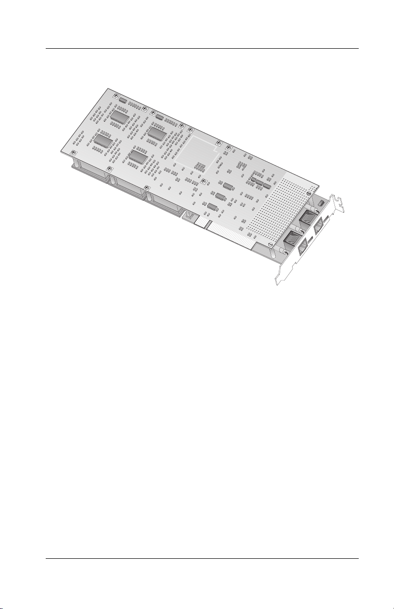
Figure 1-1. 5536-DM RAS Communications Controller
Hardware Overview
Following are the standard hardware features of the
communications controller:
• Modular design with a CPU mother board and one
WAN daughtercard
• ISDN compatibility in North America, Europe,
Australia, and Japan
• Compliance to all industry standards and specifications
(FCC part 15 class A and part 68, CE class A, IEC950)
5536 PRI RAS Communications Controller Users Guide 3
Page 24

Hardware Overview
• CPU mother board:
• Internal Channel Service Unit (CSU) to enable a direct
• RAS support for ISDN channels, including ISDN B
• Three expansion slots allowing the addition of up to 18
• Digital modem extension cards (5536-DM modules)
– RISC processor 32-bit PowerPC 403 GCX at
66 MHz
– 32-bit local bus at 33 MHz
– 8-Mbyte DRAM memory
– 512 KB Flash EEPROM for boot code and modem
firmware
– PCI 2.1-compliant master/target bus interface
connection to a North American T1 line
channels associated with digital modems:
– On the single-port board: RAS support for up to 30
B channels and 1 D channel (Europe and Australia)
or 23 B channels and one 1 channel (United States
and Japan)
– On the dual-port board: RAS Support for up to 60 B
channels and 2 D channels (Europe and Australia) or
46 B channels and 2 D channels (United States and
Japan)
digital modems on digital modem extension modules
available, with six digital modems in each module,
implemented with Rockwell CSM/3 chips
DM modules can be pre-installed or installed as
upgrades, depending on customers’ needs. For
information about installing DM modules, see the Read
Me First documentation included with the DM module
package.
4 Interphase Corporation
Page 25

Software Overview
The software package supports up to four 5536-DM boards
installed in a system. It handles three types of ports:
• ISDN(x), for ISDN communications using RAS
• DM(x), for digital modem communications using RAS
• COM(x), for digital modem communications using
COM ports
The software package includes drivers, utilities, and a RAS
management tool.
Drivers
The software package includes the following drivers:
• The Base driver for Windows NT is the basic driver
required to support the board.
• The Serial driver manages COM port emulation on the
board. It supports digital modem communications by
enabling ISDN B channels to emulate COM ports. It is
installed with the base driver.
• The RAS support drivers support Microsoft Remote
Access Service. They enable the transport of TCP/IP,
IPX/SPX, and NetBEUI protocols over ISDN and
digital modem lines.
Chapter 1: Introduction
The RAS support driver can also extract the security
information included in the packets exchanged at the
beginning of the communication, during the
authentication phase, and provide it to the SecurID
support driver. The PPP authentication protocols
supported for SecurID are PAP, CHAP, and MS-CHAP.
There are two types of RAS support drivers:
– RAS support driver for ISDN communications
5536 PRI RAS Communications Controller Users Guide 5
Page 26

Software Overview
Utilities
The software also includes the following utilities, which are
installed along with the base driver:
– RAS support driver for digital modem
communications
• The SecurID support driver submits, in coordination
with the SecurID support service, the security
information to the ACE/Server through the local
ACE/Agent, and gives the authentication result back to
the RAS support driver, which will either carry on the
connection or abort it.
New PIN and Next Tokencode modes are not
supported.
• The WAN Adapters Setup utility enables you to manage
the board’s firmware and hardware properties.
• The Digital Modem Monitor utility enables you to
monitor the board’s digital modem connections.
• The SynWatch utility enables you to track connections
and data traffic on ISDN channels.
• The LoopTest utility enables you to check the ISDN
line.
• The Line Test utility enables you to set port modes (with
your Telco’s agreement) if you need to do low-level
testing because of line trouble at installation.
• The Line Status utility enables you to diagnose network
connection problems.
6 Interphase Corporation
Page 27

Chapter 1: Introduction
RAS Management Tool
The Virtual Motion Remote Access Manager Suite, by
Acotec, is bundled with the software package. The Remote
Access Manager Suite includes a set of resource management,
access control, and usage accounting tools to help network
administrators and Internet Service Providers manage
Microsoft Windows NT dial-up RAS servers.
The Remote Access Manager Suite is a client/server
application with three components: an administrator program,
a RAS port manager program, and a RAS port monitoring
program. You can select to install the Remote Access Manager
components on a RAS server machine when you install a RAS
support driver.
The Remote Access Manager Suite provides the following
capabilities:
• RAS Login Control prevents multiple users from
logging in with the same dial-up account and limits the
multi-link RAS connections remote users can establish.
• RAS Port Access Control grants specified user groups
access to particular communications ports.
• Port Session Control sets maximum idle and session
connect times for RAS server communications ports.
• Port Resource Management limits the connect time
allotted to users over a specified time interval.
• Static IP Address Port Assignment associates a static IP
address with a specific RAS communications port.
• RASView provides real-time monitoring of RAS ports
and provides alerts for defined RAS server events.
• RAS usage accounting, reporting, and event logging
functions detail users RAS sessions.
5536 PRI RAS Communications Controller Users Guide 7
Page 28

RAS Support Overview
The Remote Access Manager Suite requires Windows NT 4.0
and the Windows NT Service Pack 3 or higher. For detailed
information about the suite, see the Acotec Virtual Motion
Remote Access Manager documentation included in PDF
format on the 5536-DM RAS installation CD.
RAS Support Overview
The communications controller uses Microsoft RAS to
provide remote user connections over ISDN lines. RAS
enables the transport of TCP/IP, IPX/SPX, and NetBEUI
protocols.
RAS supports all of the mainstream networking clients,
including the following:
• Windows for Workgroups
• LAN Manager
• Windows 95
• Windows NT Workstations
• Windows NT Servers
• UNIX
• Macintosh
• NetWare
• OS/2-based clients.
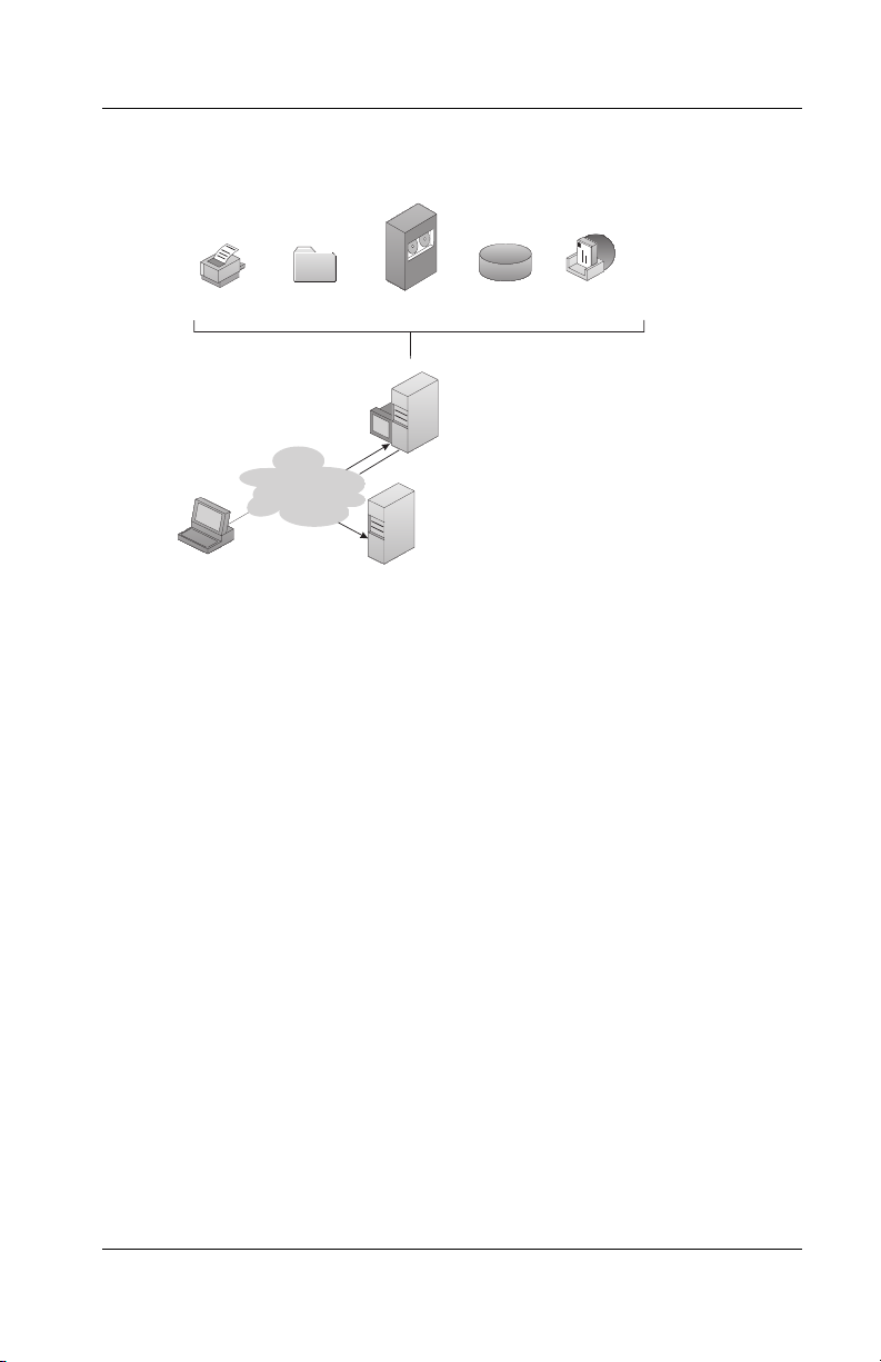
RAS connection enables all services typically available to a
LAN-connected user (including file- and print-sharing,
database access, and messaging), as shown in the following
illustration:
8 Interphase Corporation
Page 29
Chapter 1: Introduction
Printing
Remote Client
File sharing
ISDN
Host access
Internet Service
Provider
Database
Remote Access Server (Windows NT Server)
Up to 46 simultaneous clients (60 for Europe)
Figure 1-2. RAS Features
SecurID Support Overview
Security for connections to RAS Server is usually provided
using the PPP authentication protocols (PAP, CHAP, or MSCHAP) processed by Microsoft RAS. To grant access to the
server, remote clients must supply static identity and
password. Since these parameters can easily be guessed or
hacked, Security Dynamics proposes a stronger security
system based on a Personal Identification Number (PIN) in
combination with a randomly generated passcode. The
passcode is received from a SecurID token (credit-card sized
electronic device), but changes every 60 seconds. Therefore,
authentication parameters for a connection are not available
for a later connection.
E-mail
Scheduling
5536 PRI RAS Communications Controller Users Guide 9
Page 30
SecurID Support Overview
The present documentation does not describe how to install
and setup your ACE/Server and/or ACE/Agent. Please refer to
the Security Dynamics documentation to properly configure
these applications.
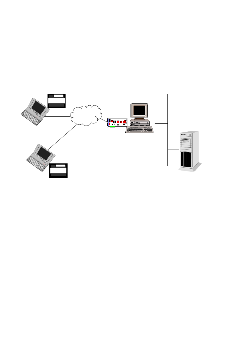
56237
SECURID
ISDN
12345
SECURID
ENTIA
NT Server / RAS
SecurID Agent
ACE/Server
Figure 1-3. SecurID configuration
The SecurID support included in the 5536-DM RAS software
provides stronger security for RAS access: ISDN RAS access
only, digital modem RAS access only, or both.
The software on the client side remains unchanged. When a
remote client wants to connect to the RAS server, the client
runs the Dial-p utility. In the User name field, he inserts his
Windows NT username followed by his SecurID username
(that is the default login name in the ACE/Server's user
configuration) and the current passcode, all fields separated by
a separator character (@ by default) such as:
NTuserid@SDuserid@SDpasscode
The user also provides the Windows NT password, as usual.
10 Interphase Corporation
Page 31

Chapter 1: Introduction
Figure 1-4. DialUp Dialog Box for SecurID Connection
The User name field consists of:
• The name of the RAS user as declared on the server side
(
NTuserid)
• The name of the owner of the SecurID token as declared
in the default login name field on the SecurID server
(
SDuserid)
• The passcode received from the SecurID token at the
time of the connection startup (
SDpasscode). The
passcode value changes every 60 seconds and its
structure depends on the token type.
During the authentication phase with RAS Server, the RAS
support driver extracts the security information and submits it
to the ACE/Server through the SecurID driver and service, and
the local ACE/Agent.
5536 PRI RAS Communications Controller Users Guide 11
Page 32

Minimum System Requirements
• If the ACE/Server grants the access, the communication
can continue with the Windows NT authentication
phase.
• If the ACE/Server refuses the access, the
communication is immediately broken. When the
connection is untrusted because of the passcode end-ofdelay, the remote client is not especially notified: the
failure is a connection failure. It is the client’s
responsibility to start the connection again.
The RAS support driver can manage secured multilink
connections as well. The SecurID authentication is processed
only for the primary link.
All the SecurID authentication successes or failures are
registered in the Windows NT Event log.
Minimum System Requirements
Following are the minimum system requirements for using this
board with Microsoft Remote Access Service (RAS):
• Intel
• PCI Bus architecture conforming to PCI Local Bus
• Pentium processor at 133 MHz or faster
• 64 MB RAM (possibly 128 MB or more, depending on
• Hard disk with 6 MB free
®
system running Windows NT Version 4.0
Specification Revision 2.1
your RAS configuration and usage)
• CD-ROM drive
• Single PRI version: One functional ISDN primary rate
interface for each board
• Dual PRI version: One or two functional ISDN primary
rate interfaces for each board
12 Interphase Corporation
Page 33

Chapter 1: Introduction
• Microsoft Windows NT Service Pack 3 or higher
required for Acotec Remote Access Manager Suite
bundled with the software
5536 PRI RAS Communications Controller Users Guide 13
Page 34

Minimum System Requirements
14 Interphase Corporation
Page 35

2Installing the
Overview
You can install the communications controller board in any
suitable PCI expansion slot. To install the board, follow these
basic steps:
1. Verify that the system meets minimum requirements.
2. Inspect the board.
3. Install the board in a host expansion slot.
4. Connect the board to an MVIP Bus, if required.
The tools required are a grounding strap and a #1 Phillips head
screwdriver. Both are included in the product packaging.
NOTE
Refer to the users manual that came with your personal
computer for additional detailed installing instructions.
Hardware
2
Verifying Minimum Requirements
Before installing this board, verify that your system meets the
minimum requirements described in Minimum System
Requirements on page 12.
5536 PRI RAS Communications Controller Users Guide 15
Page 36

Inspecting the Board
Inspecting the Board
Before installing the communications controller board in your
computer, visually inspect it for any damage that might have
occurred during shipment from the factory.
CAUTION
The board is packed in an antistatic bag to protect it
during shipment. Keep the board in its protective
antistatic bag until you are ready to install it in the host
computer. To prevent damage to the board due to
electrostatic discharge, wear a grounding strap and
handle the board only by its edges. Do not touch its
components or any metal parts other than the faceplate.
1. Open the shipping container and carefully remove its
contents.
2. Inspect each item for damage. If you find any omissions
or damage, contact your supplier and the carrier (for
example, UPS or Federal Express) that delivered the
package.
16 Interphase Corporation
Page 37

Installing the Board
WARNING
Your computer operates at voltages that can be lethal.
Follow all cautions and warnings in this installation
procedure, both to protect yourself and prevent damage
to your computer. Use only tools with nonconductive
handles, or tools coated with, covered with, or made with
nonconductive materials. Nonconductive materials are
materials that do not conduct electric current, such as
plastic, rubber and fiberglass.
With a grounding strap connected to your wrist or ankle, do the
following to install the board:
Chapter 2: Installing the Hardware
5536 PRI RAS Communications Controller Users Guide 17
Page 38
Installing the Board
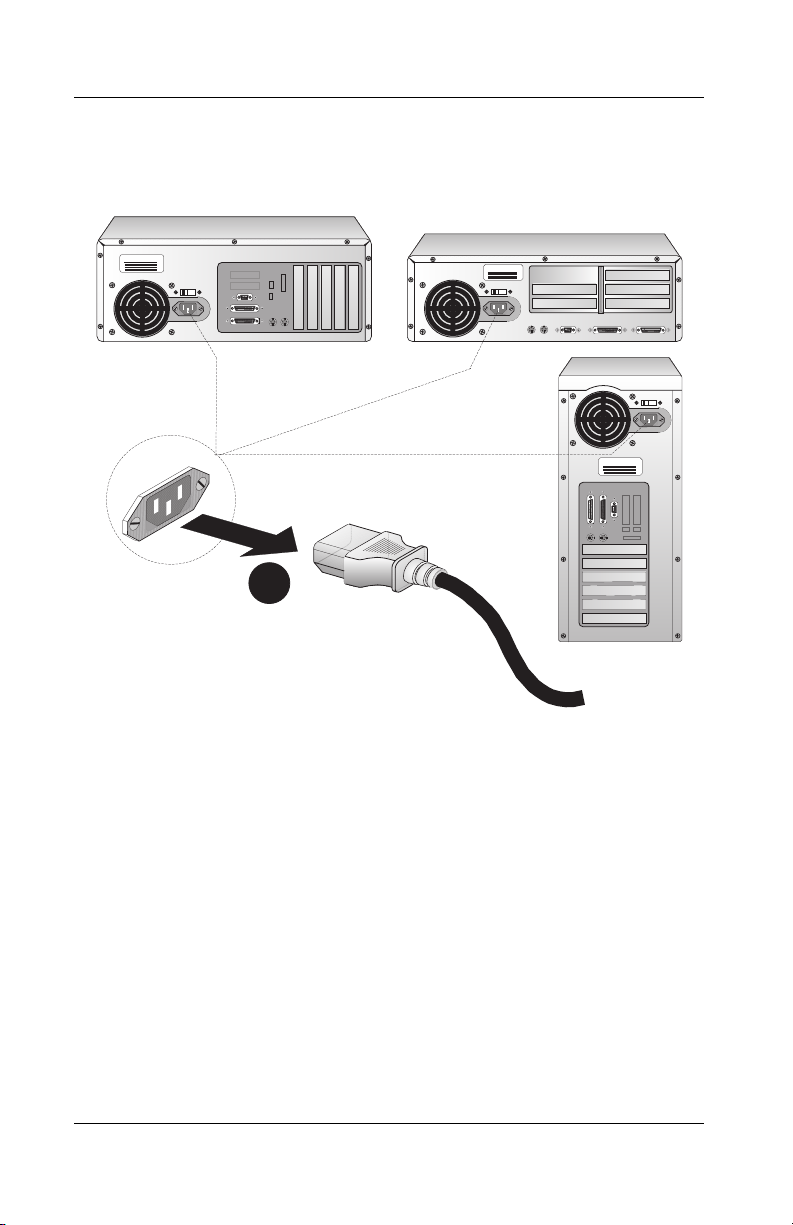
1. Turn off the computer’s power switch, and unplug the
unit from its power source.
Abcdefg Computers
Abcdefg Computers
Abcdefg Computers
1
Figure 2-1. Unplugging the Computer
2. Disconnect all cables connected to the main system
unit, and remove the computer cover according to the
manufacturer’s instructions.
18 Interphase Corporation
Page 39

Chapter 2: Installing the Hardware
2
2
2
Figure 2-2. Removing the Computer Cover
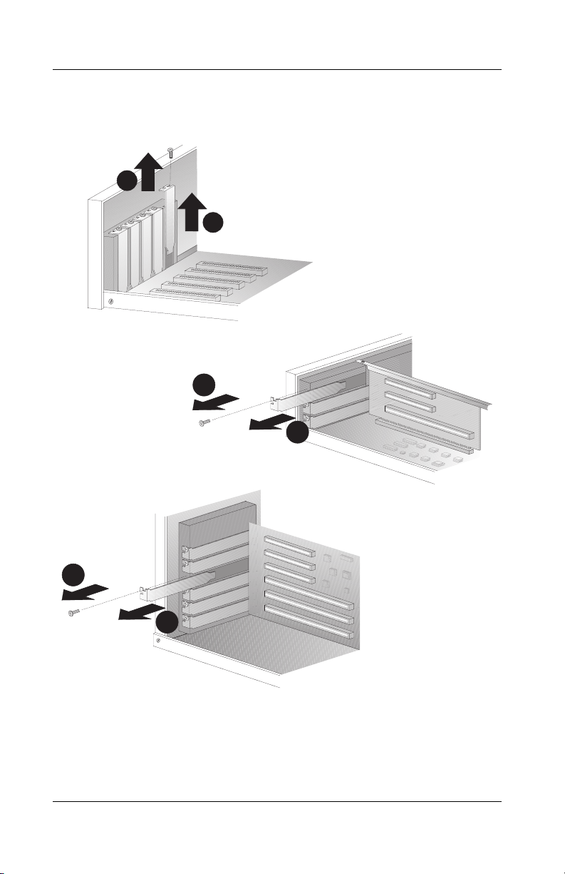
3. Locate a suitable PCI expansion slot, and remove the
screw that attaches the expansion plate to the computer.
Save the screw for Step 6.
This board is a full-length PCI add-on card. Choose a
slot in which the board will not be in contact with other
elements of the motherboard, such as memory modules,
connectors, or the host processor’s heat sink.
CAUTION
If you are installing on an MVIP bus, see Connecting to an
MVIP Bus on page 22 before continuing.
5536 PRI RAS Communications Controller Users Guide 19
Page 40
Installing the Board
4. Remove the expansion plate.
3
4
3
4
3
4
Figure 2-3. Removing the Expansion Plate
20 Interphase Corporation
Page 41

Chapter 2: Installing the Hardware
5. Carefully remove the board from its antistatic bag, and
position the board in the PCI expansion slot. Align the
board’s connector pins with the slot’s receptacle; then
press gently but firmly on the board to seat it in the slot.
6. Attach the board with the screw removed in step 3.
6
5
5
6
5
6
Figure 2-4. Inserting the Board
5536 PRI RAS Communications Controller Users Guide 21
Page 42

Connecting to an MVIP Bus
7. Continue as follows:
– If you want to connect the board to other 5536 WAN
boards in the computer, skip to the next section,
Connecting to an MVIP Bus.
– Otherwise, replace the computer cover according to
the manufacturer’s instructions. Then connect the
board to the line, as described in Connecting to the
Line on page 27.
CAUTION
Keep the computer closed while the board is running, so
that the fan works properly and prevents overheating.
Connecting to an MVIP Bus
If you connect multiple 5536 WAN boards in the same
computer to an MVIP bus, and enable the boards’ MVIP bus
connections, the boards can connect to each other. This
connection enables 5536 boards in the same machine to
exchange information through the shared Call Setup
application.
When multiple 5536 WAN boards are connected on an MVIP
bus, one board can pass calls of an unsupported channel type
to another that supports the channel type. For example, an
5536 WAN board without digital modems (and therefore no
support for speech channels) can pass speech calls to an 5536
WAN board with digital modem channels configured to accept
speech calls.
22 Interphase Corporation
Page 43

Chapter 2: Installing the Hardware
For optimal electrical signal quality on the MVIP ribbon cable,
you must place the MVIP boards in a specific order (depending
on the number of connections) and electrically terminate two
MVIP clock signals, as described in the following topics.
MVIP Electrical Termination Requirements
For systems with five or fewer MVIP Bus connections and less
than 90 pF load on the clock lines, it is adequate to do the
following:
1. Place the circuit board that is the master clock source at
one end of the cable.
2. Electrically terminate the MVIP Bus only on the circuit
board located at the other end of the cable.
NOTE
An 5536 board is generally the master clock source
because it is connected to the network. In this case, place
an 5536 board at one end of the cable, and do not
electrically terminate the bus on this board.
On systems with more than five MVIP Bus connections or
more than 90 pF of load on the clock lines, both ends of the
cable must be electrically terminated. No other boards should
be electrically terminated.
5536 PRI RAS Communications Controller Users Guide 23
Page 44

Connecting to an MVIP Bus
Configuring MVIP Electrical Termination
If this is the last board in a multiple MVIP Bus configuration,
it requires electrical termination in the MVIP Bus. To provide
the required electrical termination, place two jumpers on the
two 2-pin connectors located next to the MVIP connector.
Each jumper must be inserted perpendicular to the printed
circuit board, as shown in the following figure:
Figure 2-5. Electrically Terminating the MVIP Bus
If the board does not need to be electrically terminated, do not
place any jumpers on the 2-pin connectors.
24 Interphase Corporation
Page 45

Chapter 2: Installing the Hardware
Modem Connection LEDs
The 5536-DM RAS provides an LED for each modem
included on the board (for example, 12 LEDs for 12 modems).
These LEDs turn on when a modem has established a
connection on the MVIP Bus. They turn off when the modem
has interrupted the connection.
Completing the MVIP Bus Connection
To create a dedicated interconnection among MVIP boards,
connect a ribbon cable to the 40-pin, double-row, right-angled
headers on the top edges of the boards.
After you finish connecting the board to the MVIP Bus, finish
the remaining steps in the Installing the Board section.
5536 PRI RAS Communications Controller Users Guide 25
Page 46

Connecting to an MVIP Bus
26 Interphase Corporation
Page 47

3Connecting to the
Overview
The methods for connecting your 5536 board to the line
depend on whether your carrier provides a T1/PRI line or an
E1/PRI line.
This chapter provides the following information required to
connect your board to the line:
• Connection methods and requirements for connecting
• Connection methods and requirements for connecting
• Summary of steps to connect the board to the network
If your carrier provides a T1 line, continue to the next section.
If your carrier provides an E1 line, skip to E1/PRI Line on page
32.
to a T1/PRI line
to an E1/PRI line
Line
3
T1/PRI Line
When you connect the board to a T1/PRI line, first determine
the appropriate connection method, cabling requirements, and
link requirements.
Connection Methods
If the distance to your carrier is less than 655 feet or 200
meters, you can connect the board in a DSX1 (short haul)
configuration directly to the T1/PR1 line.
5536 PRI RAS Communications Controller Users Guide 27
Page 48

T1/PRI Line
If the distance is more than 655 feet or 200 meters (up to 6200
feet or 1.8 kilometers), you must connect the board in a DS1
(long haul) configuration. In the DS1 configuration, a Channel
Service Unit (CSU) must translate the short haul DSX1
interface to support the longer distance. The 5536-DM RAS
board includes an internal CSU, which enables it to connect
directly to the T1/PRI line in a DS1 configuration.
Connecting Directly to the Line
Direct connection is subject to constraints imposed by FCC
rules and by your partner carrier. To see if you can connect
directly to the interface, and for more information about direct
connection constraints, contact your carrier.
WARNING
To avoid harming the WAN, contact your carrier for
approval before connecting the board directly to the line.
CAUTION
In accordance with FCC Rules, Part 68.218 (b), you must
notify the telephone company prior to disconnecting the
board from the line or turning off the power to the board’s
host system. Without this prior notification, the carrier
might temporarily discontinue your T1/PRI service.
28 Interphase Corporation
Page 49

Chapter 3: Connecting to the Line
Connecting Directly in a DSX1 Configuration
You can connect the board directly to the T1/PRI line without
using a CSU if the distance to your carrier is less than 655 feet
or 200 meters. The line will be in a DSX1 configuration, as
shown in the following illustration:
Less than 655 feet (200m)
WAN Adapter
Telco
Figure 3-1. Direct DSX1 Connection to the Line
Connecting Directly in a DS1 Configuration
If the distance to your carrier is up to 6200 feet (1.8
kilometers), you can connect directly to the T1/PRI line with
the board’s internal CSU activated. The line will be in a DS1
configuration, as shown in the following illustration:
Up to 6200 feet (1.8 km)
WAN Adapter
Telco
Figure 3-2. Direct DS1 Connection with Internal CSU
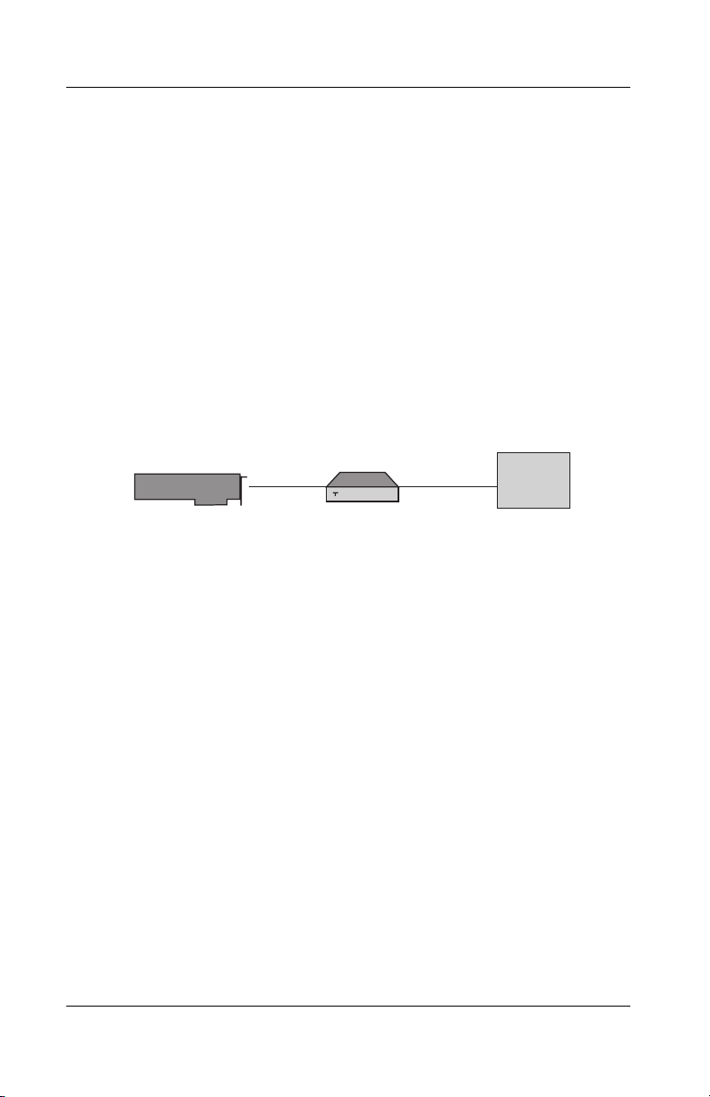
Connecting Through an External CSU to the Line
If you do not use the board’s internal CSU to connect to the
T1/PRI line in a DS1 configuration, you can connect the board
to an external CSU that connects to the metallic T1/PR1
interface. (You might want to use this method if the distance to
5536 PRI RAS Communications Controller Users Guide 29
Page 50

T1/PRI Line
your carrier exceeds 6200 feet or 1.8 kilometers but is less than
6855 feet or 2.0 kilometers.) The following illustration shows
a connection to the T1/PRI line through an external CSU:
Less than 655 feet (200m)
WAN Adapter Telco
Up to 6200 feet (1.8 km)
CSU
Figure 3-3. DS1 Connection Through an External CSU
WARNING
To avoid harming the WAN, you must first contact your
carrier for approval before connecting the CSU to the line.
CAUTION
In accordance with FCC Rules, Part 68.218 (b), you must
notify the telephone company prior to disconnecting the
CSU from the line or turning the CSU’s power off. Without
this prior notification, the carrier might temporarily
discontinue your T1/PRI service.
30 Interphase Corporation
Page 51

Chapter 3: Connecting to the Line
T1/PRI Cabling Requirements
The cable between the board and the carrier or the CSU must
meet the following standard T1 attenuation and transmission
requirements:
• 100 Ohms
• Two twisted pairs, category 3 or higher
• Maximum length: 655 feet (200 m) without a CSU, or
6200 feet (1800 meters) with a CSU
Measure and record the actual cable length between the board
and the carrier or the CSU. You will need this information
when you configure the line profile parameters.
The cable must include an RJ48C plug at the end dedicated to
the WAN board. It must also provide the appropriate plug or
cabling system at the end connected to the carrier or CSU. See
Connector Pinouts on page 34 and relevant carrier or CSU
documentation for more information.
T1 Link Requirements
If the board connects to the T1/PRI line, the board and CSU
must be configured with several common parameters to
interoperate. The board’s T1 parameters are set as follows:
• Line coding: B8ZS
• Frame format: ESF (Extended Super Frame)
• Line I/O impedance: 100 Ohm ± 5%
5536 PRI RAS Communications Controller Users Guide 31
Page 52
E1/PRI Line
WAN Adapter
Telco
E1/PRI Line
When you connect the board to an E1/PRI line, first determine
the appropriate connection method, cabling requirements, and
link requirements.
Connection Method
Generally, your E1/PRI carrier provides a Network
Termination 1 (NT1) device to interface between the WAN
board and the metallic interface of the WAN. You need to
connect the WAN board to the NT1, as shown in the following
illustration:
WAN Adapter
NTI
Telco
Figure 3-4. Connection Through an External NT1 Device
E1/PRI Cabling Requirements
The cable between the board and the NT1 must meet the
following standard E1 attenuation and transmission
requirements:
• 120 Ohms
• Two twisted pairs, category 3 or better
• Maximum length: 200 m (655 feet)
The cable must include an RJ48C plug at the end dedicated to
the WAN board. It must also provide the appropriate plug or
cabling system at the end dedicated to the NT1. See Connector
Pinouts on page 34 and your NT1 documentation for details.
32 Interphase Corporation
Page 53

Chapter 3: Connecting to the Line
E1 Link Requirements
If the board connects to the E1 line, the board and NT1 must
be configured with several common parameters to
interoperate. The board’s E1 parameters are in accordance
with the IUT-T I 431 recommendation, as follows:
• Line coding: HDB3, according to IUT-T G.703
• Frame format: according to IUT-T G.704
• CRC4 to Non-CRC4 operation: according to
IUT-T G.706 An.B
• Line I/O impedance: 120 Ohm ± 5%
5536 PRI RAS Communications Controller Users Guide 33
Page 54
Connector Pinouts
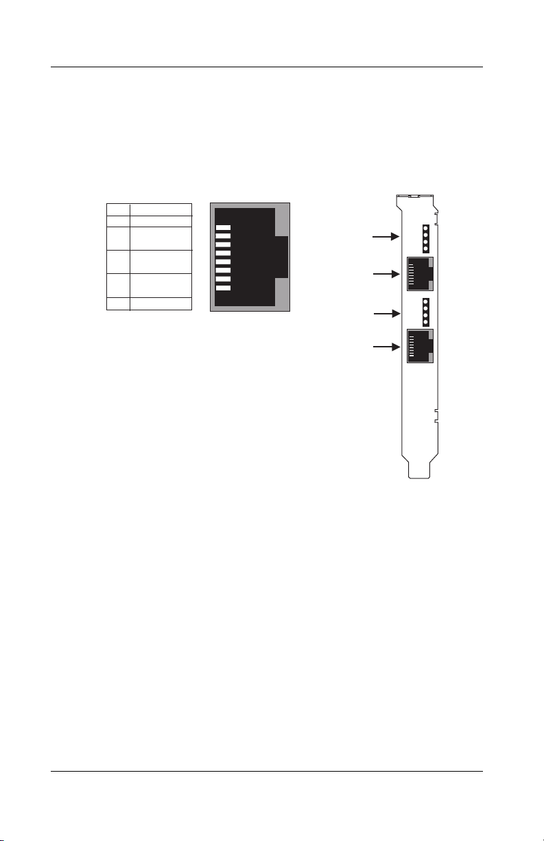
Connector Pinouts
The following illustration of the board’s faceplate shows the
board’s connectors and connector pins:
Signal
Pin
8
7
6
Tx out (tip)
5
Tx out (ring)
4
3
Rx in (tip)
2
Rx in (ring)
1
RJ48C Pinout
8
1
LEDs 1, 2, 3 & 4
(Port #0)
Port #0
(RJ48C)
LEDs 5, 6, 7 & 8
(Port #1)
Port #1
(RJ48C)
Figure 3-5. Faceplate and Connector Pinouts
The board’s connectors follow the RJ48C specification.
For each connector, four LEDs display the status of the link (as
described in Interpreting LEDs on page 118).
34 Interphase Corporation
Page 55

Connecting to the Network
WARNING
Before connecting the cable, read Telephone Lines
Unsafe Voltages in the Safety Precautions section at the
front of this manual.
With the board installed, you are ready to connect to the
network, as follows:
1. Obtain the cable required for your type of connection, as
described in T1 Link Requirements on page 31 or
E1/PRI Cabling Requirements on page 32.
2. Attach the appropriate RJ48C-compliant connector to
the board.
Chapter 3: Connecting to the Line
3. Reconnect the power cable and turn on the machine.
After connecting to the network, install the drivers. See
Installing the Software on page 37.
5536 PRI RAS Communications Controller Users Guide 35
Page 56

Connecting to the Network
36 Interphase Corporation
Page 57

4Installing the
Overview
This chapter describes the procedures for installing and setting
up your 5536 software on Microsoft Windows NT 4.0
workstations. Use this process to install the Base driver (along
with the Serial driver and utilities), the ISDN RAS support
driver, the Digital Modem RAS support driver, the SecurID
support driver and service, and the Acotec Virtual Motion
Remote Access Manager Suite. This chapter also explains how
to remove 5536 software, if required.
To install and set up the software, follow these basic steps:
1. Verify that your system meets minimum requirements.
2. Install the Base driver, with accompanying software,
3. Set up WAN card and port properties.
Software
and the appropriate RAS support driver(s).
4
4. Set up RAS support properties for the installed RAS
driver(s).
5. Set up ISDN B and Digital Modem channels as RAS
ports.
6. If you want to use Acotec Virtual Motion RAS
management services on the computer, install Remote
Access Manager Suite components.
7. Complete the installation to make driver settings take
effect.
5536 PRI RAS Communications Controller Users Guide 37
Page 58

Verifying Minimum Requirements
Review the Read Me text file on the 5536-DM RAS
installation CD before installing the software. It contains
information about the files included on the CD. Also, if Read
Me First documentation is included in your installation kit,
review it for information about changes and updates made to
this Users Guide after the print date.
In addition, if you plan to install the Remote Access Manager
Suite, review the Acotec Virtual Motion PDF documentation
included on the installation CD before starting the installation.
NOTE
The 5536-DM RAS is named 5536 in the software
installation and configuration dialogs. The name appears
as 5536-1P-PRI for the single-port version or as 5536-2P-
PRI for the dual-port version.
Verifying Minimum Requirements
If you have not already done so, verify that your system meets
the minimum requirements described in Minimum System
Requirements on page 12.
38 Interphase Corporation
Page 59

Installing the Drivers
NOTE
Before you start, make sure the communications
controller is installed in your machine, and that you are
logged on with administrator rights to the Windows NT 4.0
system.
To install the appropriate drivers:
1. From the Start menu, select Settings, and then Control
Panel. Then double-click the Network icon, and select
Chapter 4: Installing the Software
5536 PRI RAS Communications Controller Users Guide 39
Page 60
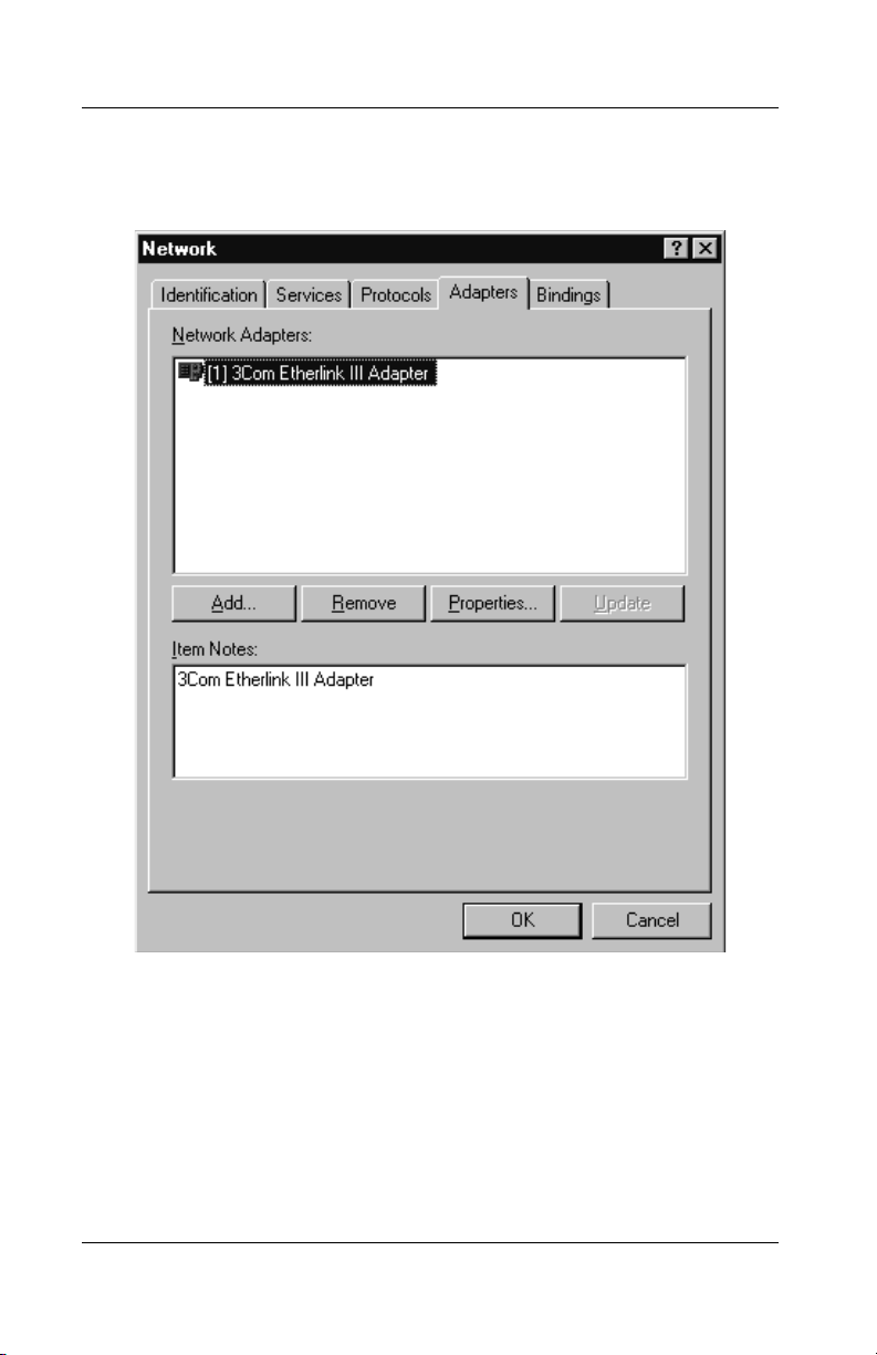
Installing the Drivers
the Adapters tab to display the Network Adapters
dialog box:
Figure 4-1. Network Adapters Dialog Box
2. Click Add to begin loading the drivers.
40 Interphase Corporation
Page 61
Chapter 4: Installing the Software
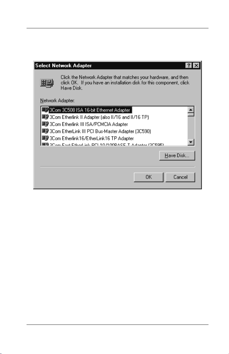
The system creates a driver list in the Select Network
Adapter dialog box:
Figure 4-2. Network Adapters List
3. Click Have Disk.
The Insert Disk dialog box appears, prompting you to
insert the disk and identify the file location:
5536 PRI RAS Communications Controller Users Guide 41
Page 62

Installing the Drivers
4. Insert the installation CD-ROM, and change the
5. The Select OEM Option dialog box appears, listing
Figure 4-3. Insert Disk Dialog Box
installation path to
the CD-ROM drive—for example,
[drive]:\5536 (where [drive] is
D:\5536.) Then
click OK.
available Interphase RAS Support drivers:
Figure 4-4. Select OEM Option Dialog Box
42 Interphase Corporation
Page 63

Chapter 4: Installing the Software
You can install the 5536 Digital Modem RAS Support
driver, the 553x ISDN RAS Support driver, or both
drivers, depending on your needs. However, you can
select only one driver to install at a time.
6. Select the RAS Support driver you want to install at this
time, and click OK.
– Next, if you are installing the first RAS support
driver, the Interphase 553X Base driver dialog box
appears. Continue to Step 7.
– If you are installing the second RAS Support driver,
the RAS Support General dialog box appears. Go to
Setting Up RAS Support Properties on page 50.
7. The Base Driver dialog box prompts you to begin
installation:
Figure 4-5. Base Driver Installation
If needed, change the default installation path in the
Copy To field to the desired path name.
8. Click Continue to install the Base driver and the first
selected RAS Support driver.
5536 PRI RAS Communications Controller Users Guide 43
Page 64

Setting Up Card and Port Properties
The installation program copies product files to
installation directory, and creates a program group in
the Windows NT Start menu.
To continue the software installation, set up the card and port
properties as described in the next section, Setting Up Card
and Port Properties.
Setting Up Card and Port Properties
After the initial driver software is installed as described in
Installing the Drivers, the WAN Adapters Setup dialog box
appears:
Figure 4-6. WAN Adapters Setup Dialog Box
44 Interphase Corporation
Page 65

Chapter 4: Installing the Software
This dialog box enables you to set up 5536 firmware and
hardware. The board name is displayed in the Cards section.
NOTE
If the Cards list is empty, the board might not be properly
installed. See Problems and Possible Solutions on page
123 for information about correcting the problem.
Use the Cards section to do the following tasks:
• If your board is connected to an MVIP Bus, enable the
MVIP bus connection.
• Set up ISDN port properties.
Configure ISDN port properties for both ISDN and
Digital Modem RAS Support drivers.
• If you plan to install the Digital Modem RAS Support
driver, set up digital modem port properties. Set up
digital modem and ISDN port properties at this point
(regardless of which driver you selected first).
Enabling the MVIP Bus Connection
If your board is connected to an MVIP Bus, enable the Bus
connection as follows:
1. In the Cards section of the WAN Adapters Setup dialog
box, select the board and click the Properties button.
5536 PRI RAS Communications Controller Users Guide 45
Page 66

Setting Up Card and Port Properties
The Card Properties dialog box appears:
Figure 4-7. Card Properties Dialog Box
2. Select the MVIP Bus connected field (in the Bus
section) by clicking on the checkbox.
3. Click OK to save the connection and return to the WAN
Adapters Setup dialog box.
Configuring ISDN Port Properties
ISDN port properties must always be configured for both
Digital Modem and ISDN RAS support drivers. Configure
ISDN port properties as follows:
1. In the Cards section of the WAN Adapters Setup dialog
box, select the ISDN PRI port you want to configure
and click Properties.
The ISDN PRI Port Properties dialog box appears:
46 Interphase Corporation
Page 67
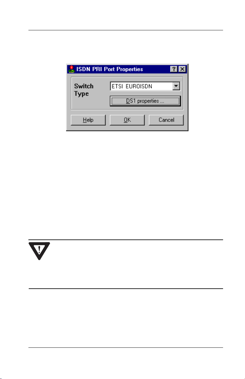
Chapter 4: Installing the Software
Figure 4-8. ISDN PRI Port Properties
2. Depending on your geographic location and other
considerations, change the default switch type and/or
other parameters, as needed.
If you selected a North American switch type, use the
DS1 properties button to activate the board’s internal
CSU for port connections.
For detailed information about ISDN PRI port
properties, see Setting Up ISDN Port Properties on
page 80.
CAUTION
You must select the same switch type for all ports on a
single board. Otherwise, the ports might not function
properly.
3. When you finish the port setup, click OK.
The WAN Adapters Setup dialog box reappears.
5536 PRI RAS Communications Controller Users Guide 47
Page 68
Setting Up Card and Port Properties
4. If the board has dual ISDN ports, repeat Steps 1 through
3 to configure the remaining ISDN PRI port.
Next, continue to Configuring Digital Modem Port Properties
if you are (or will be) installing the Digital Modem RAS
Support driver.
If you do not plan to install the Digital Modem RAS Support
driver, or have already configured digital modem port
properties, go to Completing the WAN Setup on page 49.
Configuring Digital Modem Port Properties
If you are installing the Digital Modem RAS Support driver,
configure corresponding digital modem port properties as
follows:
1. In the Cards section of the WAN Adapters Setup dialog
box, select the digital modem port (x Digital Modems,
where x is the number of digital modems on the board),
and click Properties.
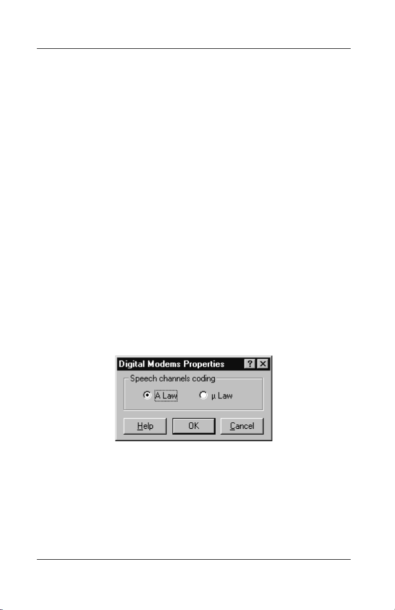
The Digital Modems Properties dialog box appears:
Figure 4-9. Digital Modems Properties Dialog Box
2. Use this dialog box configure the analog-to-digital
speech channels coding law according to the geographic
region.
– For Europe and Australia, select A Law.
48 Interphase Corporation
Page 69
Chapter 4: Installing the Software
– For North America and Japan, select µ Law (Mu
Law).
3. Click OK.
If you have not yet configured the board’s ISDN port
properties, do so now, as described in Configuring ISDN Port
Properties on page 46. Otherwise, continue to the next topic.
Completing the WAN Setup
When WAN card and port properties are configured as needed,
do the following to complete the WAN setup:
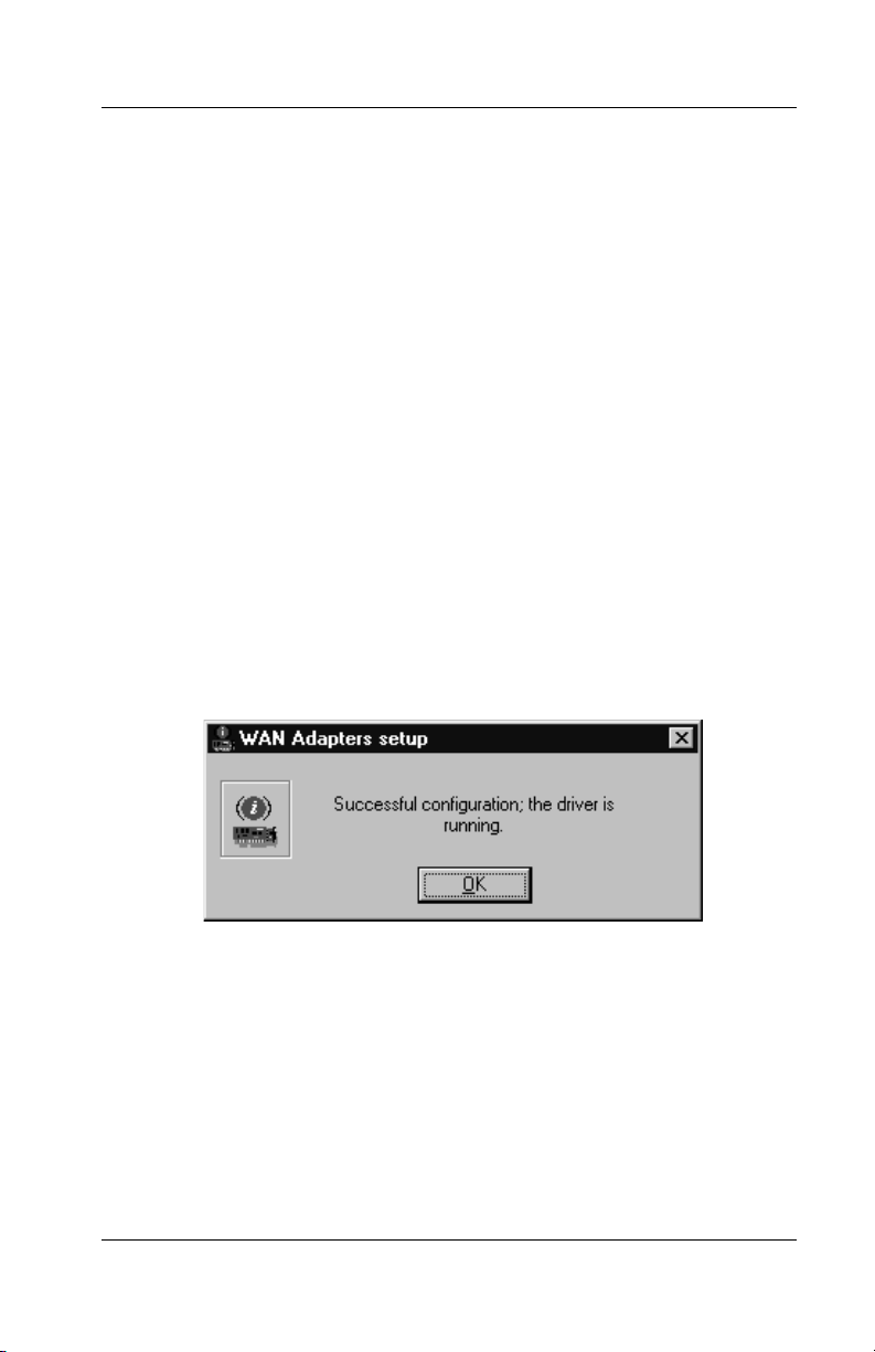
1. Click OK in the WAN Adapters Setup dialog box.
The setup software finds firmware for the board. It
updates the registry and dynamically installs the drivers.
2. When the following message informs you that the driver
is running, click OK.
Figure 4-10. Successful Setup Message
Next, set up RAS support properties for the driver.
5536 PRI RAS Communications Controller Users Guide 49
Page 70
Setting Up RAS Support Properties
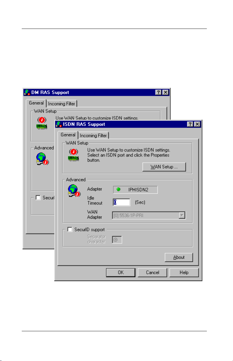
Setting Up RAS Support Properties
After you finish configuring port properties for RAS support
drivers (or after you select the second RAS support driver to
install), the RAS Support General dialog box appears:
Figure 4-11. RAS Support General Properties Dialog Box
50 Interphase Corporation
Page 71

Chapter 4: Installing the Software
For the Digital Modem RAS Support driver, the driver name in
the title bar is 5536 DM RAS Support. For the ISDN RAS
Support driver, the driver name is 553x ISDN RAS Support.
The contents of the dialog box are the same for both drivers.
The RAS support setup is done automatically. The RAS
Support General dialog box enables you verify RAS support
properties for the driver you are configuring.
NOTE
If you need to set up additional card or port properties
before continuing, click the WAN Setup button to access
the WAN Adapters Setup dialog box. Then repeat the
appropriate steps in Setting Up Card and Port Properties
on page 44.
RAS Support dialog boxes and setup procedures are described
in detail in Setting Up RAS Support Properties on page 95.
To complete the RAS Support setup:
1. If needed, change the Idle Timeout value from 0, which
disables the timeout function, to the number of seconds
of inactivity to allow before ending a connection.
2. If needed, check the SecurID support box to enable
additional filtering on SecurID authentication
information and change the Separator character if
necessary.
3. Click OK to confirm the displayed configuration.
One of the following messages appears, depending on
whether RAS is installed on your system:
5536 PRI RAS Communications Controller Users Guide 51
Page 72
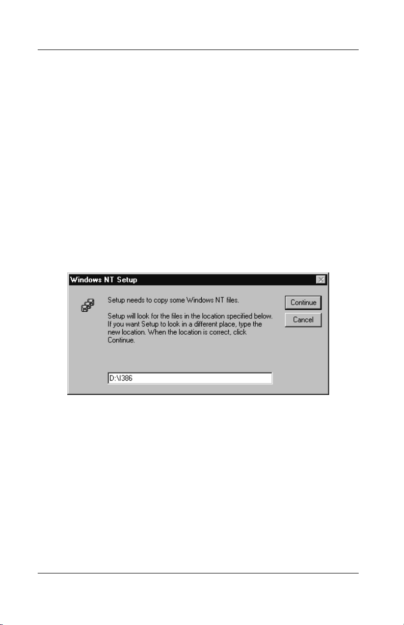
Setting Up RAS Support Properties
– If RAS is not installed, a message informs you that
RAS support setup is complete, and states that
Remote Access Services (RAS) setup must now be
installed.
Click OK. Then continue to step 4.
– If RAS is installed, a message informs you that RAS
support setup is complete, and states that Remote
Access Services (RAS) setup must now be invoked.
Click OK. Then skip to Setting Up Channels as RAS
Ports on page 53.
4. When the following message informs you that Setup
needs to copy Windows NT files, insert the Windows
NT CD:
Figure 4-12. Windows NT Setup Message
5. If you want Setup to find the Windows NT files in a
location other than the default, enter the complete path.
6. Click Continue to complete the RAS installation.
To continue the software installation, set up digital modem or
ISDN channels as RAS ports, as described in the next section,
Setting Up Channels as RAS Ports.
52 Interphase Corporation
Page 73

Chapter 4: Installing the Software
Setting Up Channels as RAS Ports
After you respond OK to the message that Remote Access
Service must be invoked, or click Continue to complete the
RAS installation, either the Remote Access Setup dialog box
or the Add RAS Device dialog box appears. This sequence
depends on whether a RAS device is configured in the
machine.
To set up ISDN or digital modem channels as RAS ports, do
the following:
1. If a RAS device has not yet been added, the Add RAS
Device dialog box appears.
If a RAS device has been added, the Remote Access
Setup dialog box appears. Click Add to display the Add
RAS Device dialog box.
The following illustration shows the Add RAS Device
dialog box:
5536 PRI RAS Communications Controller Users Guide 53
Page 74

Setting Up Channels as RAS Ports
Figure 4-13. Add RAS Device Dialog Box
In the RAS Capable Devices field, the device name
indicates the first available channel type and number.
(For example, ISDN1 - IPHISDN indicates ISDN B
channel 1, or DM1-IPHDM indicates digital modem
channel 1.)
2. Click OK to select the displayed channel to add as a
RAS port. (Or select a different channel and click OK.)
54 Interphase Corporation
Page 75

Chapter 4: Installing the Software
The Remote Access Setup dialog box appears, with the
selected channel listed as a RAS port, as follows:
Figure 4-14. Remote Access Setup Dialog Box
3. Click Configure to set up the port’s connection mode.
The Configure Port Usage dialog box appears:
Figure 4-15. Configure Port Usage Dialog Box
5536 PRI RAS Communications Controller Users Guide 55
Page 76

Setting Up Channels as RAS Ports
4. Select a port usage option, and click OK.
The Remote Access Setup dialog box reappears.
5. To quickly add and configure remaining channels as
RAS ports with the same properties as a configured
port, do the following:
a. Select the port whose properties you want to copy,
and click the Clone button.
The next available channel is added to the port list.
The port usage properties are copied from the
selected port.
b. Click the Clone button repeatedly until you have
configured all the RAS ports you need. (Or until you
receive the message There are no more ports of the
specified type to clone.)
Or to configure the channels’ port usage properties oneby-one, click Add to display the Add RAS Device
dialog box. Then repeat Steps 2 through 4.
6. Do the following to select the network protocols to be
bound to the board:
a. On the Remote Access Setup dialog box, click
Network to display the Network Configuration
dialog box:
56 Interphase Corporation
Page 77

Chapter 4: Installing the Software
Figure 4-16. Network Configuration Dialog Box
For NT Servers, this dialog box includes the Enable
Multilink option. The multilink function allows
multiple digital modem or ISDN B channels to make
one logical network connection. It aggregates B
channels to increase the bandwidth of PPP links.
b. Configure network settings as needed for your
system.
For detailed network configuration information,
click the Help button to access Microsoft’s online
help.
5536 PRI RAS Communications Controller Users Guide 57
Page 78

Setting Up Channels as RAS Ports
c. Click OK to save the network configuration.
d. Depending on the network settings you configured,
several configuration dialog boxes may appear.
Configure additional settings as needed.
e. When the Remote Access Setup dialog box
reappears, click Continue.
f. If you receive prompts to confirm network settings,
respond as needed for your network configuration.
g. If you are installing the first RAS support driver, and
you installed RAS along with the driver, a message
informs you that Remote Access Service has been
successfully installed. It also reminds you to assign
RAS permissions to users.
Click OK to continue.
Next, either the Network Adapters dialog box or the Acotec
Virtual Motion Remote Access Manager Suite Setup dialog
box appears. This sequence depends on whether the Remote
Access Manager Suite has already been installed on your
system.
• If the Acotec Virtual Motion Remote Access
Manager Suite Setup dialog box appears, continue to
the next section, Installing the Remote Access Manager
Suite on page 59.
• If the Network Adapters dialog box appears, do either
of the following, depending on whether you need to
install another RAS support driver.
– If you do need to install another RAS support driver,
install it now.
Return to Step 2 on page 40 of the Installing the
Drivers section, and repeat the installation and
configuration procedures for the second driver.
58 Interphase Corporation
Page 79

Chapter 4: Installing the Software
– If you do not need to install another RAS support
driver, skip to Completing the Software Installation
on page 62.
Installing the Remote Access Manager Suite
The Acotec Virtual Motion Remote Access Manager Suite is
bundled with the 5536-DM RAS software. (For an overview of
the Remote Access Manager Suite, see RAS Management Tool
on page 7.)
The Remote Access Manager Suite Setup program starts
automatically after you install the first RAS support driver. (If
the suite is not installed with the first driver, the Setup program
also starts after you install the second RAS support driver.)
The Remote Access Manager Suite requires Windows NT 4.0
and the NT Service Pack 3 or higher. It includes client and
server components. Before installing the components, review
the Remote Access Manager PDF documentation on the 5536DM RAS installation CD for detailed recommendations.
NOTES
The installation procedure may differ from the steps
described in this section, depending on the options you
select.
If you need to remove application components after
installation, use the Add/Remove Programs function in
the Windows NT Control Panel.
5536 PRI RAS Communications Controller Users Guide 59
Page 80

Installing the Remote Access Manager Suite
To install the Remote Access Manager Suite, do the following:
1. When the Virtual Motion Remote Access Manager
Suite Setup dialog box appears, click Next to continue.
2. On the Acotec License Software Agreement dialog box,
review the agreement and click Yes to accept the terms.
3. On the Choose Components dialog box, select the
programs you want Setup to install, and click Next.
4. On the Enter License Key dialog box, enter the product
license key. (Find the key on the Acotec license page
included in the 5536 product package.) Then click Next.
5. On the Choose Destination Directory dialog box, follow
the instructions to install the Remote Access Manager
Suite in the appropriate directory. Then click Next to
continue (or click Cancel to cancel and exit the
installation).
6. On the Select Logging Type dialog box, select the type
of dial-in session log you want the RAS Port Manager
to create.
– To create a comma-delimited text file with one
record for each RAS session, select Log to
RPMSESS.LOG file. The RAS Port Manager saves
RPMSESS.LOG in the Windows SYSTEM directory on
the RAS server.
– To write the session log to your database manager
using the ODBC interface, select Log using ODBC
datasource. For this logging method, an ODBC data
source must be set up. For instructions, see your
Acotec Remote Access Manager documentation and
ODBC documentation.
7. When you are prompted to restart windows, select No,
I will restart later.
60 Interphase Corporation
Page 81

Chapter 4: Installing the Software
CAUTION
You must finish installing the driver(s) before restarting
the system, or the driver installation will be incomplete.
When the Network Adapters dialog box appears, do either of
the following, depending on whether you need to install
another RAS support driver:
• If you do need to install another RAS support driver,
install it now. Return to step 2 on page 40 of Installing
the Drivers, and repeat the installation and
configuration procedures for the second driver.
• If you do not need to install another RAS support driver,
continue to the next section, Completing the Software
Installation.
5536 PRI RAS Communications Controller Users Guide 61
Page 82
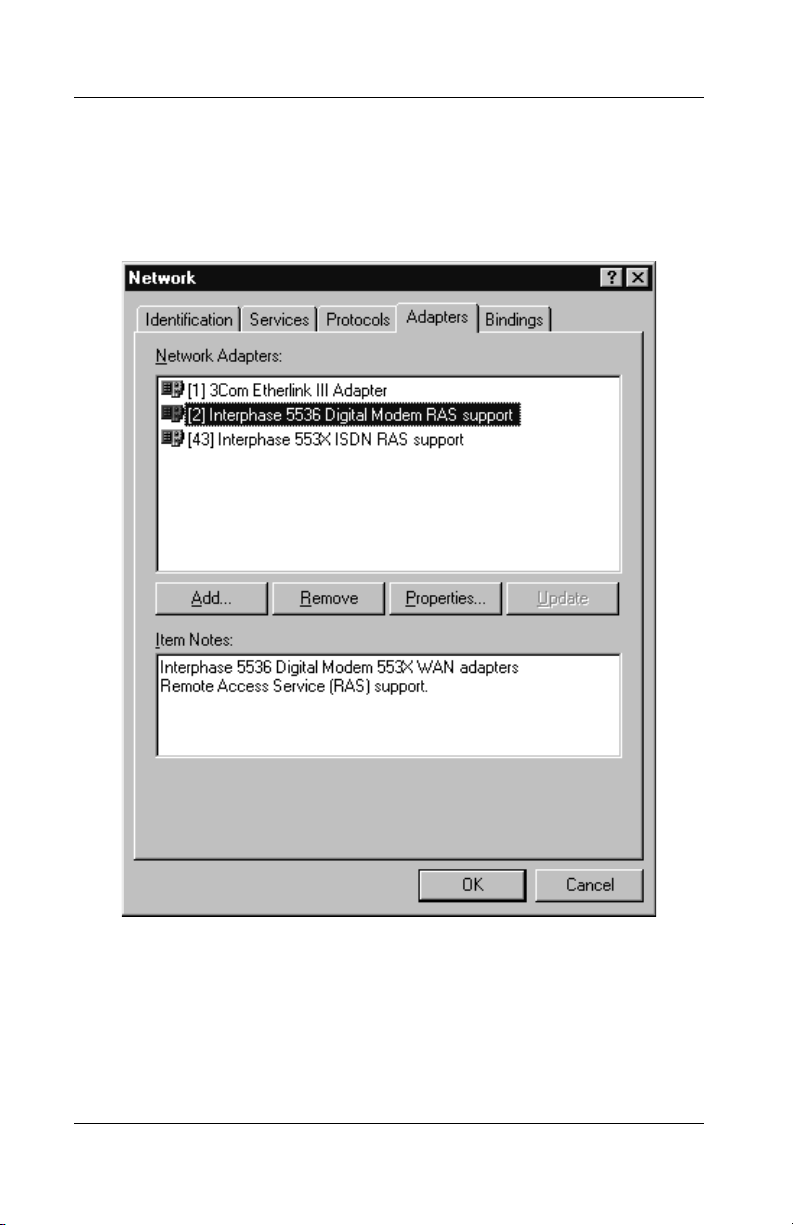
Completing the Software Installation
Completing the Software Installation
After you have configured all of the software you have chosen
to install, the Network Adapters dialog box appears:
Figure 4-17. Network Adapter Drivers List
The Network Adapters list displays the driver(s) you installed
(Interphase 5536 Digital Modem RAS support and/or
Interphase 553X ISDN RAS support).
62 Interphase Corporation
Page 83

Chapter 4: Installing the Software
Do the following to make the installation settings take effect:
1. On the Network Adapters dialog box, click Close.
After the software is fully installed, a message informs
you that you must shut down and restart your computer
before the settings take effect.
2. Continue as follows:
– If the system is a basic Windows NT system, without
the Windows NT Service Pack installed, click Yes to
restart the computer.
– If the Windows NT Service Pack is installed, click
No. Then reinstall the Service Pack. Restart the
system when prompted after you complete the
Service Pack installation.
CAUTION
If the Windows NT Service Pack was installed on the
system after the Windows NT installation, you must
reinstall it before restarting the computer. Service Pack
version 3 or higher is recommended. For installation
information, see the latest available version of your
Service Pack help. If you do not reinstall the Service Pack,
the Remote Access Service may fail to start or
malfunction when connecting ISDN lines.
To determine whether a Service Pack is installed, see
Quick Reference of Common Tasks on page 177.
After the system restarts, check the ISDN line to make sure the
board connects properly, as described in Testing the ISDN Line
on page 154.
5536 PRI RAS Communications Controller Users Guide 63
Page 84

Completing the Software Installation
In addition, you may need to do one or all of the following,
depending on your board and system configuration:
• If your board is connected to an MVIP Bus, the MVIP
Bus connection must be enabled so the software
recognizes the Bus connection. If you need to enable or
disable the Bus connection, see Setting Up Card
Properties on page 77.
• If you need to activate the internal CSU included on the
board, see Editing DS1 Properties on page 82.
• Upon completion of the software installation, eight
Serial driver COM ports are automatically assigned to
the board’s digital modems. If you need to change the
number of COM ports assigned to the digital modems,
see Setting Up Card Properties on page 77.
• If you need to change other firmware, card, or port
properties, see Setting Up WAN Firmware and
Hardware on page 71.
• If you need to change call setup properties for ISDN
RAS support calls, digital modem RAS support calls, or
digital modem serial driver calls, see Setting Up Calls
on page 89.
• If you need to ensure that applications that use Serial
driver COM ports under Windows NT can detect the
board’s digital modems, see Managing Serial Driver
COM Ports on page 109.
For an overview of using the board in the RAS environment,
see Index of Common Tasks on page 177. For detailed
information about RAS Server or RAS Dial-Up Networking,
see Microsoft RAS online help.
64 Interphase Corporation
Page 85

Removing the Drivers
If you no longer use the communications controller, do the
following to remove the Base driver (including the Serial
Driver and utilities) and the RAS support drivers (Digital
Modem and/or ISDN RAS support):
NOTE
As long as one of the RAS Support drivers is still installed,
the Base driver remains installed. The Base driver is
automatically removed when you remove the second (and
last) RAS Support driver.
1. Be sure you are logged on with administrator rights to
the Windows NT 4.0 system.
2. From the Start menu, select Settings, and then Control
Panel. Then double-click the Network icon, and select
the Adapters tab to display the Adapters dialog box:
Chapter 4: Installing the Software
5536 PRI RAS Communications Controller Users Guide 65
Page 86

Removing the Drivers
Figure 4-18. Removing a RAS Support Driver
3. Select the RAS Support driver to remove, and click
Remove. You can select either the ISDN RAS support
driver or the Digital Modem RAS support driver first.
A warning informs you that this action will permanently
remove the component from the system, and asks if you
want to continue.
66 Interphase Corporation
Page 87

Chapter 4: Installing the Software
NOTE
If the driver software is only partially installed, the driver
will not appear in the Network Adapters list. To remove
the driver(s) in the case of a partial installation, use the
Add/Remove Programs function in the Windows NT
Control Panel.
4. Click Yes to continue the driver removal.
– If a remaining RAS support driver is still installed in
the system, the Network Adapters dialog box
reappears. If you need to remove the remaining
driver, return to step 3. If you do not, click Close.
– If you are removing the last (or only) installed RAS
support driver, the Interphase 553X Base Driver
dialog box appears. Go to step 5.
5. The Interphase 553X Base Driver dialog box identifies
the install path that will be deleted, and asks if you are
sure you want to deinstall the software:
Figure 4-19. Base Driver Removal Dialog Box
To remove the remaining software:
5536 PRI RAS Communications Controller Users Guide 67
Page 88

Removing the Drivers
Figure 4-20. Removal Confirmation Message
a. Click Continue.
The following pop-up prompts you to confirm the
card(s) removal and driver deletion:
b. To confirm the deletion, click Yes.
Upon confirmation, the system does the following:
– Deletes product files and the Base driver program
group from the Start menu
– Dynamically unloads the drivers from memory
– Cleans up the registry
When the removal process is finished, the Adapters
dialog box reappears.
6. Click Close to confirm the new network settings.
The Windows NT Network updates network bindings.
7. If the 5536-DM RAS board was the only RAS-capable
device, a message informs you that you have an invalid
RAS configuration. It also reminds you to configure
RAS and add ports after restarting the system.
To prevent RAS errors from occurring:
68 Interphase Corporation
Page 89

Chapter 4: Installing the Software
a. Click OK to continue.
b. When prompted to restart the computer, click No.
c. Remove the Acotec Virtual Motion Remote Access
Manager. (In the Windows NT Control Panel,
select Add/Remove Programs, then the
Install/Uninstall tab. Follow online instructions to
uninstall the Remote Access Manager Suite
components.)
d. Remove Remote Access Service, as described in
Microsoft documentation and online help.
8. After removing the software, continue as follows when
prompted to restart the computer:
– If the system is a Windows NT basic system, with no
Windows NT Service Pack installed, click Yes.
– If the Windows NT Service Pack is installed, click
No. Then reinstall the Windows NT Service Pack.
(See the note on page 63 for details.) Restart the
system when prompted at the completion of the
Service Pack installation.
5536 PRI RAS Communications Controller Users Guide 69
Page 90

Removing the Drivers
70 Interphase Corporation
Page 91

5Setting Up WAN
Firmware and Hardware
Overview
The WAN Adapters Setup utility enables you to manage
hardware and firmware for 5536-DM RAS communication
controllers, and make configuration changes after completing
the software installation. Use this utility to add 5536-DM RAS
boards and their firmware to the operating system. Also use
this utility to remove 5536-DM RAS boards or to make other
changes to card and port properties. If you need to enable or
disable an MVIP Bus connection or change digital modem
COM port assignments, do so by editing card properties.
The chapter explains how to do the following tasks:
• Access online help
• Start the utility
• Manage firmware properties for the board
• Manage hardware properties for the board, including
card properties, ISDN port properties, and digital
modem port properties
• Load, save, and activate the WAN setup after changing
any firmware, card, or port properties
5
Accessing Online Help
For detailed information about the functions described in this
chapter, see the WAN Adapters Setup online help. You can
access online help in the following ways:
• Click Help to display the main online help.
• Press F1 to display contextual help in a pop-up window.
5536 PRI RAS Communications Controller Users Guide 71
Page 92

Starting the WAN Adapters Setup Utility
Starting the WAN Adapters Setup Utility
NOTE
The 5536-DM RAS is listed as the 5536-1P-PRI or 5536-2PPRI in WAN Adapters Setup dialog boxes.
Start the WAN Adapters Setup utility in either of the following
ways:
• From the Start menu, select Settings, and then Control
Panel. Then double-click the WAN Setup icon.
• From the Start menu, select Programs, then
Interphase WAN Adapters, and then WAN Setup.
72 Interphase Corporation
Page 93

Chapter 5: Setting Up WAN Firmware and Hardware
When you start the utility, the WAN Adapters Setup dialog box
appears:
Figure 5-1. WAN Adapters Setup Dialog Box
The WAN Adapters setup dialog box contains two sections:
• The Firmware section is for firmware management.
• The Cards section is for hardware management. This
section displays the Interphase WAN cards you have
installed and their communication ports.
5536 PRI RAS Communications Controller Users Guide 73
Page 94

Firmware Management
Firmware Management
The Firmware section of the WAN Adapters Setup dialog box
displays firmware information for the WAN card selected in
the Cards section. It displays the protocols you can use with
the card, and their status. You can view the firmware status,
reload the firmware, or change the firmware.
The firmware status is represented by a general LED color for
the firmware and individual LEDs for each protocol, as
follows:
LED Color General Firmware Individual Protocol LEDs
Red No firmware is found on the
disk for the current card.
Gray Firmware is found but is not
loaded into the card.
Yellow Firmware is running on the
card but differs from
firmware found on the disk
for this card.
Green The firmware is running. The protocol is active.
N/A
The protocol is inactive.
Changes to the firmware layer
have been applied, but have
not been loaded and saved to
the disk.
74 Interphase Corporation
Page 95

Chapter 5: Setting Up WAN Firmware and Hardware
Use the following buttons to set up firmware information:
Click... To do this...
Load Download the current firmware to the selected card.
CAUTION: This option disconnects all current RASconnected users and disables the RAS Server. After a
firmware download, the RAS Server must be re-enabled
by being stopped and restarted, as follows:
1. From the Start menu, select Settings, and then Control
Panel. Then double-click the Services icon to display the
Services dialog box.
2. Select Remote Access Server from the list of services,
and click Stop.
3. When a message informs you that the RAS Port Manager
will also be stopped, click OK.
A message informs you that RAS is being stopped.
4. To restart the RAS Server, select Remote Access Server
and click Start.
5. Select Virtual Motion RAS Port Manager and click
Start.
New Set alternate firmware as the current firmware.
NOTES
The Properties button in the Firmware section is disabled
because this product has no configurable layers.
If you load firmware, save changes and restart the system
as described in Saving WAN Setup Properties on page 87.
5536 PRI RAS Communications Controller Users Guide 75
Page 96

Hardware Management
Hardware Management
The Cards section of the WAN Adapters Setup dialog box
displays all the 5536 WAN boards installed in the machine,
their status, and their available communication ports. The
Firmware section displays information about the board
selected in the Cards section. You can use the buttons in the
Cards section to add, remove, or configure WAN boards.
NOTE
If you change any firmware, card, or port properties, you
must apply changes, reload the firmware, save properties,
and restart the system, as described in Saving WAN Setup
Properties on page 87.
The board status is represented by its icon color:
LED Color Meaning
Gray The board is detected but is not working.
Yellow The hardware configuration has been changed but not
applied.
Green The board is running.
Use the following buttons to set up board hardware:
Click... To do this...
Add Add a new board to the operating system. This option is
enabled if one or more Interphase WAN cards can be
installed.
Remove Remove an 5536 board. This option removes the board and
its drivers from the operating system.
76 Interphase Corporation
Page 97
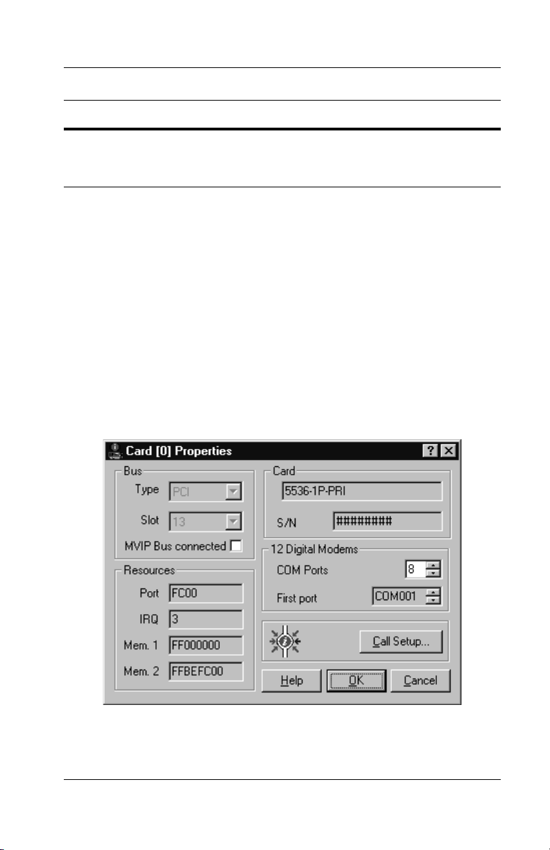
Chapter 5: Setting Up WAN Firmware and Hardware
Click... To do this...
Properties Configure a board’s hardware or port properties. You can
also use this button to access the Call Setup dialog box, as
described in Setting Up Calls on page 89.
Setting Up Card Properties
Use the Card Properties dialog box to view the board’s
hardware properties. Also, use this dialog box to enable or
disable the MVIP Bus connection (if applicable) or to change
the Serial COM ports assigned to the digital modems on the
board, if needed.
To display the Card Properties dialog box, in the Cards section
of the WAN Adapters Setup dialog box, select the 5536-DM
RAS card and click the Properties button.
The Card Properties dialog box appears:
Figure 5-2. Card Properties Dialog Box
5536 PRI RAS Communications Controller Users Guide 77
Page 98

Hardware Management
Most of the card properties are determined by hardware
features and cannot be changed. Only the MVIP Bus
connected field and the Digital Modems fields can be changed.
The following topics provide detailed information about
changing the MVIP Bus connection or digital modem setup.
Enabling or Disabling the MVIP Bus Connection
If the board is connected to an MVIP Bus, enable the bus
connection by selecting the MVIP Bus connected field on the
Card Properties dialog box. This allows the software to
recognize the card’s MVIP Bus connection.
To disable the Bus connection, deselect the field.
Assigning Serial Driver COM Ports to Digital Modems
After the Serial driver has been installed along with the Base
driver, you can change the Serial COM ports assigned to the
board’s digital modems. Eight COM ports are automatically
assigned to the digital modems during the software
installation. The Serial driver can emulate up to the same
number of COM ports as there are digital modems on the
board. It emulates COM ports over ISDN B channels.
To assign Serial driver COM ports to digital modems, do the
following:
1. To specify the number of COM ports to assign, on the
Card Properties dialog box, select the number in the
COM Ports field.
This should be the total number of COM ports for all
digital modems. The value must be between 0 and the
number of modems on the board.
78 Interphase Corporation
Page 99

Chapter 5: Setting Up WAN Firmware and Hardware
2. In the First Port field, if you do not want to use the
displayed port number as the first digital modem COM
port, select the port number to be used instead.
The COM port name indicates the number of the 5536
WAN board in the machine (starting at 0) and the port
number on the board (starting at 01). The first digit is for
the board number; the second and third digits are for the
port number.
For example, COM001 indicates the first 5536 WAN
board (0) in the machine, and the first port (01) on the
board. COM324 indicates the fourth 5536 WAN board
(3), and the twenty-fourth port (24).
The Serial driver will emulate the number of COM ports
specified in Step 1, starting with the selected first port,
and assign them to the board’s modems.
NOTE
To specify that no COM ports be emulated, select 0 in the
Digital Modems field. This selection removes the Serial
driver.
If you need to change default calling properties for the digital
modem ports, you can click the Call Setup button to access the
Call Setup dialog box. See Setting Up Call Properties on page
101 for information.
Also, depending on the applications you use with modems,
you might need to use Windows NT to identify (declare) Serial
driver digital modems to the operating system so the modems
can be detected when needed. For detailed information about
declaring and verifying the digital modems in Windows NT,
see Managing Serial Driver COM Ports on page 109.
5536 PRI RAS Communications Controller Users Guide 79
Page 100

Hardware Management
Setting Up ISDN Port Properties
If the 553x ISDN RAS Support driver is installed on the
machine, you can use the WAN Adapters Setup Utility to set
up the board’s port properties.
NOTE
Before you configure your ISDN PRI line, first obtain the
switch type and other necessary information about your
subscription from your ISDN provider.
To display the ISDN PRI Port Properties dialog box:
1. In the Cards section of the WAN Adapters Setup dialog
box, select the ISDN port you want to configure and
click the Properties button.
The ISDN PRI Port Properties dialog box appears:
Figure 5-3. ISDN PRI Port Properties
80 Interphase Corporation
 Loading...