

Page 1
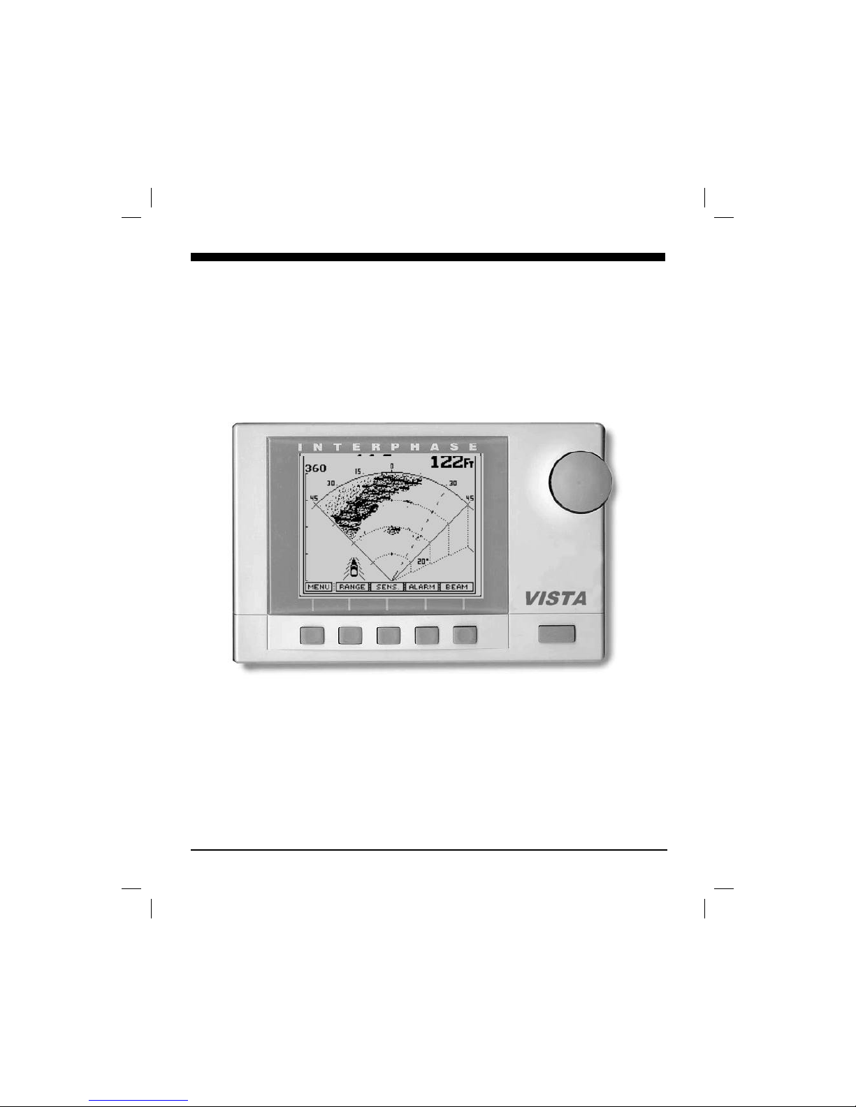
1
OPERATION
MANUAL
INTERPHASEINTERPHASE
VISTA
™
vistman1
page 1
Tuesday, July 06, 1999 10:15
Page 2

2
To Our Customer:
Thank you for choosing the Interphase VISTA Forward Scanning Sonar. Throughout the
development of this fine product, we have been primarily concerned with creating a unit that
offers the best possible value for your money. Selection of features, ease of use, superior
performance and outstanding reliability were the benchmarks upon which all important
design decisions were made. We feel proud of the VISTA Forward Scanning Sonar and your
satisfaction is very important to us. To this end, we welcome any comments or suggestions
that you might have in regard to this equipment.
It is very important that you complete and return the WARRANTY REGISTRATION
CARD within 15 days of purchase so that your unit may be protected under the warranty.
Sincerely,
INTERPHASE TECHNOLOGIES, INC.
©1998 Interphase Technologies, Inc.
Interphase Vista™ is a trademark of Interphase Technologies, Inc.
Publication # = Vista 1.0
vistman1
page 2
Tuesday, July 06, 1999 10:15
Page 3

3
Table Of Contents
Important Notice 4
Principle of Operation 5
Display Unit Installation 7
Transducer Installation 9
Basic Operation 16
Getting Started 17
Set-Up View 18
Demo Program 18
Units of Measure 18
Language Selection 19
Align Adjustment 19
FWD View (Full Screen Forward Scan) 20
Range Adjustment 20
Sensitivity Adjustment 20
Alarm Adjustment 20
Scanning Speed (Resolution) Adjustment 21
Down View 22
Range Adjustment 22
Sensitivity Adjustment 22
Bottom Hardness 23
Alarm Adjustment 23
Zoom & Bottom Track 23
Data View 25
Interpreting Your VISTA Display 26
Forward View 26
Noise and Sensitivity Adjustments 27
TVG 28
Frequently Asked Questions (FAQ’s) 29
Maintenance 30
Troubleshooting Guide 31
Interference Problems 32
Specifictions 33
How To Obtain Service 34
Warranty 35
vistman1
page 3
Tuesday, July 06, 1999 10:15
Page 4
4
General Information
Thank you for your selection of the Interphase VISTA
Forward Scanning Sonar. The VISTA’s ruggedly built,
compact design makes it ideal for installation on nearly any
boat. It will display water depth, bottom conditions and
submerged objects such as fish, or objects in your path, on its
high resolution display. The VISTA is available with either a
transom or thru-hull scanning sonar depth transducer.
The VISTA allows operation in your choice of nine
languages: English, French, Italian, Spanish, German, Danish,
Finnish, Swedish, or Greek. Power-off memory saves
language, depth range, gain and contrast settings, screen
advance speed and location in screen menu.
To ensure that you receive the maximum benefits available
from the outstanding features of the Interphase VISTA,
please carefully follow the steps outlined in this manual. An
instructive demonstration simulator has been designed into
the VISTA and we highly recommend that you spend some
time using the demo mode prior to actual use of the unit. We
also recommend that you read this entire manual before
attempting to either install or operate your VISTA.
Warranty Information
Interphase provides a limited warranty on the VISTA
Forward Scanning Sonar which is printed on the inside rear
cover of this manual. We recommended that you save all
packing materials so that if you should need to send in the
unit for repair, it can be fully protected. Should you
experience a problem with your VISTA, first refer to the
Troubleshooting section (Page 31) of this manual. Most
common problems and their solutions are described here. If
problems persist, call Interphase Product Support at (408)
477-4944. We will be happy to try to assist you, and if
required, we will give you instructions on how to quickly get
your set repaired.
The enclosed warranty registration card must be completed
and returned to Interphase within 15 days of purchase so that
your unit may be protected under the warranty. Failure to
return the warranty card may cause unnecessary delays in
processing your unit for warranty repair.
WARNING
Navigation based solely on one method or
one instrument should never be practiced.
While the VISTA can be quite useful in
showing underwater structure and changing
bottom conditions both below and in front of
your vessel, there are many situations and
conditions which can cause erroneous or
distorted readings.
In addition, there are many situations that can
cause “blind spots” in the VISTA’s field of
view including the presence of temperature
inversion layers (thermoclines), water
turbulence, and high concentrations of
suspended particles in the water.
While the VISTA can be considered as a
useful aid to navigation, it should never be
the only means of navigation.
IMPORTANT NOTICE
Since the VISTA’s Forward Looking
technology is revolutionary, there is a strong
possibility that we will develop many new
and exciting features in the future. We
would like to make sure we can send you
information about these new features and
enhancements.
Please fill out and return the Warranty
Registration Card immediately. This is our
only method to keep in contact with you and
we may want to advise you of future
enhancements to your VISTA.
If future changes or improvements are made,
software upgrades will be available for a
nominal charge.
vistman1
page 4
Tuesday, July 06, 1999 10:15
Page 5

5
Principle of Operation
The VISTA Forward Scanning Sonar uses a proprietary and
patented phased array acoustic technology first developed for
marine use by Interphase Technologies. Known as “phased
array ultrasound technology”, its capabilities have been
proven in the military and medical industries for many years.
The amazing video images provided by medical ultrasound
equipment are familiar to most people and clearly
demonstrate the technology’s ability to show highly defined
images in a "real time" or "live action" mode. Interphase has
taken this same technology and modified it for use in the
marine market.
Most present day fish finders/ depth sounders all work on a
principle developed during W.W. II, called SONAR, where
acoustic pulses are used to detect the presence and range or
distance to an underwater object. During the 1950’s, several
devices which used sonar principles were developed and
marketed to fishing and boating enthusiasts to detect the
distance to the bottom (depth) and to indicate the presence of
any intervening submerged objects - such as fish.
An acoustic array is a group of piezoelectric ceramic elements
that are precisely sized and spaced. Each element will send
and receive acoustic pulses, as when used in more
conventional single element depth sounders. However, when
all elements in the array are sending or receiving acoustic
energy at the same time, the entire array behaves like a single
larger element with one important difference: the ability of
the array to concentrate its acoustic energy in different
directions, depending on the different “phasing” of the signals
applied or received by each element. Depending on the signal
phasing of the array, acoustic beams can be directed in an
almost unlimited number of directions. For example, using
an 8 element phased array transducer, the VISTA is capable
of steering the acoustic beam in any of 60 different directions.
Conventional fixed-beam technology would require the use of
60 different elements to duplicate this capability. The
resulting transducer would be much too large and costly to be
of any practical use.
Since the acoustic beam in the phased array is steered
electronically, requiring no moving parts, it can be quickly
and reliably scanned and re-scanned over a large area. When
displayed, the changing information between subsequent
scans takes on an almost animated quality - for example,
Award Winning
Technology
For its pioneering work in
developing Phased Array
Scanning Sonar, Interphase
Technologies won the
prestigious IMTEC
INNOVATION AWARD.
The VISTA’s Forward
Looking Scanning Sonar is
based on this same awardwinning technology.
vistman1
page 5
Tuesday, July 06, 1999 10:15
Page 6

6
showing movement of underwater targets such as fish or
rapidly changing bottom conditions.
When operating, the VISTA converts a small amount of
electrical current from your battery into ultrasonic sound
pulses, which are then fed to the phased array transducer.
These acoustic pulses travel out from the transducer in a cone
shaped pattern, called the cone angle. When the sound pulse
strikes an underwater object, it is reflected back (echo return),
received by the transducer and converted back into small
electrical impulses. These impulses are amplified, then
displayed as an image on the LCD screen.
The strength of the echo, the depth of the object, and the
angle of the transducer’s beam all affect how the image
appears on the display. Other factors which affect the image
include boat speed relative to the movement and position of
the underwater target and the number of objects reflecting
pulses back to the VISTA.
Please Note:
The VISTA’s forward looking display is new and learning to
properly interpret scanning sonar takes both patience and
experience, but once mastered, the VISTA can offer
tremendous operational advantages over conventional fixedbeam depth sounders. It is also important to realize that
while the VISTA shows the bottom in both the forward and
the conventional downlooking mode, the presentations are
really quite different. The forward scan shows a view as the
beam “sweeps” across the bottom, while the conventional
downlooking view shows a history of repetitive soundings
packed tightly together.
vistman1
page 6
Tuesday, July 06, 1999 10:15
Page 7
7
Installation
Display Unit
The compact size of the VISTA display unit allows for easy
installation in almost any vessel. To get maximum
performance and life from your unit, the following guidelines
should be considered when selecting a mounting location:
1) Select a location where the unit is protected from
excessive temperatures. Heat is one of the worst enemies of
electronic components, and will accelerate component aging,
thereby reducing the trouble-free life of your VISTA.
2) Mount the display in a location where it will be
convenient to route the power cord and transducer cable.
Power connection
Connect the two-pin plug on the end of the power supply
cable to the power supply jack located at the rear of the main
display unit. Connect the red wire to the positive terminal
and the black wire to the negative terminal of your boat’s 12
VDC battery.
To minimize electrical interference, carefully route the power
cable so that it does not run parallel or close to the transducer
cable, engine, refrigeration, bilge pump or any other critical
wiring.
IMPORTANT: The VISTA’s 12 VDC power leads should
go directly to the boat’s battery, distribution board, or breaker
panel. Instability of the display may result if the unit has to
share leads with other electrical systems aboard your boat.
Wiring for Power and Transducer
Connectors
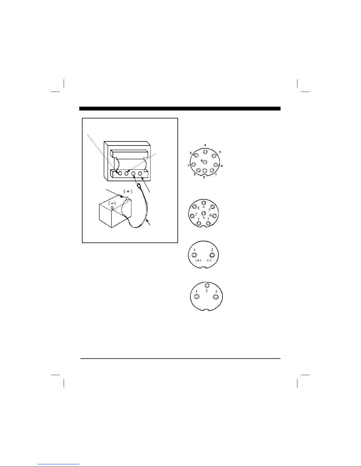
The correct pin-out wiring sequences for the power and
transducer connectors are shown at right. DO NOT
SHORTEN THE TRANSDUCER CABLE. If a transducer
cable longer than the 34’ length supplied with your unit is
needed, please contact your Interphase dealer. A 30-foot
scanning sonar transducer extension cable is available. (P/N
04-0014-008)
DANGER: Removal of any connector, disassembly of
transducer, shortening of any cable or use of any cable other
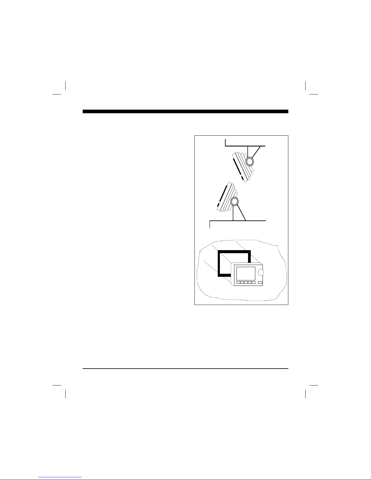
Shelf/Table
Overhead
Panel Flush Mount Installation
Optional flush mount bracket available
Interphase part # 17-0054-008
vistman1
page 7
Tuesday, July 06, 1999 10:15
Page 8
8
than that supplied by Interphase may void your
warranty.
Cable Connectors (view from front of female
plug)
9 Pin Transducer:
1 White 1st element
2 Brown 2nd element
3 Orange 3rd element
4 Yellow 4th element
5 Green 5th element
6 Blue 6th element
7 Violet 7th element
8 Gray 8th element
9 Shield Ground/Return
8 Pin Accessory
1 N/C
2 N/C
3 N/C
4 N/C
5 N/C
6 N/C
7 N/C
8 N/C
2 Pin Power Connector
1 +12 vdc
2 - (Ground)
3 Pin Accessory
1 N/C
2 N/C
3 N/C
N/C = No Connection
12 Volt Battery
Red Wire Accessory
(3-pin)
Transducer
(9-pin)
Accessory
(8-pin)
12 VDC
Power Cable
(2-pin)
vistman1
page 8
Tuesday, July 06, 1999 10:15
Page 9
9
Transducer Installation
The VISTA comes standard with either a transom mount
or thru-hull style forward scanning transducer.
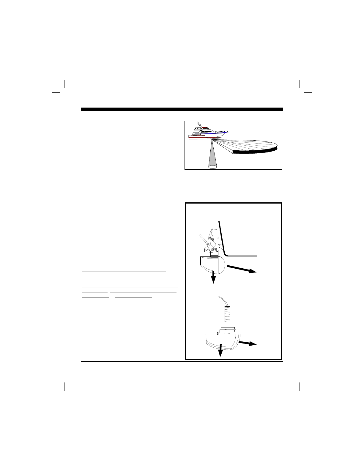
The VISTA’S transducer contains an 7 element ceramic
array in its front nose area and a single downlooking
element in the bottom area. The array is positioned so
that it can scan an ultrasonic beam from left to right
across the bow of the boat in a horizontal plane angled
downward at 15 degrees. The VISTA has an amazing
amount of capabilities, but it can not perform magic. It
can not see through objects such as your boat’s hull.
Therefore, it is important to position the transducer so
that it has as clear a view as possible of the water
directly ahead and to each front side of you boat, as
indicated in the top right illustration.
The scanning transducer must be positioned properly so
that it scans in the proper direction (i.e. from the port to
the starboard side). The sketch at right shows the proper
orientation for both the transom mount or the thru-hull
transducer. Note that on the transom mount transducer,
the rounded side must point forward, and on the thruhull transducer, the more blunt area must also point
forward. THE BLUNT SIDE OF THE TRANS-
DUCER MUST BE POINTED FORWARD!
General Considerations
DO NOT CUT OR SPLICE YOUR PHASED
ARRAY TRANSDUCER CABLE OR REMOVE
THE 9-PIN CONNECTOR BECAUSE THE
SYSTEM PERFORMANCE MAY BE SERIOUSLY
DEGRADED. THIS ACTION WILL VOID YOUR
WARRANTY. NO EXCEPTIONS.
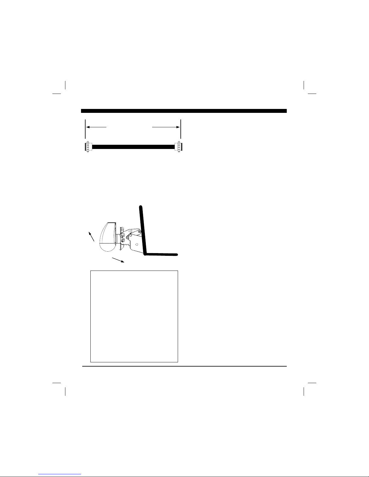
If you need a longer length cable than comes with the
transducer (33’), then purchase the optional 30’
extension cable, Interphase Part # 04-0014-008. It is
recommended that only one extension cable be used as
additional extensions will decrease the effective power
and depth range.
In addition to the above, the following considerations
should be observed:
Thru-Hull Transducer
Forward
Transom Mounted Transducer
Forward
Side View showing VISTA scanning
directions.
Down
Down
vistman1
page 9
Tuesday, July 06, 1999 10:15
Page 10
10
1) Choose a location where there is the least
amount of acoustic noise, air bubbles or turbulence
caused by the boat’s movement. The transducer should
not be located nearby or especially directly behind the
propeller.
2) Choose a location where the transducer can be
mounted so that it will be level to the water’s surface
and will not be tilted to either side. Otherwise the
transducer will not scan from the surface ahead to
directly beneath the boat.
3) The transducer must always remain
submerged, regardless of the speed of the boat and
should not be mounted where it could be damaged by
underwater obstacles or when loading on a trailer.
4) DO NOT locate the transducer in the extreme
bow of the boat where it will be subject to intense
turbulence as the boat pounds through the water.
5) DO NOT locate the transducer directly behind
any hull protrusion which will cause the water to be
turbulent when it reaches the transducer or which will
obstruct the transducer’s forward looking view. For
displacement-hull power and sail boats, the thru-hull
installation is usually required.
6) DO NOT force the cable by pulling on it. This
may cause damage to the internal transducer wiring.
DANGER: DO NOT allow any solvents, i.e. gasoline,
acetone, to come in contact with the transducer or head
unit as this may dissolve the plastic material.
Transom Transducer Installation
The transom transducer is attached to the boat with a
heavy-duty stainless kick-up bracket to provide
protection against impact at speeds up to 35 knots (40
MPH). When the water force exceeds this setting, the
transducer automatically kicks up and becomes nonoperational.
Transom Mounting Location
The main source of vessel acoustic noise is the propeller.
It is very important to position the transducer to
30’ Extension Cable
9-pin
Male
9-pin
Female
Interphase Part #
04-0014-008
Transom Mount Bracket in Released
Position
Suggested materials required for installation:
♦ Variable speed electric drill with a chuck
capacity of 10mm (3/8”) or larger.
♦ Hole saw or spade bit 19 mm (7/8”) for
transom hole to route cable and
connector
♦ Chamfer bit or 6 mm (1/4”) drill bit
♦ Drill bit No. 28 or 4 mm (9/64”)
♦ Drill bit 3 mm (7/64”)
♦ Marine bedding/sealing compound
♦ Note: Make sure your tooling is sharp and
of the correct diameter before proceeding.
Note: Will not
work at speeds
above 40 MPH
vistman1
page 10
Tuesday, July 06, 1999 10:15
Page 11
11
minimize noise pickup and provide as clear a view as
possible of the water ahead of the boat. Study the hull
shape of the vessel carefully to determine the best
transducer mounting location. To achieve optimal
operation the transducer should be mounted in a spot
which:
* Minimizes acoustic noise reception.
* Minimizes the chance that aerated water
will flow across the transducer’s frontal
nose area.
* Optimizes the transducers view of the area
ahead and directly below the boat.
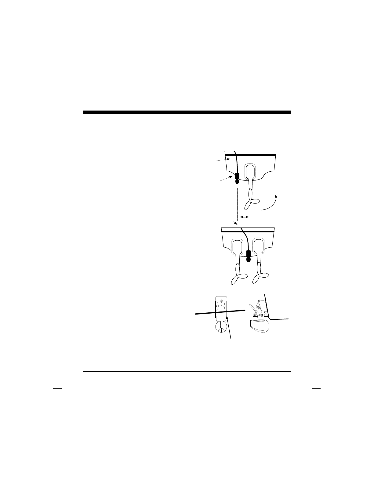
The transducer can be installed on either side of an
outboard or inboard/outboard engine, or between twin
outboards. For single engine installations, normally 18”
to 24” outboard of the propeller center line is acceptable
and the down stroke side of the propeller is preferred.
Choose a location where water flow is smoothest. For
dual engine installation, just off the center line is usually
acceptable.
Because the transducer rotates back and upwards when
the bracket releases, it must be mounted in a location
where there is sufficient clearance and headroom to
allow the full release.
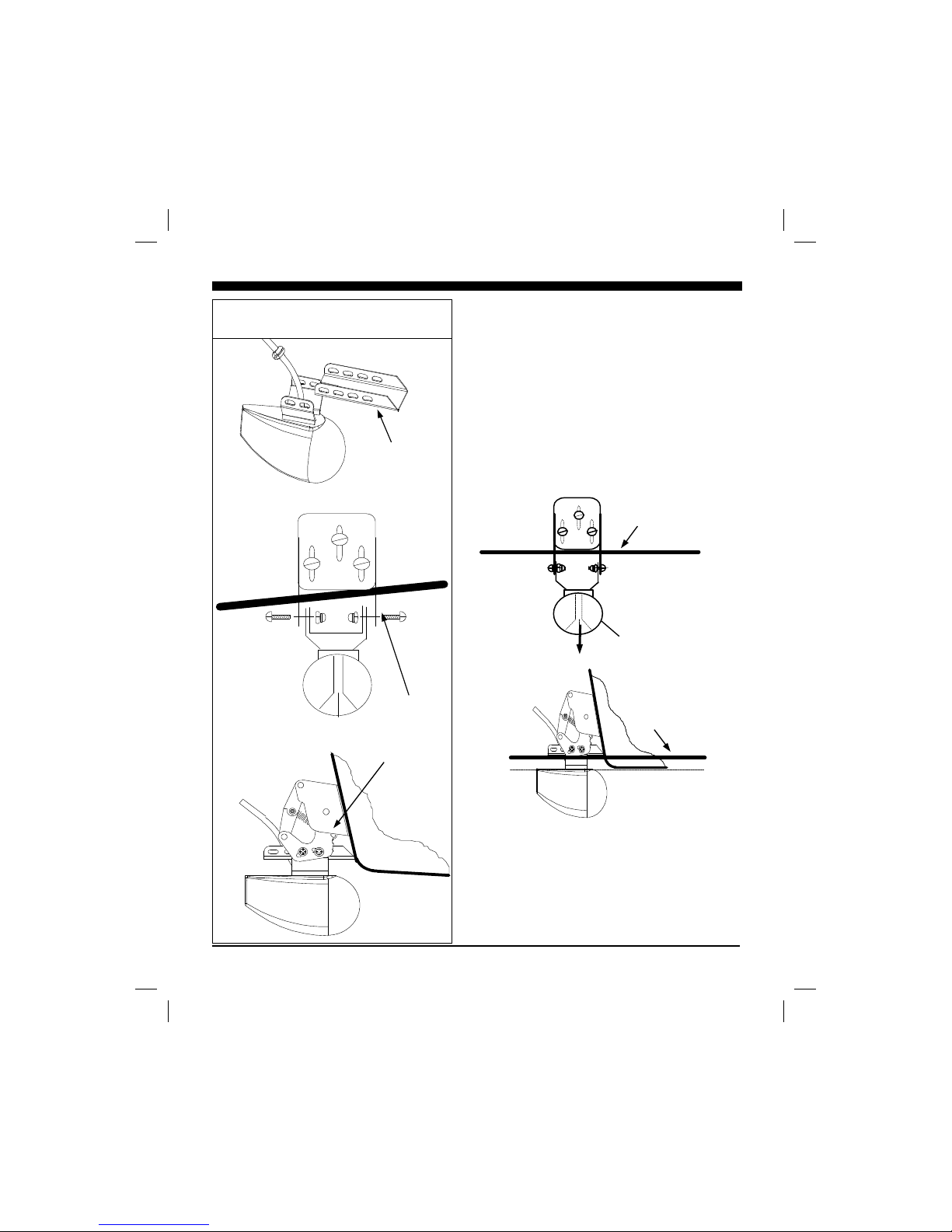
Attaching the Transducer and Spray Shield
to the Bracket
Locate the Stainless Spray Shield inside the transducer’s
stainless mounting ears. Make sure spray shield is
orientated as shown in sketch on following page.
Then, assemble the stainless kick-up bracket to the
transducers using the 4 screws, washers and lock nuts
provided. The bracket arms must be mounted outside
the stainless steel mounting ears of the transducer. Do
not fully tighten the lock nuts at this time.
Position the transducer so that it is perpendicular from
side to side and make sure the rounded shaped area is
pointed towards the front of the boat.
Mounting the Transducer to the Boat
After you have selected the optimum mounting location
and have assembled the mounting bracket to the
transducer, mount the bracket onto the hull as shown on
the right.
Make sure to position the transducer so that it is level in
the fore and aft direction and so it will look straight
Boat’s Hull
Transom Mount Locations
18 - 24"
Cables
Twin Outboards
Transducer
Cable
vistman1
page 11
Tuesday, July 06, 1999 10:15
Page 12
12
down. Check the location of your boat’s waterline and
position the flat top surface of the transducer so that it is
parallel to the waterline as shown below.
Note: If the transducer is not mounted so that its fore and aft
direction is parallel to the surface, then the forward looking
display will be distorted and flat bottoms will appear to be
slanted upwards or downwards. After mounting the
transducer and actually using the VISTA on the water, you
may need to readjust the transducer’s mounting for optimum
performance.
Thru-Hull Transducer Installation
The thru-hull transducer is the recommended choice for larger
boats with in-board engines. Thru-hull mounting is usually
required on larger power and sail craft in order to find a
mounting location free of forward looking hull obstructions.
The VISTA must have a clear view of the water ahead as it
can not magically see through obstructions such as the
Attach Transducer and Spray Shield to
Bracket
Fasten with
4 screws &
nylock
washers as
shown
Side
View
Rear View
Spray
Shield
Waterline
Transducer
must be
mounted
vertically
Rear
View
Side
view
Waterline
Mount Transducer So it Will Scan Properly
vistman1
page 12
Tuesday, July 06, 1999 10:15
Page 13
13
vessel’s hull. Please read the following carefully before
starting the thru-hull installation.
Normally, thru-hull installations are performed by a
professional in a boat haul-out facility. We suggest you seek
professional assistance before attempting to mount this
transducer.
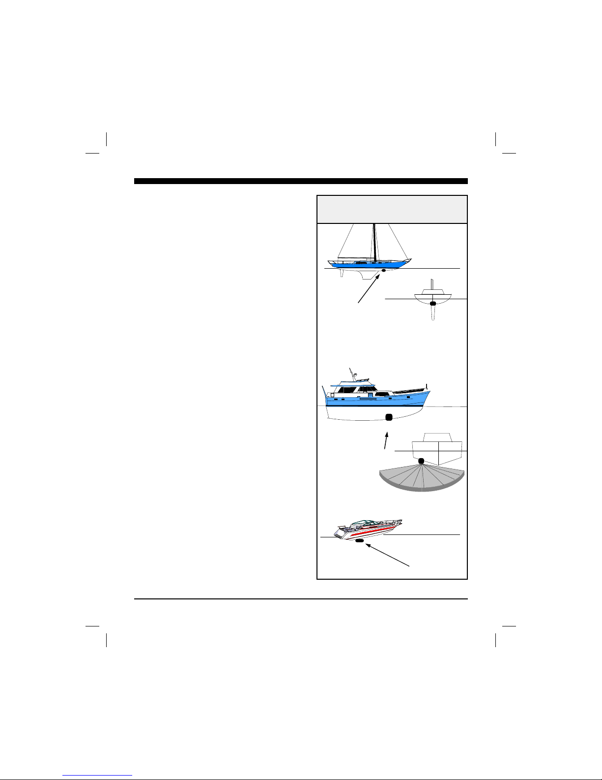
Selecting the Best Location
The best location to mount the thru-hull transducer will vary
with the type of boat. Try to find a location with the smallest
dead rise angle to make installation easiest.
a. On displacement hulls (sailboats, trawlers, etc.) locate
the transducer about 1/3 aft along the waterline. Generally
this provides the best compromise between obtaining
aeration-free water and minimizing propeller noise. The
VISTA’s transducer can not see through aerated water and
water near the bow and near the keel can be quite aerated.
Aeration of the transducer can be minimized by keeping the
transducer mounted away from the keel and by not mounting
too far forward. Because the Vista scans horizontally from
side to side, it is also important to find a location where the
beam will not be shaded by the keel. This can often be
accomplished by use of a fairing block to place the transducer
below the keel, or by mounting the transducer forward or
beside but at some distance from the keel.
b. On sailboats, the transducer should be mounted where the
acoustic beam will not be shaded by the keel. A spot forward
of a fin keel is usually best. Try to find an accessible spot
with a minimum dead rise angle.
c. On planing powerboat hulls, the transducer should be
mounted well aft and close to the keel to insure that the
transducer is in contact with the water at higher boat speeds.
On I/O’s, transducer mounting close to the
engine usually yields good results.
On inboards always mount the transducer
well ahead of the propeller(s). Turbulence
from props can seriously degrade performance. (Thru-hull installation is recommended.)
d. Mount the transducer on the side of the hull where the
propeller is moving downwards. The upward motion of the
propeller generates pressure waves and
pushes bubbles up against the hull.
DO NOT install a bronze transducer housing directly into an
Suggested Thru-Hull
Transducer Locations
Fin Keel
Planing Hull
Displacement Hull
vistman1
page 13
Tuesday, July 06, 1999 10:15
Page 14
14
aluminum or steel hull because electrolytic corrosion will
occur. Consult your boat-yard for information on
stainless or plastic sleeves.
IMPORTANT:
1) Make sure the water flow across the thru-hull
transducer is bubble and turbulence free at all speeds if
good performance is to be achieved.
2) Make sure the transducer has an unobstructed view of
the water ahead and below the boat.
3) On displacement-hull power boats, the transducer
should be mounted relatively close to the center line of
the hull.
4) Mount the transducer in a place which has reasonable
access from inside the vessel since the transducer’s
bronze nut will require tightening from inside the hull.
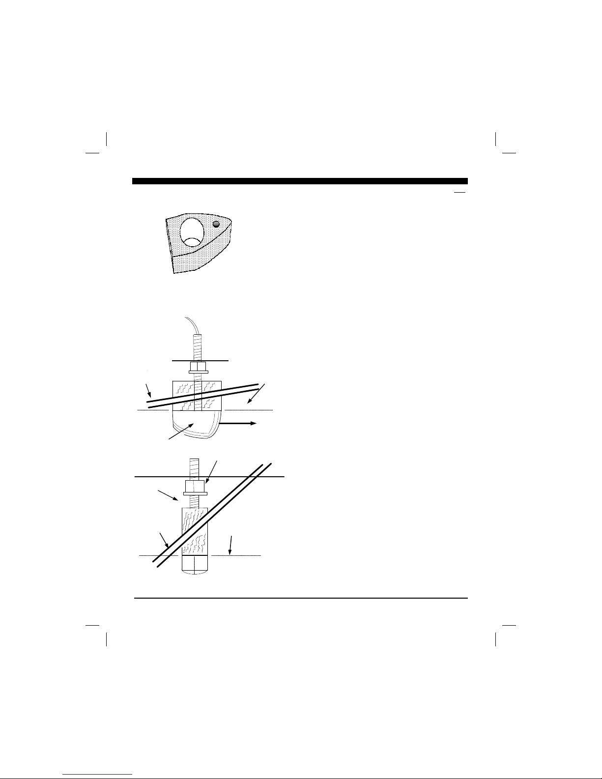
Because the VISTA scans a 12 degree beam from the
surface ahead to directly below the boat, it is important
to make sure that the transducer is installed so that it
will scan in a vertical direction and not off to either side.
The transducer must be mounted so that it’s bronze stem
is as perpendicular to the water line as possible. If
necessary, use a fairing block to properly position the
transducer.
Use of a Thru-hull Fairing Block
Nearly all vessels have some dead rise angle at the
transducer mounting location. If the thru-hull transducer
were mounted directly to the hull, the sound beam would
be tilted off the vertical at the same angle as the deadrise. Most thru-hull installations will require a fairing
block to insure the transducer is mounted properly.
A fairing block is typically made of teak or mahogany
wood or plastic and should be glued between the
transducer and hull (both inside and outside) to insure
that the transducer’s mounting shaft is perpendicular to
the water’s surface. Make the fairing block as smooth as
possible, and not bigger than the transducer’s face, to
minimize possible turbulence (see below).
After cutting the fairing block, trial fit the block to the
hull. It is very important that the flat top surface of the
transducer be parallel to the water. Because of the skill
required, we suggest that your professional boatyard
provide the fairing block.
Installing the Thru-hull Transducer
1) Drill a 1/8” pilot hole from inside the hull to assure
access to tighten the housing nut and clearance for the
Hull
Hull
Waterlin
Waterlin
Keep parallel
to waterline !
Keep parallel
to waterline !
Forward
Transducer
Mount Transducer so it is Vertical
Fairing Block Before Cutting
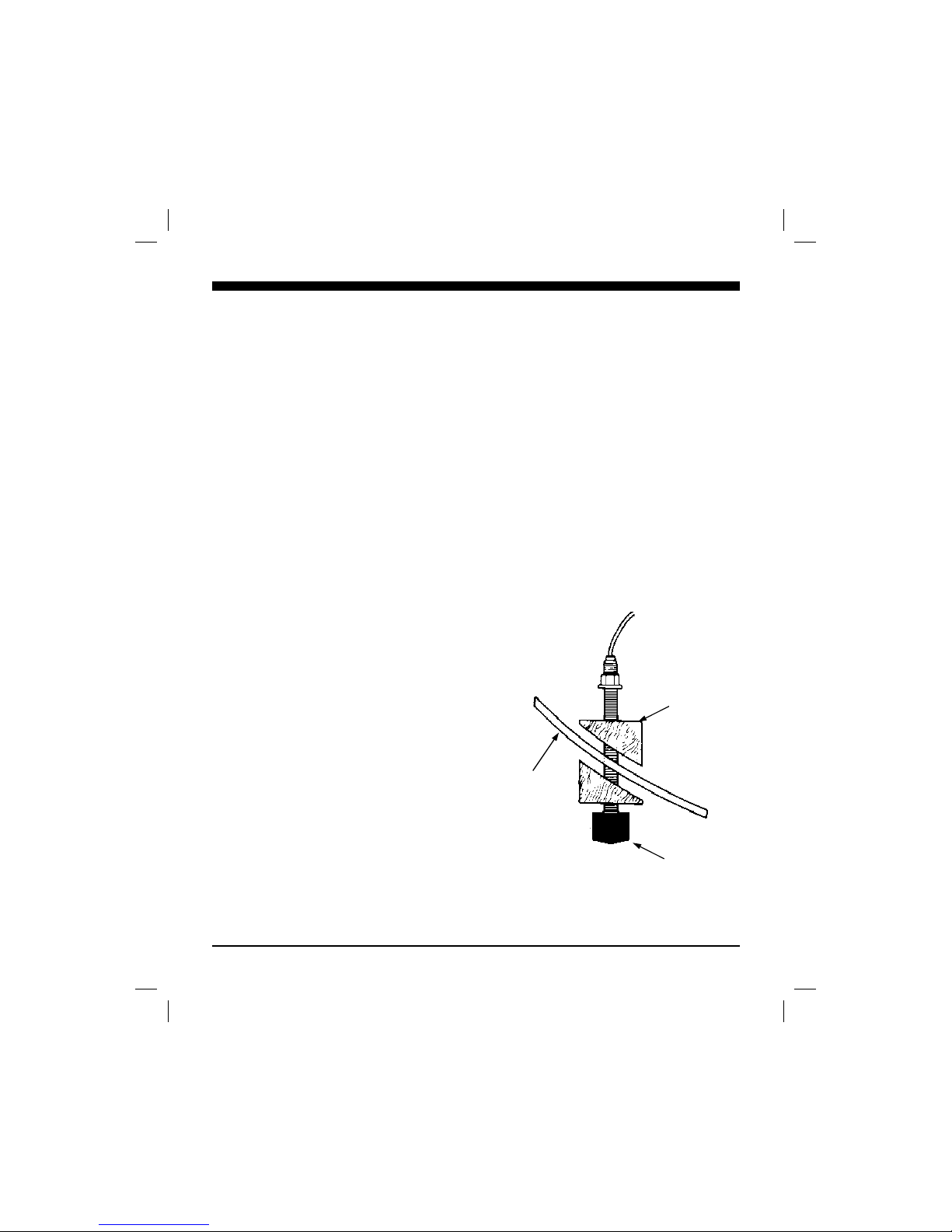
KEY matches hole
in
transducer’s
body (keeps
transducer
properly
positioned)
Safety
Washer
Split
Hex Nut
vistman1
page 14
Tuesday, July 06, 1999 10:15
Page 15
15
transducer cables. If there is any hull irregularity near
the selected mounting location, it may be desirable to
drill from the outside.
2) Use a 1” hole saw and drill the hole from the outside
of the hull. Sand or clean the area around the hole,
inside and outside to insure that the sealing compound
will adhere properly to the hull. Select a marine grade
bedding/caulking compound and use according to the
instructions.
3) Remove the split hex nut and the safety retaining
washer from the housing and cable.
4) Uncoil the transducer cable and thread it through the
hole into the inside of the hull.
DANGER: DO NOT apply tension to the transducer
cables as this may sever internal connections. Apply a
1/8” thick layer of sealant on the upper flat surface of the
bronze housing and fairing block (if used).
5) From the outside of the hull, push the housing into
the 1” hole. Twist the housing slightly to squeeze out
excess sealant. Carefully confirm that the transducer is
aligned so that the fatter end (the front) is pointed
directly toward the front of the boat.
6) Re-install the bronze safety washer (making sure
recess is towards nut so it will capture the hex nut).
Install and tighten bronze hex nut (allow for swelling in
wooden hulls).
7) Remove excess sealant from the outside to assure
smooth water flow over the transducer.
DANGER: Wood hulls and fairing blocks will expand
after the boat is put back into the water, so it is
important that the transducer be only hand-tightened
until the wood fully expands. Otherwise the wood
fairing block may crack.
DANGER: Be sure to check for leaks when the boat is
placed in the water. Allow at least 24 hours after
installation for any leak to appear.
DANGER: If the boat is kept in saltwater it is
recommended that the transducer be coated with an antifouling paint. USE ONLY WATER BASED ANTI-
FOULING PAINT. DO NOT USE KETONE BASED
PAINTS. Ketone based anti-fouling paint will attack
the plastic materials used in the transducer.
Transducer
Wood or
Plastic
Fairing
Block (Add
sealing
compound
between
faring block
& hull).
Boat’s
Hull
vistman1
page 15
Tuesday, July 06, 1999 10:15
Page 16
16
Basic Operation
The VISTA has been designed to be as easy to learn and
operate as possible. The raised push-button keys provide a
tactile feel to each operation and the VISTA responds with an
audible beep each time a key is pressed. All keys necessary
for operation of the unit are on the front panel. The VISTA
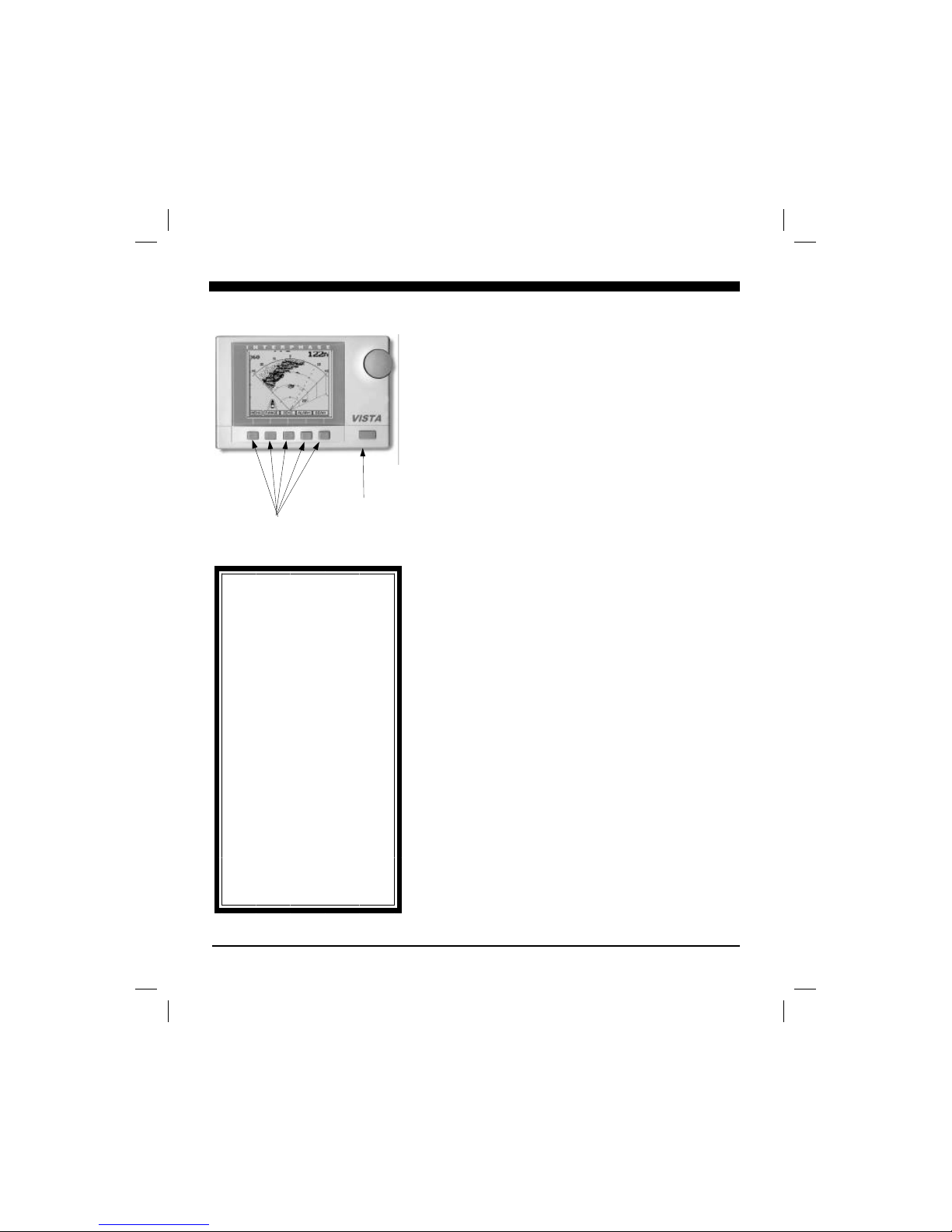
uses a unique approach called “soft keys” along the bottom of
the display. These five keys are labeled by the LCD display
and are controlled by the unit’s software, thus the name “soft
keys”.
In addition, a large front panel rotating knob eliminates the
need for multiple button pushes while making gain, depth
range, display contrast and many other adjustments. The
knob provides easy and quick adjustments while giving the
user a familiar style of operation.
Power/Backlight Key
Press the "Power/Backlight" key located at the lower right of
the unit to turn the VISTA on. The unit will respond with an
audible beep when it turns on. Pressing this key again turns
the backlight on and off, each time accompanied by a beep.
To turn the VISTA off, press this key and hold it down for
several seconds until the unit goes off.
Simulator/Demo Mode
Your VISTA includes a built-in DEMO simulator program
which makes it easy to practice with the unit and to get a
feeling for its many features before actually using it in real
situations on the water. We highly recommend you run
through this section on operation of the VISTA with the
DEMO mode activated to first learn basic feature controls.
The DEMO mode can be started from the SETUP menu as
described in the following section.
Cone Angle & Area Covered to Side
The VISTA’s Cone Angle is approximately 12 degrees. The
Chart at right shows the approximate width of the cone at
different distances from the boat. Although 50% of the
acoustic radiation is concentrated within this cone, 50% is
also outside the cone which permits the VISTA to detect
targets typically up to twice the cone angle, (i.e. 24 degrees).
This means, for example, that at 1,000 feet the VISTA will
typically be able to see targets across a 420 foot width (210
feet each side of center). See Figure at right.
Interphase Vista
Short-cut
In this manual you will find
instruction on how to change all
adjustable settings by using the “soft
keys”. However, any setting
adjustment can be done (when the
appropriate menu selection is made)
by turning the control knob.
Settings which can be adjusted by
using the control knob are:
Range
Alarm
Contrast
Sensitivity
Zoom
LCD screen contrast can be changed
any time while in the Main Menu
simply by turning the control knob.
Softkeys
Power On/Off
Backlight
vistman1
page 16
Tuesday, July 06, 1999 10:15
Page 17
17
Getting Started
Turning the VISTA On
To turn the VISTA on, press the Power/ Backlight Key
located on the lower right corner of the unit one time. The
unit should sound a beep and the display should be
illuminated. Press the left button until the Main
Menu appears as shown at below right.
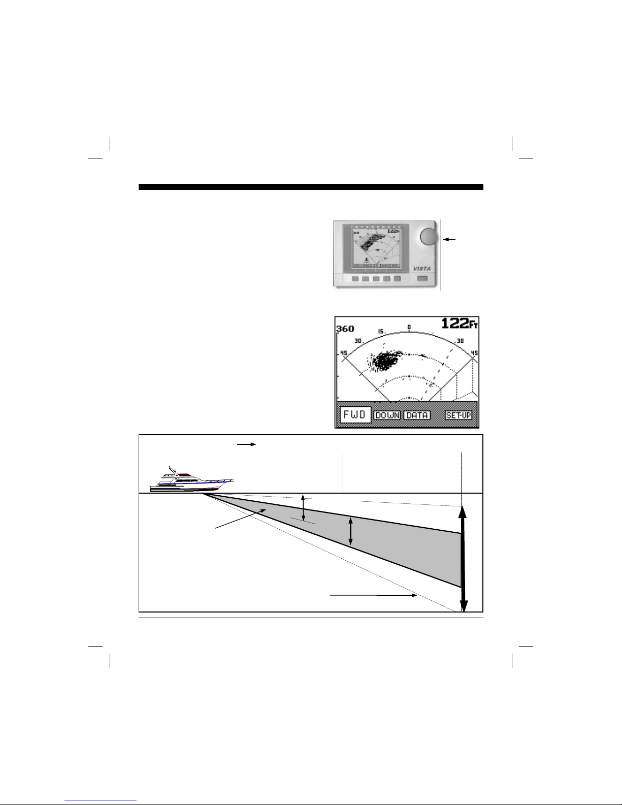
The Main Menu
From the Main Menu you can see that the VISTA has four
basic display modes or Views. They include:
♦ FWD (Full Screen Forward View)
♦ DOWN (Full Screen (Conventional Downlooking View)
♦ DATA (Split Screen View with Large Digit Depth on
left and Forward scanning display on right.)
♦ SETUP (Full Screen Set-Up View)
Each of these views can be easily selected by pressing the
button below the desired menu selection as shown above. To
return to the Main Menu just press the left button labeled
MENU. When first turned on, the VISTA’s internal
memory automatically sets the starting view to the last one
you used before turning off the power.
Interphase Vista
Control
Knob
VISTA’S MAIN MENU
250
500
210
52
FORWARD DISTANCE
1/2 Power Cone Angle
Vista can typically detect targets within
this area
20 degrees
vistman1
page 17
Tuesday, July 06, 1999 10:15
Page 18
18
Set-Up View
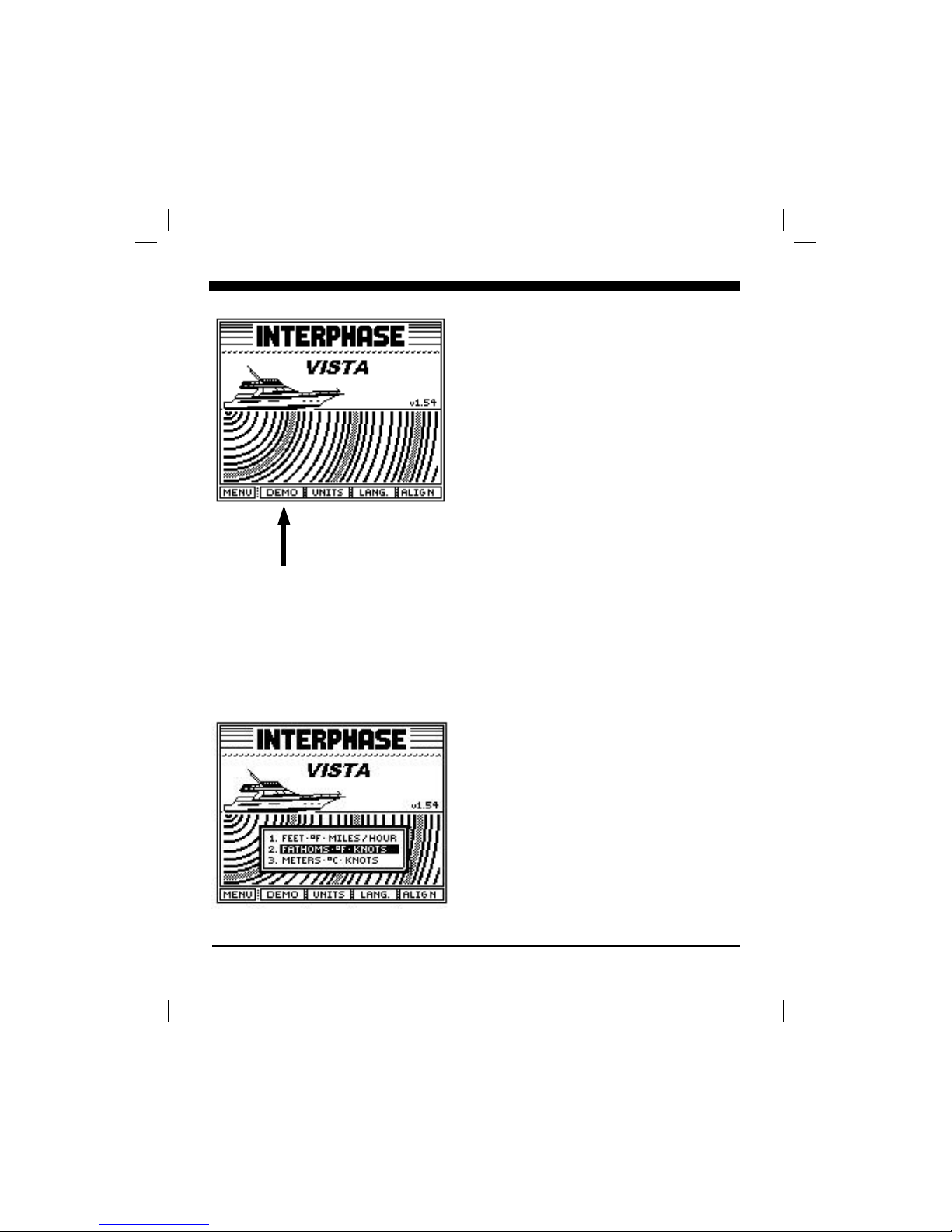
The VISTA includes a SET-UP View where the DEMO
program can be activated, the units of measure and language
can be selected and the display contrast can be adjusted. The
VISTA's internal backup battery will remember all settings for
future use.
From the Main menu press the button below the SET-UP to
put the display into the SET-UP View. The display should
appear as on the left.
Demo Program
We highly recommend you initially operate the VISTA in the
DEMO mode to familiarize yourself with the many advanced
features of the VISTA. When using the SET-UP view, press
and hold the soft key below DEMO until the unit beeps twice
and the word DEMO on the display changes to reverse video
as shown at left. This will activate the simulation program.
The unit will automatically cycle through a simulated
demonstration of its many features. At any time, you can press
any key to gain control of the DEMO program to make your
own selections and adjustments. If you do not press any button
for about 45 seconds, the unit will automatically resume
cycling through the different demo features on its own.
The pictures shown in the DEMO mode are representations of
what you might see on your VISTA. In actual use the picture
you will get can vary significantly depending on depth, bottom
and water conditions, the speed of your boat and many other
factors (see Interpreting The VISTA’s Forward Display, page
26).
To exit the DEMO program either turn the VISTA off and
back on again, or press the “DEMO” soft key again.
Select Units of Measure
The VISTA starts with the last units of measure selected. By
pressing the button indicated on the display, you can use the
large front panel knob to choose between U.S., Nautical and
Metric units. Rotate the front panel knob to select (highlight)
the type of display units desired. Once selected, press any
button to save your selection and exit. The current choice is
displayed each time the “UNITS” soft key is pressed.
vistman1
page 18
Tuesday, July 06, 1999 10:15
Page 19
19
The choices and their settings are as follows:
Feature U.S. Nautical Metric
Depth/Range Feet Fathoms Meters
(Ft.) (Fa) (M)
Select Menu Language
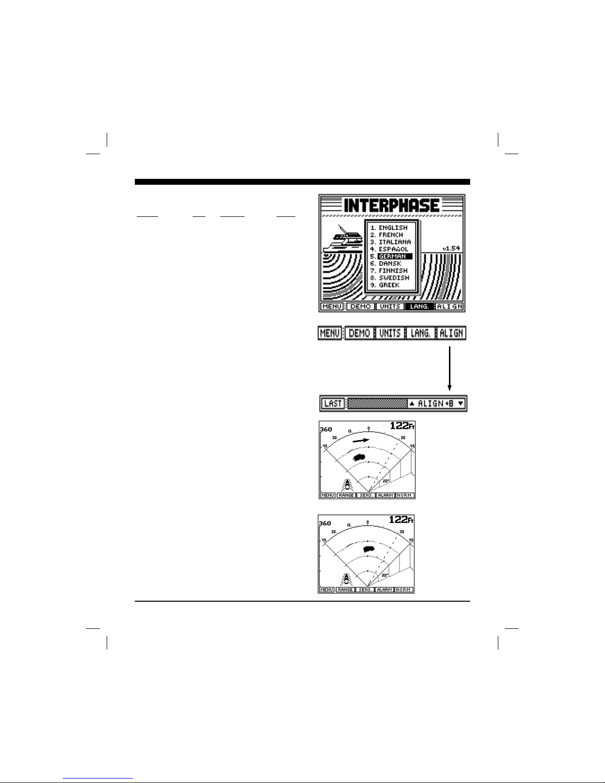
The VISTA allows the selection of 9 operating languages;
English, French, Italian, Spanish, German, Danish, Finnish,
Swedish and Greek may be chosen. To select the operating
language, press the button labeled LANGUAGE. A display
window as shown at right will pop up on the screen showing
the available languages and the one currently selected. Use
the large front panel knob to change (highlight) the language
selection. Once selected, press any key to save your selection
and exit.
Transducer Align Adjustment
The VISTA also includes an adjustment to compensate for
transducer installation problems, especially thru-hull
installations, where the transducer is not mounted so it points
straight ahead. This problem will cause targets directly in
front of the boat to appear shifted off to the port or starboard
side. Use the following procedure to identify and correct for
transducer misalignment.
When the boat is pointed directly toward a known target (such
as a piling or buoy, the target should appear in the center of
the VISTA’S FWD scanning display. If not, go to the
SET-UP and press the ALIGN button and turn the large
knob to adjust. The numbers in the ALIGN menu bar
indicate how many degrees to port or starboard that you’re
adjusting.
For example, if before the adjustment a known target directly
in front of the boat appeared approximately 5 degrees to the
left of center, then you would adjust the Alignment to +5.
Positive numbers move the target to the right (starboard) and
negative numbers move the target to the left (port). After
making the adjustment return to the FWD display to verify
that your setting has corrected the problem.
It is possible to adjust +/- 15 degrees. Once adjusted, the
VISTA’s memory will retain the setting.
Known target
directly ahead
of boat appears
left of center on
display.
In Align Menu,
rotate knob to
positive
numbers.
After making the
Align
adjustment, go
back to FWD
VIEW to check
that target is now
in center of
display.
vistman1
page 19
Tuesday, July 06, 1999 10:15
Page 20
20
Forward View (Full Screen)
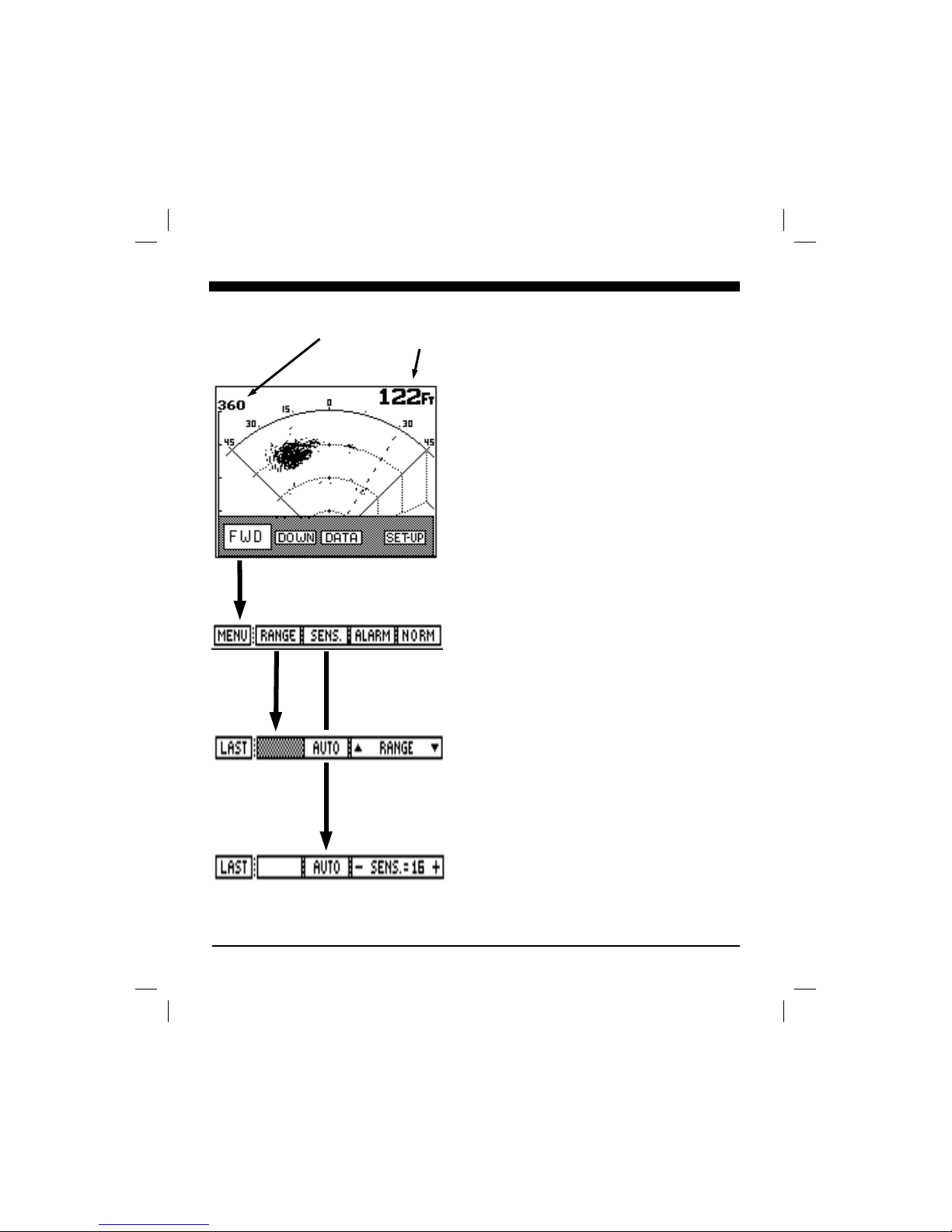
While in the Main menu press the button labeled "FWD" to
view a full screen forward looking display. At the top right
of the screen the current depth beneath the boat is shown in
digital numbers.
Your display menus should appear as on the left. Notice that
he current forward ranges is shown by the digital numbers at
the top left side of the LCD screen. The scanning screen has
four dotted range lines that are equal to 1/4, 1/2 and 3/4 of the
current forward range. The current range number on the left
top of the display will change as different ranges are selected,
either automatically or manually.
Range Adjustment
Press the button labeled "RANGE" to bring up the Range
Adjustment soft key menu as shown at left. Press the button
labeled "AUTO" if you would like the VISTA’s internal
microprocessor to automatically select and adjust the range as
bottom conditions change. To manually adjust the range
press either the range button labeled "Ç" or "È", or rotate the
large knob. If you make a manual depth adjustment, the
AUTO range mode is turned off and will remain off until the
button labeled AUTO is again selected. Note: when in the
AUTO mode, the soft key labeled AUTO will be shown in
reverse video (white on black). To return to the main forward
looking menu, press the left soft key labeled "LAST".
Note: The Auto Mode will only work if the Vista can find the
bottom. If the depth is greater than 320 feet or if the water is full of
bait or otherwise turbulent, the Vista will not work in the Auto
Mode.
Sensitivity Adjustment
Press the soft key labeled "SENS" (for sensitivity) to bring up
the choices available for adjusting the VISTA's receiver
sensitivity. Press the button labeled "AUTO" so that the
word AUTO is shown in reverse video (white letters on a
black background) if you would like the VISTA to
automatically adjust its sensitivity for changing conditions.
To manually adjust the sensitivity, either press the button
labeled “Sens.+” or “- Sens” or rotate the front panel knob.
Note that the soft key shows a number which indicates the
relative sensitivity being used (+1 to +32). When you choose
to manually adjust the sensitivity, the VISTA turns off the
AUTO sensitivity mode and it will remain off until the
AUTO soft key is again selected. To exit the sensitivity
menu and save your adjustments simply press the soft key
labeled “LAST” to return to the main forward looking menu.
Depth Below
The Boat
Forward Range
vistman1
page 20
Tuesday, July 06, 1999 10:15
Page 21
21
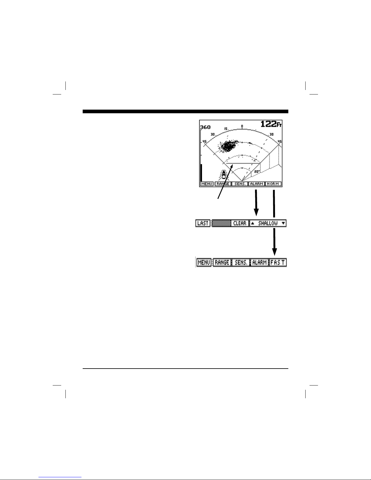
Alarm Adjustment
In the forward looking display or view, an alarm may be
adjusted to sound for targets which are closer to the boat than
the setting. This can be useful to warn of shallowing bottom
conditions or submerged objects.
To adjust or clear the alarm setting, press the soft key labeled
“ALARM” As either the up or down keys are pressed and
held down, or the large knob is rotated, a vertical bar on the
left side of the screen will move to show the area covered by
the depth alarm. In addition, a horizontal line will appear
across the display. Whenever a solidly displayed target
appears closer to the boat than the alarm bar, the audible
alarm will sound. (Note: the horizontal line will disappear
a few seconds after the alarm is adjusted)
The Close Alarm is often used to alert the user to shallowing
bottom conditions and the presence of underwater submerged
targets, and when activated, will sound a rapid beeping.
Press the "CLEAR" soft key to clear the alarm you
previously set.
Scanning Speed (Resolution)
In it’s normal scanning mode NORM, the VISTA will send
out 60 forward beams and will alternate between a forward
beam and the down-looking beam. In the FAST position,
only 30 beams will be used and the VISTA will send 5
forward scanning beams for every down-looking sample.
Use the FAST mode to get a faster picture update. The
resolution of the display decreases in this mode, but the
picture update is much faster than in the NORM mode.
Alarm Bar
vistman1
page 21
Tuesday, July 06, 1999 10:15
Page 22
22
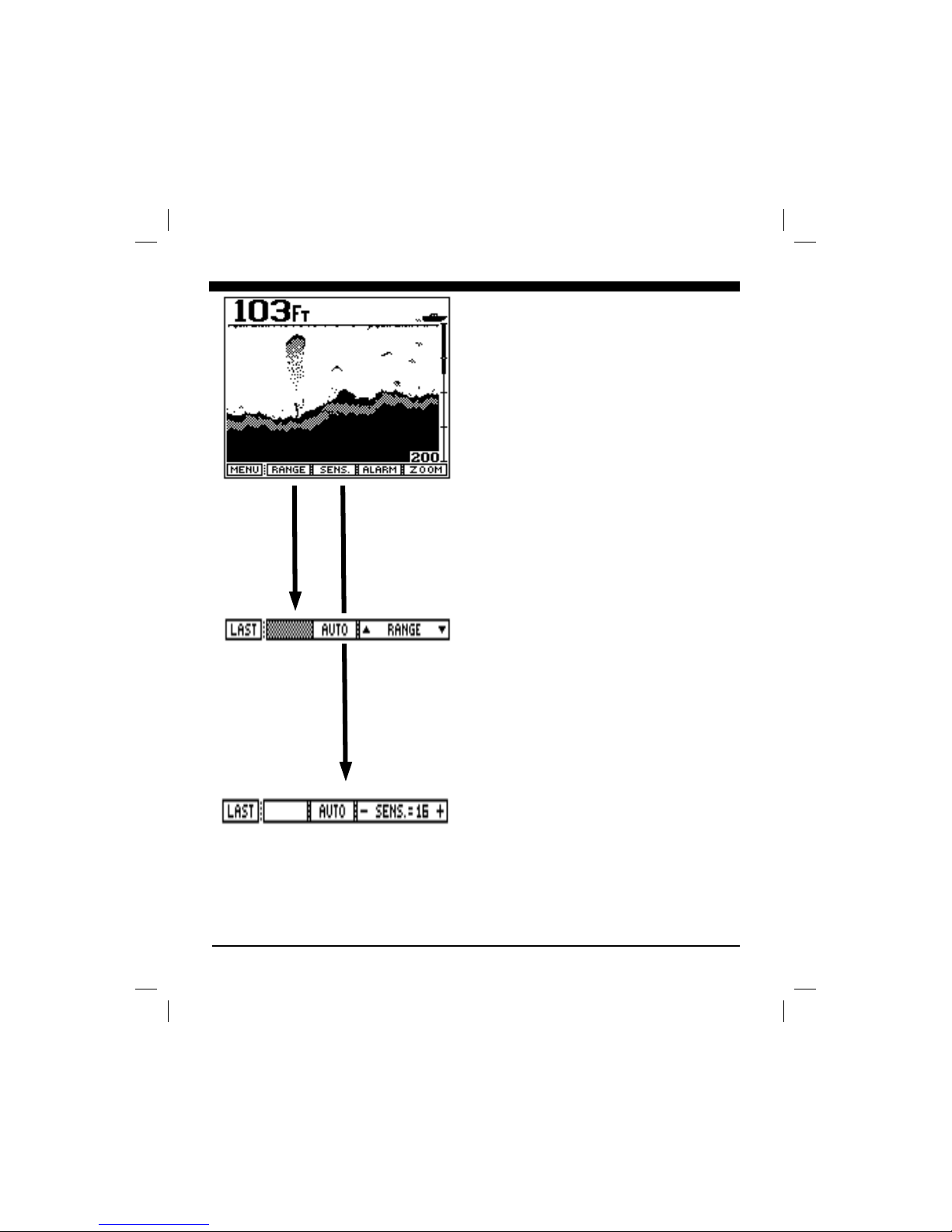
Down View
(Conventional down looking)
The VISTA’s phased array transducer includes an element to
look directly below the boat. In this mode the VISTA LCD
display will show a picture exactly like the conventional fixed
beam down-looking fish finders. When in this mode, the
VISTA offers a full range of sophisticated features which are
found on the more advanced conventional depth sounders
such as split screen zoom, bottom lock, a shallow depth
alarm, and bottom hardness (white-line).
From the Main menu select the DOWN button to bring up
the menu showing the features and adjustments for this view.
The display should be similar to that at left.
Range Adjustment
Press the button labeled RANGE to bring up the Range
Adjustment soft key menu. Press the button labeled AUTO
if you would like the VISTA’s internal microprocessor to
automatically select and adjust the depth range as bottom
conditions change. To manually adjust the depth, press either
the range button labeled "Ç" or "È". If you make a manual
depth adjustment, the AUTO range mode is turned off and
will remain off until the button labeled AUTO is again
selected. Note: when in the AUTO mode, the soft key
labeled "AUTO" will be shown in reverse video (white on
black). To return to the main forward looking menu, press the
soft key labeled "LAST". (To return to the Main menu press
the soft key labeled "MENU")
Sensitivity Adjustment
Press the soft key labeled "SENS." (for sensitivity) to bring
up the choices available for adjusting the VISTA's receiver
sensitivity. Press the button labeled "AUTO" so that the
word AUTO is shown in reverse video (white letters on a
black background) if you would like the VISTA to
automatically adjust its sensitivity for changing conditions.
To manually adjust the sensitivity, press the button
labeled“Sens.+” or “- Sens” to increase or decrease the
receiver gain. Note that the soft key shows a number which
indicates the relative sensitivity being used (+1 to +32).
When you choose to manually adjust the sensitivity, the
VISTA turns off the AUTO sensitivity mode and it will
remain off until the AUTO soft key is again selected. Note:
when AUTO mode is turned on the word will be displayed in
reverse video (white letters on a black background). To exit
the sensitivity menu and save your adjustments simply press
vistman1
page 22
Tuesday, July 06, 1999 10:15
Page 23
23
the soft key labeled “LAST” to return to the main
forward looking menu.
Hardness (White-Line)
The shaded area on this bottom display will give you an
indication of the bottom hardness. On a soft muddy or
sandy bottom the shaded area will be thinner and on a
hard rock bottom it will be thicker.
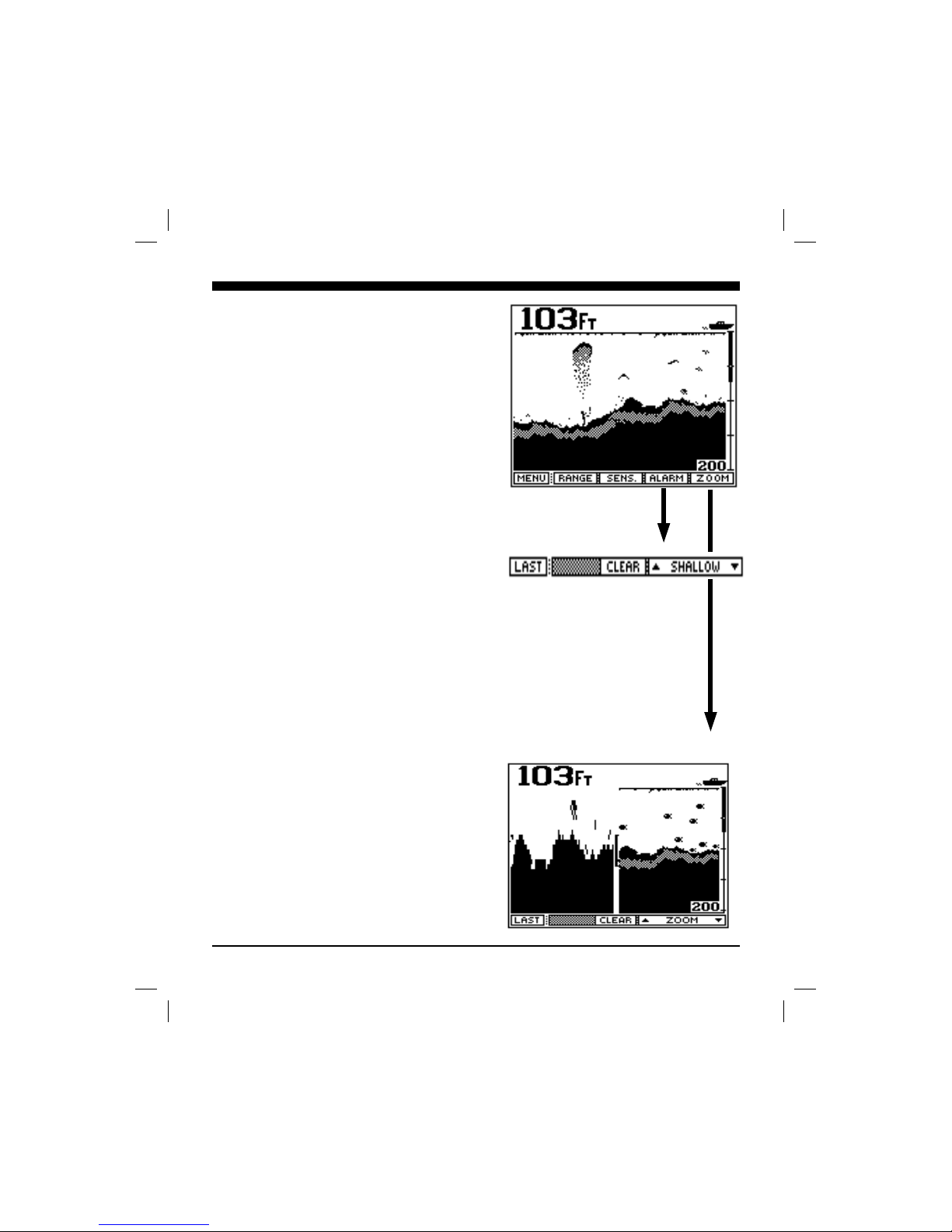
Alarm Adjustment
In the down looking display or view, a shallow alarm can
be set. To adjust or clear the alarm setting, press the soft
key labeled ALARM . As either the “Ç” or “È” keys
are pressed and held down, or the front panel knob is
rotated, a vertical bar on the right side of the screen
(just below the boat icon) shows the area covered by the
depth alarm. Whenever a solidly displayed target appears
at the same depth as that covered by the alarm bar, the
audible alarm sounds to warn you of underwater targets
or changing bottom conditions.
The Shallow Alarm is often used to alert the user to
shallowing bottom conditions and the presence of
underwater targets and can be even be used to detect the
presence of fish beneath the boat.
Zoom & Bottom Track & Bottom Lock
(Split Screen displays)
When using the Down display (conventional down
looking view), the VISTA can also display a split screen
high resolution zoom of any 25% of the depth range, or
can show a split screen Bottom Track or Bottom Lock
display. The high resolution Zoom is very useful when
looking for extra detail on the bottom or in areas above
the bottom. Because the VISTA uses an Interphase
unique 4X over-sampling technique, the zoom actually
shows more data than the non-zoomed picture.
Fishermen have long used the bottom locking features
when fishing over a rocky bottom or when fishing in
rough surface conditions. In the Bottom Track mode, a
zoomed view of the bottom is shown on the left side of
the split screen display. Regardless of changes in bottom
depth, the left side tracks it and keeps the zoomed bottom
picture in view. In the Bottom Lock mode, the bottom is
forced to appear as a straight horizontal line across the
bottom of the left side of the LCD while any targets close
to the bottom are displayed above the bottom line. Over
vistman1
page 23
Tuesday, July 06, 1999 10:15
Page 24

24
rough bottoms or in rough conditions, this feature is
extremely useful to eliminate rapidly changing bottom
depths from the display and to show only suspended
targets close to the bottom.
Press the soft key labeled "ZOOM ÇÇ" to activate the
split screen high resolution zoom function. The left side
of the LCD screen now shows the zoomed area, while the
right side continues to show the conventional depth
display. Hold down the "ZOOM ÈÈ" soft key (or rotate
the front panel knob) and notice the vertical bar moving
downward in the center of the display which shows the
depth area that is being “zoomed”. By using the "ZOOM
ÇÇ" and "ZOOM ÈÈ" soft keys, you can zoom in on
particular depth areas. The Zoom feature expands any
25% section of the current depth range on the left half of
the screen, or effectively magnifies the section selected
by the zoom bar by 400%.
If you move the zoom bar all the way to the bottom of the
display, the Bottom Track and the Bottom Lock
features can be activated.. When the Bottom Track
feature is activated, the Zoom Bar changes to a thin bar
extending from the top to the bottom of the display.
Pressing the “ZOOM ÈÈ” button once more activates the
Bottom Lock feature. When in Bottom Lock, the Zoom
Bar changes to a thick vertical line extending from the
top to the bottom of this display. Move the zoom bar up
to return to the regular zoom operation and turn Bottom
Lock off. Moving the zoom bar all the way to the top of
the display turns the Zoom off and returns you to full
screen bottom history.
vistman1
page 24
Tuesday, July 06, 1999 10:15
Page 25
25
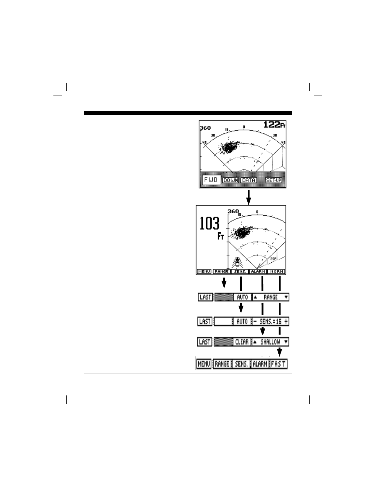
Data View
From the Main menu, press the soft key labeled DATA to
see a split screen display with large depth digits on the left
and a forward scanning view on the right. The large
digital digits show the digital depth directly beneath the
boat
Notice that the menu in the DATA view is exactly the
same as in the FWD view. You can adjust the RANGE,
SENSITIVITY, set an ALARM, or select the NORM or
FAST scanning modes in the same way that you can in the
full screen FWD mode.
Please refer back to the FWD section (page 20) for a full
description of how to make these adjustments.
vistman1
page 25
Tuesday, July 06, 1999 10:15
Page 26
26
Interpreting The Vista’s Forward
Display
The Interphase Vista provides a display which shows
acoustic echo returns from the underwater area below
and ahead of the vessel. The Phased Array Transducer
steers an acoustic beam over a forward arc of 90
degrees. As the Vista steers the beam to different
positions, it transmits a pulse of energy and then waits a
defined period of time (depending on the range selected)
to receive any return echoes. As the energy from this
acoustic beam strikes underwater objects or the bottom, a
small portion of the energy is reflected as an echo back
to the transducer. When the echo is received at the
transducer, it’s converted into a small electrical signal
and processed for display on the Vista’s LCD.
Since the Vista knows the direction in which it sent the
transmit pulse and the time it took to receive the return
echo, it can determine the location of the object or bottom
that created the return echo. As the Vista sequentially
steps the acoustic beam from the left to right and in front
of the vessel, the LCD display shows a continuously
updated display of the return echoes in their approximate
position in relation to the boat.
It’s important to remember that to show underwater
objects, the Vista must be able to actually “see” them. It
can not show forward areas that are hidden from its field
of view or are hidden due to obstructions in the acoustic
beam’s path through the water.
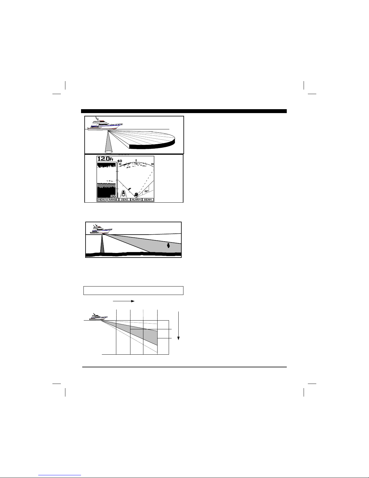
Forward View
The Vista scans from left to right across the boats bow.
The forward scanning elements in the transducer are
positioned so that the plane of the horizontal scan is
angled downward approximately 15 degrees from the
water’s surface (see sketch at right). This downward
angle is designed to help reduce the effects of surface
noise clutter when the water is choppy and to allow
easier mounting of the transducer to the transom of
smaller boats.
As the acoustic sound beam is projected away from the
boat, the cross-sectional diameter of the beam increases.
At a range of approximately 3 to 3.5 times the depth of
the water the sound beam will begin intersecting the
bottom and some of the sound energy that intersects the
Plane of Forward Scan is Angled 15 Degrees
Downward From Surface. Forward beam will
reach bottom at approx. 3.5 times depth
250 500
70
142
Forward Range
Depth
Beam Depth at Various Forward Ranges
Beam Depth =
Approx. .36 X
Forward Distance
vistman1
page 26
Tuesday, July 06, 1999 10:15
Page 27
27
bottom will be reflected back and will appear on the
Vista’s screen as bottom echos.
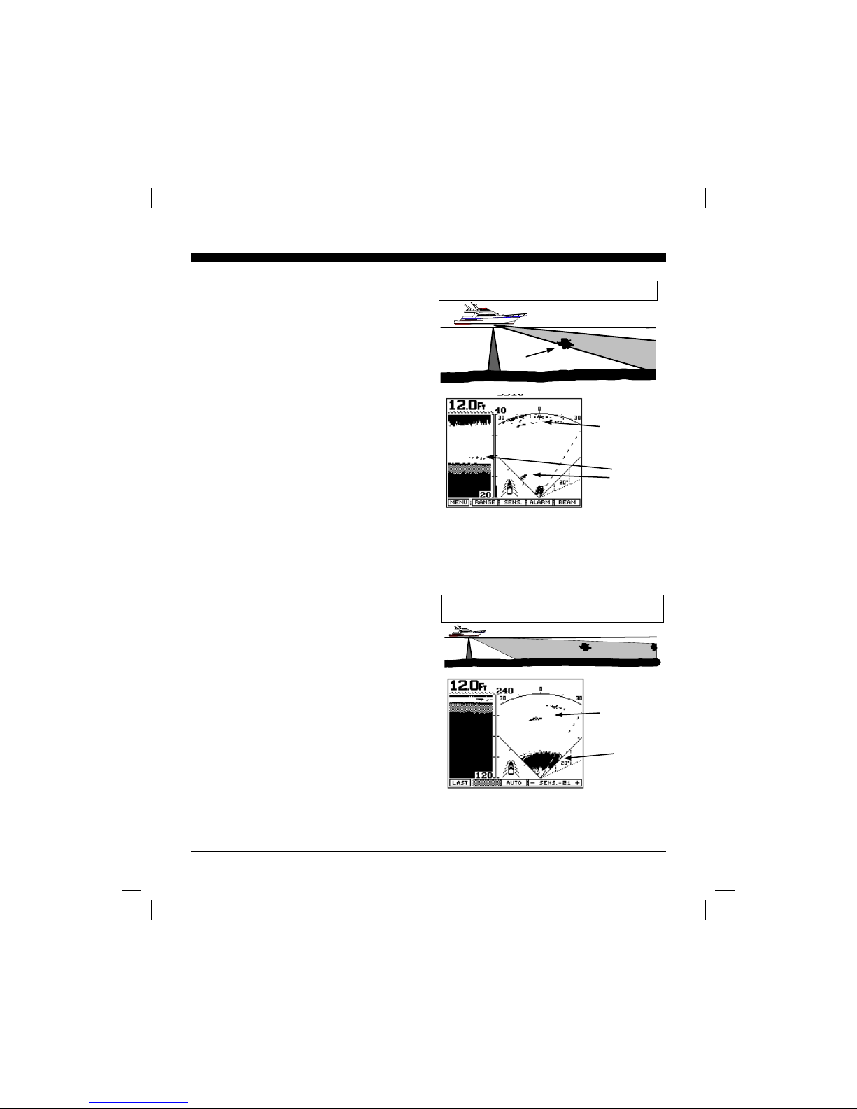
It is important to understand that the Vista will often
see the bottom and will show it on the forward display.
This display information can be used to help understand
the structure of the bottom ahead of the boat, but the
bottom echos can also mask or be confused as fish
targets. Several forward display situations with
comments are shown at right
The top picture and resulting screen display shows a
boat in 12 feet of water. The Vista’s forward range is
set to 40 ft. Notice on the scan picture on the right side
of the display, the bottom is just starting to show at
about 35 to 40 ft in front. A school of fish or bait is off
to the port side of the vessel at a forward distance of
about 14 feet and additional fish or bait appears directly
in front of the boat at a distance of only a few feet. Also
notice the fish or bait near the bottom on the
downlooking mode on the left side of the display.
In the lower picture and resulting screen display, notice
that even in shallow depths of 12 ft the Vista is
detecting targets at a forward distance of approximately
200 feet. When looking far forward in shallow
situations such as this, it is advisable to adjust the gain
manually. Otherwise the Auto gain feature will reduce
the gain because of the strong close-in bottom
reflections.
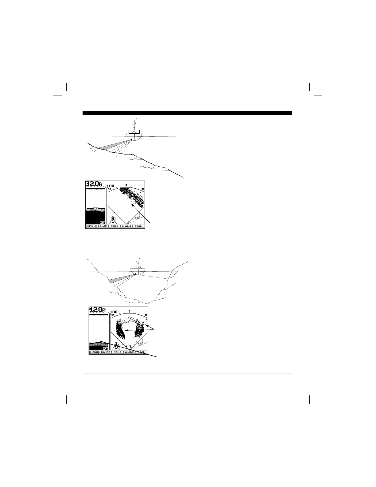
On the following page, two bottom situations are
sketched along with the resulting Vista Display.
Noise and Sensitivity Adjustments
The Vista features an AUTO sensitivity feature where
it continuously adjusts the sensitivity to achieve the
optimum picture quality. The sensitivity can also be
adjusted manually to allow for a reduction in sensitivity
to minimize the effect of screen noise, or to increase the
sensitivity to show weaker targets.
In the forward scanning modes, the sensitivity setting is
especially important as too little sensitivity will cause a
loss of target detection and too much sensitivity will
cause an increase in screen noise. In the AUTO mode,
the Vista increases the forward gain until there is a
certain density of targets on the display. In most
situations the AUTO gain mode works well, but
Bait
40ft Forward Range, Water Depth of 12 Ft
240ft Forward Range, Bottom Depth of 12 ft.
Fish or Bait
Bottom
Bottom
Bait
vistman1
page 27
Tuesday, July 06, 1999 10:15
Page 28
28
manual adjustments will often be required to get the
optimum picture - especially when looking far ahead in
shallow water.
TVG (Time Variable Gain)
As the acoustic signal travels through the water it is
attenuated in strength and also loses strength because the
signal is being spread over a larger and larger area. For
this reason, distant targets appear weaker than close
targets - even if both targets are of identical size.
The Vista’s receiver circuit includes a Time Variable
Gain (TVG) feature where the receiver’s gain is
controlled by the microprocessor and increases in value
as the depth or forward range increases. This feature
tends to compensate for the weakening of the signal at
longer distances as the receiver’s gain will be increased
as the signal gets smaller.
Sides of
Underwater
Trench
Bottom
Under Boat
Bottom Getting
Deeper to port
(left) of boat.
vistman1
page 28
Tuesday, July 06, 1999 10:15
Page 29

29
FREQUENTLY ASKED
QUESTIONS
How wide is the scanning beam?
The phased array scanning beam on all Interphase
scanning sonar operates with a 12 degree cone angle
is about 15' wide. The transducer operates at
approximately 200 kHz. The beam has many unique
as increased ranges.
How powerful (watts) are the Phased Array Sonar
Phased Array Sonar does not operate in the same way
that traditional marine sounders work. has
combined high-tech software with ultrasound technology
ultrasound technology. Interphase's
technology is now pending patent approvals. It operates
on approximately 420 watts (RMS tested at the
through eight (8) separate elements and the signal is
phased via our software.
look like?
The transducers for the are available in transom
or thru-hull configurations. If you are operating an
are measuring ahead from the transducer, therefore,
placing it as far forward as possible will provide you
The thru-hull transducers are slightly smaller than a
tennis ball and extremely hydrodynamic (they pass
The transom transducers are mounted on a stainless
steel kick-up bracket in order to minimize the possibility
bracket will 'kick-up' at speeds in excess of 20 knots.
Therefore, if you intend on using the forward scan
high speed, you will need to consider a thru-hull
transducer.
vistman1
page 29
Page 30

30
Maintenance
The Vista Forward Scanning Sonar has been designed to provide reliable, trouble-free performance for years. Follow the maintenance
tips below to ensure that your Vista remains problem free.
1) Keep your Vista clean and dry. Occasionally wipe unit off with a damp cloth, but be careful not to scratch the lens covering the
LCD screen. For stubborn dirt, use a mild soap and a damp cloth. NEVER USE SOLVENTS SUCH AS PAINT THINNER,
ACETONE, OR GASOLINE TO CLEAN YOUR Vista.
2) Occasionally clean the face of the depth transducer (sensing surface) and carefully remove any marine growth. Use a mild detergent,
or 220 grit sandpaper, or crocus cloth to remove stubborn growth.
3) If the in-line fuse is blown, replace it with a 2 amp fuse. NEVER REPLACE WITH A HIGHER AMP RATING ! If the fuse
continues to blow, check the polarity of your 12 VDC power source. If the polarity is correct, check with the Technical Service
Department at (408)477-4944.
4) In order to protect your transducer from water damage, paint it with one of the following brands: Interlux-UltraCoat, Fiberglass
Bottom Coat, Super Bottom Coat; Pettit-UniPoxy; Rule-Super KL, Gloss Dura Poxy. DO NOT use a solvent based paint.
5) DO NOT allow any solvents, i.e. gasoline, acetone, to come in contact with the transducer or head unit as these may
dissolve the material.
vistman1
page 30
Tuesday, July 06, 1999 10:15
Page 31

31
Troubleshooting Guide
If you are experiencing trouble with your Vista, please refer to the following checklist:
PROBLEM SOLUTION
Unit will not turn on. Check fuse, battery voltage and power connections.
Also, check for continuity through the in-line fuse holder.
Unit beeps but no picture appears Check your connections to the battery. Check for
on the screen. corrosion on the battery terminals or on the wiring
connections on a fuse block or buss bar.
Unit blows fuses. Wiring is reversed or there is excessive current from the
battery. The red wire should be “+” (positive) and have
continuity with pin #1 on the female side of the power
supply lead.
Loses picture at speed. Adjust the transducer angle or placement. Make sure that
the transducer is installed in the area which has the least
amount of water turbulence.
LCD darkens in sunlight after Overexposed to sunlight - provide shading for display.
prolonged use.
Screen is full of noise, or has dots Reduce your gain setting and review the section on
running through it. interference.
Bottom slopes up/down Adjust the transducer angle.
Digital water depth not working. Increase your gain, and check that you are in the proper
depth range.
vistman1
page 31
Tuesday, July 06, 1999 10:15
Page 32

32
Interference can come from several sources. The most common of these are:
Other nearby depth sounders operating at the same frequency.
Radiated interference from the boat’s electrical system (alternator, distributor and spark plugs) or from nearby
3) Vista
(i.e.; bilge pumps, motors, refrigeration systems, autopilots, etc.)
Vista
appear as “rabbit tracks” that march up and down the screen. Reducing the gain will help minimize this problem.
Vista
engine running and turned off. If the interference disappears when the engine is turned off, it is safe to assume that
This type of interference can usually be eliminated by using the same techniques used in the automotive industry to
1)
2)
3)
4)
Interference may also be caused by radiation from other nearby equipment and can be detected by turning off all
Vista
interference can usually be eliminated by moving the away from the source and checking to ensure that the
Interference causing the display to be unstable, to pulsate or periodically change size is usually caused when another
equipment requiring large current surges (i.e.; autopilots, refrigerators, or bilge pumps) share the same power leads.
Vista’s
equipment, directly to the battery.
electronic gear (e.g.; fishfinders, VHF radios, radar units, etc.). If your unit shuts off during low voltage situations,
system. An “A/B” system allows you to run your electronic gear on one battery, while the starter and alternator are
Your authorized marine electronics dealer is familiar with the methods of reducing electrical interference and is
vistman1
Page 33
33
Display Type: 128 x 160 pixels; 20,480 total pixel Super Twist LCD
Depth Ranges: 18 overlapping depth ranges, 0 - 20 to 0 - 320 feet
Forward Ranges: 18 overlapping forward ranges, 0 - 30 to 0 - 600 feet
Transmit Frequency: 200 kHz
Zoom Ranges: Variable Zoom allows 25% of depth range to be displayed
across the entire screen.
Pulselength and
Sounding Rates: Automatically optimized for selected range.
Transmitter Power: Over 400 watts RMS (3,200 watts peak to peak)
Power Requirements: 10.5 to 16 VDC, less than 0.5 Amp.
Dimensions: 7.5”W x 5.5”H x 3.5”D
Standard Equipment: Display unit, 12 VDC power cable with in-line fuse, mounting
bracket with knobs, operation manual and depth transducer w/ 30’
cable.
Specifications
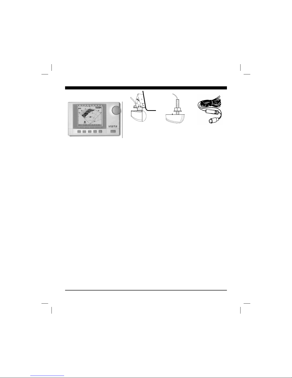
12 VDC Power
Supply Cable
Part # 04-0001-008
Depth only
Thru-Hull Transducer
Part # T1-0200-029
Depth only
Transom Transducer
Part # T1-0200-028
vistman1
page 33
Tuesday, July 06, 1999 10:15
Page 34

34
How to Obtain Service
If you feel your set is not operating properly, first refer to the sections of this manual on Troubleshooting and
Interference Problems. This information solves the most common problems. If problems persist, please call
Interphase Technical Service at (408)477-4944 or send your unit in with the information below filled out.
If you do need to return your set, send it to the following address:
Service Department
Interphase Technologies, Inc.
2880 Research Park Drive, Suite 140
Soquel, CA 95073
In addition, to speed your repair please fill out the following, tear this page out of the manual (or photocopy it), and
tape it to your unit for our technicians to review. For fastest warranty service, include a copy of your purchase
receipt to verify the purchase date.
RETURN TO:
(Your Name)
(Street Address - No P.O. Boxes Please)
(City) (State) (Zip)
Daytime Telephone: ( )
Evening Telephone: ( )
Model: Vista Serial #:
Purchase Date / /
Type of transducer: Transom mount Thru-Hull Other
Please describe the problems you are having with the unit in as much detail as possible in the space below. Please
use another sheet of paper if necessary.
vistman1
page 34
Tuesday, July 06, 1999 10:15
Page 35

35
Interphase Technologies, Inc.
Limited Warranty
Interphase Technologies, Inc. warrants this product to be free from defects in
material and workmanship for one year from the date of purchase.
Any unit that fails during the warranty period will, at Interphase’s option, be
repaired or replaced at no charge to the customer provided it is returned to
Interphase, freight prepaid with proof of date of purchase and a description of
the malfunction. Repair or replacement during the warranty period will not
extend the basic warranty period.
This warranty does not apply to an Interphase product that has failed due to
improper installation, misuse, or accident, nor does it apply to products which
have been repaired or altered outside the Interphase factory.
Any costs incurred with transducer replacement are specifically excluded from
this warranty other than the cost of the transducer itself.
This warranty does not include incidental or consequential damages and
Interphase disclaims any liability for any such damages. All implied
warranties, if any, are limited in duration to the above stated one year warranty
period. Some states and provinces do not allow the exclusion or limitation of
incidental or consequential damages, therefore, the above limitations may not
apply to you.
The completion and return of the enclosed Warranty Registration Card is
a condition precedent to the warranty coverage.
This warranty gives you specific legal rights which may vary from state to state
and province to province. This warranty is limited only to the original
purchaser of the unit.
vistman1
page 35
Tuesday, July 06, 1999 10:15
 Loading...