

Page 1
Interphase is a trademark of Interphase
Technologies, Inc.
Copyright 2007 Interphase Technologies, Inc.
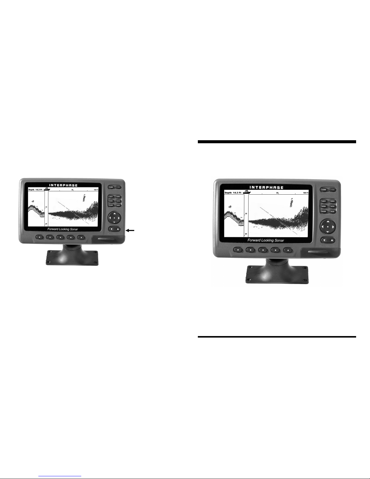
NOTE:
THIS BUTTON
CONTROLS
SCREEN BRIGHT-
NESS ONLY
INTERPHASE
7” VGA Display
INSTALLATION
INSTRUCTIONS
Page 2
Installation
Display Unit
To get maximum performance and life from your unit, the
following guidelines should be considered when selecting a
mounting location:
1) Select a location where the unit is protected from excessive
temperatures. Heat is one of the worst enemies of electronic
components, and will accelerate component aging, thereby
reducing the trouble-free life of your 7” Display.
2) Mount the display in a location where it will be convenient
to route the power cord and VGAcable.
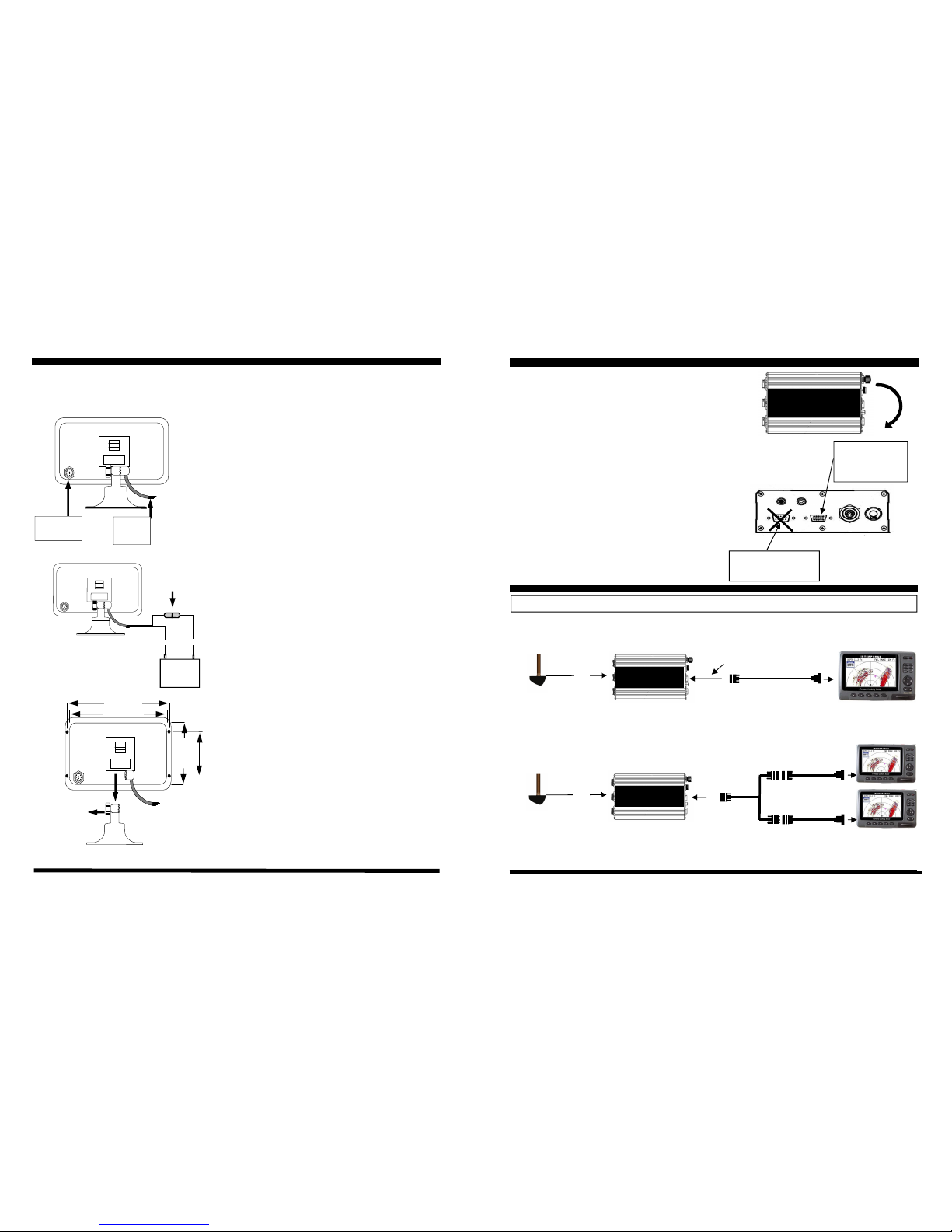
Power connection
The Display’s power leads are the red and black wires inside
the cable that connects to the rear mount. These wires must be
connected to a source of 12VDC voltage. The red wire should
connect to the plus (+) 12 VDC and the black wire should be
connected to the minus (-) side of the 12 VDC.
To minimize electrical interference, carefully route the power
cable so that it does not run parallel or close to the transducer
cable, engine, refrigeration, bilge pump or any other critical
wiring. An in-line fuse holder is included with your unit and
should be placed in the positive lead as shown at left. A 2
Amp fuse is included.
In - Dash Mounting
The 7” Display comes with mounting hardware panel
mounting. Four mounting screws and a cutout diagram are
included.
For panel mounting, the mounting base portion of the Quick
Disconnect Mount is removed. To remove the mounting base
loosen the thumb screw until it seperates from the upper
portion of the Quick Disconnect Mount.
While the cutout template is included, dimensions of the cutout
and pilot holes have also been included in the drawing at left.
Rear Panel Connections
VGA/
Keypad Input
Power
and I/O
(-)
(+)
2 Amp
Blac
Re
Loosen to
remove
8.3” [211mm]
8.7” [220mm]
3.9” [100mm
5” [126mm
Connecting 7” Display to SE-200 Engine
The 7” Display includes a special 10’ long 9-pin to VGA
cable. The 15 pin Female end of the cable connects to the
15-pin male connector on the Sonar Engine (labeled
DISP). If male-male VGA extension cables are used, a
gender changer will be required to interface with the male
connector on the sonar engine box.
WARNING: DO NOT CONNECT OR
DISCONNECT THE VGA CABLE
FROM THE SONAR BOX WHILE
THE UNIT IS TURNED ON. THE
MALE VGA PINS WHICH CARRY
VOLTAGE CAN EASILY BE
SHORTED TO GROUND
CONNECTIONS WITH INTERPHASE VGA DISPLAY
30’
TRANSDUCER
INTERPHASE
SE-200
VGA Female to 9-Pin Male Cable.
Can Extend with standard Female to Male
VGA Cable or standard Male to Male VGA
Cable with Gender Changer.
SPECIAL INTERPHASE DISPLAY
WITH INTERGRAL KEYPAD VGA
CABLE SPLITTER.
P/N #04-1095-000R
(Female to two Males)
30’
TRANSDUCER
INTERPHASE
SE-200
TWO- STATIONS
SINGLE STATION
INTERPHASE
SE-200
DO NOT USE FOR INTERPHASE
7” DISPLAY—ONLY FOR FLAT
PANEL DISPLAYS
DISP
OUTPUT
(15 PIN MALE)
CONNECT 7” DISPLAY
TO THIS CONNECTOR
 Loading...