


To Our Customer:
Thank you for choosing the Interphase Ultrascan PC90 Forward Scanning Sonar.
Throughout the development of this fine product, we have been primarily concerned with
creating a unit that offers the best possible value for your money. Selection of features,
ease of use, superior performance and outstanding reliability were the benchmarks upon
which all important design decisions were made. We are proud of the Ultrascan PC90
Forward Scanning Sonar and your satisfaction is very important to us. We welcome any
comments or suggestions that you might have about this equipment.
It is very important that you complete and return the WARRANTY REGISTRATION
CARD within 15 days of purchase so that your unit may be protected under the warranty.
Thank You Again,
INTERPHASE TECHNOLOGIES, INC.
Interphase Ultrascan PC90™ is a trademark of Interphase Technologies, Inc.
Other brands or products are the trademarks or registered trademarks of their respective holders and
should be treated as such.
©2010 Interphase Technologies, Inc.
Publication # = Ultrascan PC90 1.0 100414
2

Contents
1 Introduction 6
General Information 6
Warranty Information 6
Unpacking and Inspection 7
2 Installing Ultrascan PC90 8
Transducer Installation 8
Thru-Hull Considerations 9
Thru-Hull Transducer Installation 10
Selecting a Location 10
Using a Fairing Block 14
Transom Mount Transducer Installation 13
Selecting a Location 13
Attaching the Bracket 13
Bracket Axel Assembly 15
Beamformer Module Installation 16
Software Installation 17
Connecting to Computer 18
Computer Network Settings 18
Setting Ultrascan PC90 Software’s IP Address 19
3 Quick Start 20
Running Ultrascan PC90 20
Defaults 20
Recordings 20
Beam Width 21
4 Basic Operation 22
Getting Started 22
The Toolbar 22
The Status Bar 23
Operating Modes 23
Playback Mode 23
LIVE Mode 23
3

Setting System Parameters 24
Beamformer IP Address 24
Transducer Mount Corrections 24
Level Adjustment 24
Align Adjustment 25
Keel Offset 25
Displays 26
Setting Color and Units 26
VERT: Vertical Scan Display 28
HORZ: Horizontal Scan Display 28
DOWN: Downlooker Display 28
VSPLIT: Vertical Split-Screen Display 29
Adjusting the Gain and Range 30
Gain Adjustment 30
Range Adjustment 31
Display Smoothing 32
Depth Window 32
Using the Alarm 33
Adjusting the Depth Tracker 34
Surface Masking 34
Threshold 34
Saving Data with Screen Capture 35
5 Advanced Operation 36
Working with NMEA Navigation 36
Logging Depth 36
Recording Live Data 38
Using Ultrascan PC90 Diagnostics 40
6 Interpreting Displays 40
Principles 40
Interpreting the Vertical Display 40
Forward Imaging Capabilities 40
Transducer Sidelobe Effects 41
Interpreting the Horizontal Display 42
Imaging the Bottom 42
Special Situations 43
Forward Imaging Capabilities 43
7 Reference 44
Maintenance 44
Troubleshooting Guide 45
Interference Problems 46
4

Specifications 47
How To Obtain Service 51
9 Advanced Networking Information 48
Warranty 55
5

1 Introduction
NAVIGATION WARNING
Nautical navigation is a critical element in
the safety and success of each open-water
boating experience and should only be
performed by experienced navigators.
While the Ultrascan PC90 product is a
useful navigation aid, it should never be
relied upon as the only means of
navigation. It is prudent to use more than
one proven instrument and more than one
accepted method in support of navigation
decisions.
Award Winning
Technology
For its pioneering work in developing
Phased Array Scanning Sonar,
Interphase Technologies won the
prestigious IMTEC INNOVATION
AWARD.
The Ultrascan PC90 Forward Looking
Scanning Sonar is based
award-winning technology.
on this same
General Information
T
hank you for choosing the Interphase Ultrascan
PC90 Dual-Axis Forward Scanning Sonar. The Ultrascan PC90 has been designed to work with your
on-board PC or PC Network and will display water
depth, bottom conditions, fish and other submerged
objects and debris, all on your computer’s high
resolution color display. If you already have an
Interphase scanning transducer installed on your
vessel, you can order a Ultrascan PC90 without a
transducer (see page 46).
To insure that you receive the maximum benefits
available from the many features of the Interphase
Ultrascan PC90, this manual includes a detailed guide
to the use and interpretation of the system’s modes
and displays. An instructive demonstration mode has
been designed into the Ultrascan PC90 to familiarize
you with the unit’s features. In addition, the Basic
Operation chapter gives you the necessary
information to get your system up and running as
quickly as possible. Please read the Installation
chapter carefully before attempting to install Ultrascan PC90 on your vessel.
Warranty Information
Interphase provides a Limited Warranty on the Ultrascan PC90 Forward Scanning Sonar. Please read
this warranty (reprinted at the back of this manual)
and closely follow its terms and conditions should
your Ultrascan PC90 require repair. It is highly
recommended that you save all packing materials so
that, in the unlikely event that you must return your
Ultrascan PC90 for repair, it can be fully protected.
Should you experience a problem with your Ultrascan
PC90, first refer to the Troubleshooting section (Page
45) of this manual. Most common problems and their
solutions are described here. If problems persist, call
6

Interphase Technical Service at (831) 477-4944, Ext
16. We will be happy to assist you, and if required, we
will give you instructions on how to quickly get your
unit repaired.
The enclosed warranty registration card must be
completed and returned to Interphase within 15 days of
purchase so that your unit may be protected under the
warranty. Failure to return the warranty card may cause
unnecessary delays in processing your unit for warranty
repair.
Unpacking and Inspection
When unpacking your Ultrascan PC90, the following
items should be found in the package. Please notify
your Interphase dealer immediately if any items are
missing.
Standard Equipment
Description Part Number
Beamformer Module D1-0400-001
Ethernet Cable, 10’ length 04-1107-00R
12VDC Power Supply Cable 04-1106-00R
Ultrascan PC90 Software CD 52-1004-001
Operation Manual 25-4018-000
Transducer Options
Description Part Number
Two Transom Transducers
200 kHz Vertical Scan T1-I200-025
200 kHz Horizontal Scan T1-I200-028
Single Thru-Hull Transducer
200 kHz Horizontal/Vertical Scan T1-I200-032
IMPORTANT NOTICE
Please fill out and return the Warranty
Registration Card immediately. This is
our only method of contacting you should
new features and enhancements become
available for your Ultrascan PC90.
During the first year of your warranty,
any software upgrades will be free of
charge, and after the warranty period has
expired, software upgrades will be
available for a nominal charge.
Beamformer Module
Ultrascan PC90
Software CD
6’ DC Power Cable
(2-pin connector)
10’ Ethernet Cable
(RJ-45 Connectors)
7

2 Installing Ultrascan
TYPICAL ULTRASCAN PC90
PC
(or PC Network)
ETHERNET CABLE
30’ Vertical
Scanning
Transducer
Cable
CONFIGURATION
Fuse
Ultrascan Beam-
former Module
ULTRASCAN
INTERPHASE
30’ Horizontal
Transducer
Cable
Transducer (single thru-hull
The diagram at left shows a typical installation of the
Ultrascan PC90 using an on-board desktop or laptop
PC.
In this manual, the Ultrascan installation procedures
have been divided into three major sections;
1) Location and Installation of the Transducer(s)
2) Installation of the Beamformer Module
3) Installation of the Ultrascan PC90 Software
Transducer Installation
The Ultrascan PC90 can be ordered with one of two
10-36
transducer configurations; two transom mount trans-
VDC
ducers or with a single bronze thru-hull transducer or
with no transducer (if you already have an existing
Interphase scanning transducer installed).
The Ultrascan PC90 uses two multi-element phased
transducer arrays. The arrays are “potted” in a
smooth-surfaced tough urethane material that is
acoustically transparent. DO NOT allow any
solvents (i.e. gasoline, acetone) to come in contact
with the transducer(s) as this may dissolve the
plastic housing.
In the single thru-hull configuration all of the transducer elements are enclosed in a single transducer.
For transom-mount applications two transducers are
required, each containing an 8-element array. One of
the multi-element arrays is positioned to scan
vertically from straight ahead to directly below the
boat, while the other array is positioned to scan
forward horizontally from side to side. When the two
thru-hull configuration is chosen, each transducer
contains an 8-element array. One is positioned for
vertical scanning and the other for horizontal
scanning.
8
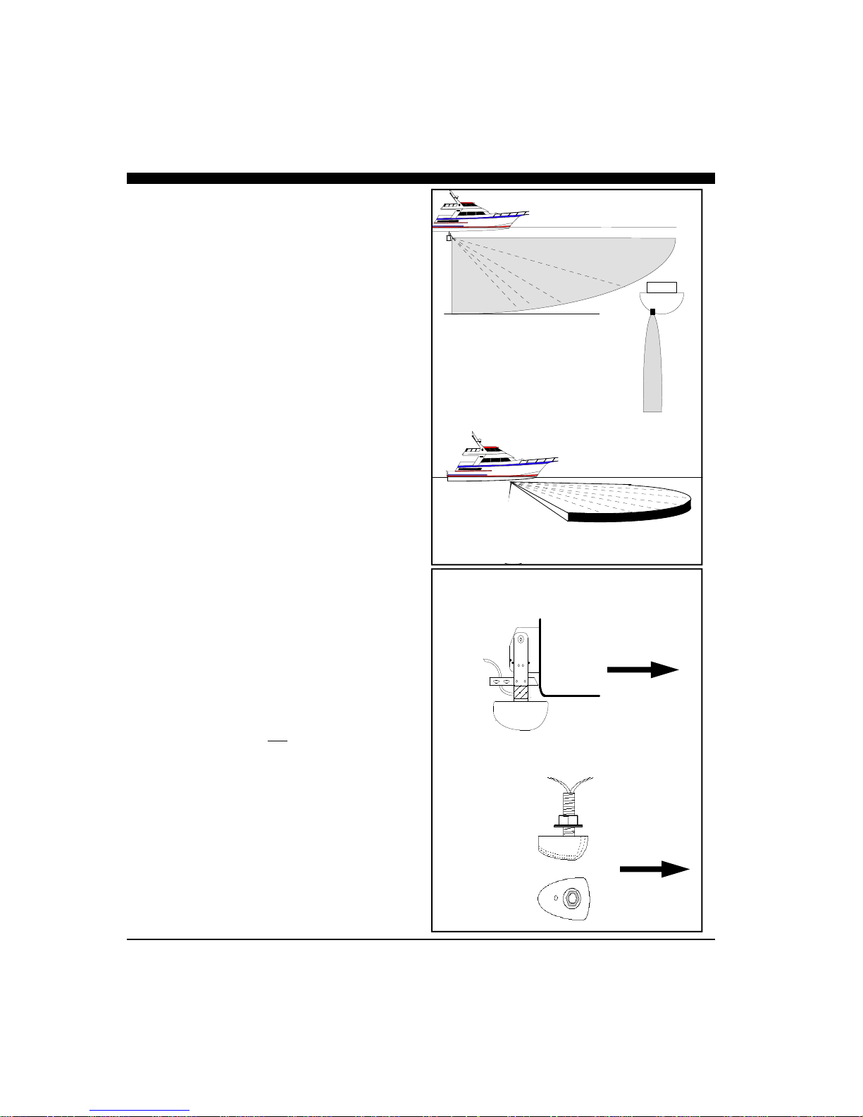
When selecting the transducer type and hull location
for the transducer(s) keep in mind the primary rule for
transducer operation. This is: the transducer can
function as long as it has an unobstructed forward
view and has smooth flowing non-aerated water
surrounding it.
♦
Do not cut or splice your phased array transducer
cable or removing the 9-pin connector as it will
void the transducer warranty.
♦
On both the thru-hull and transom mount transducers the blunt end is the forward end! See
sketch at right.
♦♦♦♦
If you need a longer length cable than comes
with the transducer (30’), then purchase the
optional extension cables, Interphase Part # 040014-008R for 30’ or 04-1014-007R for 10’
lengths. Total transducer cable lengths over 60’
are not recommended as they will decrease the
effective power and depth range.
♦
Choose a location where there is the least
amount of acoustic noise, air bubbles or
turbulence caused by the boat’s movement. The
transducer should not be located nearby or
especially directly behind the propeller.
♦
Choose a location where the transducer can be
mounted so that it will be level to the water’s
surface and will not be tilted to either side.
Otherwise the transducer will not scan from the
surface ahead to directly beneath the boat.
♦
DO NOT install a bronze transducer housing
directly into an aluminum or steel hull because
electrolytic corrosion will occur. Consult your
boat-yard for more information on how to
properly install transducers into these types of
hulls.
♦
DO NOT allow any solvents i.e. gasoline, acetone to come in contact with the transducer head
unit as this may dissolve the urethane material.
In addition, DO NOT force the cable by pulling
on it. This may cause damage to the internal
transducer wiring.
Scanning Directions.
Vertical Scan mode
shown above and
Horizontal Scan
mode below
Transom Mounted Transducer
Thru-Hull Transducer(s)
Side View
Top View
Forward
Forward
9

Suggested Thru-Hull Transducer Locations
Fin Keel
~ 1/3 L
L = waterline length
Displacement Hull
Planing Hull
Thru-Hull Considerations
Thru-hull transducers are for boats that exceed 40MPH
and /or have inboard motors. Transducer placement
depends on boat size, speed, hull configuration and
sonar application. On displacement hulls, the
transducer is generally located between 1/3 and 1/2 aft
of where the bow meets the water line. This is the
farthest forward the transducer should be mounted. It is
important that the transducer be below turbulent aerated
water created by the bow and does not come out of the
water during normal operation or when the boat is
pitching in a seaway.
Make sure the transducer has a clear view ahead and
that there are no forward hull obstructions that can
cause any turbulence in front of the transducer.
Mount so the transducer(s) bronze stem is within approximately +/- 5 degrees of vertical to insure scanning
in the proper directions. Most vessels will require a
fairing block to compensate for the angle (dead-rise) of
the hull.
Special Thru-Hull Mounting Considerations
On sailboats with a fin keel, the transducer is most
often placed at the leading edge of the keel and
sometimes faired into the keel. As this location may be
where the sling rests when hauling the boat, the
transducer may be placed on either side of the hull with
the foremost face of the transducer even with the
leading edge of the keel. Alternatley, the transducer
may be placed forward of the keel ahead of the lifting
strap location. This should not be ahead of 1/3 aft of
where the bow meets the waterline.
On planing hulls the transducer is typically placed near
the transom. This is to provide smooth flowing water at
the greastest speed. However, most planing hull boats
create transducer aeration when on plane regardless of
transducer location.
It should be noted that thru-hull transducers can effect
boat performance in two important ways. The first
concern is cavitation created by the transducer that
causes reduced engine performance by disrupting water
flow around the propeller. This is smoothed out by the
hull in some boats, but on planing hulls with the
transducer near the transom, the hull is not able to clear
the cavitation. The second concern is uneven drag on
smaller high-speed boats. This may occur when the
10

thru-hull transducer is mounted far off of the
centerline of the boat. At low speeds and on large
boats the effect is negligible. On smaller boats at high
speeds the drag can effect the steering. The effect
increases as the boat’s speed rises. Boats with trim
tabs can usually trim this out, but boats without trim
tabs may feel a pulling sensation toward the
transducer side of the boat.
A less intuative mounting location for the single thruhull transducer on a planing hull is on the centerline
just forward of midship. The goal in this mounting is
to place the transducer so that it is out of the water at
planing speed. As most transducers are aerated at
planing speeds, this removes the transducer from the
water flow preventing cavitation and steering
problems. Most applications for forward scanning
sonar occur when the boat is at low non-planing
speeds including fishing and navigating hazardous
waters. Under these lower speed conditions the
transducer is in the water.
Installing the Thru-hull Transducer
♦
Drill a 1/8” pilot hole from inside the hull to
assure access to tighten the housing nut and
clearance for the transducer cables.
♦
Use a 1-1/16” hole saw and drill the hole from
the outside. Sand or clean the area around the
hole, inside and outside to insure that the sealing
compound will adhere properly to the hull.
♦
Remove the bronze hex nut from the housing
and cable.
♦
Uncoil the transducer cable and thread it through
the hole into the inside of the hull.
♦♦♦♦
Apply a 1/8” thick layer of sealant on the upper
flat surface of the transducer, bronze alignment
pin and fairing block (if used).
♦
From the outside of the hull, push the housing
into the 1” hole. Twist the housing slightly to
squeeze out excess sealant. Carefully confirm
that the transducer is aligned so that the BLUNT
front end is pointed directly toward the front of
the boat.
♦
Install and tighten the bronze hex nut (allow for
swelling in wooden hulls) and remove excess
sealant from the outside to assure smooth water
flow over the transducer.
ULTRASCAN PC90
The single ULTRASCAN PC90 thru-hull
transducer (T1-I200-032) contains two phased arrays, one used to scan vertically and the other horizontally. The transducer has two cables, one connected to each array and each is color coded—green
for the vertical array and blue for the horizontal
array.
Because this transducer scans horizontally,
care must be taken to locate it at a position where it
can see 45 degrees either side of the bow (see sketch
at left with side and overhead views). The horizontal
scan plan is angled downward by 10º to minimize
surface clutter.
It can be mounted in front of a fin keel, or just
off to the side of the leading edge of the keel where
unobstructed forward vertical and horizontal views
are available.
On deep full keel vessels (trawlers, etc) it is
usually not possible to find a suitable location for a
single transducer with the horizontal scan. These
vessels should install the ULTRASCAN PC180 system with two transducers.
ULTRASCAN PC90—90-Degree Vertical and 90-Degree Hori-
zontal Scan
11

Mount Transducer So Bronze Stem is Vertical
Waterline
Keep parallel
to waterline !
Hull
FORWARD
Transducer
BronzeHex
Nut
Waterline
Fairing
Block
Keep parallel
Hull
to waterline !
DANGER: Wood hulls and wood fairing blocks
will expand after the boat is put back into the water,
so it is important that the transducer be only handtightened until the wood fully expands. Otherwise
the wood fairing block may crack.
DANGER: Be sure to check for leaks when the
boat is placed in the water. Allow at least 24 hours
after installation for any leak to appear.
Nearly all vessels have some dead rise angle at the
transducer mounting location. If the thru-hull
transducer were mounted directly to the hull, the
sound beam would be tilted off the vertical at the
same angle as the dead-rise, so most thru-hull
installations will require a fairing block to insure
the transducer is mounted properly.
If you’re installation requires a fairing block, you
may either have one made locally, or purchase a
molded plactic unit from Interphase or your
Interphase distributor. The Interphase part num-
ber for this fairing block is 40-2005-000.
NOTE
The flat top of the transducer must be
parallel to the water line. This will not
necessarily be parallel to the boat’s hull.
Boat’s
Hull
Underwater Sealant
Transducer
12

Transom Mount Considerations
Transom mounted transducers are intended for low
speed boats with external props. Boats with inboard
motors and boats that regularly exceed 35MPH can
not use transom mounted transducers. This is because
with inboard motors the prop is located in front of the
transom transducers and create aeration and excess
turbulence.
I/O motors where the prop is aft of the transom do
not create this situation, but be careful that the
driveshaft of the I/O does not block the forward
horizontal scan. Boats that exceed 40MPH run a risk
of having the transom mounted transduers torn free
of the transom. The transom mounted transducers are
not designed to be used at these speeds.
Transom mounted transducers are mounted on kickup or break-away brackets. This allows the brackets
to kick up at about speeds above 35-40MPH or if
they strike an object. Once kicked up, the transducers
must be manully reset in order to function.
Transom Transducer Kick-Up
Bracket
The transom transducer is attached to the boat with a
heavy-duty stainless steel kick-up bracket to provide
protection against impact. When the transducer
strikes an object, or the water force exceeds the
resistance of the bracket, the transducer automatically
kicks up and becomes non-operational. The bracket
does not automatically reset at lower speeds. The
transducer must be manually returned to its
operational position.
Special Note: The kick-up feature is designed as a
safety consideration to prevent the transducer from
being removed from the boat due to impact or
excessive speed. The kick-up bracket is not designed
for repeated kick-up or to be pulled up manually
during loading and unloading from boat trailers.
Tests have shown that the bracket can kick-up as
many as 30 times before there is a negative effect on
the bracket. Repeated kick-up will cause the
transducer to kick-up at progressively lower speeds.
Excessive kick-ups can cause the transducer bracket
to fail. Brackets that fail due to repeated kick-up are
not covered under the transducer warranty.
If the transducer must be kicked up for installation,
Transom Mount Bracket in Released Position
Note: Will
Not Work at
Speeds Above
35 MPH
Suggested materials required for installation:
♦
capacity of 10mm (3/8”) or larger.
♦
transom hole to route cable and
connector
♦
♦
♦
♦
Variable speed electric drill with a chuck
Hole saw or spade bit 19 mm (7/8”) for
Chamfer bit or 6 mm (1/4”) drill bit
Drill bit No. 28 or 4 mm (9/64”)
Drill bit 3 mm (7/64”)
Marine bedding/sealing compound
13

Twin Outboards
Transom Mount Locations
Cables
Transducers
Cables
Rear
View
Rubber
Grommet
Fasten Spray Shield
with 4 screws & nylok
washers as shown
Spray
Shield
Waterline
Bracket
Axle
18 - 24"
Fasten Spray Shield
with 4 screws & nylok
washers as shown
Spray Shield
Transducer must be
mounted vertically
Mounting
Bracket
Boat Hull
Waterline
Side View
boat service or loading, the nylok nut on the end of
the bracket axle can be loosened. Tighten the nut to
50 inch pounds of torque before operating the boat.
through the spacer.
Note: The Forward Horizontal Transducer must be
able to scan beneath the hull. The deadrise angle of
the hull must be less than 10 degrees in order for the
forward horizontal scan to sweep beneath the hull.
Alternately, the transducer can be mounted at or
below the lowest point on the hull.
The transducer can be installed on either side of an
outboard or inboard/outboard engine, or between twin
outboards. For single engine installations, normally
18” to 24” outboard of the propeller center line is
acceptable and the down stroke side of the propeller is
preferred. Choose a location where water flow is
smoothest. For dual engine installation, just off the
center line is usually acceptable.
Because the transducer rotates back and upwards
when the bracket releases, it must be mounted in a
location where there is sufficient clearance and
headroom to allow the full release.
Attach the Transducer & Spray Shield to the
Bracket
Locate the Stainless Spray Shield inside the
transducer’s stainless mounting ears. Make sure the
spray shield is orientated as shown in sketch below.
Then, assemble the stainless kick-up bracket to the
transducers using the 4 screws, washers and lock nuts
provided. Place the rubber grommet around the
transducer cable and slide it into the slot in the spray
shield. The bracket arms must be mounted outside the
stainless steel mounting ears of the transducer. Do not
fully tighten the lock nuts at this time. Tighten them
after the transducer is mounted and the spray shield is
positioned.
Position the transducer so that it is perpendicular from
side to side and make sure the wider blunt end is
pointed towards the front of the boat.
Mounting the Transducer to the Boat
After you have selected the optimum mounting
location and have assembled the mounting bracket to
the transducer, mount the bracket onto the hull as
shown on the right.
Make sure to position the transducer so that it is level
in the fore and aft direction and so it will look straight
14

down. Check the location of your boat’s waterline
and position the flat top surface of the transducer so
that it is parallel to the waterline as shown below.
Note: If the transducer is not mounted so that its fore
and aft direction is parallel to the surface, then the
forward looking display will be distorted and flat
bottoms will appear to be slanted upwards or
downwards. After mounting the transducer and
actually using the ULTRASCAN on the water, you
may need to readjust the transducer’s mounting for
optimum performance.
Bracket Axle Assembly
On some boats it will be neccessary to remove the
Bracket Axle during installation. See the diagram to
the left and instructions below for details on
assembling the axle.
1. Place one stainless steel washer onto the axle
against the hex end.
2. Place one small stainless steel spacer against
washer.
3. Slide two urethane spacers over the small steel
spacer.
4. With the transducer bracket in place, align the long
stainless steel spacer with the mounting holes of the
mounting bracket and slide the axle in place.through
the spacer.
5. Place one small stainless steel spacer against the
transducer bracket.
6. Slide two urethane spacers over the small steel
spacer.
7. Place one stainless steel washer onto the axel
against the urethane spacer.
8. Place the nylon nut onto the threaded end of the
axel and tighten to 50 inch pounds. If you do not
have a torque wrench, tighten until the nut will not
turn easily. The stainless steel spacers should prevent over-tightening.
Bracket
Axle
Nylon
Nut
5
8
7
6
Kick-up Bracket Replacement Parts
If during installation parts are somehow lost are
damaged, they can be replaced as follows:
Part# 17-0088-008 - Spray Shield Kit - Includes:
Spray Shield, four Mounting Bolts and Nuts, Rubber
Grommet and four Large Mounting Screws.
Part# 17-0089-008 - Transom Transducer Hardware
Kit - Includes: Complete Bracket Axle Assembly and
four Large Mounting Screws.
Part# 17-0056-008 - Kick-Up Bracket Assembly Includes: Complete Bracket Axle Assembly, four
Large Mounting Screws and the Stainless Steel
Mounting Bracket.
4
2
1
3
15

2 Amp Slo-Blow Fuse
Water
Ground
ULTRASCAN
INTERPHASE
Switch or
Breaker
10-36
VDC
GROUND
Ultrascan Beam-
former Module
Transducer (single thru-hull shown)
Beamformer Installation
The red box that came with your Ultrascan PC90
system is called the Beamformer Module. It houses
the transmitters and receivers that communicate with
the transducers. The Beamformer Module must be
connected by an RJ45 Ethernet cable to your shipboard PC or PC network, to the transducers and to a
source of 10 to 36 VDC power.
1) Select a location to mount the Beamformer
Module. Keep in mind that the unit must be
protected from from moisture and extreme
temperatures. Also, you will need to route the
Ethernet cable, the power cord and transducer
cables to the location that you choose.
2) Connect the two-pin plug on the end of the
power supply cable to the power supply jack
located at the front of the Beamformer Module.
Connect the red wire to a switch or breaker con-
nected to your ships positive (+) battery supply.and the black wire to the negative of your
boat’s battery. To prevent accidental damage—
it’s recommended that an inline slow blow 2
Amp fuse also be inserted in the positive lead.
3) Connect one end the Ethernet Cable to the Red
Box and the other to the Ethernet connector on
your PC or to an Ethernet connection on a network switch or router.
4) Connect the two transducer wires to the
matching ports on the back of the Beamformer
Module. They are color coded as follows:
Cable label Port label Color
HORZ HORZ Blue
VERT VERT Green
5) The Ultrascan also includes a ground screw just
to the right of the red data LED. Grounding the
case to a good water ground (engine block,
bonding system, thru-hull, etc) is recommended
as it will help minimize interference from surrounding sources of noise.
16

Software Installation
The Ultrascan PC90 software includes a group of
program files and a demonstration recordings. These
files will all be automatically copied to your computer’s
hard disk during installation.
The total size of the Ultrascan PC90 installation is
about 5 megabytes. We recommend that you make sure
that there is at least 15 megabytes of free space on your
hard drive before you begin the installation. If you plan
to save screen-captured images or record raw sonar
data, you will need additional space. We recommend
beginning with a minimum of 100 megabytes of free
space.
Ultrascan PC90 will run on a computer with Microsoft
Windows XP, Vista or Windows 7. Take the
following steps to install Ultrascan PC90 on your
computer:
1) Exit all programs that are currently running.
2) Insert the Ultrascan PC90 CD Disk into your
computer’s CD drive..
3) Follow the Setup instructions in each dialog box
that is displayed. Click the Next button to accept
the defaults.
The dialog box (shown at right) will prompt you to
accept the default destination folder for the Ultrascan PC90 files or select a different folder.
The dialog box in the lower right will ask whether
you want to create a desktop icon or a Quick
Launch icon. Most users choose to create an
Ultrascan icon on their desktop.
Ultrascan PC90’s Operating Software is
located on a CD which is included with
your system. The latest software is also
available for download at from the
Interphase website at:
www.interphase-tech.com
17

Connecting to a PC
Set Your Computer’s Ethernet Port’s IP
Address to 192.168.1.3
Using the Ethernet cable provided, connect the Ultrascan PC90 to your Computer’s Ethernet port.
The Ethernet port on the Computer should be set to a
static IP address of 192.168.1.3.
To set your computer’s IP address in Windows Vista,
click START —> CONTROL PANEL —> NETWORK AND SHARING CENTER. Then click on
MANAGE NETWORK CONNECTONS
Right click on the Network Connection that needs to
be changed (usually the local area connection) and
then select PROPERTIES as shown at top left.
Select INTERNET PROTOCOL VERSION 4(TCP/
IPv4)
And the click on PROPERTIES as shown at mid left.
A pop-up window like that shown at bottom left will
appear. Choose “Use the following IP address”, and
then enter 192.168.1.3 for the IP address, and
255.255.255.0 for the Subnet mask. Click OK to save
your settings and exit the Local Area Connection
Properties.
18
Connect to Ultrascan Beamformer
After setting your PC’s IP address, turn on power to the
Ultrascan PC90. After a few seconds the green power
light will glow.
Wait 30 seconds, then open the Ultrascan PC90 computer
software.
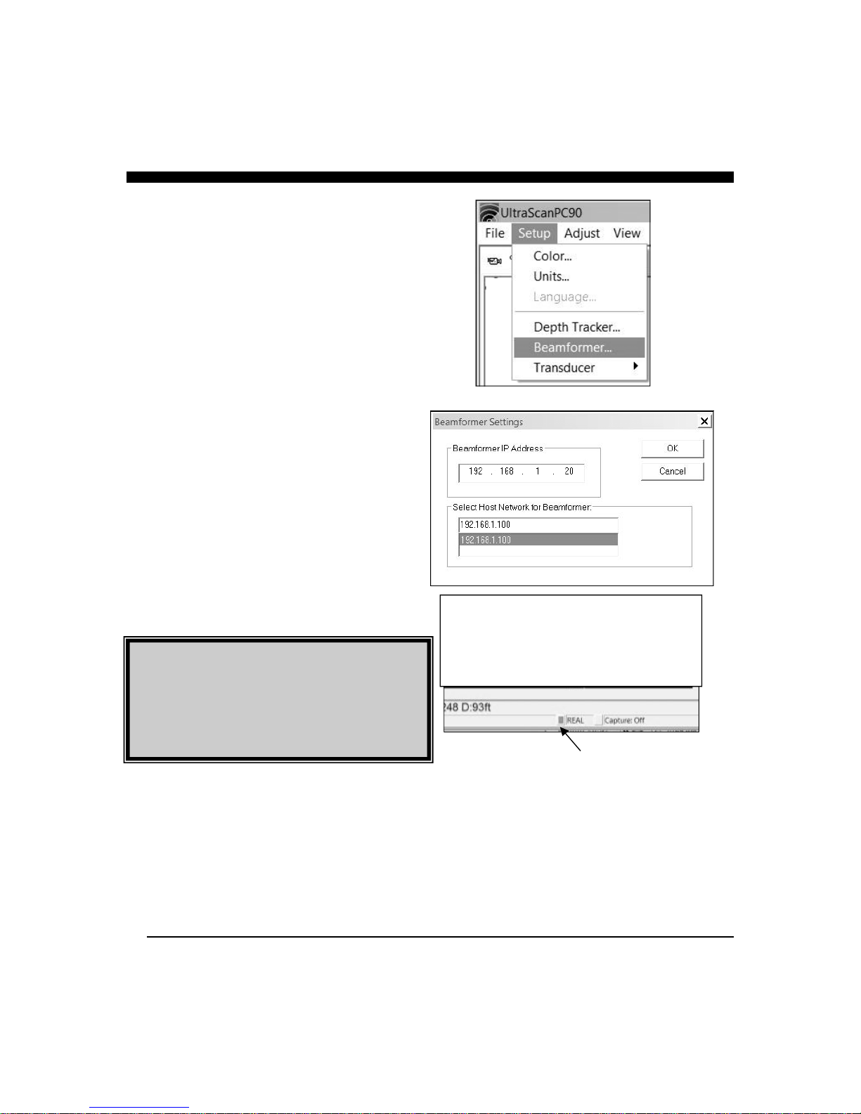
From Ultrascan PC90’s menu, choose SETUP—
>BEAMFORMER, as shown at right. The Beamformer
Settings pop-up window should appear as shown at right.
Enter Beamformer IP Address of 192.168.1.20, and in the
lower section of the window, highlight your computer’s
IP port address which you previously set to 192.168.1.3
Press OK to close the beamformer settings window.
The Orange light on the Ultrascan Beamformer Module
should light when a proper connection between the Beamformer and PC is made.
The Ultrascan PC90 should now be communicating with
your PC. You should see a red/green blinking indicator
on the bottom toolbar of the Ultrascan PC90. Also, the
word “PLAYBACK” will be replaced with the word
“LIVE”, as in the picture at lower right.
Ultrascan PC90’s Beamformer Module is shipped
with the default IP address of 192.168.1.20.
If needed, the IP address can be changed by using
the Ultrascan Web Server. For more information,
see page 50
PING LIGHT—BLINKS
RED/GREEN
WHEN
COMMUNICATING
WITH BEAMFORMER
19

3 Quick Start
Parameter Menu Default Type
Auto-Screen Capture File Off Hard
Running Ultrascan PC90
To start the Ultrascan PC90 system, turn on the
switch or breaker that provides power to the beamformer module.. Then run Ultrascan PC90 by
clicking on the Ultrascan PC90 icon on your computer’s desktop.
If all components have been installed and all cables
are connected, and the Beamformer Module is on,
Ultrascan PC90 will immediately begin to collect and
display data. Take the following steps to adjust Ultrascan PC90 for basic operation:
1) Set defaults as described below. Be sure that
Auto Gain and Auto Range are off.
2) Select a display (see p.26).
3) Select a range setting that is slightly greater than
your current water depth (see p.30).
4) Adjust the gain by first turning it down until little
imagery is visible on the display. Increase the
gain until you begin to see noise, then decrease
the setting by one (see p.30).
Color Setup Normal Soft
Units Setup Feet Soft
Surface Masking Setup Off Hard
Depth Threshold Setup Normal Hard
Auto Gain Adjust Off Hard
Gain Adjust 10 Soft
Auto Range Adjust Off Hard
Range Adjust 25 Feet Soft
Alarm Adjust Off Hard
Defaults
The default settings for many of the Ultrascan PC90
features are shown in the table at left. Hard defaults
are always reset when you exit the program. Soft
defaults are recommended settings for general
operation.
If you are running Ultrascan PC90 for the first time, it
will start with the default settings as shown at left.
Change the settings by selecting the appropriate
command from the specified menu.
Demo Recordings
Ultrascan PC90 installation software includes several
actual recordings which can be played back and used
to demo many of the Ultrascan’s features.
20
Running in PLAYBACK mode will allow you to
practice and to get a feeling for the Ultrascan PC90’s
many features before actually using the system in real
situations on the water. Note: when you play back the
recording, you will not be able to change the range.
However, you will be able to use most of the other
features.
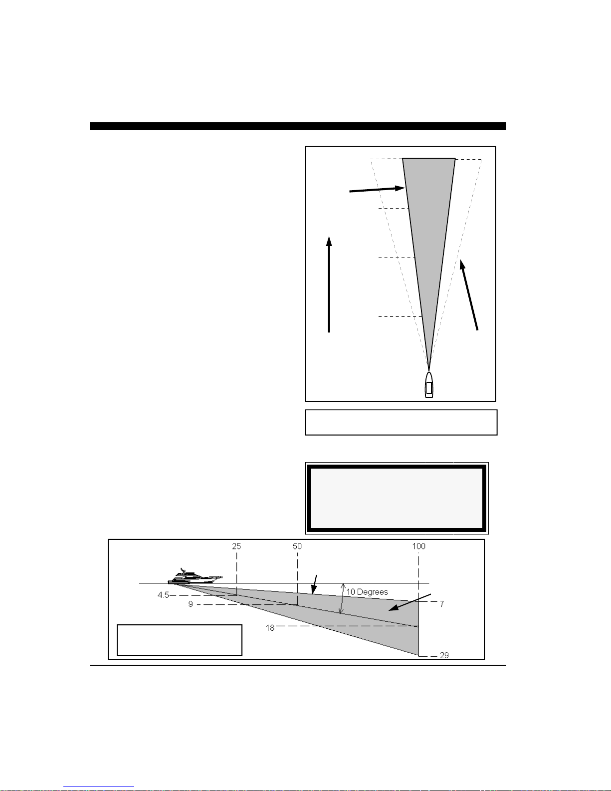
12 Degree
Cone Angle
1000
750
210
158
Beam Width
The Ultrascan PC90’s Beam Width is approximately
12 degrees in both the vertical and horizontal scan
modes. The diagrams at right and below show the
approximate width of the vertical and horizontal
scanning beams at different distances from the boat.
The Ultrascan PC90 will generally image features
within the shaded areas.
The Ultrascan PC90 horizontal scan is oriented
approximately ten degrees down from horizontal (see
the diagram below). Thus, the depth to the center of
the beam is approximately 18 percent of the distance
from the boat.
500
250
Distance
Forward or
Below Boat
105
53
Ultrascan can
typically see
targets within
this area.
Width of 12 Degree Acoustic Beam
TIP
The width of the 12-degree main beam is
approximately 1/5 of the distance from the boat
Distance Forward
Depth
Width of Acoustic Beam
Horizontal Scan
21
12º Beam
Width
Ultrascan
PC90 can see
targets within
this area.

4 Basic Operation
Toolbar
Screen Capture Alarm Reset
About Ultrascan
Vessel Position
Units
Water Depth
Range
Latitude
Cursor Position
Bearing
Depth
Longitude
Getting Started
This chapter will help you to learn the modes of
operation and the basic features of the Ultrascan
PC90 system. For more experienced users, this
chapter can be used as a reference. Read Chapter 3
Quick Start to learn how to start the Ultrascan PC90
software.
Ultrascan PC90 is a Windows application with a
standard Windows menu structure. The Ultrascan
PC90 screen includes a data display window as well
as the Toolbar and the Status Bar.
The Toolbar and Status Bar can be toggled on or off
via the View Menu.
The Toolbar
The Toolbar enables quick access to features which
are used often including:
• Screen Capture, which saves the current screen
to the hard disk (see p.35),
• About Ultrascan PC90, which displays the
software version number, and
• Alarm Reset, which turns off the depth alarm
after it has been triggered (see p.31).
The Toolbar also includes three digital data displays
including, from left to right across the screen:
• Depth beneath the transducer calculated by Ultrascan PC90 with the current units,
• Vessel Position information if it is available (e.g.
38º 58.95N 121º 58.49W; refer to the discussion
of NMEA navigation input in Chapter 5
Advanced Operation), and
• Cursor Position. Depending on which display is
active, the cursor position will include range (R),
bearing (B, negative to port, positive to
starboard) and/or depth (D). When the cursor is
outside of a data display area, the position box
displays the current range and gain settings (e.g.
Rnge=25ft; Gain=20).
22
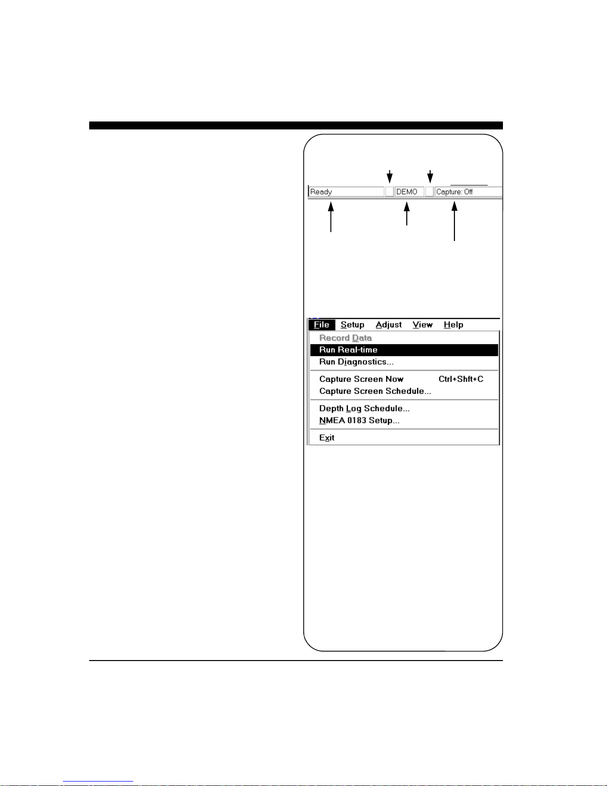
The Status Bar
The Status Bar displays current information about
Ultrascan PC90 operation including:
• Status Message,
• Ping Light, which alternates between red and
green on consecutive pings,
• Mode, Live or Playback,
• Capture Light, which flashes blue during a
screen capture, and
• Capture Status, showing the screen capture
schedule and remaining hard disk space.
Operating Modes
Ultrascan PC90 operates in one of two modes: Live
and Playback. If all components have been installed,
all cables are connected and the Beamformer Module
is on when you start the software, Ultrascan PC90
will immediately begin to collect and display data in
Live Mode. If a recording is being viewed the unit
will be in the Playback Mode.
Use the File Menu to switch between Playback and
Live modes.
Playback Mode
In Playback Mode, Ultrascan PC90 will continuously
display the recorded data that was installed with the
software or other user recorded videos. Ultrascan
PC90 will look for the recorded data in a folder called
‘Data’ in the Ultrascan PC90 program folder. If no
recording is selected, the display window will remain
blank.
Live Mode
When the Live Mode is selected, Ultrascan PC90 will
attempt to find the beamformer module. When communications begins the ping light on the lower toolbar
will blink between red and green.
Ping Light Capture Light
Status Message
Status Bar
Mode
Capture Status
23
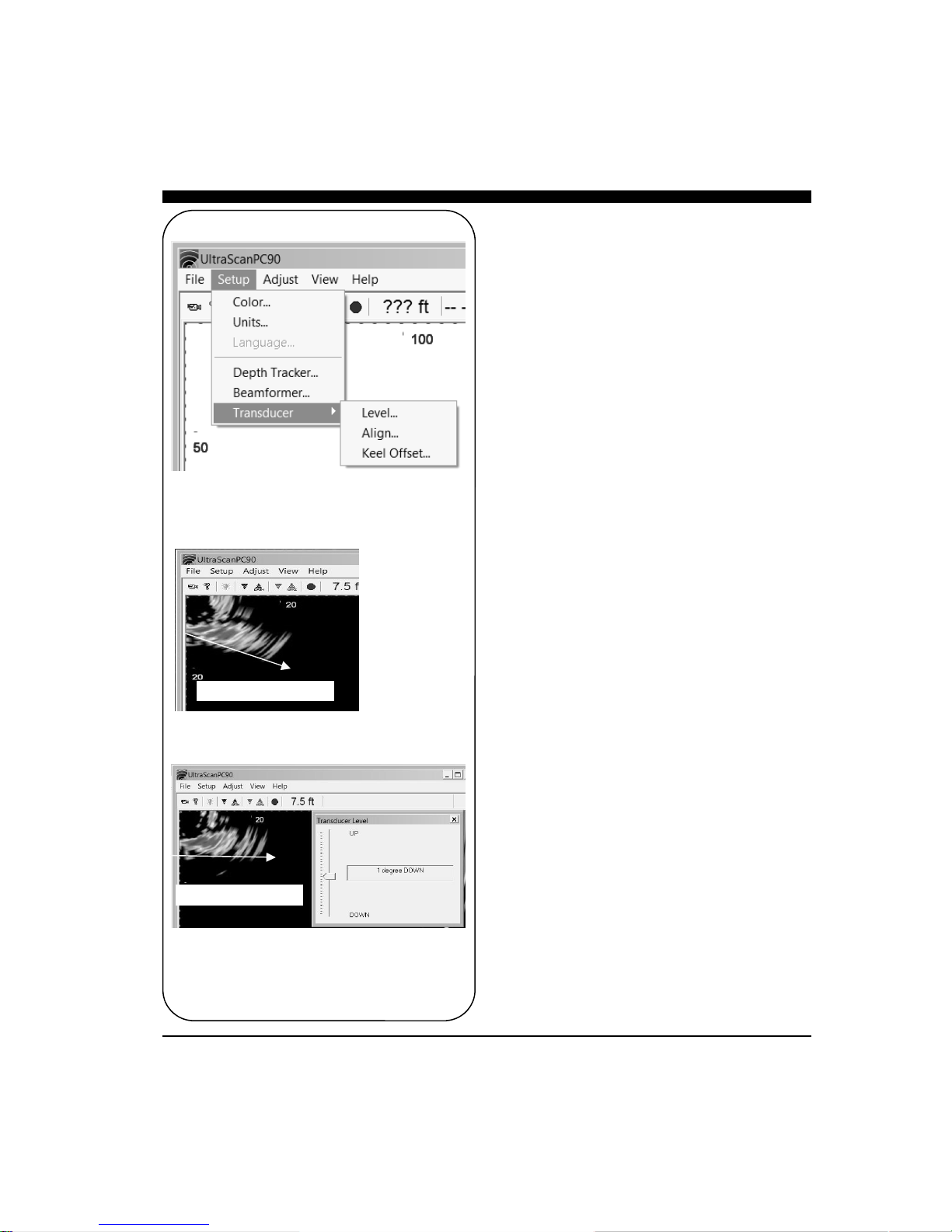
Before Level Adjust
After Level Adjust
Setting System
Parameters
There are several system parameters that you will
usually need to set only once. Set these parameters
using the Beamformer and Transducer commands on
the Setup menu.
Beamformer I.P. Address
The default I.P. address for the Ultrascan beamformer
module is set to 192.168.1.20. Make sure your computer’s network I.P is set to the same subnet mask (i.e.
192.168.1) and the device number is different than the
beamformer's “.20”. For example, set your computer’s
IP network address to 192.168.1.3 or 192.168.1.4, etc.
Transducer Mount Corrections
The Ultrascan PC90 software can compensate for minor
transducer misalignments. These are important
corrections, particularly if Ultrascan PC90 is being used
as a collision avoidance aid. For example, if the
vertical scanning transducer is tilted forward, a level
bottom will appear to be getting shallower at greater
distances. If it is tilted back, a level bottom will appear
to be getting deeper.
Level Adjustment
In case the vertical scanning transducer has been
mounted with a fore or aft tilt, Ultrascan PC90 can
compensate for up to 14 degrees of tilt in either
direction.
To set the Transducer Level parameter, Run Ultrascan
PC90 when the boat is over a known level bottom. The
vertical display should also appear level. If, however,
the bottom display is slanted upward (as shown in the
“Before Level Adjust” picture at left), it means that the
transducer was mounted with its nose pointing down
slightly. If the bottom slopes upwards by 10 degrees,
the Transducer Level correction should be 10 degrees
DOWN. If the bottom slopes downward, adjust the
Transducer Level in the UP direction to compensate.
After setting the Transducer Level, view the VERT
display to verify the correction.
24
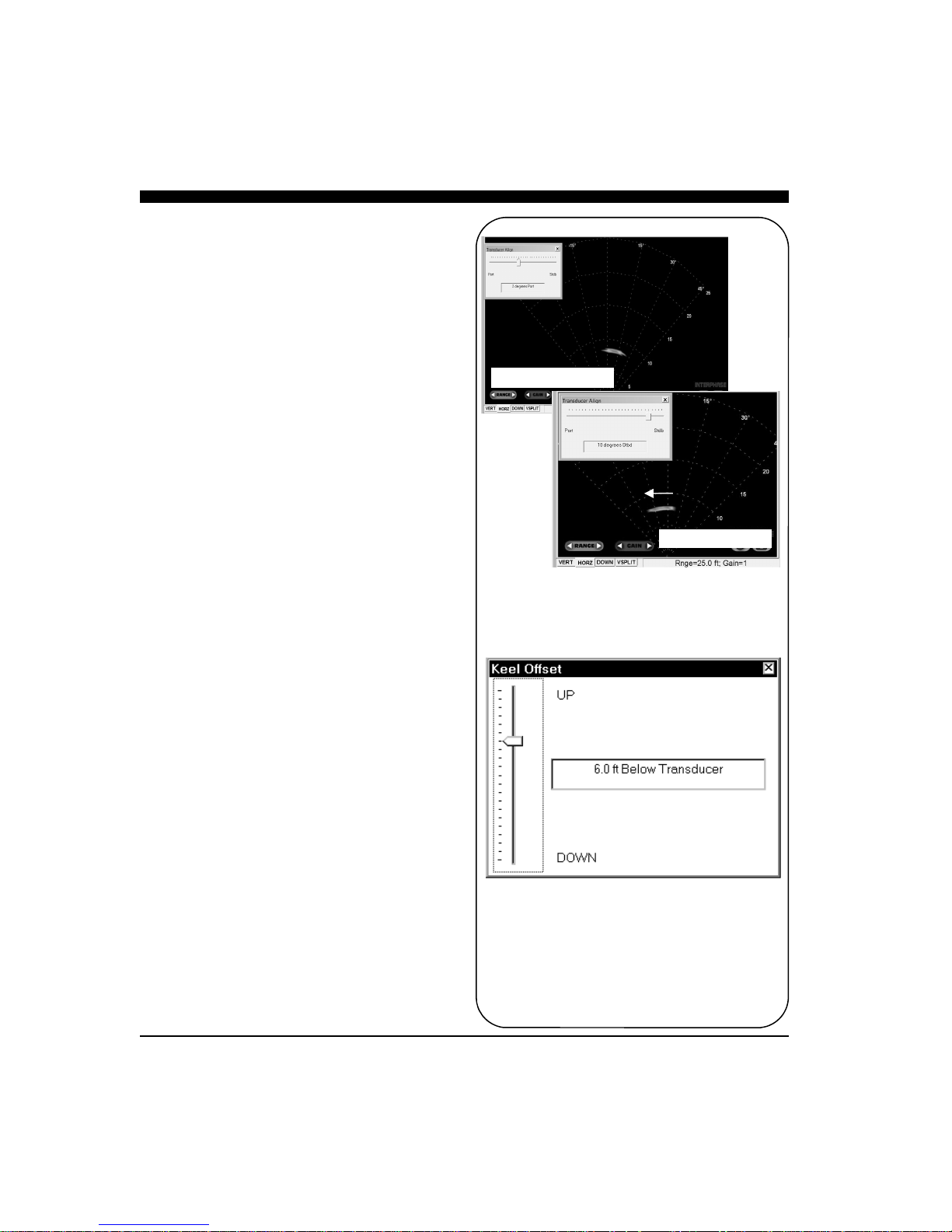
Align Adjustment
In case the horizontal scanning transducer has been
mounted such that it points in a direction other than
dead ahead, Ultrascan PC90 can compensate for up to
14 degrees of misalignment in either the port or
starboard direction.
To set the Transducer Align correction, point the boat
directly toward a target (such as a piling, etc.) The
target should appear at the center of the horizontal
scanning display. If, however, the target is off to the
port (as shown on the “Before Align Adjust” picture
at right), it means that the transducer was mounted
pointing slightly in the starboard direction. If the
target is offset to the port by 7 degrees, the
Transducer Align correction should be 7 degrees
Stbd. If the target appears off to the right (Stbd),
adjust to the Port direction to bring the target back to
the center position.
After setting the Transducer Align, view the HORZ
display to verify the correction.
Keel Offset
If the transducer(s) are mounted in a position above
the deepest point of your boat’s keel, Ultrascan PC90
can automatically adjust the depth scale bars to
compensate for the offset. This will allow you to
always work with depths that are relative to the
bottom of your boat’s keel.
Move the slide bar to specify the depth of the keel
beneath the transducer(s).
Before Align Adjust
After Align Adjust
25

Displays
Ultrascan PC90 has four different scanning sonar
display windows. They are VERT, HORZ, DOWN,
and VSPLIT, as shown at right. View a display by
clicking on its tab at the bottom of the window.
Each display fills the current Ultrascan PC90
window. Change the size and/or aspect ratio of the
Ultrascan PC90 window by dragging the sides or
corners of the window.
Setting Color and Units
The color scheme and distance units can be changed
to suit your operating conditions and preferences.
Access Color and Units controls using the Setup
menu. Both parameters are consistent in Ultrascan
PC90 regardless of which scanning display window is
active. The units are also consistent in the depth
window but the color scheme of the depth window
cannot be changed.
Display windows can be viewed in one of three color
schemes:
• Normal, a color palette varying from light blue
through red on a black background which is
useful for operation in normal daytime
conditions.
• Sunny, a gray-scale palette on a white back-
ground which allows you to view contrast in
very bright conditions
• Night, black, dark red and bright red which
enable you to see contrast while preserving your
night vision.
Each display includes scale bars showing distance in
the selected Units. Units options include Feet, Meters
and Fathoms. The selected units are displayed in the
Status Bar for reference.
In the pop-up window shown at left, there is also an
adjustable slider labeled Noise Floor. When the
slider is at the bottom the Ultrascan will displays the
full dynamic range of echo signals Signal strength is
related to color with red being the strongest. Raising
the slider will eliminate the lower signal strength
colors (blue) which can help reduce clutter in shallow
water situations.
26

DISPLAY MODES
Vertical Display
Vertical Split-Screen Display
Horizontal Display
Downlooker Display
27

Scanning Directions.
Vertical Scan mode
shown above and
Horizontal Scan
mode below
VERT: Vertical Scan Display
The VERT display shows the image created by
the vertical scanning transducer elements. This
array scans through a maximum of 90 degrees in
a sector starting horizontally in the direction that
the boat is heading and ending vertically beneath
the transducer (see figure at left).
The vertical scan is shown with the transducer at
the upper left corner of the display window with
the selected range extending to the lower right
corner of the window. As a result, the scale bars
will usually indicate maximum distances that are
less than the selected range.
HORZ: Horizontal Scan Display
The HORZ display shows the image created by
the horizontal scanning transducer elements. This
array scans through a maximum of 90 degrees in
a sector centered about the boat’s heading and
tilted downward from horizontal by about 10
degrees (see figure at left, center).
The horizontal scan is shown with the transducer
at the bottom of the display window and the
selected range extending to the top of the
window, regardless of the window’s width. Thus,
data will be clipped on the sides of a tall, narrow
display (see figure at bottom left).
DOWN: Downlooker Display
The downlooker display shows the region directly
beneath the boat over time. The right edge of the
display always shows the most recent ping.
Since Ultrascan PC90 does not know boat speed,
the downlooker display cannot be used to
determine horizontal distances. Thus, there is no
horizontal scale bar in the downlooker display.
Ultrascan PC90 can only extract DOWN data
from the vertical array.
28

VSPLIT: Vertical Split-Screen
Display
The VSPLIT display shows downlooker data in the
left portion of the window and the forward vertical
scan in the right portion of the window. The
downlooker data occupies one quarter of the
horizontal dimension of the window and the vertical
scan occupies the remainder of the space.
Both portions of the display are equivalent in function
to the individual DOWN and VERT displays.
However, Ultrascan PC90 will always use the Gain,
Range and Alarm settings that are associated with the
vertical scan.
29

Adjusting the Gain and
Range
The Gain and Range adjustments are perhaps the
most critical features of Ultrascan PC90 in optimizing
the system performance for different operating
conditions.
Gain and Range can be set manually or, alternatively,
Ultrascan PC90 can set and vary the Gain and Range
settings automatically. It is important to note that
each scanning direction has its own Gain and Range
settings. To change the Gain and Range settings for
the current display, select Gain and Range... from the
Adjust menu.
Gain Adjustment
The Gain level controls the intensity of the signals
shown on the display by varying the amplification of
the sonar signals that Ultrascan PC90 receives. Click
on the Auto box to turn Auto Gain on and off. A
check in the box indicates that Auto Gain is on. The
default setting is off.
In the manual mode, Ultrascan PC90 allows you to
choose from 32 different Gain levels, numbered from
1 to 32. The default level is 16. Select the Gain by
sliding the pointer on the Gain bar. Level 1 provides
the smallest amount of Gain. At this level, the screen
will display little or no data. Higher Gain numbers
will brighten the display. The Gain level required to
see a specific target will vary with target range, water
clarity and background noise. In addition, Range
changes may also require changes in Gain.
In the Auto Gain mode, Ultrascan PC90 will adjust
the gain level automatically depending on the strength
of the sonar signal returns. Note that it is still
possible to make manual adjustments in the Auto
Gain mode, but any adjustments you make could be
changed by Ultrascan PC90.
Range Adjustment
The Range is the maximum distance at which features
will be displayed by Ultrascan PC90. In general,
features at greater distances will be less clearly
resolved. In addition, the water conditions will help
to determine the greatest distance at which Ultrascan
30

PC90 can accurately image features. Click on the
Auto box to turn Auto Range on and off. A check
in the box indicates that Auto Range is on. The
default setting is off.
In the manual mode, Ultrascan PC90 allows you to
choose one of twelve preset Ranges. Range can be
varied between 25 and 1000 feet, 8 and 300 meters,
or 4 and 160 fathoms. Select the desired Range by
sliding the pointer on the Range bar. The default
setting is the minimum range (25 feet).
In the Auto Range mode, Ultrascan PC90 will
adjust the Range automatically to keep the bottom
within the center three-quarters of the range scale.
If Ultrascan PC90 cannot find the bottom, it will
step through the Ranges until the bottom is found.
It is possible to make manual adjustments in the
Auto Range mode.
NOTE
Each Ultrascan PC90 gain setting is
actually a Time-Varied Gain (TVG)
curve which applies higher gains to later
returns. This is an important feature
which works to counteract the inherent
weakening of the acoustic signals with
distance from the transducer.
Leave the Gain and Range and/or
Alarm boxes open if you plan to make
frequent manual adjustments. Move a
box by dragging it to a desired position
TIP
Auto Gain and Auto Range are always
turned off when you exit Ultrascan
PC90.
NOTE
31
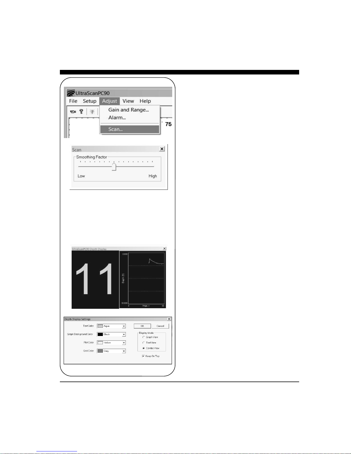
Display Smoothing
In turbulent or rough sea conditions, the picture may
become cluttered. To minimize random noise and
interference, use Ultrascan’s smoothing factor adjustment to average between multiple display frames.
Go to ADJUST—>SCAN as shown in the menu at
left to open a Smoothing Factor window with a horizontal slider control.
The default slider position is mid-range, For less
smoothing move the slider to the left or for more,
move the slider to the right.
Depth Window
In addition to the four scanning sonar displays, Ultrascan PC90 includes a separate depth window that
can be moved and resized to fill any portion of the
screen. Open the window by selecting Depth Display
from the View menu.
The depth window includes a large numerical display
as well as a graphical display of the depth over time.
The window stays open when the Ultrascan PC90
application is minimized. Note that, if you use AltTab to select Ultrascan PC90 from several
applications running under Windows, an open depth
display will remain in the background. Select Depth
Display from the View menu to bring the window to
the front.
32
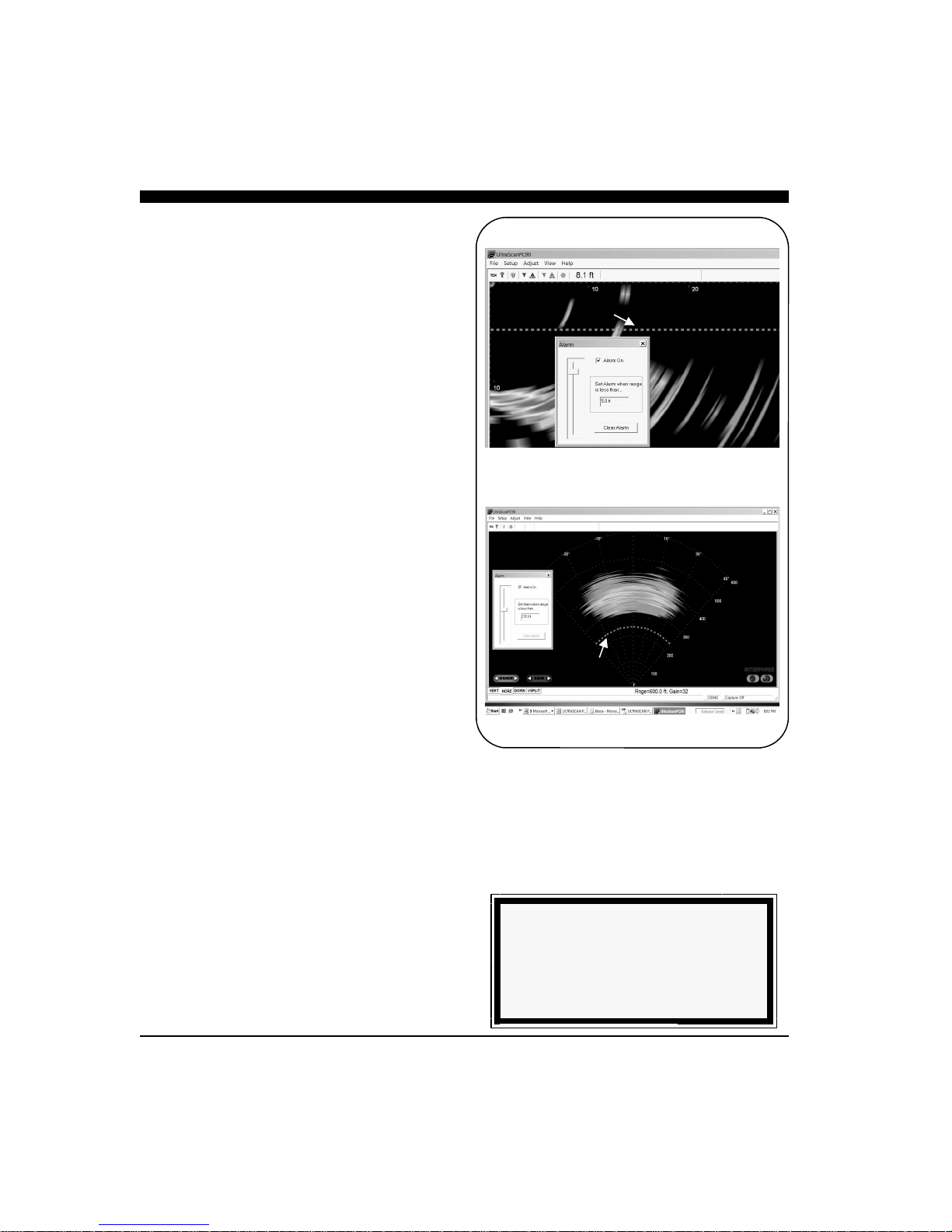
Using the Alarm
Ultrascan PC90 provides an audible alarm to alert you
to nearby and shallow features. VERT, HORZ and
DOWN displays use independent alarm settings.
VSPLIT and HSPLIT displays use the vertical and
horizontal alarm settings, respectively.
Change the alarm settings by selecting Alarm from
the Adjust menu. Turn the alarm on and off by
clicking on the Alarm On box. Select an alarm
distance by moving the slide bar.
The distance covered by the alarm will appear in the
scale bar of the display as a solid magenta bar, and a
magenta line or arc will cross the display at the
specified distance or depth. Vertical and downlooker
alarms are triggered whenever a solidly displayed
target appears shallower than the depth indicated by
the alarm bar. The horizontal alarm is triggered
whenever a solidly displayed target appears closer to
the boat than the range indicated by the alarm arc.
Once the Alarm has been triggered, it will continue
sounding until it has been reset. Reset the Alarm by
clicking on the Clear Alarm button in the Alarm box
or by clicking on the yellow light bulb in the Toolbar.
Vertical Alarm Bar
Horizontal Alarm Bar
NOTE
An alarm setting of zero is equivalent to
having the alarm off.
33

NOTE
Depth Tracker settings always return to
the defaults when you exit Ultrascan
PC90.
Adjusting the Depth
Tracker (Digital Depth)
With every vertical array ping, the Depth Tracker
attempts to find the bottom. The depth that is found
is displayed in the toolbar as well as the depth
window if it is open (see p.22 for a discussion of the
depth display). If the depth tracker cannot find the
bottom, a question mark will be displayed in the
toolbar. The tracked depth can be saved to a file and
sent out over a serial port. Refer to Chapter 5 for a
discussion of this utility.
If Auto Range is on, Ultrascan PC90 will use the
tracked depth to adjust the range (see p.30 for a
description of Auto Range). If the depth tracker
cannot find the bottom, Auto Range will step through
the available range scales until the bottom is found.
To adjust the parameters used by the depth tracker,
select Depth Tracker... from the Setup menu.
Surface Masking
The Surface Masking feature allows you to specify a
range near the water surface in which the depth
tracker will ignore any incoming returns. The default
Surface Masking is off.
Surface Masking is useful if there is a strong surface
return, abundant floating debris, bubbles under the
hull or surface bait schools. With blanking off in
such situations, the depth tracker could mistake these
shallow returns for the bottom.
The maximum masking range is about 10 feet, 3
meters, or 1.6 fathoms. Use the slide bar to select the
masking range. The selected masking range is shown
in all display windows.
Threshold
To avoid errant depth tracking on noise and
suspended features, the depth tracker applies a
Threshold. Normal is the default setting which
should be used in most situations.
However, if the gain is set so that the screen is dark,
revealing only obstacles and very bright mid-water
targets, the Low threshold setting may be required in
order to continue to track the depth.
34

Alternatively, if the gain is set high so that
everything is bright, the High threshold may be
necessary to avoid tracking depth on bait balls and
other strong mid-water returns.
Saving Data with Screen
Capture
Images displayed in Ultrascan PC90 can be saved
using the Screen Capture feature. There are four
ways to capture an image:
1) Select Capture Screen Now from the File
Menu.
2) Use the keyboard shortcut Ctrl+Shft+C.
3) Click on the Screen Capture button of the
Toolbar.
4) Use the Screen Capture Scheduler accessed
from the File Menu to automatically create
periodic screen captures.
Ultrascan PC90 will not carry out a requested or
scheduled screen capture if there is less than 20
megabytes of space remaining on your hard disk.
Whenever Ultrascan PC90 does a screen capture,
the screen capture indicator (to the left of the screen
capture status box in the Status Bar) flashes blue.
Each screen capture image is saved in the folder
specified in the Screen Capture Scheduler. The
default folder is the Data folder in the Ultrascan
PC90 program folder:
C:\Program Files\Interphase\Ultrascan PC90\Data
The Scheduler allows you to turn auto-saving on or
off (click on the box labeled Enable Screen
Capture) and specify the frequency of auto-saving.
Files are saved in the JPEG (*jpg) format and each
picture is approximately 40kB in size.
Screen Capture
File Name Format
20101118164240R0048G31.jpg
Year Range
Month Gain
Day
Hour Format
Minute (jpg)
Second
35
5 Advanced Operation
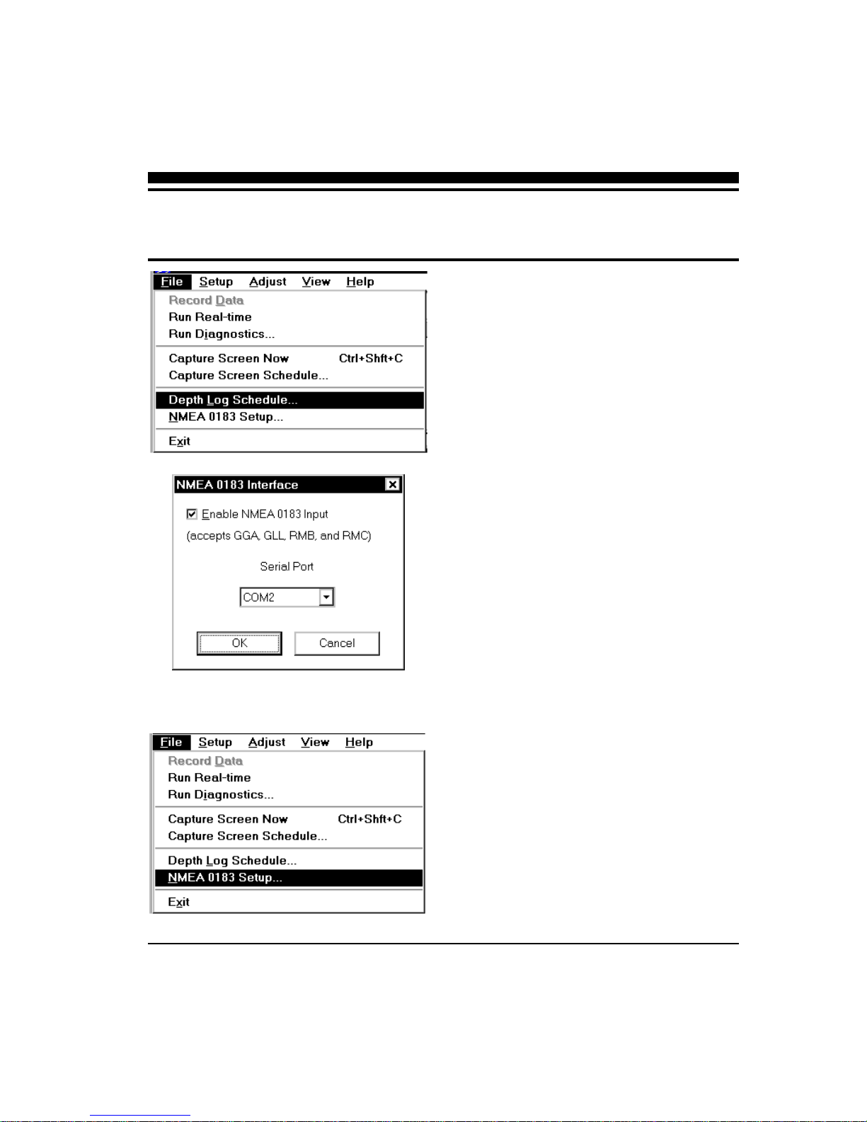
Working with NMEA
Navigation
Ultrascan PC90 reads standard NMEA 0183
navigation strings from a serial or USB port, extracts
the latitude and longitude and displays this
information in the toolbar.Ultrascan PC90 accepts
GGA, GLL, RMB and RMC strings. To activate this
feature, select NMEA 0183 Setup… from the File
menu, click in the check box labeled Enable NMEA
0183 Input and select the serial or USB port to which
navigation input is connected.
When NMEA 0183 input is enabled, the Ultrascan
PC90 will look for data coming from the serial or
USB port. If the NMEA strings are successfully
parsed, the Ultrascan PC90 will display the most recent latitude and longitude in the navigation box on
the toolbar. If no data is detected coming from the
serial or USB port, a series of dashes will be displayed in the navigation box. A blank navigation box
indicates that NMEA 0183 input is disabled.
Use the following connections to your serial port. If
you have a 9-pin serial port:
Pin#2 = RX = Out
Pin #3 = TX = In
Pin #5 = Ground
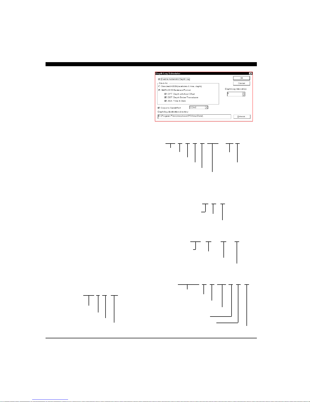
Logging Depth
Ultrascan PC90 can log the tracked depth in a file and
send it out over a serial port. To activate this feature,
select Depth Log Schedule… from the File menu and
click in the check box labeled Enable Automatic
Depth Log. Next, select a format for the logged depth.
Choose ASCII format or NMEA 0183 sentence
format. The ASCII format includes the date, the time
and the depth below the transducer in the current
Units.
For the NMEA 0183 format, any or all of three
sentence types can be saved. NMEA 0183 format
36
(and Position)
sentences begin with a dollar sign followed by the
two-character talker identification followed by the
three-character sentence type. The talker
identification for Ultrascan PC90 is SS, for
scanning sonar. Data fields in the sentences are
comma-delimited and the sentences end with a star
followed by the checksum. Ultrascan PC90 uses the
following three sentence types:
DPT - Depth with Keel Offset. This sentence
includes the water depth, in meters, relative to the
transducer followed by the offset from the
transducer in meters.
DBT - Depth Below Transducer. This sentence
includes the water depth in feet; the water depth in
meters and the water depth in fathoms, all
referenced to the transducer.
ZDA - Time and Date. This sentence includes, the
Universal Time Coordinated (UTC), the day, the
month, and the year, all in UTC, and the local zone
hours and minutes (Atlantic Standard Time is local
zone 05 hours, 00 minutes).
Once you have selected the depth log format, select
a depth log frequency interval in seconds. If the
frequency is set at 5, Ultrascan PC90 will log the
depth every 5 seconds. Ultrascan PC90 will always
log the depth to a file named with the current local
date (year month day) and a file extension of .dep
(e.g. 20100401.dep). By default, the file will be
saved in the Ultrascan\Data directory
(D:\Program Files\UltrascanPC90
\Data\).
Depth Log
File Name Format
ASCII Depth Format
2010/03/31 16:43:29.01 12.2 ft.
Year
Month Depth
Day
Hour Units
Minute
NMEA Sentence Formats
$SSDPT,4.2,0.0*46
Water Depth (m)
Keel Offset (m)
Checksum
$SSDBT,13.0,f,4.0,M,2.2,F*27
Depth in feet
Depth in meters
Depth in fathoms
Checksum
$SSZDA,004635.18,01,04,2010,08,00*79
20100401.dep
Year
Month
Day
Depth file extension
UTC (hhmmss.ss)
Day (UTC)
Month (UTC)
Year (UTC)
Local zone hours
Local zone minutes
Checksum
37
$GPGLL,2457.250,N,12120.714,E,104439.02,A*61
Latitude, N/S
Longitude, E/W
UTC(hhmmss.ss)
Status
A=data valid
V=data not valid
Checksum
If you wish to save to another directory, specify the new
directory in the Depth log destination directory box. To
send the depth information out a serial port as well,
click in the box labeled Output to Serial Port and select
a serial port from the pull-down menu. Ultrascan PC90
will automatically configure the protocol of the selected
serial port to the NMEA 0183 standard.
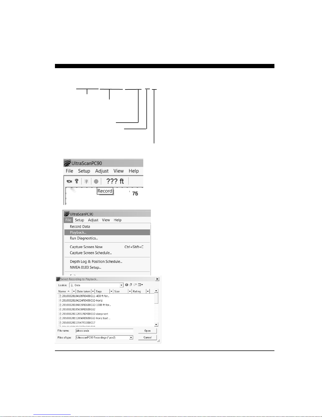
Recording Live Data
Ultrascan PC90 can record the actual raw sonar that’s
transmitted over the Ethernet from the beamformer
module to the PC. The data can be saved and later
played back through the Ultrascan PC90 program.
The Ultrascan will only record raw video data when the
PC is actually receiving it from the beamformer module. Therefore, the Record button will not work when
viewing previously recorded data.
When video recording of the raw data is available, the
record button will be a bright red color.
To start the recording, depress the RED record button.
When recording, the bottom toolbar will say RECORDING and the small box to the right will turn a
blue color as shown at right.
Recording will automatically be saved in the Program
Files/Ultrascan PC90/Data file, unless another folder
has been chosen in the record schedule file.
To replay the raw data file, got o FILE—>PLAYBACK
and choose the desired file. When running the recorded file, you can make adjustments to most of the
controls—except for the range. Also, if the recording
was made in the vertical mode, it should be played back
in the vertical mode, etc.
If you are viewing a recording and wish to change to a
different recording, you must first go to FILE—>RUN
LIVE, and then go back to FILE—>PLAYBACK to
choose a different file.
38

Using the Diagnostics
The Ultrascan PC90 Diagnostics provide
information about your computer system and the
Ultrascan PC90 software. This tool enhances the
ability of the Interphase Technical Support staff to
troubleshoot any problem that you might have with
your Ultrascan PC90.
To gain the most information about your system, be
sure that the Ultrascan PC90 hardware is connected
to your computer and turned on before selecting
Run Diagnostics… from the File menu.
To save the results of the diagnostics, click on the
Copy to Clipboard button and then paste into any
word processor, any email application or the
notepad. If you contact Interphase Technical
Support via fax or email, it will be useful to include
the diagnostics results in your correspondence.
39

6 Interpreting Displays
Principles
The Ultrascan PC90 system provides a display of
acoustic echoes from the underwater area beneath and
Weak Return From Far-Forward
Strong Return from
Up-sloping Bottom
ahead of your vessel. The Phased Array Transducer
steers an acoustic beam over a sector which can be
adjusted from approximately 6 to 90 degrees in width.
As the Ultrascan PC90 steers the beam to different
positions, it transmits a pulse of energy and then waits
a defined period of time (depending on the range
selected) to receive any returning echoes. As the
energy from this acoustic beam strikes underwater
objects or the bottom, a portion of the energy is
reflected as an echo back to the transducer. When the
echo is received at the transducer, it’s converted into
a small electrical signal and processed for display.
Since the Ultrascan PC90 knows the direction in
which it sent the transmit pulse and the time it took to
receive the return echo, it can determine the location
of the object or bottom that created the return echo.
As the Ultrascan PC90 sequentially steps through the
scan sector, the computer’s display shows a
continuously updated image of the returning echoes in
their approximate positions relative to the vessel.
Interpreting the Vertical
Display
In the vertical mode, Ultrascan PC90 scans forward
from horizontal down to vertical beneath the vessel.
Since the resulting display shows only the acoustic
echoes that are returned to the transducer, it cannot
show forward bottom conditions that are hidden from
its field of view or are hidden due to obstructions in
the acoustic beam’s path through the water.
Forward Imaging Capabilities
The distance ahead of the vessel over which the
Ultrascan PC90 is capable of imaging features is
dependent upon water depth, bottom structure and
water conditions. Under typical conditions, the
40

Ultrascan PC90 will show level or shallowing bottom
contours for a distance forward of between 4-times
and 8-times the water depth beneath the transducer.
Obstructions in the water may be seen at much
greater distances (within the Ultrascan PC90’s 1200foot maximum range).
Smooth bottom conditions far forward of the vessel
are difficult to image as very little of the acoustic
energy is reflected back as an echo (see the diagram
at top left). Bottoms that are rough and rocky or are
sloping upward will reflect more acoustic energy
back to the transducer and will show strong farforward returns (see diagram at bottom left).
It is important to note that even if the bottom is
smooth and does not show up far-forward,
acoustically reflective obstructions in the same farforward region (sea walls, large rocks, underwater
shelves, submerged buoys, etc.) will typically send
back strong echoes, as the diagram at right indicates.
Regardless of the actual vertical dimension of such
far-forward obstructions, they will often appear on
the Ultrascan PC90 display as a vertical line or arc.
Transducer Sidelobe Effect
The Ultrascan PC90’s transducer, like all transducers,
does not form a perfect beam of acoustic energy.
Some of the energy is contained in areas outside of
the main beam called sidelobes (see diagram at
right). In some situations, sidelobes can lead to
echoes that are not placed in the proper position on
the display.
As the Ultrascan PC90 sends off its acoustic beam in
a specific direction, it assumes that any return echoes
are within the main beam. However, if the sidelobe
energy strikes a reflective object (such as the
bottom), creating a strong echo, the Ultrascan PC90
will display the “false” return as if it were located
within the main beam.
The most typical display of sidelobe echoes appears
in the vertical display as an arc at the same distance
as the bottom depth (see diagram on following page).
After using the Ultrascan PC90 in different
situations, with different gain settings, you should
become proficient in identifying the bottom echoes
caused by the transducer’s sidelobes. A gain
reduction will help to minimize the sidelobe effect.
NOTE
Poor water conditions such as surface
chop, temperature inversion layers and
muddy water may degrade the Ultrascan
PC90’s performance
Strong Return from Wall Far-Forward
Transducer
Sidelobes
Main Beam
Sidelobe
Main Beam
False
Echoes
41

“False” Echoes Caused by Sidelobe Returns.
200 ft Forward Range, Water Depth of 36 Ft
Bait
However, in some situations, you may want to ignore
the sidelobe effect and increase the gain to achieve a
better display of the bottom far-forward of the vessel.
In general, Ultrascan PC90’s adjustable gain settings
help to minimize the sidelobe effect. This is because
each gain setting represents a time-varied-gain
(TVG) curve. These curves use lower gains for
earlier returns, which may include unwanted sidelobe
echoes, and higher gains for later returns which
include the desired echoes. Refer to page 30 for a
discussion of gain settings.
Interpreting the
Horizontal Display
In the horizontal scanning mode the Ultrascan PC90
scans from left to right across the vessel’s bow. The
forward scanning elements in the transducer are
positioned so that the plane of the horizontal scan is
angled downward approximately 10 degrees from the
water’s surface (see the diagrams at left and on p.21).
This downward angle is designed to help reduce the
effects of surface noise clutter when the water is
choppy and to allow easier mounting of the
transducer to the transom of smaller boats.
Imaging the Bottom
As the acoustic beam is projected away from the
boat, the cross-sectional area of the beam increases.
At a range of approximately 3 to 3.5 times the depth
of the water the sound beam will begin intersecting
the bottom and some of the sound energy that
intersects the bottom will be reflected back and will
appear on the Ultrascan PC90’s screen as bottom
echoes. Refer to the diagram at left.
It is important to understand that the Ultrascan PC90
will often see the bottom and will show it on the
forward display. This display information can be
used to help understand the structure of the bottom
ahead of the boat, but the bottom echoes can also
mask or be confused with other desired targets. In
the diagram at left, for example, a bait ball or school
of fish is lost in the bottom echoes. However, as the
vessel approaches the target, it will become distinct
from the bottom echoes as it moves into the nearer
42

ranges.
Special Situations
With experience you should be able to use the fact
that the forward beam will show the bottom, to
your advantage. You will learn to recognize
bottom structure such as varying water depths
across the sector, drop-offs, ledges, and rocky
patches on the bottom ahead. Two examples of
changing bottom conditions are shown in the
diagrams at right.
In the upper diagram, a shallow bottom in the
starboard direction is clearly imaged in the
horizontal scan. In the lower diagram, a channel is
imaged. The deepest point of the channel ahead of
the vessel is indicated by the gap in the bottom
echoes.
Forward Imaging Capabilities
If the horizontal range setting is greater than the
forward distance to the bottom, the Ultrascan PC90
can detect targets at distances beyond where the
beam hits the bottom. This is because the acoustic
beam can bounce off the bottom and keep going
forward until it strikes a solid object and then
returns as an echo.
Even in shallow water it is possible to see several
hundred feet ahead by using this “bounce”
technique. When looking far-forward in shallow
situations such as this, it is advisable to adjust the
gain manually. Otherwise the Auto Gain feature
will reduce the gain because of the strong close-in
bottom reflections. Refer to page 30 for a
discussion of gain settings.
Deeper water
to port (left)
of boat.
Sides of
Underwater
Trench
43

Maintenance
The Ultrascan PC90 Forward Scanning Sonar has been designed to provide reliable, trouble-free performance
for years. Follow the maintenance tips below to ensure that your Ultrascan PC90 remains problem-free.
1) Keep your Ultrascan PC90 Beamformer Module clean and dry.
2) If the power cord in-line fuse is blown, replace it with a 2 amp fuse. NEVER REPLACE WITH A
HIGHER AMP RATING ! If the fuse continues to blow, check the polarity of your 12 VDC power
source. If the polarity is correct, check with the Technical Service Department at (408)477-4944.
3) In order to protect your transducer from water damage, we suggest painting it with a water based antifouling paint. DO NOT use a ketone-based paint. Brands such as MDR, Woolsey and Pettit all make
water based anti-fouling paints that can be found at your local marine supply store. Words like aqua or
hydro on a paints label indicate a water based product. Never use spray paint on a transducer.
4) DO NOT allow any solvents, i.e. gasoline, acetone, to come in contact with the transducer or head
unit as these may dissolve the material.
44

Troubleshooting Guide
If you are experiencing trouble with your Ultrascan PC90, please refer to the following checklist:
PROBLEM
Beamformer Module will not turn on.
Power cord in-line fuse blows
repeatedly.
Will not run in Live Mode. Verify that the Ethernet l cable is connected to the
Screen remains blank in PLAYBACK
Mode.
Loses picture at speed.
Screen is full of noise, or has dots
running through it.
Known flat bottom slopes up/down.
Digital water depth not working.
SOLUTION
Check power cord in-line fuse, battery voltage and
power connections. Also, check for continuity
through the in-line fuse holder
Wiring is reversed or there is excessive current from
the battery. The red wire should be “+” (positive) and
have continuity with pin #1 on the female side of the
power supply lead. Check the voltage to the
Beamformer Module. It should be less than 16V and
ideally 12-13V.
Beamformer Module and your computer, and that the
Beamformer Module is on. Check to see that the
proper I.P address is selected. Select Run Live from
the File menu
Ultrascan PC90 cannot find the PLAYBACK data.
Move the data files (*.pcv) back into the Data folder
in the Ultrascan PC90 program folder.
Adjust the transducer angle or placement. Make sure
that the transducer is installed in the area which has
the least amount of water turbulence.
Reduce your gain setting and review the section on
interference.
Adjust the transducer angle or perform the level/align
procedure to compensate for transducer misinstallation.
Increase your gain, and check that you are in the
proper depth range. Refer to the section on Depth
Tracker parameters.
45

Interference Problems
Interference can come from several sources. The
most common of these are:
1) Other nearby depth sounders operating at the
same frequency.
2) Radiated interference from the boat’s electrical
system (alternator, distributor and spark plugs)
or from nearby equipment that radiates
electrical noise.
3) Conducted interference usually occurs when
the Ultrascan PC90 shares a 12VDC power
lead with other noisy equipment (i.e.; bilge
pumps, motors, refrigeration systems,
autopilots, etc.)
Interference caused by nearby depth sounders
operating on or near the same frequency as the
Ultrascan PC90 will typically appear as “rabbit
tracks” that march up and down the screen.
Reducing the gain will help minimize this problem.
Radiated interference caused by the boat’s engine
can usually be identified by observing the Ultrascan
PC90 with both the engine running and turned off.
If the interference disappears when the engine is
turned off, it is safe to assume that the engine is the
source of the interference.
This type of interference can usually be eliminated
by using the same techniques used in the
automotive industry to eliminate interference to car
radios, CB’s, etc. The following actions may be
required:
1) Reduce the Gain setting to minimize
interference.
2) Make sure your boat uses resistor type spark
plugs and plug wiring.
3) Install a suppressor on the center lead of the
distributor.
4) Install an alternator filter to smooth the
alternator’s output signal.
Interference may also be caused by radiation from
other nearby equipment and can be detected by
turning off all other equipment and observing the
Ultrascan PC90 display as each suspected source is
turned back on. This type of interference can
usually be eliminated by moving the Ultrascan
PC90 Beamformer Module away from the source
and checking to ensure that the interfering source is
properly grounded.
Interference causing the display to be unstable, to
pulsate or periodically change size is usually caused
when another piece of equipment shares the same
12 VDC power leads from the battery. This
problem is especially severe when equipment
requiring large current surges (i.e.; autopilots,
refrigerators, or bilge pumps) share the same power
leads. Minimize this type of interference by
running the Ultrascan PC90’s 12VDC power leads,
or those of the interfering equipment, directly to the
battery.
Alternatively, you may find it helpful to install a
separate dedicated power supply battery that is used
only to run your electronic gear (e.g.; fishfinders,
VHF radios, radar units, etc.). If your unit shuts off
during low voltage situations, such as when
cranking your engine starter, you may want to
install an isolator switch with an “A/B” type of
battery system. An “A/B” system allows you to run
your electronic gear on one battery, while the starter
and alternator are hooked up to the other battery.
Your authorized marine electronics dealer is
familiar with the methods of reducing electrical
interference and is qualified to assist you should a
problem persist.
46

Specifications
Ultrascan PC90
Software CD
Part # 25-4018-000
Computer Requirements:
Depth Ranges:
Forward Ranges:
Transmit Frequency:
Pulselength and
Sounding Rates:
Transmitter Power:
Power Requirements:
Standard Equipment:
Beamformer Module
Part # D1-0400-001
1.0 GHz CPU, minimum, available Ethernet port, WinXP, VISTA or Win7
operating system, CD drive, 10 MB available hard disk space.
Overlapping ranges; 0 to 30 ft min, 0 to 800 ft max.
Overlapping forward ranges, 0 - 50 ft. min to 0 - 1,200 ft max.
200 kHz
Automatically optimized for selected range.
Automatically selected, 100 to over 1,000 Watts RMS
10.5 to 36 VDC, less than 0.5 Amp.
Sonar Module, Ultrascan PC90 Software on CD disk, 6’ long12 VDC power
cable with in-line fuse, 10’ long Ethernet cable, and operation manual. Note:
some configurations include transducer(s) with 33’ of cable. (below)
Transducer Options
Ethernet Cable,
10’ Length
Part # 04-1107-oo
DC Power Cable
6’ Length
Part # 04-1106-00R
Two Transom Transducers
Part # T1-0200-025
& T1-0200-028
Specifications subject to change without notice.
Single Thru-Hull Transducer
Part # T1-I200-032
Optional Fairing Block #42-2005-000
47

How to Obtain Service
If you feel your set is not operating properly, first refer to the sections of this manual on Troubleshooting and
Interference Problems. This information solves the most common problems. If problems persist, please call
Interphase Technical Service at (831) 477-4944 or send your unit in with the information below filled out.
If you do need to return your set, send it to the following address:
Service Department
Interphase Technologies, Inc.
2880 Research Park Drive, Suite 140
Soquel, CA 95073
In addition, to speed your repair please fill out the following, tear this page out of the manual (or photocopy
it), and tape it to your unit for our technicians to review. For fastest warranty service, include a copy of your
purchase receipt to verify the purchase date.
RETURN TO:
(City) (State) (Zip)
(Your Name)
(Street Address - No P.O. Boxes Please)
Daytime Telephone: ( )
Evening Telephone: ( )
Model: Ultrascan PC90 Serial #:
Purchase Date / /
Type of transducer: Transom mount Thru-Hull Other
Please describe the problems you are having with the unit in as much detail as possible in the space below.
Please use another sheet of paper if necessary.
48
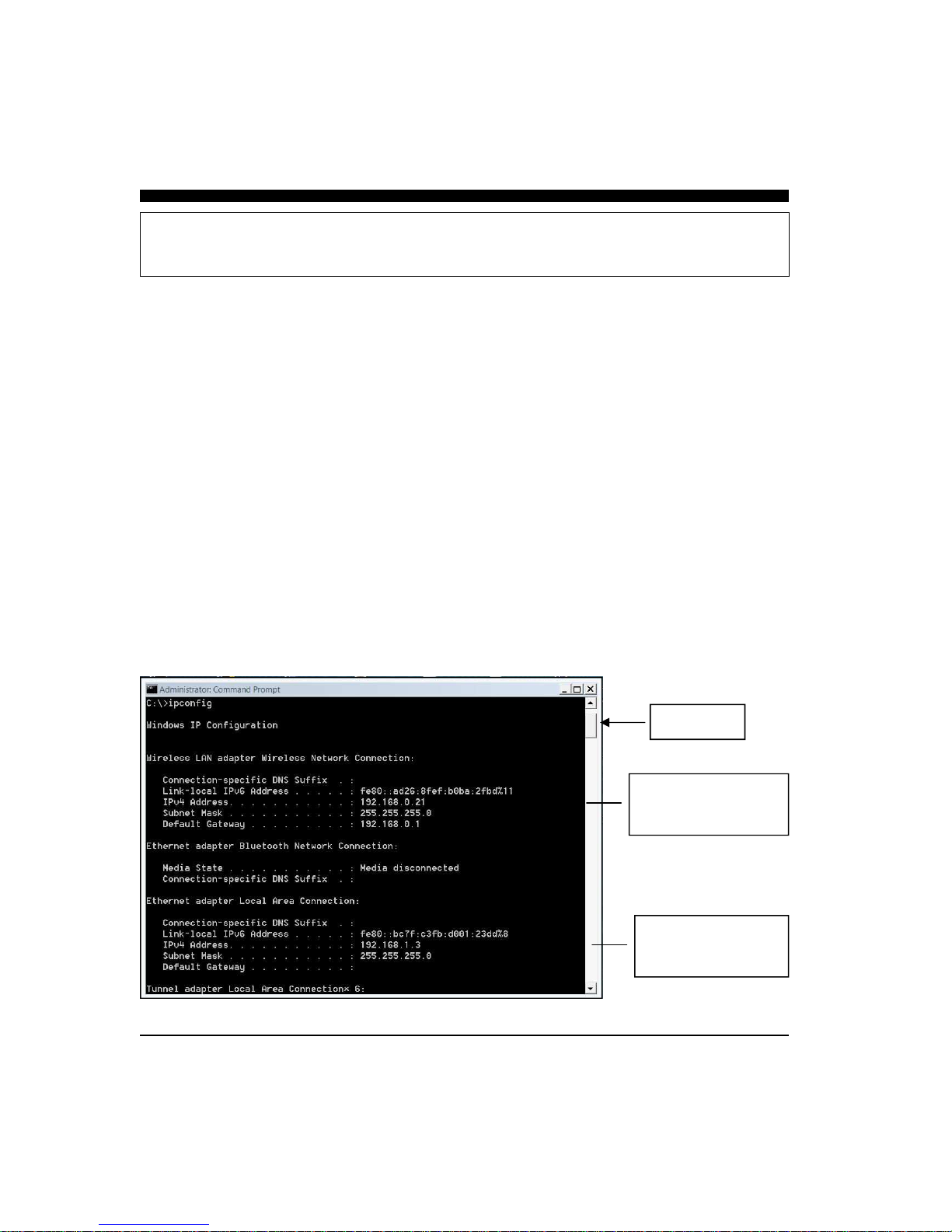
Ultrascan Network Information
The Ultrascan PC90 is designed to connect directly to a dedicated PC or to an Ethernet network.
When connected to an Ethernet network, only one PC at a time can control the Ultrascan beamformer.
This is to minimize possible conflicting commands coming from multiple computers.
For proper operation, it is important that the Ultrascan’s IP address uses the same subnet which has
been configured on the dedicated PC’s network card, or which the network is using. The subnet is the
first three blocks of digits in the IP address. For example the subnet in the IP address 192.168.1.1 is
192.168.1, and the subnet in the IP address of 192.168.0.1 is 192.168.0.
Also, the Ultrascan beamformer must have a unique device number (the last digit). For example, if
you configure your PC’s network card for IP address 192.168.1.3, the Ultrascan beamformer must
have the same subnet numbers (the first three sets of numbers –192.168.1), but it can not have the
same device number (the last group of numbers—in this case “3”).
The default IP address that is programmed into the Ultrascan beamformer prior to shipment is
192.168.1.20. In most situations when connecting to a dedicated PC, this will not have to be changed.
However, if you are connecting the Ultrascan to an existing Ethernet network you may have to reconfigure the beamformer’s IP address so that it uses the same subnet—and has a unique device number.
To find out the current IP settings of your PC, open a DOS window and type the command ipconfig
Scroll to the top of the window to see the current setting on your PC. See the example below:
Scroll Slider
Wireless Network Card’s
IP Address. Subnet is
192.168.0
Local Area Card’s
IP Address. Subnet is
192.168.1
49

Ultrascan’s Web server Page
The Ultrascan beamformer comes with a built-in web server page which can be conveniently
used to change the beamformer’s IP address, subnet mask and several other important properties.
Do not change any of these values unless required. Also, if you change the Ultrascan beamformer's IP
address—make a note of the new address. If you forget the new IP address, you will not be able to
connect to a PC or network and may have to return the red beamformer box to Interphase to reset to
the factory default IP address!
To access the Ultrascan’s web server page, connect a crossover Ethernet cable between a PC and the
Red Ultrascan beamformer . Apply power to the Ultrascan beamformer and wait 30 seconds then enter the Ultrascan beamformer’s IP address into your browser.
The default password to login and make changes is “quicksilver”. If you login, the following screen
50
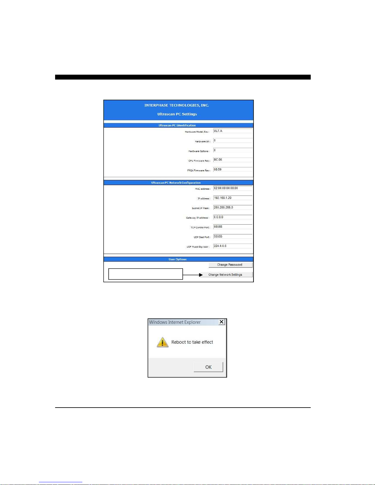
should appear in your browser:
Click here to make changes
If you make changes to any of the Ultrascan beamformer’s network settings, you will have to reboot
the beamformer by cycling power off/on.
51

Connecting to a Network
The Ultrascan Beamformer can connect directly to a dedicated PC or to an existing network by connecting the beamformer to an Ethernet hub or switch. When connecting to a network, make sure the
beamformer's IP address is set to run on the same subnet (the first three groups of numbers in the IP
address). If you’re unsure about your network’s subnet, use the ipconfig DOS command (see page
49).
When connecting to a network hub or switch a crossover Ethernet cable is usually required to connect
between the Ultrascan beamformer and the hub or switch. However, many modern network cards,
hubs and switches can use either a normal Ethernet patch cable or a crossover cable.
The beamformer’s web server page (page 50) can then be used to set the Ultrascan’s beamformer IP to
agree with the existing network settings (that is, to have the same subnet and to have a unique device
identifier). For example:
192.168.1.3
Subnet #
device #
52

This Page for Notes:
53

This Page for Notes:
54

Interphase Technologies, Inc.
Limited Warranty
Interphase Technologies, Inc. warrants this product to be free from defects
in material and workmanship for one year from the date of purchase.
Any unit that fails during the warranty period will, at Interphase’s option,
be repaired or replaced at no charge to the customer provided it is returned
to Interphase, freight prepaid with proof of date of purchase and a
description of the malfunction. Repair or replacement during the warranty
period will not extend the basic warranty period.
This warranty does not apply to an Interphase product that has failed due to
improper installation, misuse, or accident, nor does it apply to products
which have been repaired or altered outside the Interphase factory.
Any costs incurred with transducer replacement are specifically excluded
from this warranty other than the cost of the transducer itself.
This warranty does not include incidental or consequential damages and
Interphase disclaims any liability for any such damages. All implied
warranties, if any, are limited in duration to the above stated one year
warranty period. Some states and provinces do not allow the exclusion or
limitation of incidental or consequential damages, therefore, the above
limitations may not apply to you.
The completion and return of the enclosed Warranty Registration Card
is a condition precedent to the warranty coverage.
This warranty gives you specific legal rights which may vary from state to
state and province to province. This warranty is limited only to the original
purchaser of the unit.
55
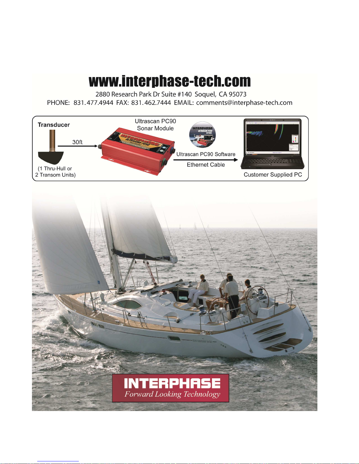
56
 Loading...