

Page 1
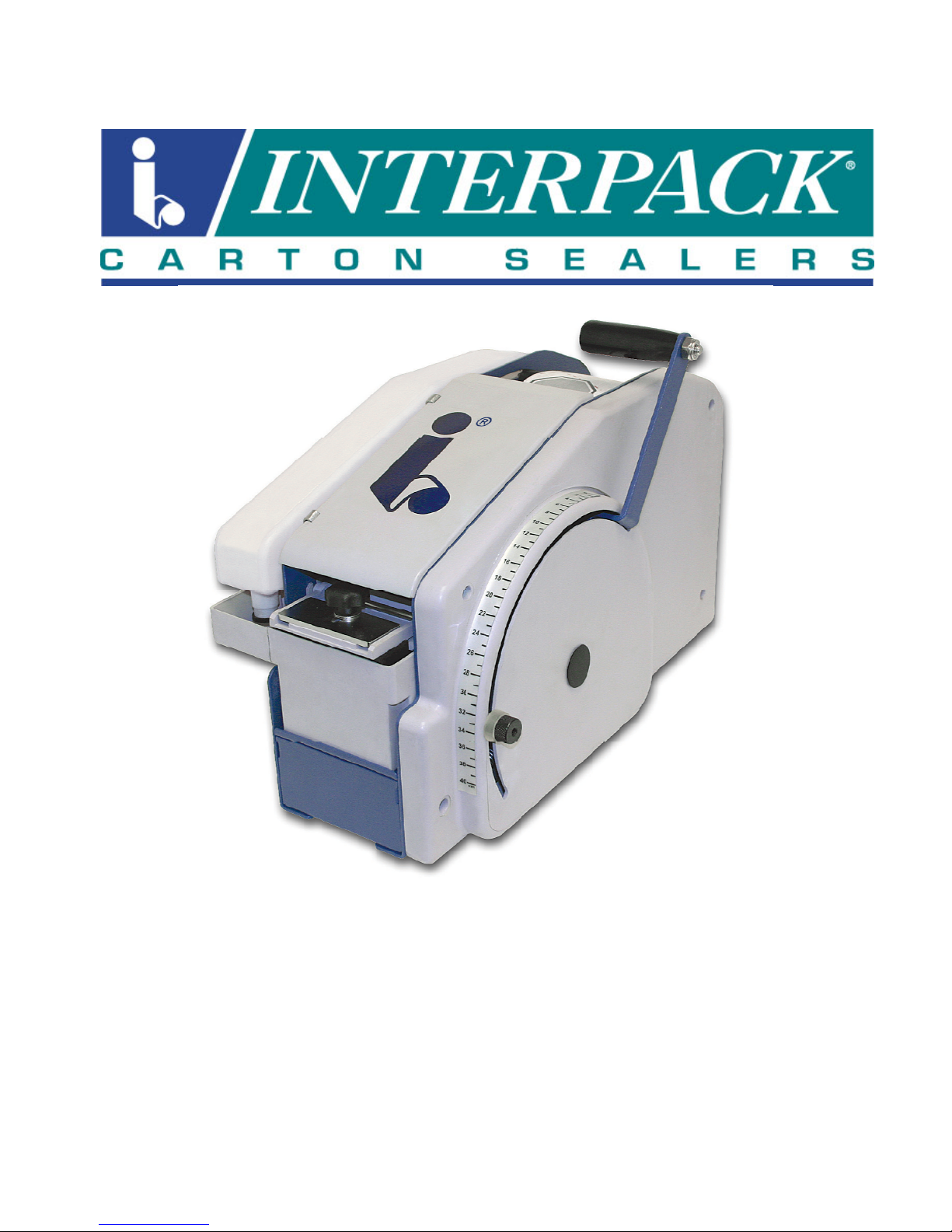
Manual Water Activated Taper
OPERATION MANUAL & PARTS LISTS
TWA 1000-M (U9701) UDM 9701
TWA 1000-M
1
Page 2

TABLE OF CONTENTS
Section 1 Table Of Contents-------------------------------------------- 2
Section 2 Technical Assistance--------------------------------------- 3
Section 3 Warranty------------------------------- -------------------------- 4
Section 4 Description Of Tape Dispenser-------------------------- 5
Section 5 Safety Issues
Section 6 Specifications
---------------------- ------- ------ ------ -------- -- 6
------------------------------------------------- 8
Water Activated Taper Dimensions--------------------------8
Water Activated Taper Components------------------------ 9
Water Activated Taper Specifications---------------------- 12
Section 7 Set Up Procedures------------------------------------------- 13
Selecting The Handle Position-------------------------------- 13
Tape Loading------------------------------------------------------- 14
Tape Threading------------------- --------------------------------- - 15
Filling The Water Bottle--------------- ------------ -------------- - 16
Removing The Brush Pot--------------------------------------- 16
Removing The Moistening Brush---------------------------- 17
Adjusting The Brush Pot Water Level---------------------- 18
Adjusting The Brush Weight----------------- ------------------ 18
Section 8 Operating Instructions---------------- ------ ------- -------- - 1 9
Adjusting The Tape Length-------------------------------------19
Dispensing Tape--------------------------------------------------- 19
Section 8 Troubleshooting---------------------------------------------- 20
Section 9 Recommended Spare Parts List------------------------- 22
Section 10 Preventive Maintenance----------------------- ------ ------- 23
Cleaning The Tape Path----------------------------------------- 23
Cleaning The Brush Pot Assembly-------------------------- 24
Cleaning The Cutter Blade----------------- ------------- -------- 2 5
Cutter Blade Maintenance-------------------------------------- 26
Cutter Blade Replacement------------------------------- ------- 27
Section 11 Appendix A-Illustrations And Parts Lists------------ 28
TWA 1000-M (U9701) UDM 9701
2
Page 3

TECHNICAL ASSISTANCE
Technical Support
This is the Interpack Model TWA 1000-M Manual Water Activated Taper you ordered. It has
been set up and tested in our factory with Intertape manufactured Water Activated tapes. If
any problems occur when setting up or operating this equipment, please contact the
authorized distributor from where you purchased this item.
Should you need to contact Interpack Technical Support, please have the Water Activated
Taper model number and serial number
nameplate of the side panel of the machine. Interpack Technical Support is available during
normal business hours (Eastern Time).
PHONE
If you have a technical question that does not require an immediate response, you may
contact Interpack by fax.
FAX
813-621-8410 x104
813-621-8473
available. This information can be found on the
Replacement Parts
Order parts by item number, part name and quantity required. Replacement parts are
only available from your Authorized Interpack Distributor exclusively.
Should you require assistance selecting the correct part, you may call:
Intertape Polymer Group
Interpack Machinery
9940 Currie Davis Drive, Suite 23B
Tampa, FL, 33619
Tel: 1-800-972-4675
Fax: 1-813-621-9680
MODEL:
SERIAL NUMBER:
DISTRIBUTOR PURCHASED FROM:
DATE OF PURCHASE:
TWA 1000-M (U9701) UDM 9701
3
Page 4

WARRANTY
EQUIPMENT WARRANTY AND LIMITED REMEDY: The following warranty is made in lieu of all other
warranties, express or implied, including, but not limited to, the implied warranty of merchantability, the
implied warranty of fitness for a particular purpose, and any implied warranty arising out of a course of
dealing, a custom or usage of trade:
Intertape sells its Interpack Tape Heads, Case Tapers and Case Erectors with the following warranties:
1. The HSD
defects for a period of ninety (90) days.
2. All other HSD
3. Water Activated Tapers’ blades and brushes will be free from defects for ninety (90) days after
delivery
4. Drive Belts will be free from defects for ninety (90) days after delivery
5. The Gear Motors will be free from defects for one (1) year after delivery.
6. All other components will be free from defects for one (1) year after delivery.
If any part is proven defective within its warranty period, then the exclusive remedy and Intertape's and
the seller's sole obligation shall be, at Intertype’s option, to repair or replace the part, provided the
defective part is returned immediately to Intertape's factory or an authorized service station designated
by Intertape.
A part will be presumed to have become defective after its warranty period unless the part is received or
Intertape is notified of the problem no later than five (5) calendar days after the warranty period.
If Intertape is unable to repair or replace the part within a reasonable time, then Intertape, at its option,
will replace the equipment or refund the purchase price. Intertape shall have no obligation to install the
repaired or replacement part.
Intertape shall have no obligation to provide or pay for the labor required to install the repaired or
replacement part. Intertape shall have no obligation to repair or replace (1) those parts failing due to:
operator misuse, carelessness, or due to any accidental cause other than equipment failure, or (2) parts
1. Failure or damage is due to misapplication, lack of proper maintenance, abuse,
improper installation or abnormal conditions such as temperature, moisture, dirt or
corrosive matter, etc.
2. Failure due to inadequate cleaning, improper operating environment, improper utilities
or operator error.
3. Failure due to operations above the rated capacities, or in any other improper manner,
either intentional or otherwise.
4. Failure is due to equipment, which has been altered by anyone other than an
authorized representative of Intertape Polymer Group.
5. Failure is due to an attempt by the purchaser to correct alleged defective equipment.
In this event the purchaser is responsible for all expenses incurred.
LIMITATION OF LIABILITY: Intertape and seller shall not be liable for direct, indirect, special, incidental or
consequential damages based upon breach of warranty, breach of contract, negligence, strict liability or
any other legal theory.
The foregoing Equipment Warranty and Limited Remedy and Limitation of Liability may be changed only
by written agreement signed by authorized officers of Intertape and seller..
2000 Tape Heads' knife blades, springs and wipe down rollers will be free from all
2000 Tape Head parts will be free from all defects for one (1) year after delivery.
TWA 1000-M (U9701) UDM 9701
4
Page 5
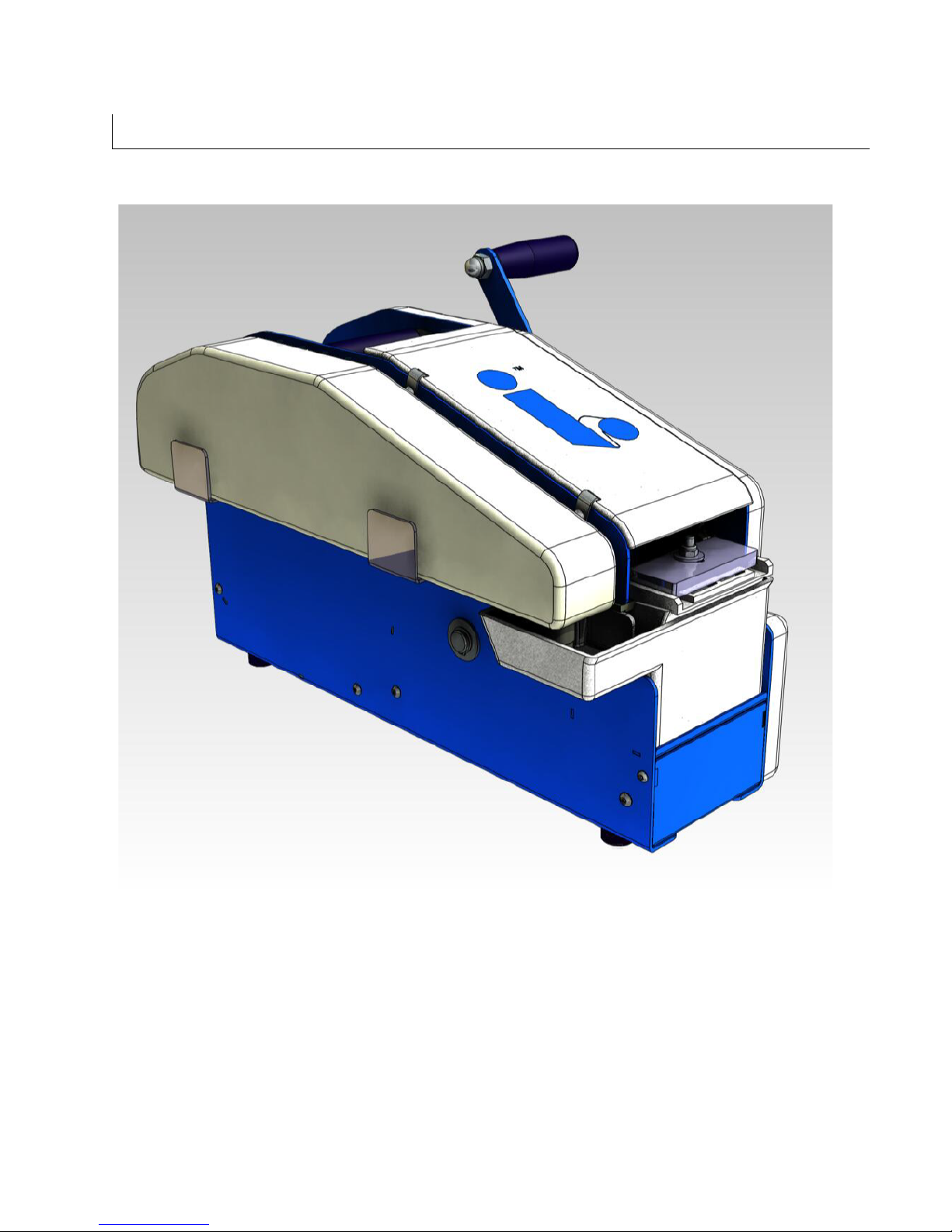
DESCRIPTION OF TWA 1000-M WATER ACTIVATED TAPER
The Interpack Family of Water Activated Tapers are designed to dispense pre-determined lengths
of pre-moistened Intertape or Central Brand water activated carton sealing tape. This tape is then
manually applied to the top and bottom center seam of regular slotted corrugated cartons.
This TWA 1000M Manual dispenses tape by engaging a pull handle.
TWA 1000-M (U9701) UDM 9701
Figure 4-1
5
Page 6

SAFETY ISSUES
There is a safety label used on all Interpack Water Activated Tapers. This label is to warn
operators and service personnel of the sharp cutting edge of the blade. Please read the label
and the following safety precautions before using the Water Activated Taper.
Read this manual for other important safety operating and service information.
Only trained personnel are to operate and service Water Activated Taper.
Wear safety glasses.
Unplug electrical power before servicing (Heater Models)
All covers and guards must be in place before operating.
Stay clear of moving parts which can shear and cut.
Note: Should any of the safety labels placed on the Water Activated
Taper be damaged or destroyed, replacements are available.
TWA 1000-M (U9701) UDM 9701
6
Page 7
SAFETY ISSUES
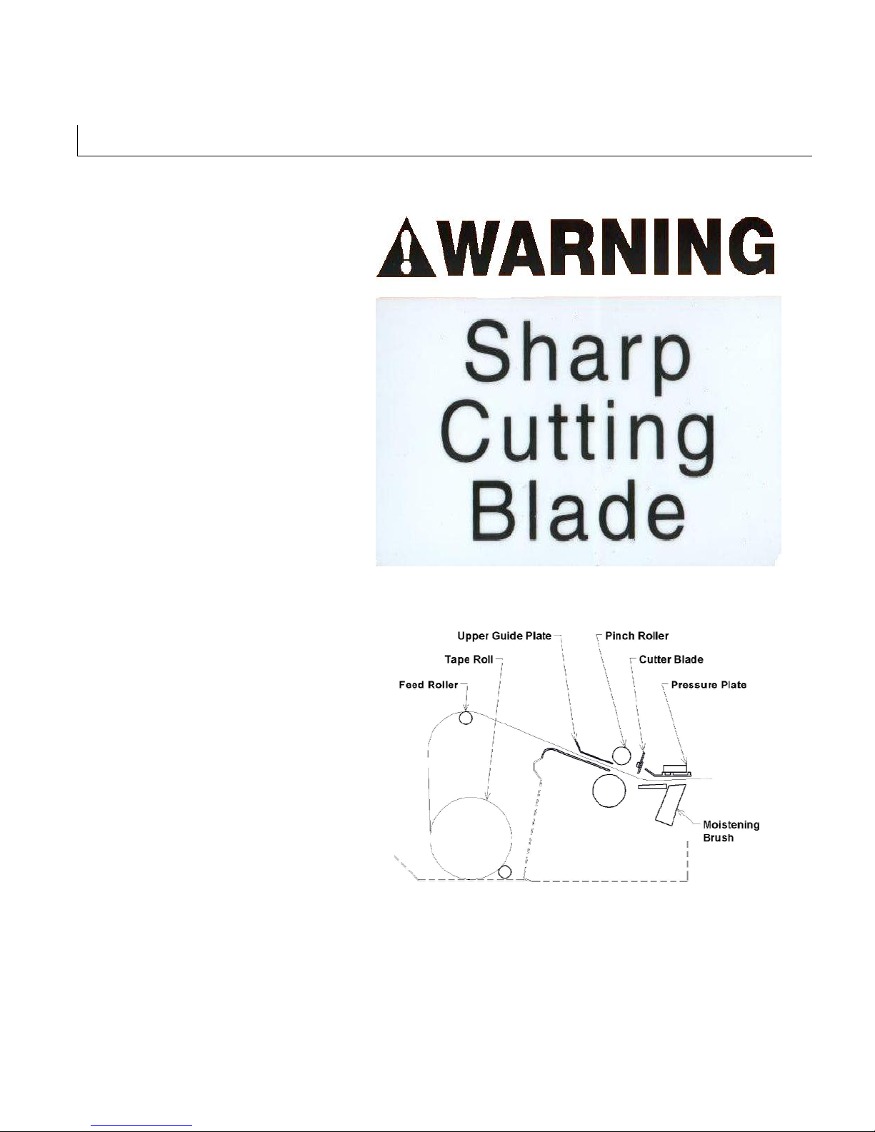
The illustrated label shown in
Figure 5-1 is attached next to the
Cutter Blade area. The label warns
operators and service personnel of
the very sharp knife used to cut the
tape at the end of the tape
application.
Turn electrical supplies off before
servicing the water activated tape
dispensers.
The illustrated label shown in Figure
5-2 is attached to the inside cover of
the water activated taper. The label
provides operators and service
personnel of the proper method of
threading a new roll of tape through
the machine.
More detailed information is provided
in the “Set Up Procedures” portion of
this manual.
Turn electrical supplies off before
servicing the water activated
taper.
Figure 5-1
Figure 5-2
TWA 1000-M (U9701) UDM 9701
7
Page 8
SPECIFICATIONS
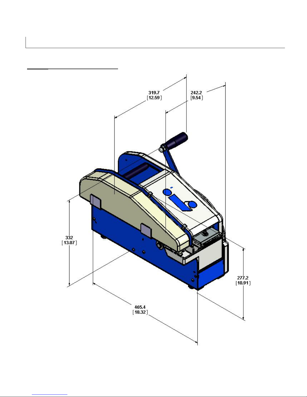
Water Activated Taper Dimensions
TWA 1000-M (U9701) UDM 9701
Figure 6-1
8
Page 9
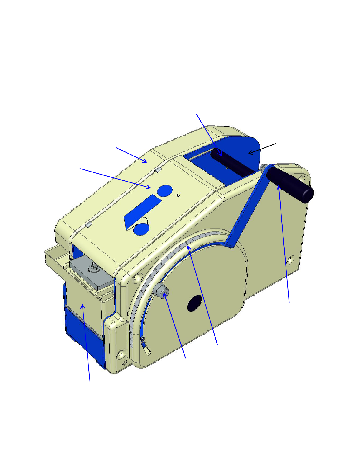
SPECIFICATIONS
Tape
Tape Length
Feed Roller
Water Bottle
Water Activated Taper Components
Hinged Cover
(Shown In Short Length
Roll Position)
Tape Roll Carriage
Brush Pot Assembly
TWA 1000-M (U9701) UDM 9701
Dispensing
Handle
Tape Length Scale
Adjustment Knob
Figure 6-2
9
Page 10
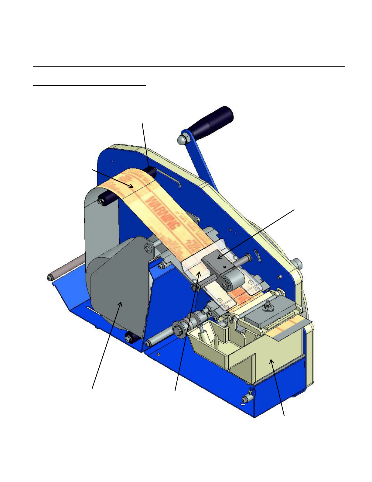
Brush Pot
Water Activated
Feed Roller
(shown in short roll
Pinch Roller
Upper
Self Centering
SPECIFICATIONS
Water Activated Taper Components
position)
Tape Roll
Side Guide
TWA 1000-M (U9701) UDM 9701
Tape Guide Plate
Assembly
Figure 6-3
10
Page 11
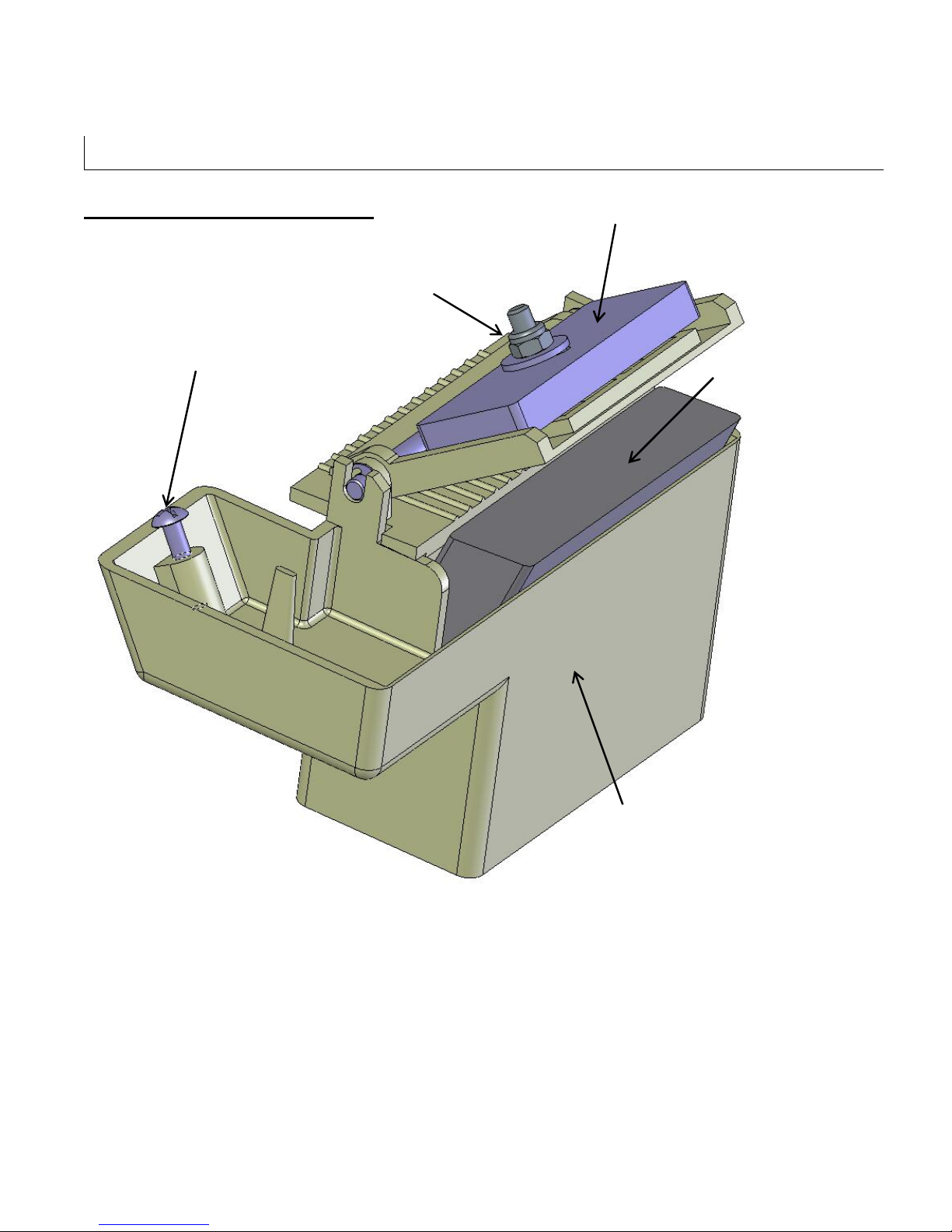
Water Level
SPECIFICATIONS
Water Activated Taper Components
Pressure Plate Lock Nut
Adjustment Screw
Pressure Plate
Moistening Brush
TWA 1000-M (U9701) UDM 9701
Brush Pot Assembly
Figure 6-4
11
Page 12

SPECIFICATIONS
Operating Conditions
Use in a dry, relatively clean environment at 40º to 105º F (5º to 40º C) with clean, dry cartons.
Note:
The TWA 1000-M should never
causing condensation on components. Do not subject the TWA 1000-M to ANY
harsh detergent or solvent wash down. The warrantee will be voided as a result.
TWA 1000-M Specifications
1) General
be washed down or subjected to conditions
Use Intertape or Central brand Water Activated Carton Sealing Tape.
2) Style
Use with 40 lb kraft or reinforced water activated tape
3) Tape Width
1” to 3 ½” (will process Central “Red Alert” and IPG “DTE” Double Tamper Evident
grades of Water Activated Tape)
4) Tape Roll Diameter
Maximum of 10 inches (254 mm) core or coreless.
(Accommodates 1000 foot (305 m) Central and Intertape roll lengths)
5) Minimum Tape Length
4 inches (101.6 mm)
6) Maximum Tape Length
42 inches (1066 mm)
NOTE: Longer tape lengths can be achieved by additional pulls of the handle prior
to releasing for cutting
7) Water Bottle Capacity
60 ounces
8) Machine Weight
30 lbs. (13.6 kg.)
TWA 1000-M (U9701) UDM 9701
12
Page 13
SET-UP PROCEDURES
Receiving and Handling
All contents must be verified upon reception. The following items are included with each tape head.
TWA 1000-M Manual Taper U9701
Operators Manual UDM 9701
Note: After unpacking the taper, look for any damage that may have occurred during
shipping. Should the Taper be damaged, file a claim with the transport company and
notify your Intertape representative.
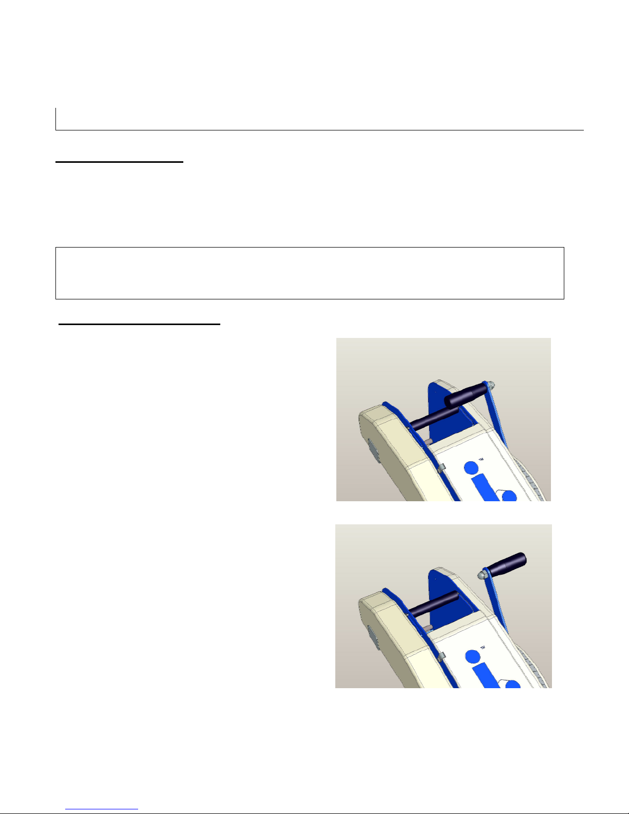
Selecting The Handle Position
The machine ships with the pull handle mounted
toward the inside of the machine
The location of the handle can be reversed should
an outside location be preferred
1. Remove the lock nut with a 17mm wrench
and a 5mm allen key
2. Reverse the handle to the position shown in
Figure 7-2
3. Reinstall the locking nut
Figure 7-1
Figure 7-2
TWA 1000-M (U9701) UDM 9701
13
Page 14
SET-UP PROCEDURES
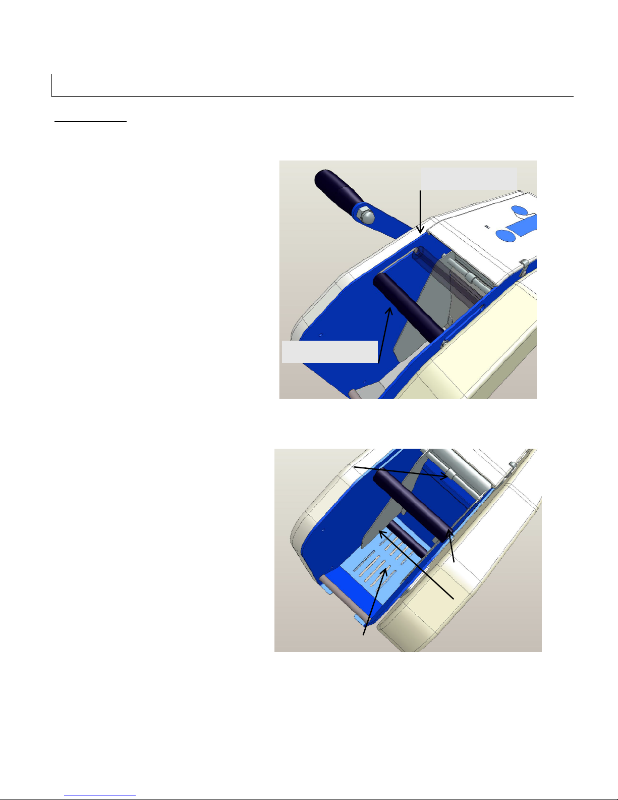
Side Guide
Feed Roller
Feed Bar Location
Feed Bar Locati
on
Tape Loading
Feed Bar Location Setting
The Feed Bar has two positions. The
location is determined by the roll length
1. Position the adjustable feed roller based
on the roll length.
2. For larger, 1000 ft. rolls, locate the feed
roller to the most forward position
3. For smaller rolls, locate the feed bar to
the farthest outboard position
For Large Tape Rolls
For Large Tape Rolls
Tape Roll Carriage
The Roll Carriage houses the tape roll and
must be set up prior to use based on the roll
width and roll length
1. Open up the self centering side guides
using the adjustment knob to permit the
insertion of the tape roll
2. Place the tape roll in the roll carriage
with the tape tab feeding toward the
discharge end of the machine
3. Adjust the width of the side guides using
the adjustment knob so that they are
about 1/8” away from the edge of the roll
and do not restrict the unwinding of the
tape.
Figure 7-3
Adjustment Knob
(shown in small roll
position)
Tape Length Scale
Tape Roll Carriage
Figure 7-4
TWA 1000-M (U9701) UDM 9701
14
Page 15
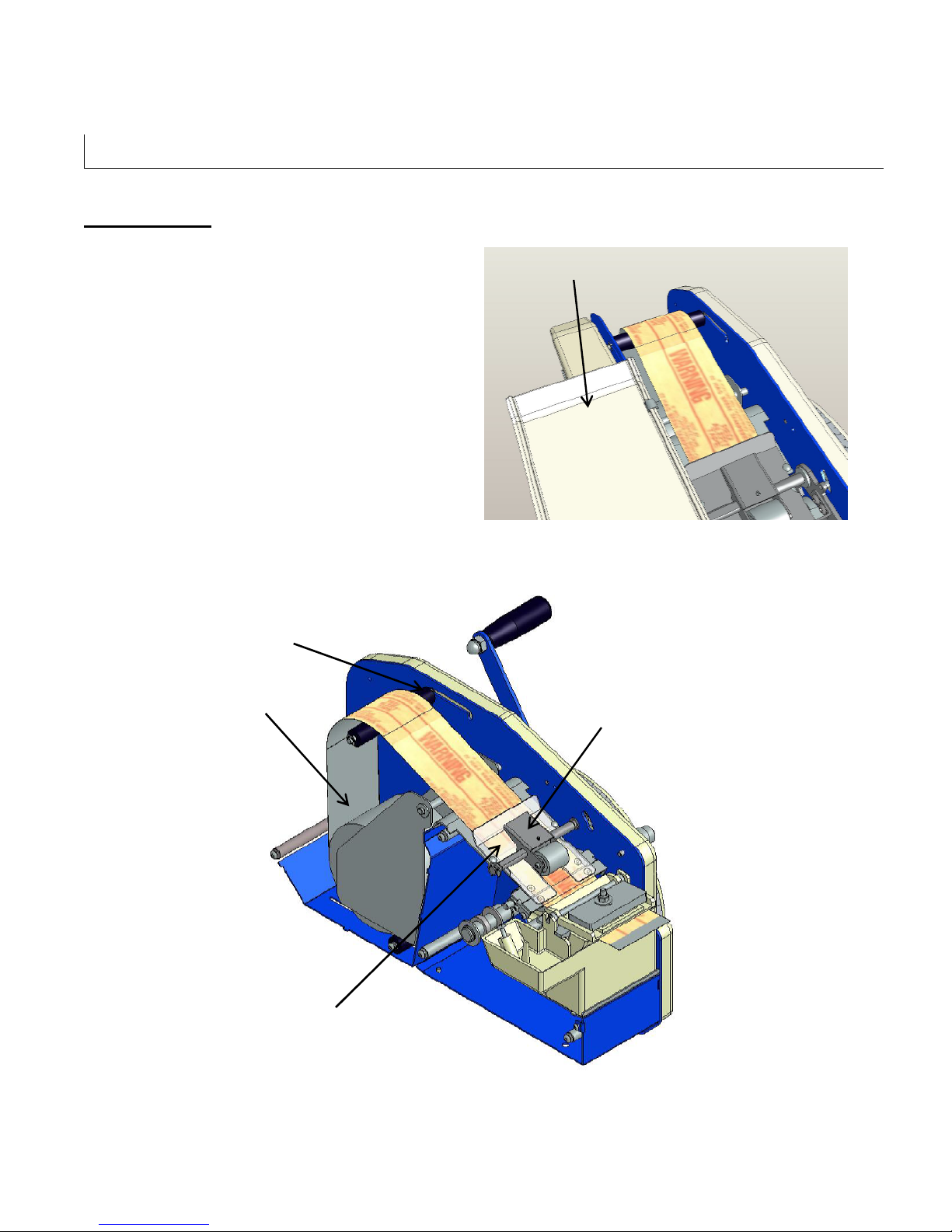
Feed Roller
SET-UP PROCEDURES
Tape Threading
1. Open the Top Cover over the threading area
2. Remove the Upper Guide Plate by
depressing the pinch roller and sliding the
plate towards the Tape Roll Carriage
3. Feed the tape leg over the feed roller and
advance under the pinch roller to just before
the knife blade
4. Reinstall the Upper Guide Plate by
depressing the pinch roller and sliding the
pressure plate on top of the tape towards the
knife arm
5. Close the top cover
(shown in small roll
position)
Tape Roll Carriage
Top Cover
Figure 7-5
Pinch Roller
Upper Guide Plate
TWA 1000-M (U9701) UDM 9701
Figure 7-6
15
Page 16
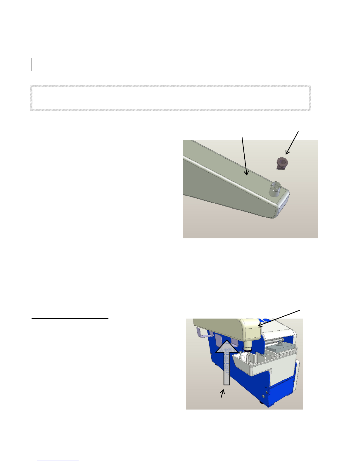
Lift Straight
SET-UP PROCEDURES
WARNING! THE KNIFE CONTAINED IN THIS WATER ACTIVATED TAPER IS EXTREMELY SHARP. USE
CAUTION WHEN THREADING THE TAPE TO AVOID PERSONNEL INJURY.
Filling the Water Bottle
Water Bottle
Rubber Valve
1. Remove the water bottle by pulling it straight
up from the brush pot. ( See Figure 7-8)
2. Turn the bottle over so the water will not spill
3. Remove the rubber valve
4. Fill the bottle with warm water
5. Replace the valve
6. Reinstall the water bottle by inserting it over
the brush pot post and into the support
brackets located on the side of the taper
Figure 7-7
Brush Pot Assembly
The brush pot contains the moistening brush and the brush weight assembly. This unit must be removed
regularly to clean the moistening brush and brush pot of any accumulated adhesive buildup. Failure to
maintain a clean moistening brush will decrease the wicking action and result in poorly moistened water
activated tape.
Removing The Brush Pot
Water Bottle
The brush pot should be removed and
cleaned regularly
1. Lift off the water bottle from the brush
pot stem as shown in Figure 7-8
2. Raise the front edge of the brush pot as
you slide it forward to remove it from the
cavity
TWA 1000-M (U9701) UDM 9701
Out
Figure 7-8
16
Page 17
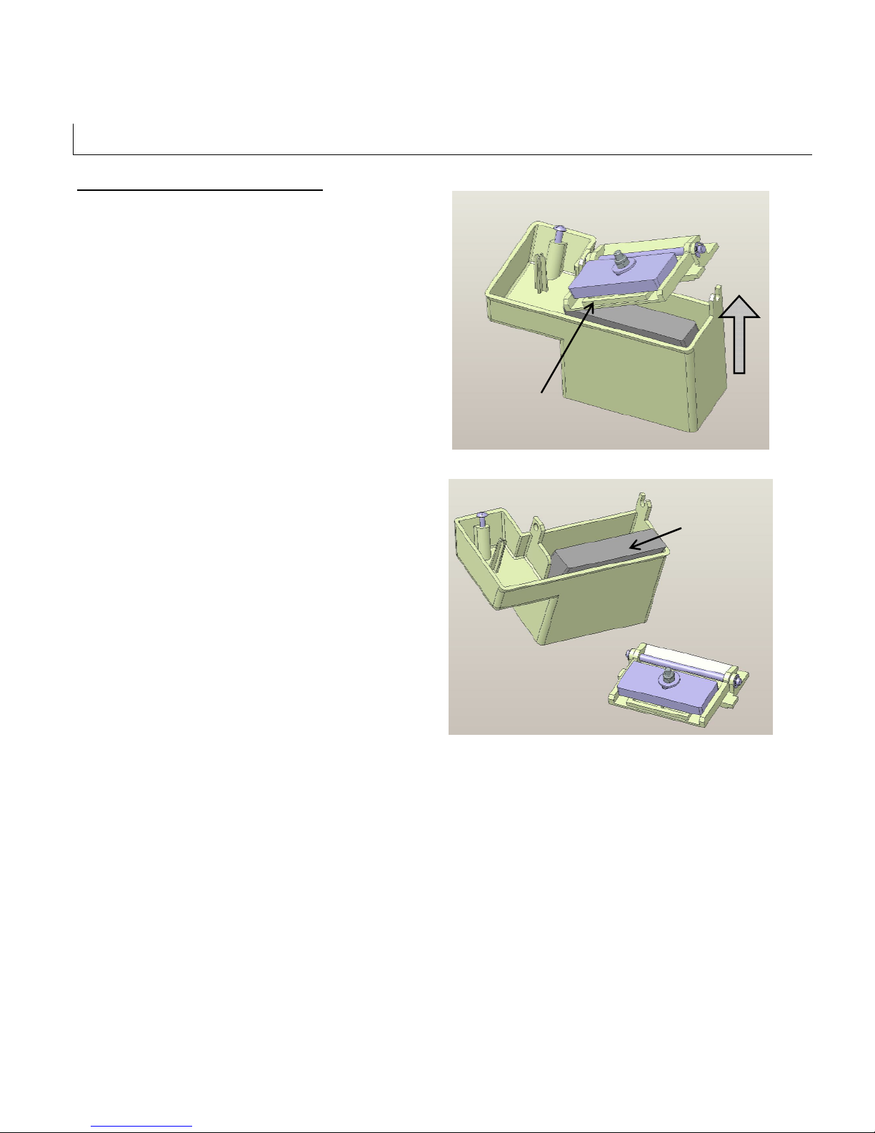
Moistening
Pressure
SET-UP PROCEDURES
Removing The Moistening Brush
1. Lift off the right side of the pressure plate
assembly.
2. Slide the pressure plate from the left side of
the brush pot
3. Pull the brush straight out from the brush
pot
4. Notice the brush angle. When replacing
the brush, insert at the same angle.
Plate
Figure 7-9
Brush
TWA 1000-M (U9701) UDM 9701
Figure 7-10
17
Page 18
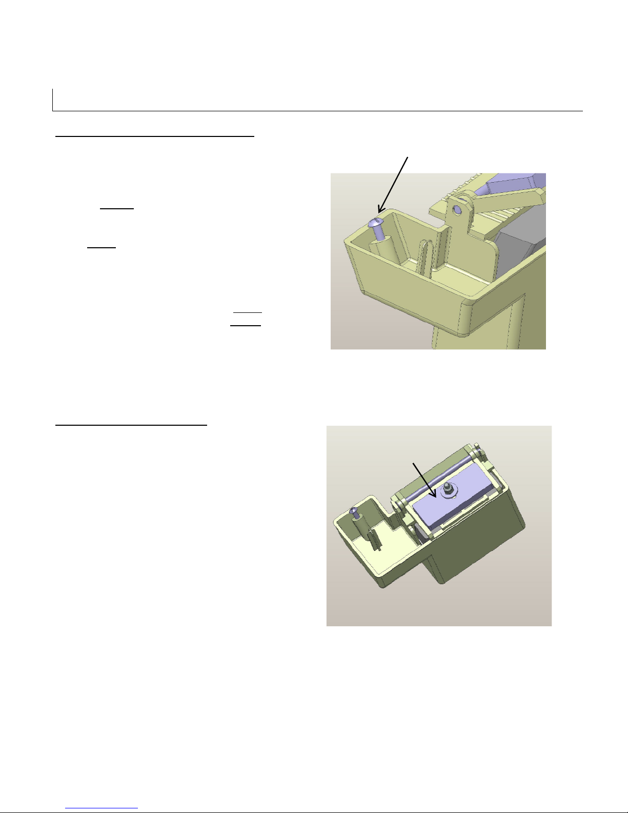
Water Level
Adjustment Screw
SET-UP PROCEDURES
Adjusting The Brush Pot Water Level
If the tape is too wet as it is processed, you may
need to Lower
If the tape is too dry as it processed, you may
need Raise
To do so:
1. Lift off the water bottle and set aside
2. Using a Phillips screwdriver, rotate the
screw counter clockwise to Raise
water level or clockwise to Lower
water level
the water level in the brush pot
water level in the brush pot.
the
the
Adjusting The Brush Weight
The function of the brush weight is to provide
enough downward pressure on the tape as it
travels over the moistening brush so that the
adhesive is properly activated. The brush
weight is adjusted at the factory and should not
require further adjustment. However, should
you process lightweight non-reinforced tapes,
you may wish to reduce the weight on the
moistening brush.
1. Loosen the locking nut
2. Slide the weight forward to increase brush
weight
3. Slide the weight to the rear to decrease the
brush weight
Figure 7-11
Brush Weight
Figure 7-12
TWA 1000-M (U9701) UDM 9701
18
Page 19
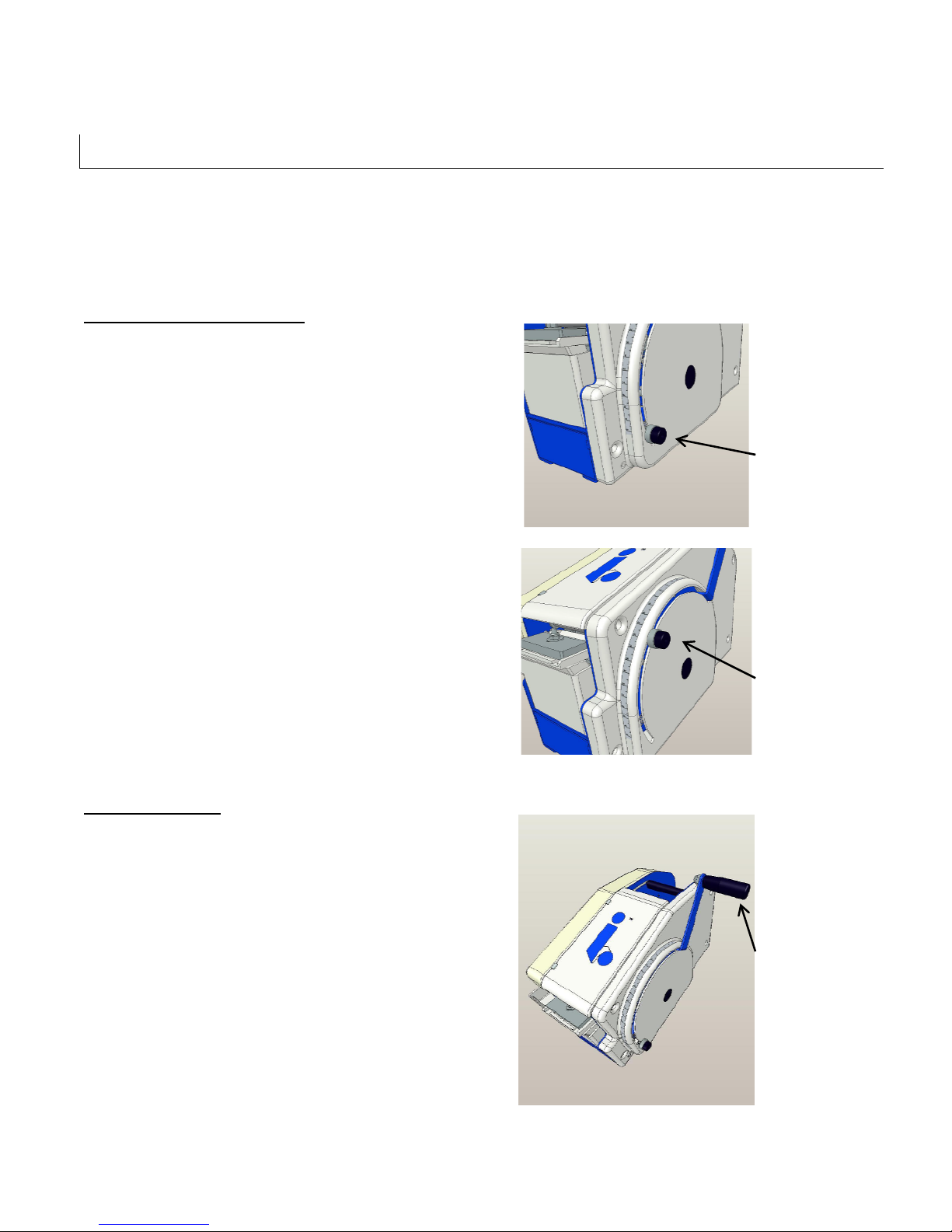
Tape Length
tape length)
Tape Length
tape length)
Tape Dispensing
position)
OPERATING INSTRUCTIONS
The TWA 1000-M should now be set up with a tape roll, properly threaded and water in the water bottle.
Operating the TWA 1000-M taper is a simple task. A quick pull of the handle will dispense fully
moistened tape ready for application to a corrugated case.
Adjusting The Tape Length
Adjustment Knob
(shown for maximum
1. Loosen the tape length adjustment
knob noted in Figure 8-1
2. Slide the knob to the desired length
Figure 8-1
3. Retighten the knob
Dispensing Tape
1. Pull the handle indicated in Figure
8-3 to the desired tape length or to
the tape length previously set
above.
2. To cut the tape, simply release the
handle
3. The handle will return to the home
position and cut the tape as it stops
Adjustment Knob
(shown for medium
Figure 8-2
Pull Handle
(shown in home
TWA 1000-M (U9701) UDM 9701
Figure 8-3
19
Page 20

TROUBLESHOOTING
The TWA 1000-M Water Activated Table Top Dispensers are fabricated with high quality components
that provide trouble-free operation for a long period of time. However, should a problem occur, we
recommend that you consult the following table. If the problem you encounter is not discussed in this
table, call Interpack Technical Support. (see page 2 of this document).
Trouble Possible Causes Solutions
Tape is jamming Debris in the tape path
Adhesive build up
Pressure plate missing or installed
incorrectly
Too much weight on the moistening
brush
Cutter blade not adjusted properly
Side guides set incorrectly
Tape does not cut
cleanly.
Tape is too dry Dirty brush
Tape is too wet Water level in brush pot too high Adjust water level in brush pot
Debris in the cutter blade
Cutter blade not adjusted properly
Blade dull
Weak Return Spring
Water level in brush pot too low
Clean Tape Path (see preventive
maintenance)
Clean tape path, moistening
brush and brush pot
Install pressure plate (see tape
threading)
Reduce brush weight setting (see
set up)
Re-adjust cutter blade (see
preventive maintenance)
Loosen or tighten as necessary
(see set up)
Clean cutter blade (see
preventive maintenance)
Re-adjust cutter blade (see
preventive maintenance)
Replace cutter blade (see
preventive maintenance)
Replace Return Spring
Clean moistening brush (see
preventive maintenance)
Adjust water level in brush pot
(see set up)
(see set up)
TWA 1000-M (U9701) UDM 9701
20
Page 21

TROUBLESHOOTING CONTINUED
Trouble Possible Causes Solutions
Tape is not evenly
moistened
Dirty moistening brush
Dirty brush pot
Clean moistening brush (see
preventive maintenance)
Clean brush pot (see preventive
maintenance)
TWA 1000-M (U9701) UDM 9701
21
Page 22

RECOMMENDED SPARE PARTS LIST
We recommend that you stock the following spare parts. These parts are contained in the spare parts
listing indicated below. The components of the spare parts kits are also referenced should individual
components need to be ordered.
TWA 1000-M Recommended Spare Parts Listing
QUANTITY NUMBER DETAIL DESCRIPTION
1 WST 1001 Cutter Blade Kit
1 WPT 0051 Cutter Blade
1 WPT 0044 Striker Plate
1 WPT 0051 Rear Block
3 UF 6351 SS FHCS M4-0,7 x 6 mm
1 WST 1002 Spring Kit
2 WPT 0008
1 WPT 0071
1 WPT 0053
1 WPT 0025 Moistening Brush
1 WPT 0032
1 WPT 0014 Duck Bill Valve
Stopper Washer
TWA 1000-M (U9701) UDM 9701
22
Page 23
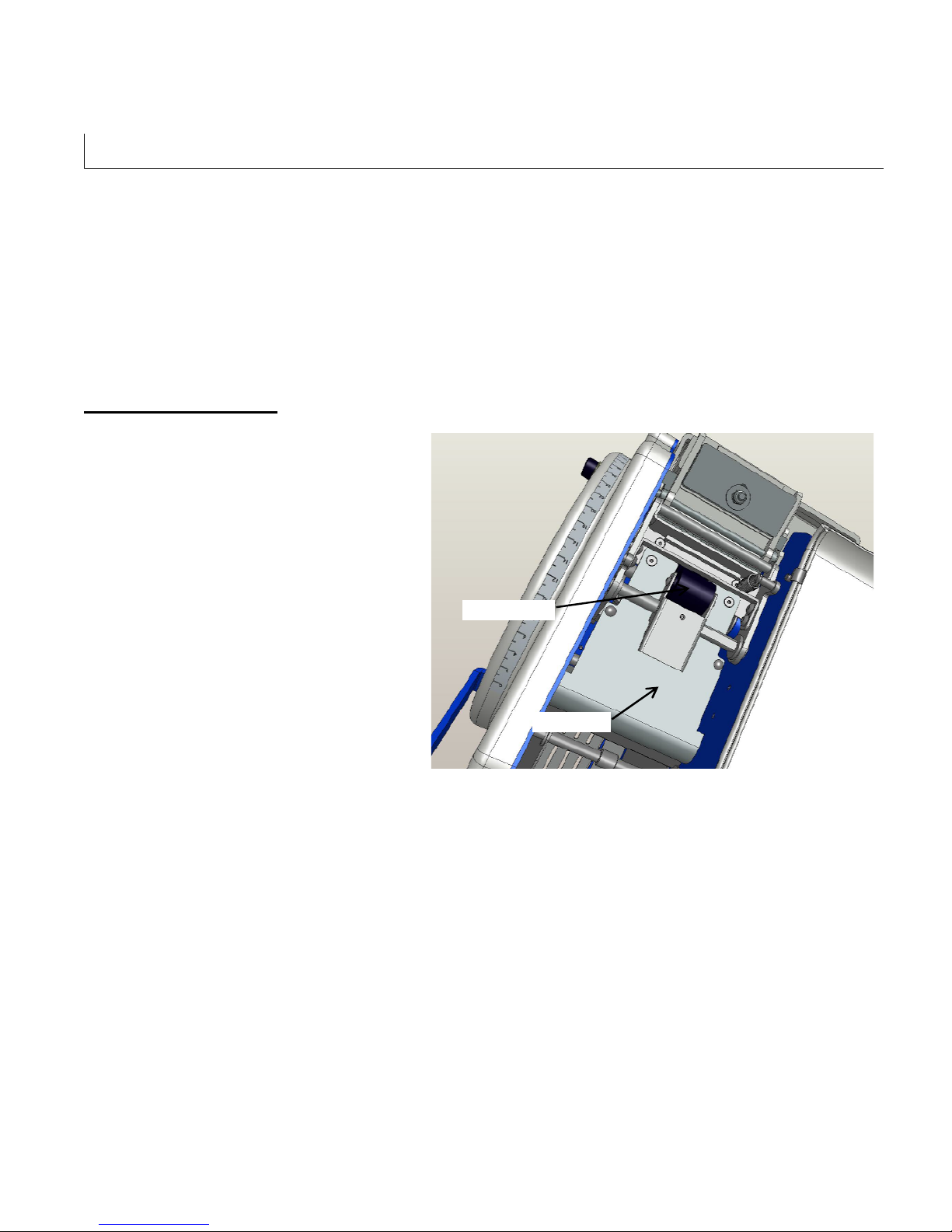
PREVENTIVE MAINTENANCE
The TWA 1000-M has been designed and manufactured with the finest components to provide long,
trouble free performance. General preventive maintenance will improve performance and prolong the life
of the water activated taper
Please review the illustration and chart below for information regarding tape head maintenance
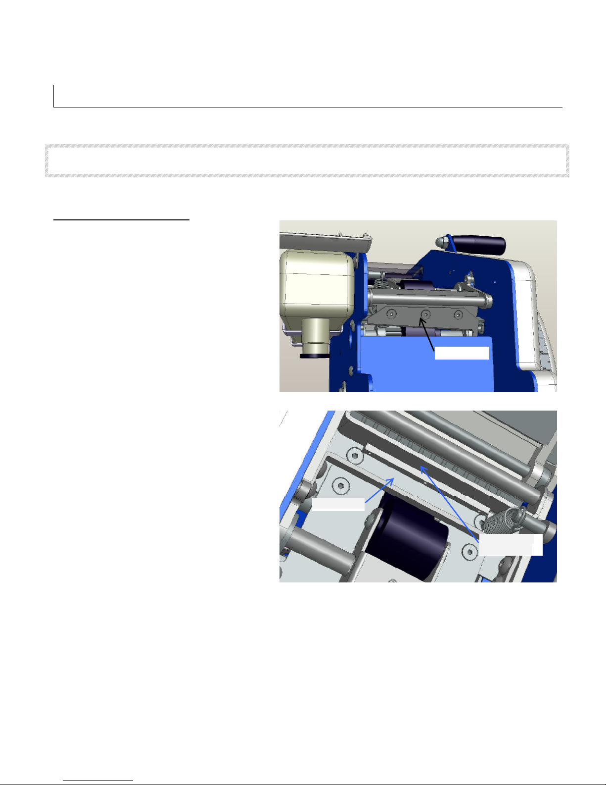
Cleaning The Tape Path
1. Remove tape from tape path
2. Remove Upper Guide plate
3. Clean pinch roller and idler roller with
warm water and mild detergent
4. Clean remaining tape path with warm
water and mild detergent
5. Clean both sides of the upper guide
plate
Pinch Roller
Guide Plate
Figure 10-1
TWA 1000-M (U9701) UDM 9701
23
Page 24
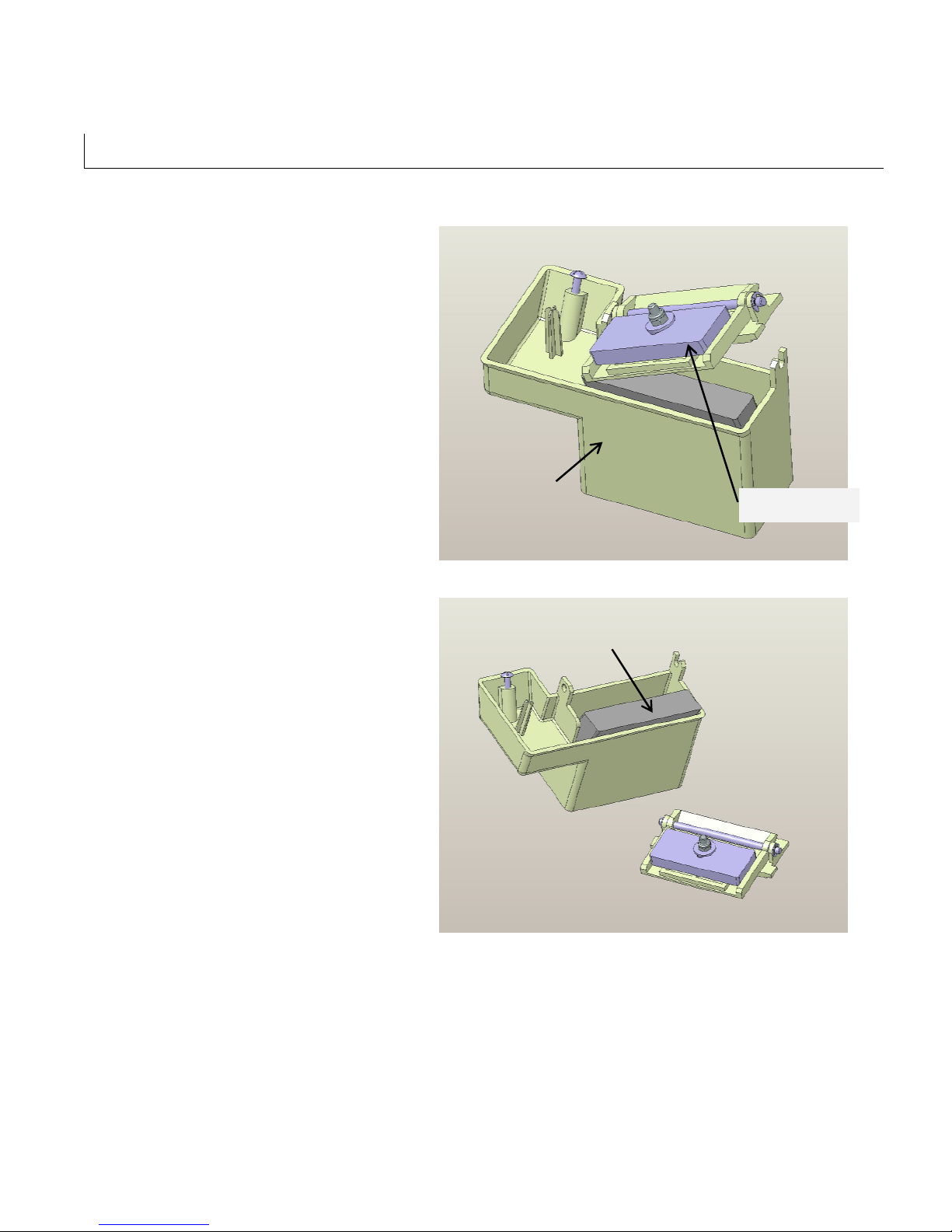
rush
Pressure Plate
Brush Pot
PREVENTIVE MAINTENANCE
Cleaning The Brush Pot Assembly
1. Remove brush pot assembly from the
machine (See Page 16)
2. Remove pressure plate assembly
3. Remove moistening brush
4. Wash moistening brush, pressure plate
and brush pot in warm water and mild
detergent
5. Reassemble and re-install in machine
Assembly
Assembly
Figure 10-2
Moistening B
TWA 1000-M (U9701) UDM 9701
Figure 10-3
24
Page 25
Back Side Of
PREVENTIVE MAINTENANCE
WARNING! THE KNIFE CONTAINED IN THIS WATER ACTIVATED TAPER IS EXTREMELY SHARP. USE
CAUTION WHEN THREADING THE TAPE TO AVOID PERSONNEL INJURY.
Cleaning The Cutter Blade
1. Remove the water bottle
2. Remove the brush pot assembly
3. Remove the upper guide plate
4. Advance the pull handle slightly to lift the
cutter blade
5. While the retaining the handle position,
clean the blade on both sides using
warm water and a mild detergent
6. Clean the striker plate using warm water
and a mild detergent
7. Replace the Upper guide plate, brush
pot assembly and water bottle
Figure 10-4
Cutter Blade
TWA 1000-M (U9701) UDM 9701
Striker Plate
Cutter Blade
Figure 10-5
25
Page 26
C
utter Blade
PREVENTIVE MAINTENANCE
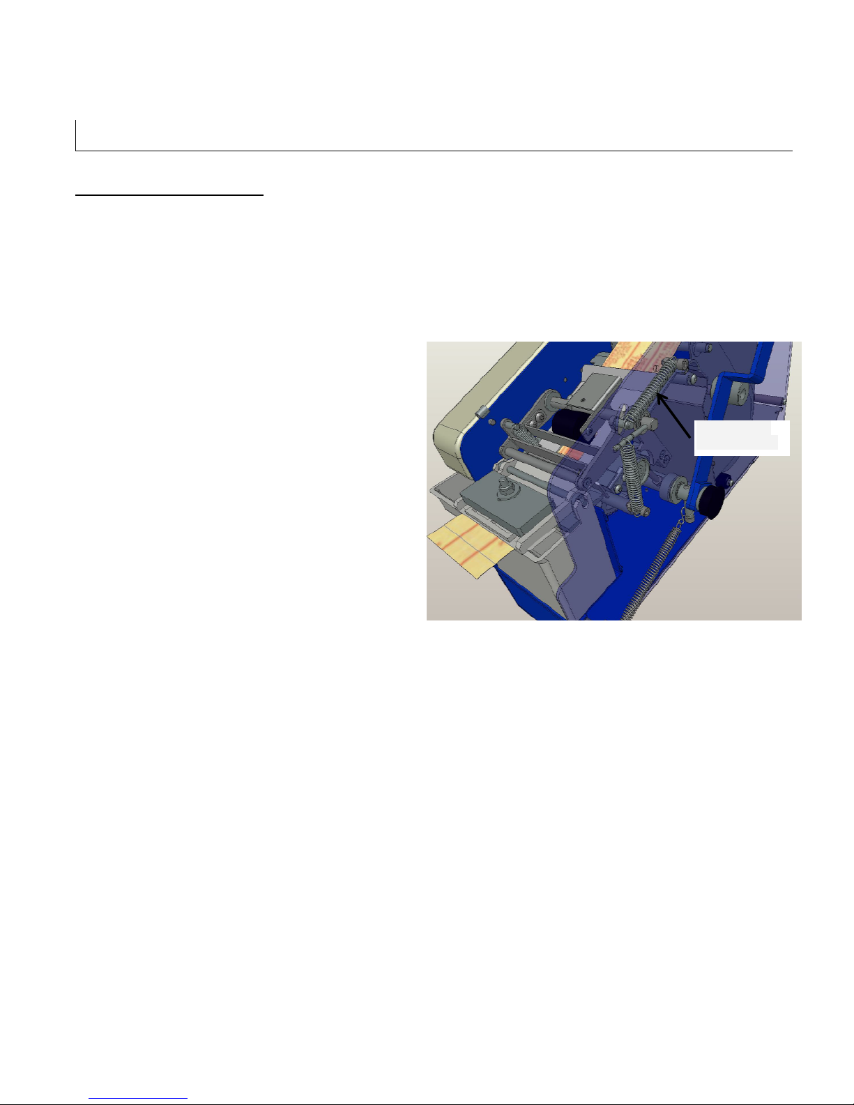
Cutter Blade Maintenance
The cutter blade must raise when the handle is
pulled to allow the tape to process underneath.
The blade must therefore raise and return
without restriction. Should the blade not raise
when the handle is pulled, check the following:
1. Remove the water bottle
2. Remove the brush pot assembly
3. Remove the upper guide plate
4. Advance the pull handle slightly to lift the
cutter blade
5. Observe to see when the blade raises that
there is no hesitation or delay.
6. Observe to see that there is sufficient
clearance between cutter blade and the tape
guide to allow the full tape width to pass
through unrestricted
7. If there is not enough clearance, remove the
right side cover.
a. Remove four 6mm screws with a 3mm
hex key
b. Remove the pull handle with a 5mm
hex key and a 17mm wrench
8. Observe the cutter blade lifting spring. When
the handle is pulled, the spring should raise
the cutter blade.
9. Replace spring if necessary
10.
Replace side cover, pull handle, upper
guide plate, brush pot assembly and
water bottle
Lifting Spring
TWA 1000-M (U9701) UDM 9701
Figure 10-6
26
Page 27
Striker
Threaded
PREVENTIVE MAINTENANCE
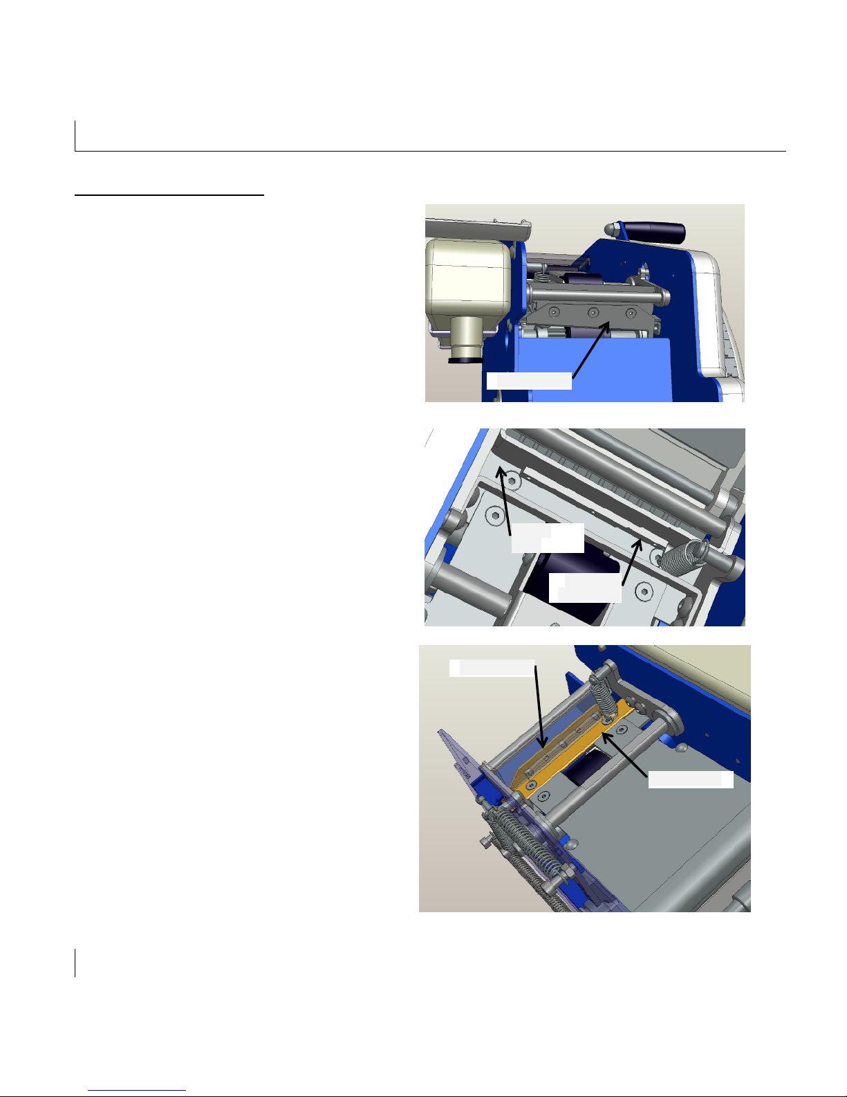
Cutter Blade Replacement
Cutter Blade
1. Remove the water bottle
2. Remove the brush pot assembly
3. Remove the upper guide plate
4. Remove the three 4mm countersink hex
screws with a 2.5 mm hex key. NOTE: Be
careful to retain the threaded back plate
behind the cutter blade as you remove the
screws.
5. Remove the cutter blade and threaded back
plate
6. Remove the two 4mm screws on the striker
plate with a 2.5mm hex key.
7. Remove the striker plate
8. Replace the cutter blade and striker plate
9. Replace the brush pot assembly, water
bottle and upper guide plate
Figure 10-7
Plate
Back Plate
Figure 10-8
Cutter Blade
Striker Plate
TWA 1000-M (U9701) UDM 9701
Figure 10-9
27
Page 28

APPENDIX A –ILLUSTRATIONS & PARTS LISTS
This page is blank
TWA 1000-M (U9701) UDM 9701
28
Page 29
29
WAT0001
3
47
21
42
25
23
31
26 27
28
32
30
36
35
33
34
38
37
39
404346 41
4
6
8
9
5
5
10
11
14
15
17
16
18
19 24
29
22
2
7
1
45
2
18
20
44
12
12
13
Page 30

30
WAT0001
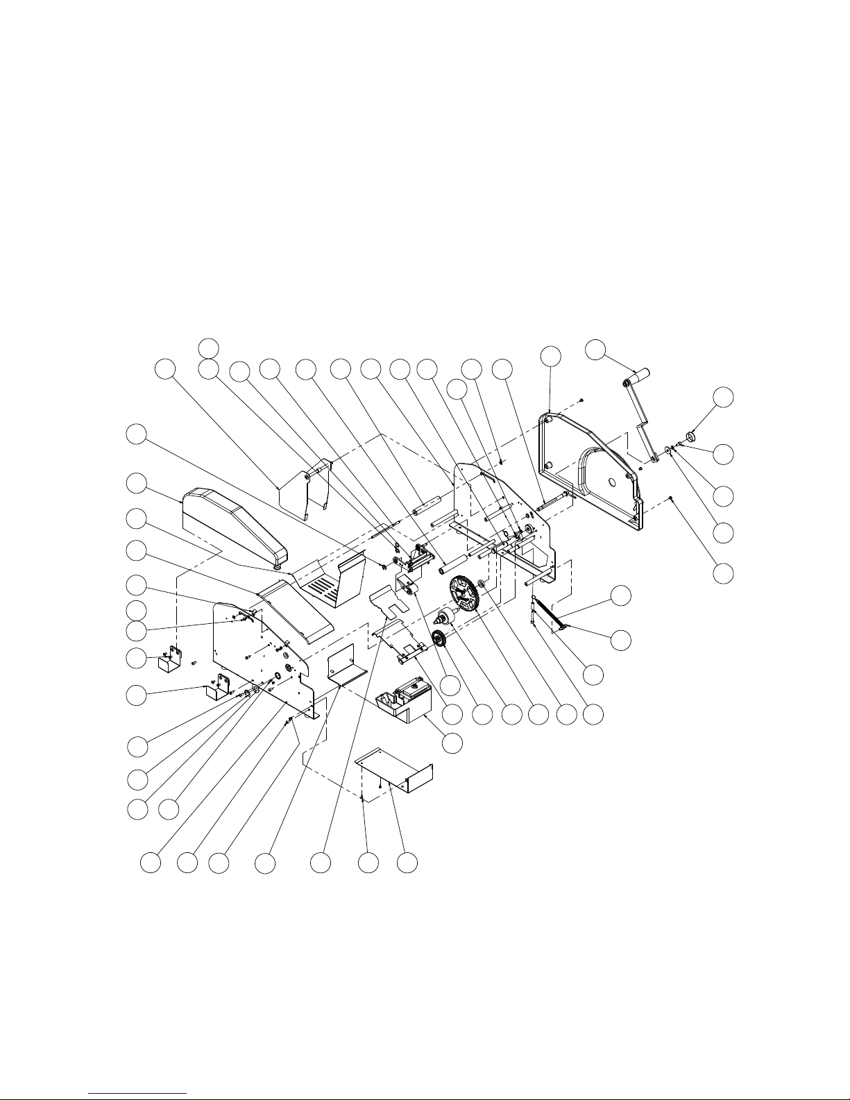
ITEM NO. PART NUMBER DESCRIPTION default/QTY.
1 WPT0058 WT Bottom Plate Front 1
2 UF7009 SS BHCS M4-0.7 x 8 4
3 WPT0063 WT Upper Guide Plate 1
4 WPT0067 WT Brush Pot Locator 1
5 UF7011 SS BHCS M5-0.8 X 12MM 6
6 WST0002 WT Frame Left Side SA 1
7 UF7008 SS BHCS M4-07 X 6MM 4
8 WPT0042 WT Washer 1
9 WPT0072 SS E-Ret'g Ring External 16mm 1
10 WPT0057 WT Bottle Locator 2
11 UF7012 SS FHCS M5-0.8 x 8 mm 4
12 UF3276 SS BHCS M5 X 0.8 X 6MM 6
13 UF 7021 SS LW5MM 2
14 WPT0056 WT Hinge 2
15 WPT0060 WT Top Cover 1
16 WPT0059 WT Bottom PlateRear 1
17 WST0003 WT Bottle SA 1
18 UF7019 SS E Ret'g ring external 10mm 3
19 WST0004 WT Self Centering SA 1
20 UF6389 NYLON F.W. 10.5 x 16 x 0.5 mm 4
21 WST0014 WT Knife Arm c/w Cutter Blade 1
22 WPT0062 WT Feed Roller Pivot Shaft 1
23 WPT0068 WT Tape Roll Roller 1
24 WPT0061 WT Feed Roller 1
25 WST0001 WT FrameRight Side SA 1
26 WST0012 WT Drive Roll Pivot SA 1
27 UF3638 SS HNR M6-1.0 2
28 UF7002 SS M6-1 X 50MM SHCS 1
29 UF7020 SS E Ret'g Ring External 6mm 2
30 WST0010 WT Drive Roll Pivot SA 1
31 WST0008 WT Cover SA 1
32 WST0005 WT Handle SA 1
33 WPT0070 WT Plastic Plug 1
34 UF3183 SS SHCS M6-1 X 12mm 1
35 UF6341 SS LW6MM 1
36 WPT0069 WT Washer 1
37 WPT0071 WT Ext'n Spring c/w Hook 1
38 UF3180 SS M6-1 X 25MM SHCS 1
39 WPT0064 WT Stopper 1
40 UF7001 SS M6-1 X 40MM SHCS 1
41 WPT0065 WT Spacer 1
42 WST0006 WT One Way Gear SA 1
43 WST0011 WT Drive Roll SA 1
44 WPT0066 WT Double Gear 1
45 WST0007 WT Brush Pot SA 1
46 WST0013 WT Tape GuideSA 1
47 WST0009 WT Pinch Roller SA 1
Page 31
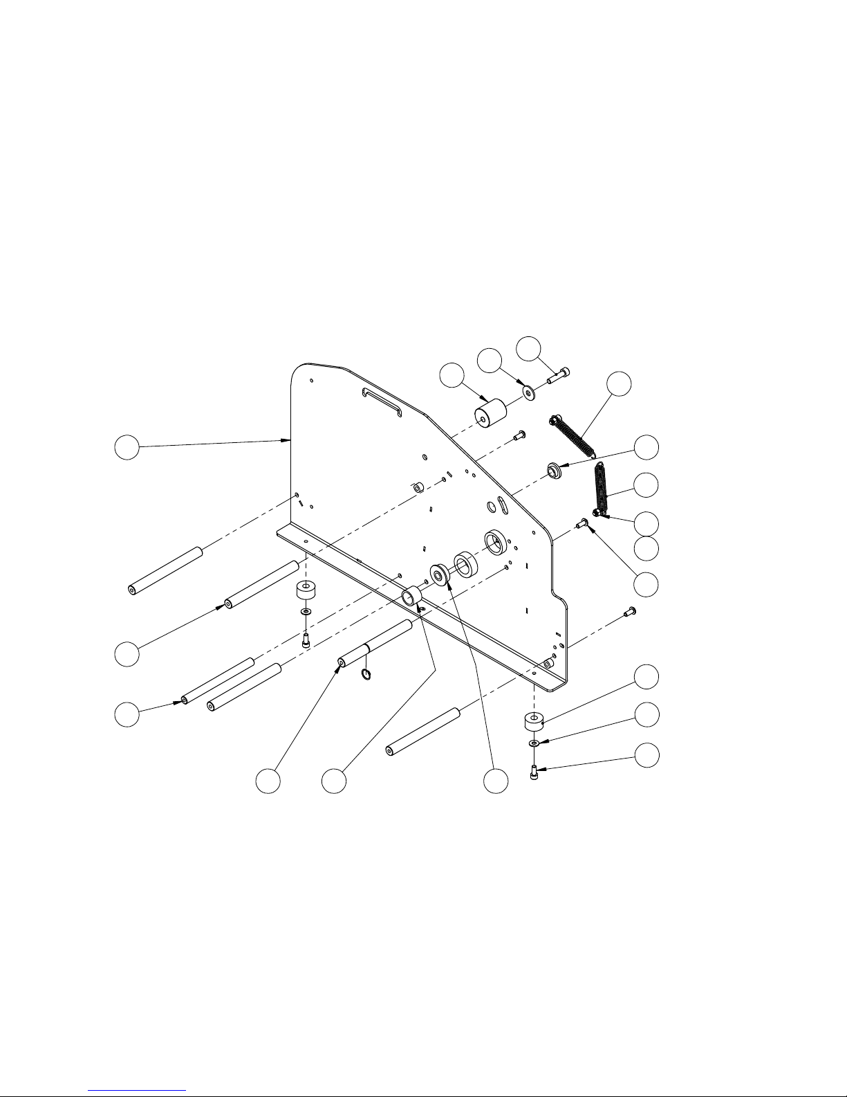
31
WST0001
1
6
15
3
13
24
5
16
9
8
7
14
11
17
18
12
10
Page 32

32
WST0001
ITEM NO. PART NUM BER DESCRIPTION
Default/
QTY.
1 WPT0001 WT Frame Right Side 1
2 WPT0002 Flange Bearing 8mm 1
3 WPT0004 OilliteFlange Bearing 10mm 1
4 WPT0003 Oillite Bearing 16mm 1
5 WPT0005 WT Foot 2
6 WPT0006 WT Bumper 1
7 WPT0007 WT Spacer Bar 4
8 WPT0009 WT Roller Shaft 1
9 WPT0010 WT D ouble Gear Shaft 1
10 UF3147 SS SHCS M5 X 0.8 X 10MM 2
11 UF7003 SS SHCS M5 - 0.8 x 12 2
12 UF7007 SS HEX NUT M5-0.8 2
13 UF7011 SS BHCS M5-0.8 X 12MM 6
14 WPT0008 WT SPR ING 1
15 WPT0008 WT SPR ING 1
16 UF6340 SS FW 5 mm 2
17 UF6341 SS FW 6 mm 1
18 UF3180 SS M6-1 X 25MM SHCS 1
19 UF7017 SS Ret'g Ring External 12mm 1
Page 33
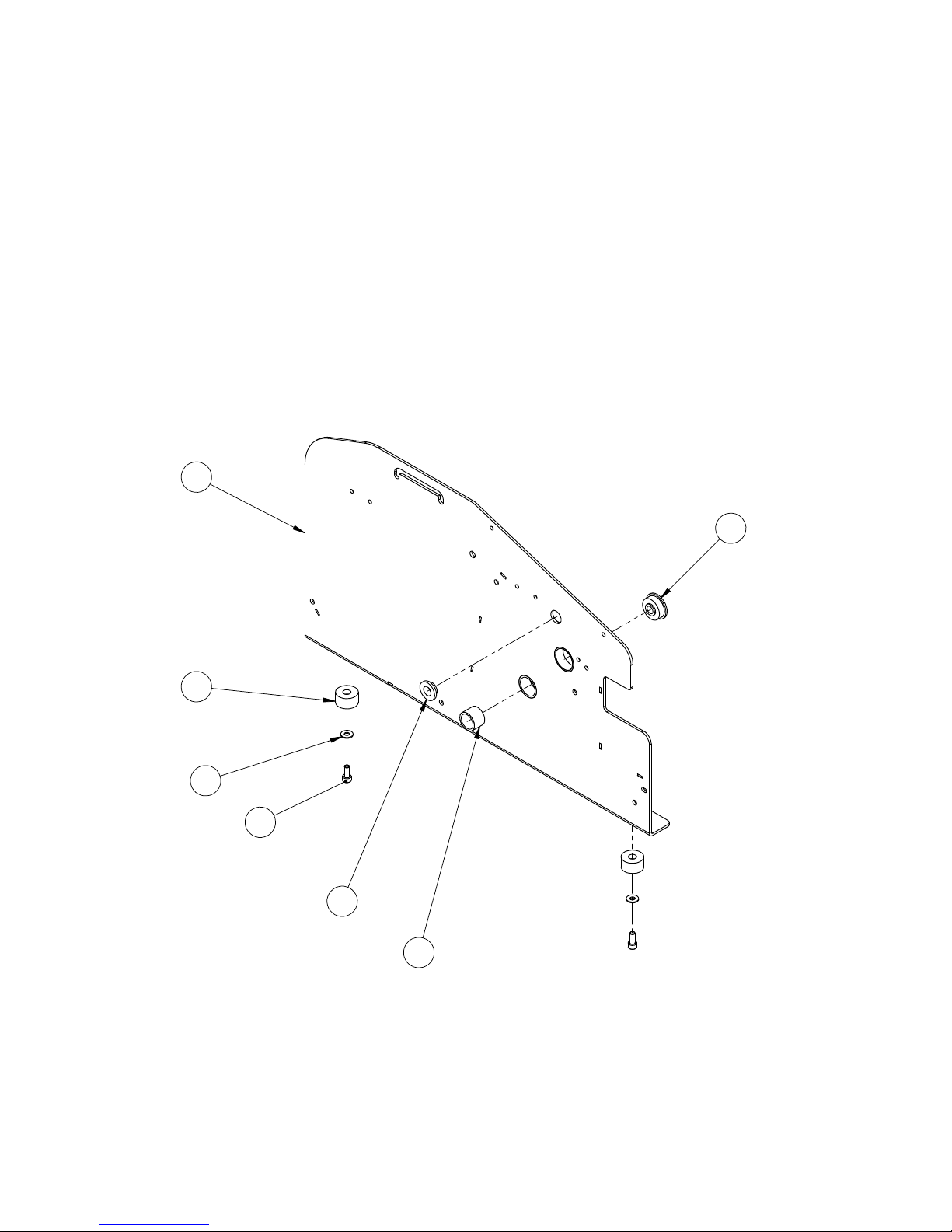
33
WST0002
1
4
2
6
3
5
7
Page 34

34
ITEM NO. PART NUMBER DESCRIPTION QTY.
1 WPT0012 WT Frame Left Side 1
2 WPT0002 Flange Bearing 8mm 1
3 WPT0003 Oillite Bearing 16mm 1
4 WPT0004 OilliteFlange Bearing 10mm 1
5 WPT0005 WT Foot 2
6 UF6340 SS FW 5 mm 2
7 UF7003 SS SHCS M5 - 0.8 x 12 2
WST0002
Page 35
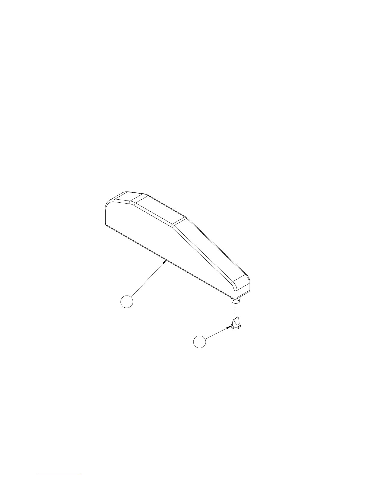
35
2
1
WST0003
Page 36

36
WST0003
ITEM NO. PART NUMBER DESCRIPTION QTY.
1 WPT0013 WT Bottle 1
2 WPT0014 WT Duck Bill Valve 1
Page 37
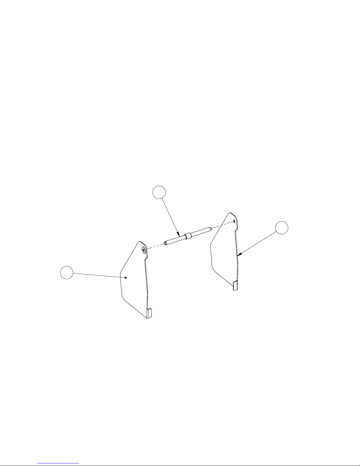
37
3
1
2
WST0004
Page 38

38
WST0004
ITEM NO. PART NUMBER DESCRIPTION QTY.
1 WPT0015 WT Double Threaded Screw 1
2 WPT0016 WT Self Centering Right Side Guide 1
3 WPT0017 WT Self Centering Left Side Guide 1
Page 39
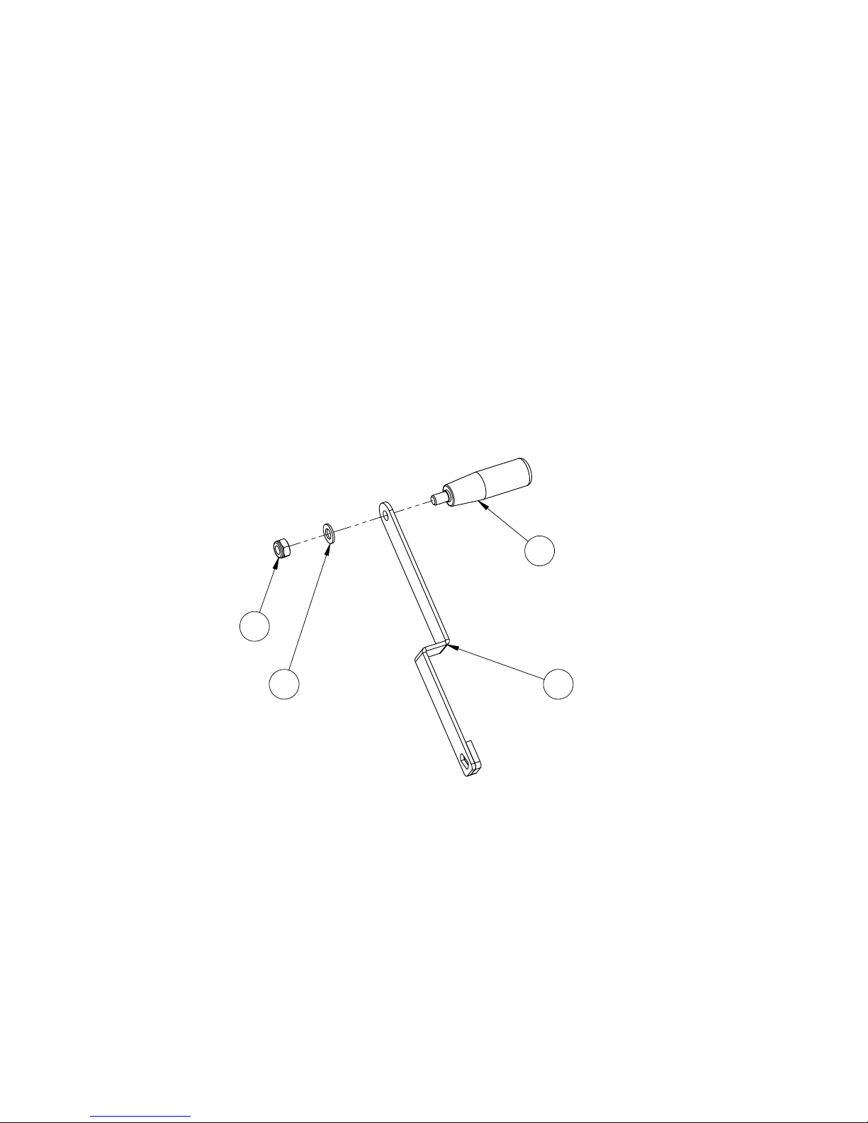
39
2
1
3
4
WST0005
Page 40

40
ITEM NO. PART NUMBER DESCRIPTION QTY
1 WPT0018 WT Arm 1
2 WPT0019 WT Handle 1
3 UF7014 SS M10-1.5 N Nylon Lock Nut 1
4 UF7015 SS FW M10 1
WST0005
Page 41
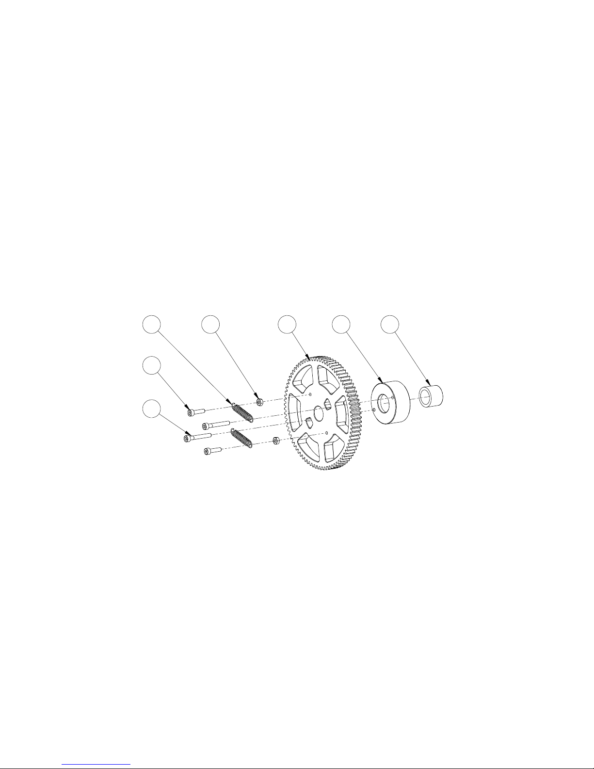
41
4 1 2 3
6
5
7
WST0006
Page 42

42
ITEM NO. PART NUMBER DESCRIPTION QTY.
1 WPT0020 Gear 80t, 120mm dia 1
2 WPT0021 Bearing Housing 1
3 WPT0022 One way bearing 1
4 WPT0023 WT Spring 2
5 UF7005 SS SHCS M4-0.7 X 16MM 2
6 UF7004 SS SHCS M4-0.7 X 30MM 2
7 UF7006 SS HEX NUT M4-07 2
WST0006
Page 43
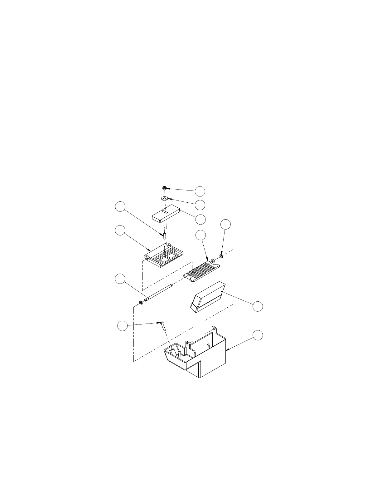
43
11
6
1
10
3
5
8
9
4
2
7
WST0007
Page 44

44
ITEM NO. PART NUMBER DESCRIPTION QTY.
1 WPT0024 Wt Water Pot 1
2 WPT0027 Wt Pivot Shaft 1
3 WPT0026 Wt Tape Guide 1
4 WPT0028 Wt Pressure Plate 1
5 WPT0029 Wt Weight 1
6 WPT0025 Wt Moistening Brush 1
7 UF7016 SS Thrd Rod M6-1 X 20mm Lg 1
8 UF6341 SS FW 6 mm 1
9 UF3391 SS M6 LOCKNUT 1
10 UF7020 SS E Ret'g Ring External 6mm 2
11 UF7000 SS PHS M5 X 25MM 1
WST0007
Page 45
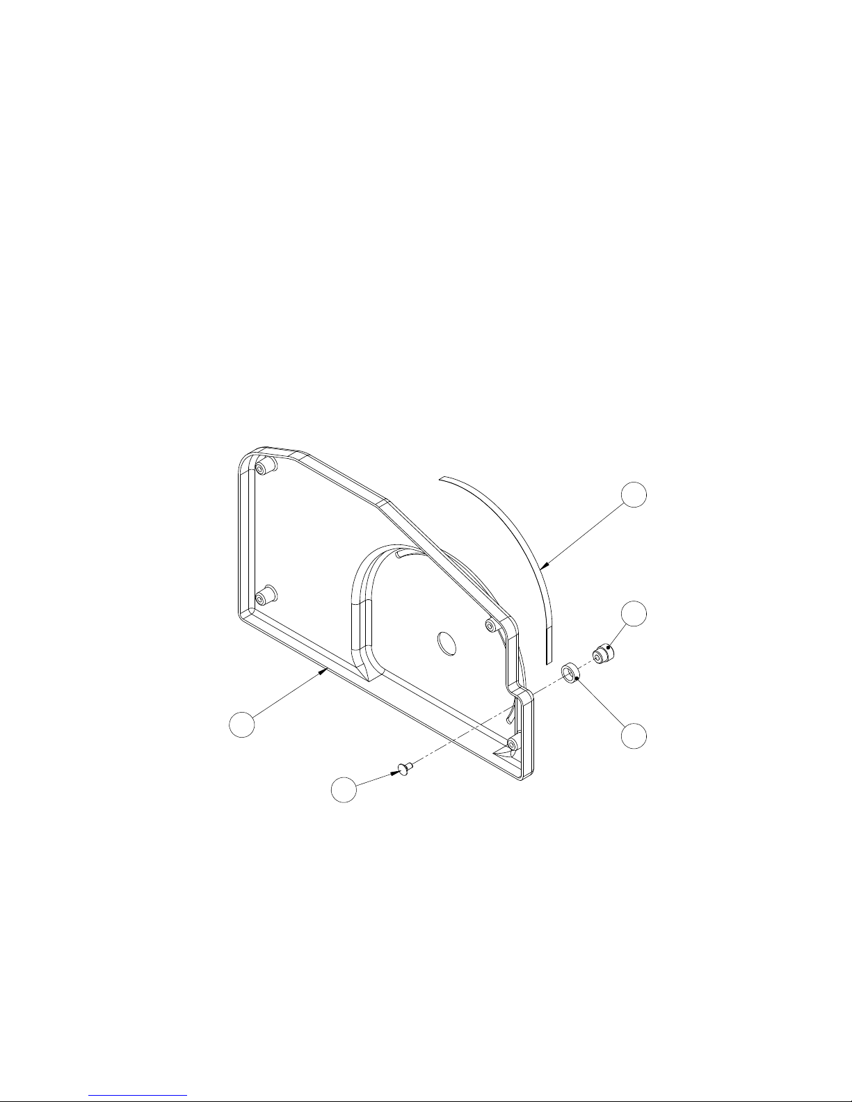
45
1
3
2
4
5
WST0008
Page 46

46
ITEM NO. PART NUMBER DESCRIPTION QTY.
1 WPT0030 WT Cover 1
2 WPT0031 WT Knurled Nut 1
3 WPT0032 WT Stopper Washer 1
4 WPT0011 WT Scale 1
5 UF4009 CARRIAGE BOLT HK 1/4-20 X 1/2 1
WST0008
Page 47
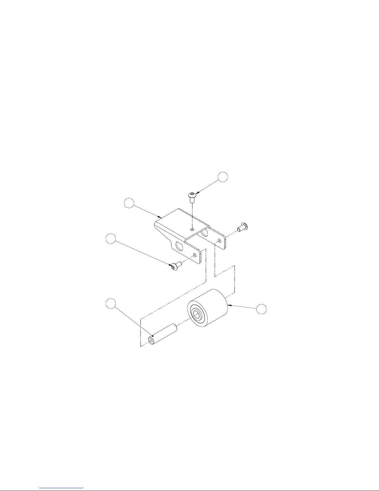
47
WST0009
1
3
4
2
4
Page 48

48
ITEM NO. PART NUMBER DESCRIPTION QTY.
1 WPT0033 WT Pinch Roller Support 1
2 WPT0034 WT Pinch Roller 1
3 WPT0035 WT Pinch Roller Shaft 1
4 UF7009 SS BHCS M4-0.7 x 8 3
WST0009
Page 49
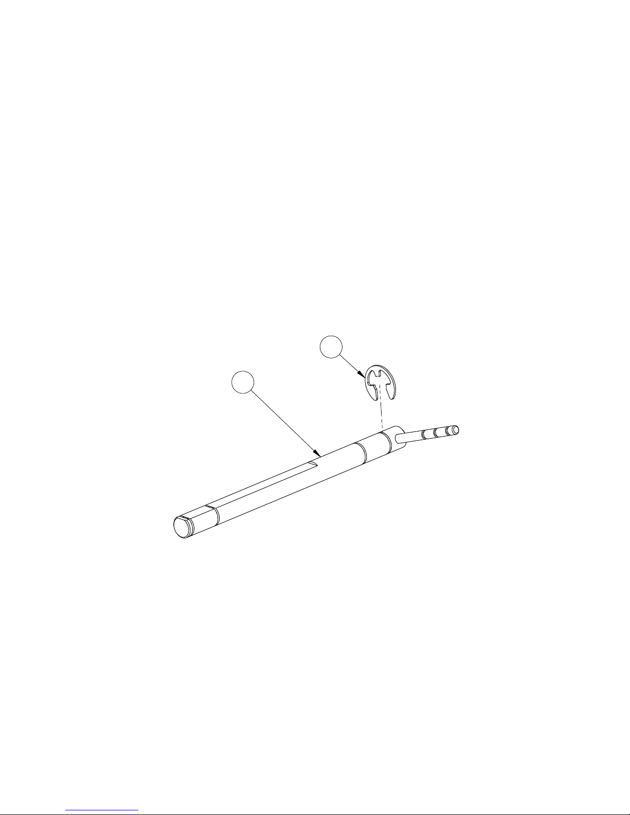
49
2
1
WST0010
Page 50

50
ITEM NO. PART NUMBER DESCRIPTION QTY.
1 WPT0036 WT Drive Roll Pivot Shaft 1
2 UF7019 SS E Ret'g ring external 10mm 1
WST0010
Page 51
51
4
3
2
1
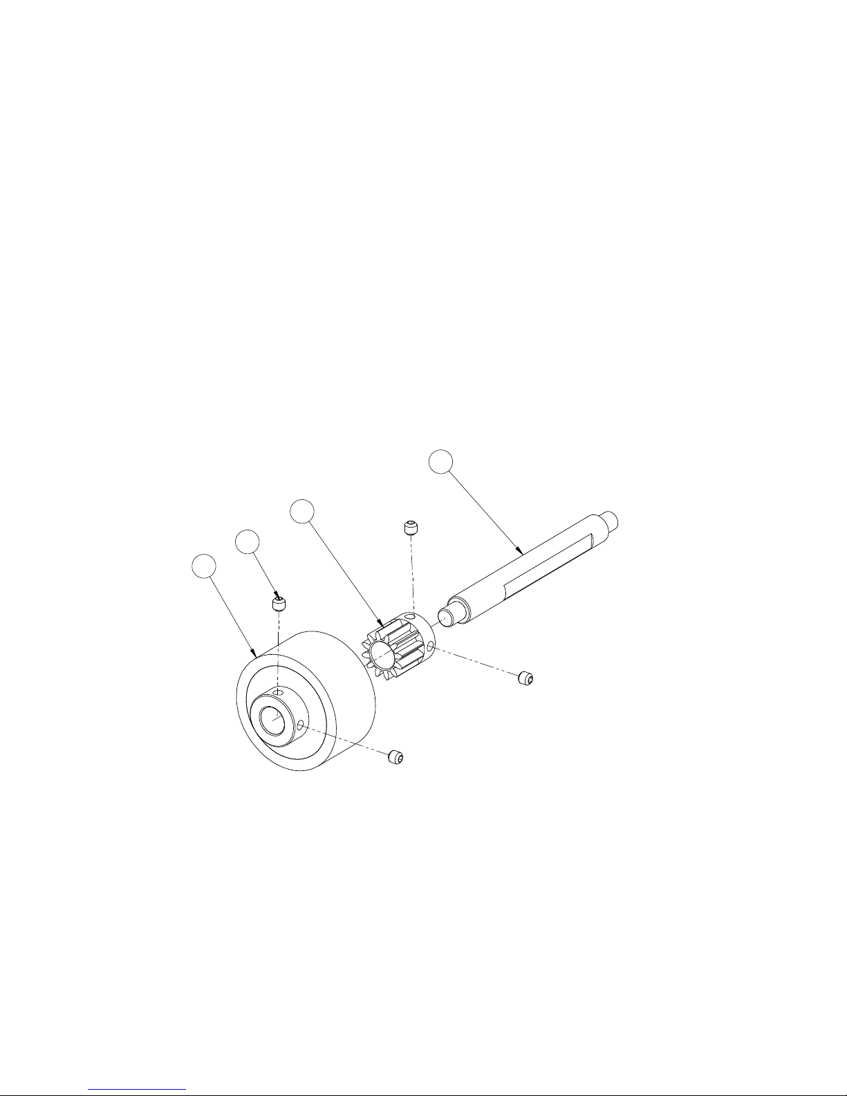
WST0011
Page 52

52
ITEM NO. PART NUMBER DESCRIPTION QTY.
1 WPT0040 WT Drive Roll Shaft 1
2 WPT0038 WT Drive Roll 1
3 WPT0039 WT Drive Roll Gear 1
4 UF7013 SS SSS M5 X 5MM 4
WST0011
Page 53
53
1
2
4
3
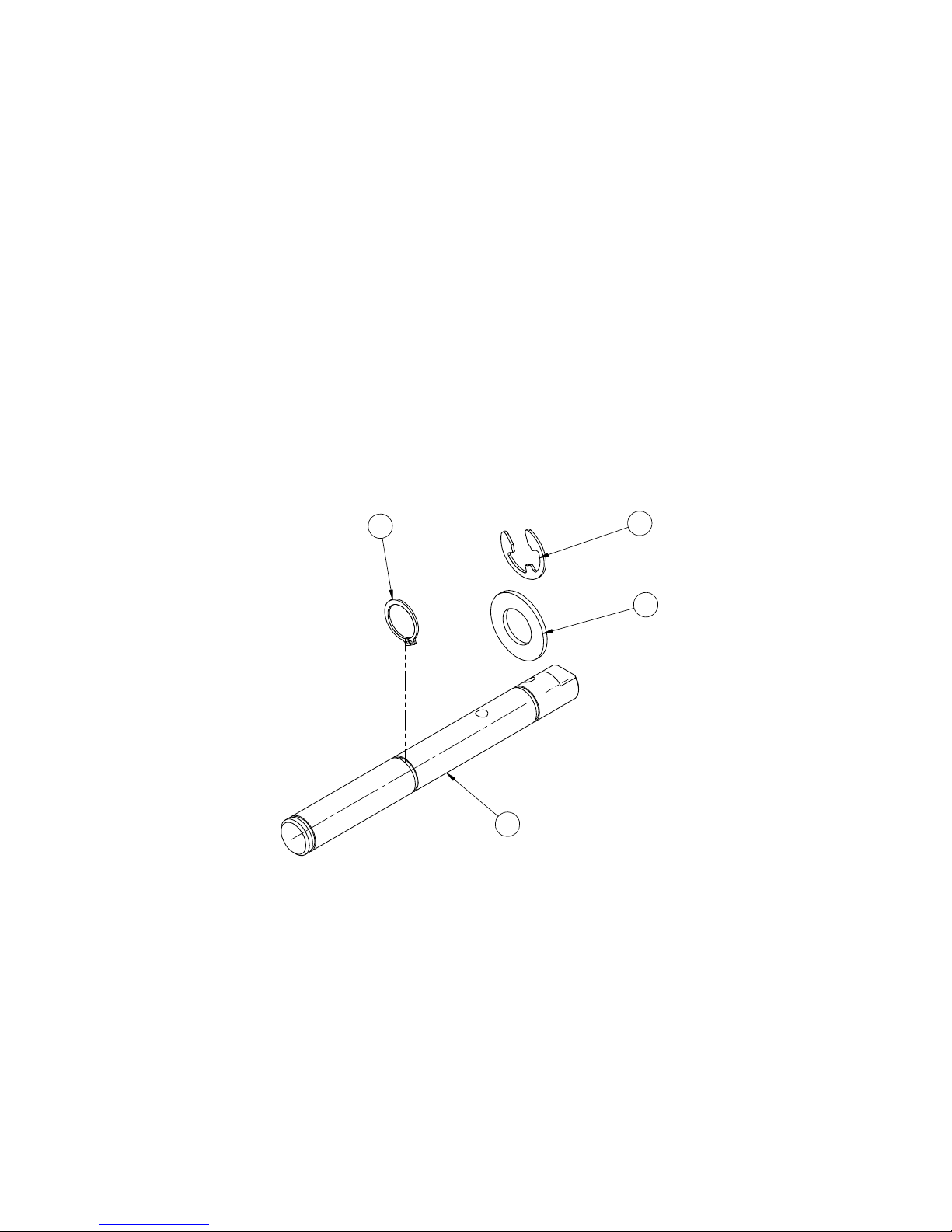
WST0012
Page 54

54
ITEM NO. PART NUMBER DESCRIPTION QTY.
1 WPT0041 WT Drive Roll Pivot Shaft 1
2 WPT0042 WT Washer 1
3 WPT0072 SS E-Ret'g Ring External 16mm 1
4 WPT0073 SS Ret'g Ring External 16mm 1
WST0012
Page 55
55
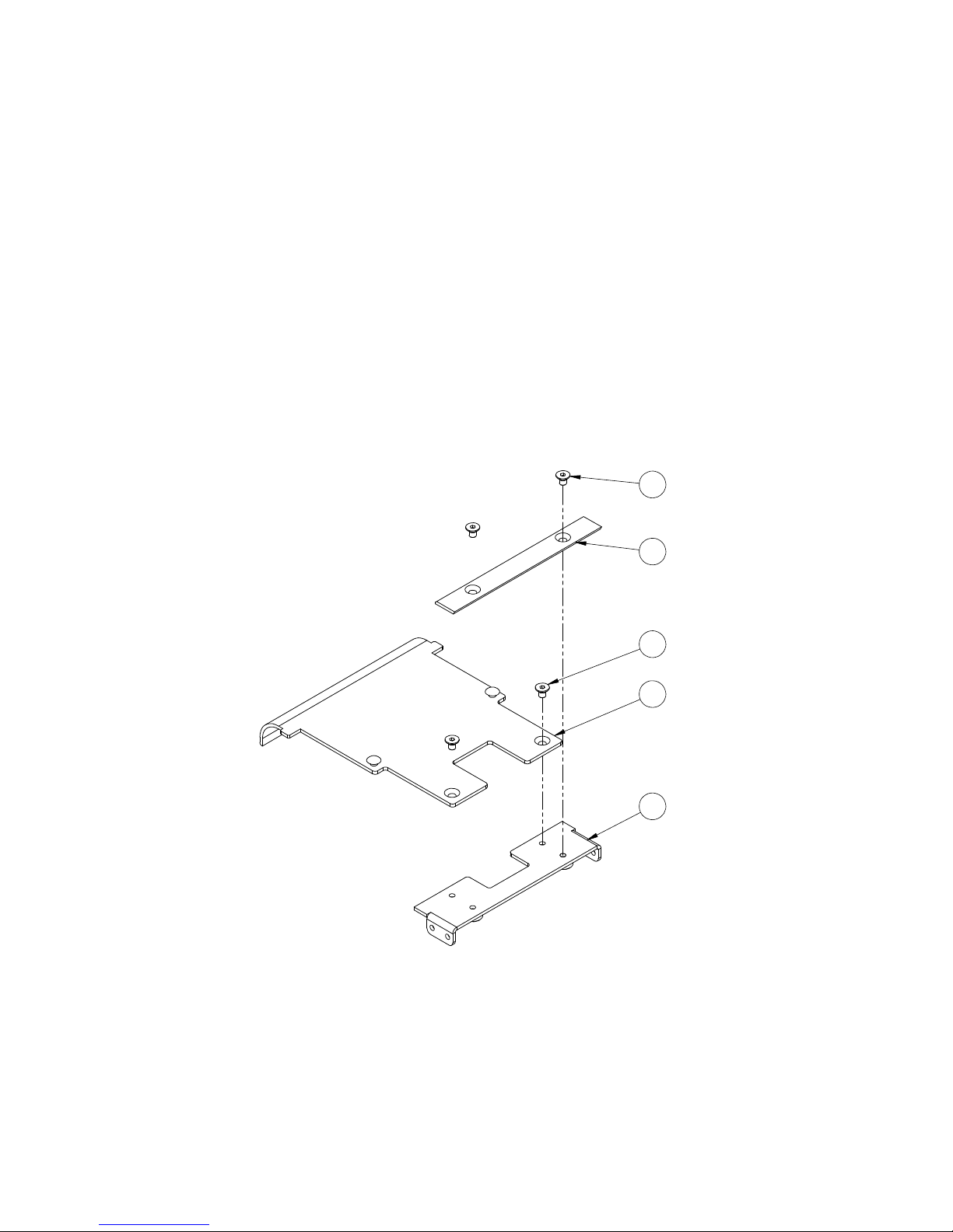
WST0013
3
2
4
1
4
Page 56

56
ITEM NO. PART NUMBER DESCRIPTION QTY.
1 WPT0043 WT Tape Guide Support 1
2 WPT0045 WT Tape Guide 1
3 WPT0044 WT Stricker Plate 1
4 UF6351 SS FHCS M4-0.7 x 6 mm 4
WST0013
Page 57
57
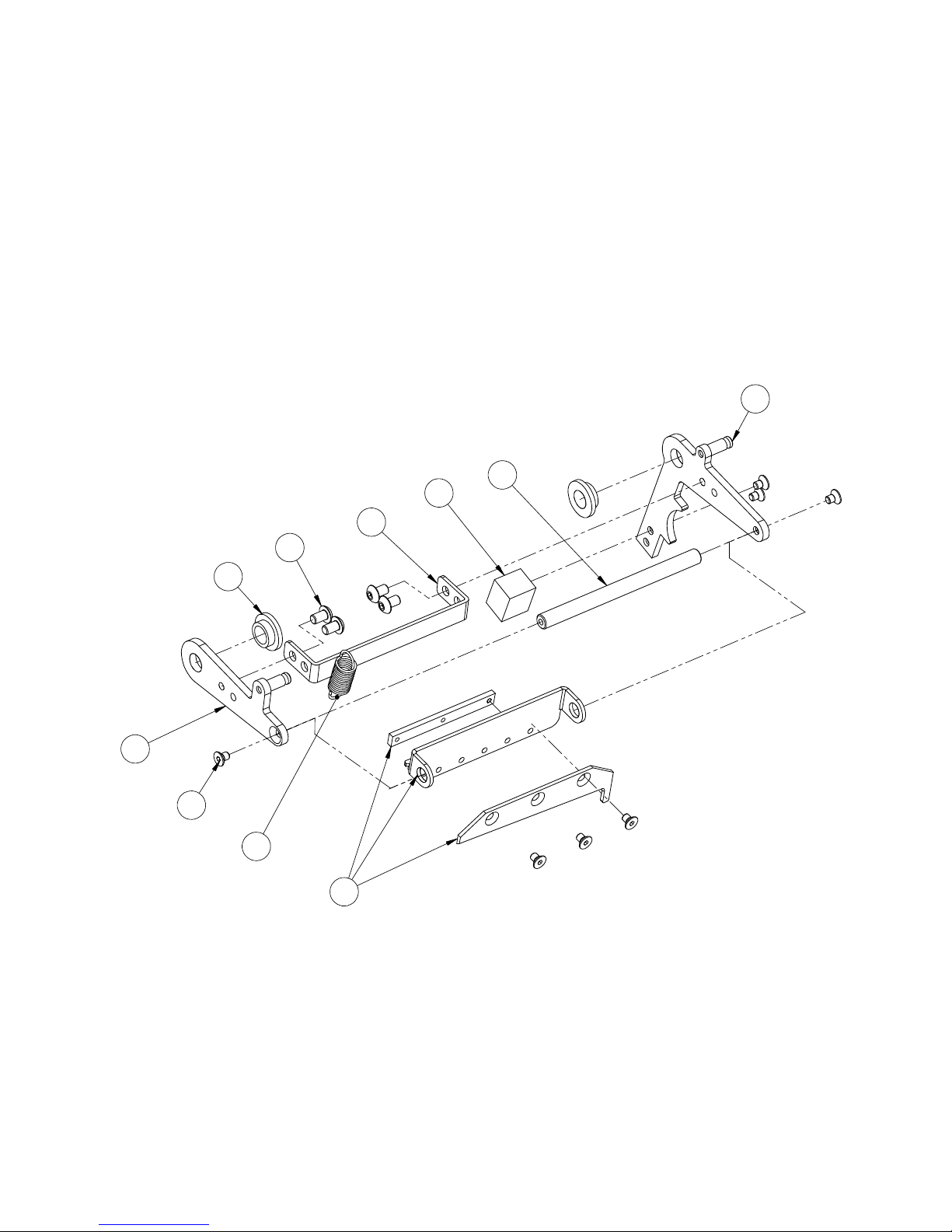
WST0014
2
8
6
3
4
10
1
5
7
9
Page 58

58
ITEM NO. PART NUMBER DESCRIPTION QTY.
1 WPT0046 WT Knife Arm Right Side 1
2 WPT0047 WT Knife Arm Left Side 1
3 WPT0052 WT Reinforcement Plate 1
4 WPT0004 OilliteFlange Bearing 10mm 2
5 WPT0055 WT Knife Arm Block 1
6 WPT0048 WT Knife Arm Pivot Shaft 1
7 WST0015 WT Cutter Blade SA 1
8 WPT0053 WT SPRING 1
9 UF6351 SS FHCS M4-0.7 x 6 mm 4
10 UF7010 SS BHCS M5 X 0.8 X 8MM 4
WST0014
Page 59
59
1
3
2
4
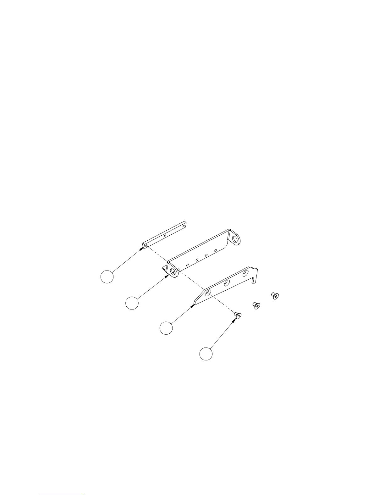
WST0015
Page 60

60
ITEM NO. PART NUMBER DESCRIPTION QTY.
1 WPT0049 WT Cutter Blade Support 1
2 WPT0050 WT Cutter Blade 1
3 WPT0051 WT Cutter Blade Lock Plate 1
4 UF6351 SS FHCS M4-0.7 x 6 mm 3
WST0015
 Loading...