

InternetVSAT.com StarPro1 Installation Manual
InternetVSAT.com
28
May
04
Installing and commissioning an RCST
InternetVSAT.com
Proprietary
Introduction
This document is intended for providing instructions on installing,
operating, and field servicing of the StarPro1 terminal system.
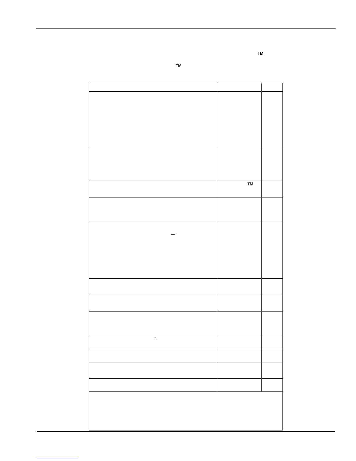
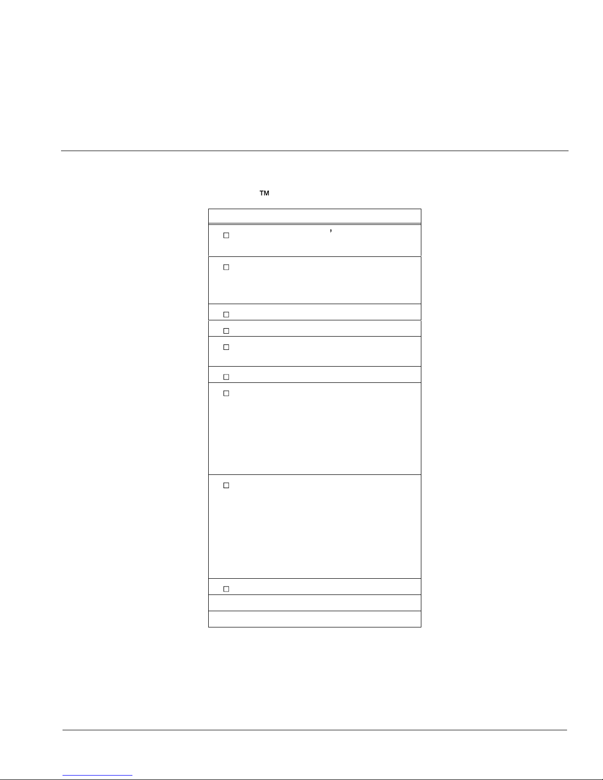
A typical StarPro1 remote terminal system consists of the following
components
Component
Part No.
Qty
1
1. Antenna
Location dependant must be
approved by
InternetVSAT
1
2. Non-penetrating Mount
TBC
1.2 m
Channel Master
611652302
1
3. RCST
StarPro1
terminal
1
4. BUC
2 W
JRC
NJT5024F or
5016
1
5. LNB:
W 3 & W1 DRO 10.95
11.7 Ghz
L.O. 10 Ghz
NJR
C21545A
NJR 2184
Norsat 4708
C
1
6. IFL Cables:RG11 75 Ohm low
loss
TBD
2
7. IFL Cable In
stallation Kit:
RG11 75 Ohm low loss
TBD
2
8. Adapter(s)
RG8 cable run
F male to N female
1
9. Tape, self
-fusing 6 (not supplied)
TBD
1
2
10. Grounding wire 8 AWG
1
2
11. Installation Kit, Indoor Unit, for rack
mount (optional)
1
3
12. DC power s
upply (optional)
1
3
1
Quantity is per line item.
2
Installer supplied
3
Optional requirements.
InternetVSAT.com
Proprietary
Below illustrates a StarPro1 remote system
Important note at any timework is carried
out on the TX or RX
unit the power to
the
indoor unit
must be turned
OFF
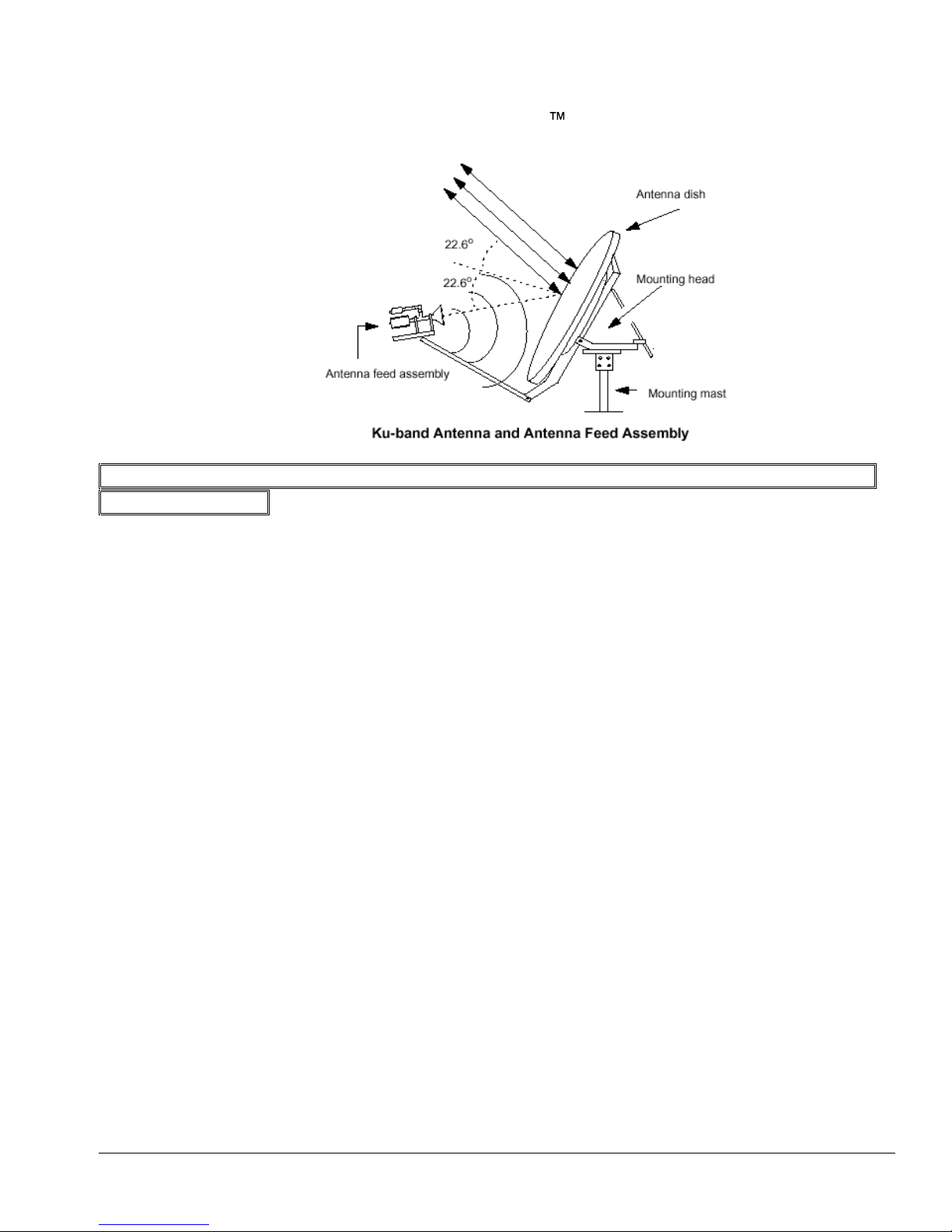
Antenna and Feed Assembly
Incoming signals from the satellite are int
ercepted by the antenna
reflector ("dish") and focused into the feed assembly. The feed
assembly collects receive signals and passes them to the LNB.
The anten
na geometry is termed an Offset Feed Parabola, with the
beam (satellite direction) typically orie
nted 22.6o above a line
perpendicular to the antenna face, as shown above. The antenna
mount allows the antenna to be pointed toward the satellite by pivoting
around the mounting mast (azimuth) and by tilting about the mounting
head (elevation). The entire
Antenna Assembly can be rotated about
the feed axis to set polarization.
Note that it is not a rule that an antenna offset is 22.6o. Refer to the
documentation that accompanies the antenna for the actual offset
specification.
LNB
The LNB provides the
low noise amplification and down conversion
from Ku-band or C-band to L-Band. The down converted signals are
then routed to the RCST via coaxial cable. Based on the satellite
downlink frequency bands, the LNB is available to receive the
frequencies as spe
cified below.
InternetVSAT.com
Proprietary
Atlantic Bird
W 3 & AB1
12649 Ku
1349 L
-Band
11554.41 Ku
1155.4 L-Band
BUC
The BUC (Block up converter) accepts transmit signals from the
RCST and provides up conversion to the satellite uplink frequency and
transmits them to the satellite
.
For the StarPro1
ODU, the BUC includes a Solid State Power Amplifier available as Ku-
Band
transceivers for .5-, 1-, 2-, or 4-Watt operation and as C-Band transceivers for 2
- and 5-
Watt
operation. The RCST provides a 24VDC source to power these units. For the 4-
Watt Ku-ba
nd
and 5-Watt C-band units, the RCST is equipped with an external power supply adapter to satisfy
the additional power requirement.
IFL Length
Cable
Connector
External Power
Supply
0 - 30m
RG-
6 type
F Type
No
30-50
m RG-11 type
F Type
No
Table 1: Cabl
ing Specifications for 2W C-band or 1W/2W KU-band BUC
IFL Length
Cable
Connector
External
Power
Supply
100m
RG-11 type F-type
Yes
Table 1: Cabling Specifications for 5W C-band or 4W KU-band BUC
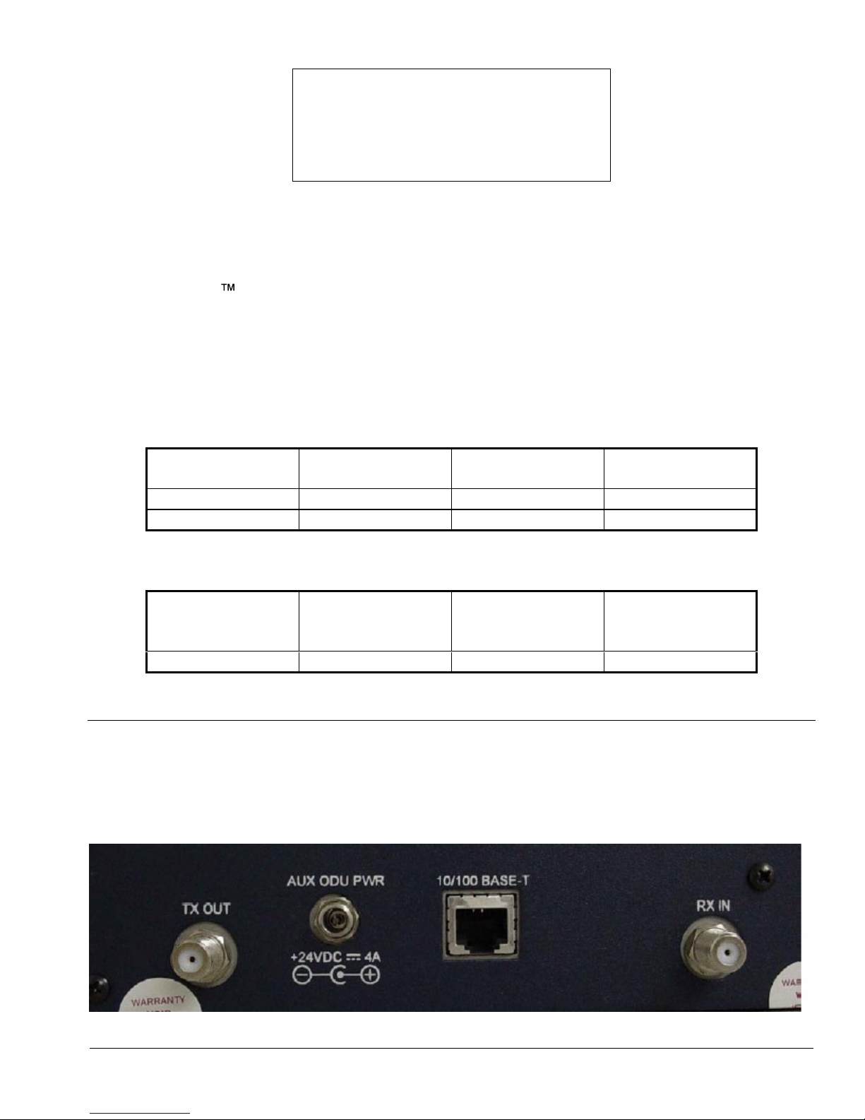
Return Channel Satellite Terminal (RCST)
The StarPro1 RC
ST combines a DVB receiver, a burst MF-TDMA modulator, and a terrestrial
traffic interface on a single integrated circuit board.
InternetVSAT.com
Proprietary
The RCST terrestrial interface is a standard 10/100BaseT. The TCP Acceleration processing
engine is built into the RCST soft
ware. The maximum aggregate TCP data transmission rate for
each RCST is 10Mbps.
The RCST comes with L-Band IF interfaces and can be rack-mounted. Depending upon the
satellite link requirements, the StarPro1 RCST is deployable in VSATs ranging from sub-met
er
0.96m/1-Watt Ku-band units to 2.4m/. 5-Watt C
-
Recommended Tools and Test Equipment
Below lists all recommended tools and test equipment for completing
a StarPro1 terminal system installation.
Description
Electronic Installer s Tool Kit
Multi mete
r
Cable Termination Tool Kit
Crimp tool for RG11 connectors
Cable stripper
Magnetic Compass
Inclinometer
Socket Set, 3/8" drive, to 3/4", with
3" extension
Set, Allen Keys
Test Equipment:
Satellite meter maximizing BER
& 10Mhz
span
Adapters
Type F female to N male
GPS for LAT/LONG
Laptop PC for use in terminal
configuration or troubleshooting,
running telnet sessions.
Minimum PC requirements: 10/100
Ethernet Card
Win98 or higher
Pentium processor
Standard LAN cross
over cable
Standard straight LAN cable
A rack mounted RCST must occupy 3U space where the top 2U space is left empty as to ensure
adequate cooling. Less space can cause overheating and failure of the terminal.
Similarly, a tabletop mounted RCST requi
res the placement to be cool and well ventilated. No
other items may be resting on top of the unit to ensure adequate cooling.
 Loading...