

International Thermal Research The WaterHeater Installation And Operating Manual

The WaterHeater™ by ITR
Installation and
Operating Manual
Continuous Domestic Hot Water Heater and Heating
System for Recreational Vehicles and Yachts

Copyright © June 2005
International Thermal Research
IN CANADA: IN THE UNITED STATES:
2431 Simpson Road Suite 260, 600 SE Maritime Ave.
Richmond, BC, Canada V6X 2R2 Vancouver WA USA 98661
Tel: 1-800-755-1272 or 604-278-1272 Tel: 1-800-993-4402 or 360-993-4877
Fax: 604-278-1274 Fax: 360-993-1105
Email: itr@shaw.ca Email: info@itrheat.com
Website: http://www.itrheat.com
All rights reserved. No part of this manual may be reproduced or
transmitted in any form by any means, electronic or mechanical,
including photocopying and recording, information storage,
retrieval, or transmission, without permission in writing from
International Thermal Research
Right to Modify:
Due to our commitment for quality and ongoing product
improvement, ITR reserves the right to modify or change
without notice, any materials, applications, equipment,
accessories, and/or prices. All measurements and weights are
approximate.

Table of Contents
Section 1, Overview...................................................1-1
1.1 Unpacking The WaterHeater™ by ITR.............. 1-1
1.2 Protect Your Warranty .................................. 1-2
1.3 The WaterHeater™ by ITR Features ................ 1-3
1.4 Critical Factors............................................. 1-4
1.5 Equipment, Tools and Skills........................... 1-5
1.6 Testing and Inspection.................................. 1-6
Section 2, Mounting - The WaterHeater™ .................2-1
2.1 Before You Begin ......................................... 2-1
2.2 Identifying The WaterHeater™ by ITR Model .... 2-2
2.3 Your Mounting Location................................. 2-2
2.4 What NOT to Do........................................... 2-4
2.5 Procedure ................................................... 2-5
Section 3, Installing the Exhaust System...................3-1
3.1 Before You Begin ......................................... 3-1
3.2 Mounting Location........................................ 3-1
Recommended Exhaust Outlet Locations............3-1
Recommendation for Installation ......................3-2
What NOT to Do............................................. 3-4
3.3 Procedure ................................................... 3-4
Section 4, Installing the Fuel System ........................4-1
4.1 Before You Begin ......................................... 4-1
4.2 Fuel System Operation.................................. 4-1
Recommendation for Installation ......................4-1
4.3 What NOT to Do........................................... 4-2
4.4 Procedure ................................................... 4-3
International Thermal Research iii

Table of Contents
Section 5, Installing Fan Heaters – With “Space
heating Module” Only................................................ 5-1
5.1 Before You Begin..........................................5-1
5.2 Fan System Operation...................................5-1
Features ....................................................... 5-2
Single Zone Heating ....................................... 5-3
Accessories and Components Needed................ 5-3
5.3 What NOT to Do ...........................................5-4
5.4 Mounting Locations.......................................5-4
5.5 Procedure....................................................5-5
Section 6, Wiring the Electrical System..................... 6-1
6.1 Before You Begin..........................................6-1
6.2 12 VDC .......................................................6-1
6.3 120 VAC......................................................6-2
6.4 Remote Operating Panel Cable........................6-2
6.5 Main Electronic Control Board.........................6-3
6.6 Space Heating Control Board (optional) ...........6-3
6.7 What NOT to Do ...........................................6-4
Section 7, Plumbing the System................................ 7-1
7.1 Before You Begin..........................................7-1
7.2 Plumbing Installation.....................................7-2
7.3 What NOT to Do ...........................................7-4
7.4 Installation Procedure ...................................7-4
Section 8, Operating The WaterHeater™ by ITR ........ 8-1
8.1 Operating Instructions for
The WaterHeater™ by ITR .............................8-1
8.2 Turning the Power to
The WaterHeater™ by ITR ON ........................8-2
8.3 Activing the Burner (Primary).........................8-2
8.4 Activating the Cabin Fan Heaters
through the Thermostats ...............................8-3
8.5 Functions of the Remote Operating Panel.........8-3
8.6 Functions of The WaterHeater™ by ITR
Control Panel ...............................................8-4
iv Installation and Operating Manual for The WaterHeater™ by ITR

Table of Contents
8.7 Functions of the Space Heating
Module (Optional) Zone Control Board............. 8-6
8.8 Maintenance................................................ 8-7
8.9 Protect The WaterHeater™ by ITR™ and
Space Heating Module (Optional)...................8-10
8.10 General Troubleshooting ..............................8-10
Section 9, Installing The Space Heating Module
(Optional)..................................................................9-1
9.1 Before you Begin.......................................... 9-1
9.2 Identifying Your Space Heating
(Optional) Model ......................................... 9-2
9.3 Your Mounting Location................................. 9-2
9.4 Selecting the Space Heating Module
Zone Box Location........................................ 9-3
9.5 Plumbing Installation.................................... 9-3
9.6 Electrical Connection .................................... 9-7
9.7 Space Heating Zone Board ............................ 9-7
9.8 What NOT to Do..........................................9-10
9.9 Procedure ..................................................9-10
9.10 INSPECTION AND TESTING ..........................9-10
Section 10, Warranty Information
International Thermal Research v

Table of Contents
List of Figures
Figure 1-1 Hot Water Heater and
Space Heating Module (Optional)..................1-1
Figure 2-1 Dimensions ...............................................2-4
Figure 2-2 Location of Mounting Brackets
Insets: Bracket/Nut/Bolt Configurations........2-5
Figure 3-1 Installing the Exhaust System (Up Exhaust)...3-5
Figure 3-2 The Exhaust Goose Neck Configuration..........3-5
Figure 5-1 Wiring the Fan’s Aquastat............................5-2
Figure 5-2 Mounting a Spacesaver Fan .........................5-5
Figure 5-3 Installing a Relay for Add’l Fan Amperage ......5-6
Figure 6-1 System Wiring ...........................................6-3
Figure 7-1 Plumbing Fittings........................................7-2
Figure 7-2 The Approved Method of Installing
Heater Hose (Consult ITR for Alternative
Methods and Products)................................7-5
Figure 8-1 The WaterHeater™ by ITR – Fittings .............8-1
Figure 8-2 Remote Operating Panel..............................8-3
Figure 8-3 The WaterHeater™ by ITR – Control Panel .....8-5
Figure 9-1 Space Heating Module Plumbing Fittings........9-3
Figure 9-2 Space Heating Module and
Hot Water Heater Hookup............................9-5
Figure 9-3 Space Heating Module and Zone
Board Electrical Hookup...............................9-8
vi Installation and Operating Manual for The WaterHeater™ by ITR
Section
1
Overview
Thank you for purchasing The WaterHeater™ by ITR for recreational
vehicles and marine yachts.
Some of the figures
in this manual
represent a typical
installation, but
other configurations
or methods may be
acceptable. If in
doubt, obtain
approval from ITR.
This section describes features of The WaterHeater™ by ITR and covers
critical information you need to know before beginning the installation,
including how to protect your warranty, and tools and equipment
eeded. n
1.1 Unpacking The WaterHeater™ by ITR
When you receive The WaterHeater™ by ITR:
International Thermal Research 1-1
1 Unpack it carefully.

Section 1, Overview
f
2 Check each component against the provided parts list to ensure that
you have everything and that all parts arrived undamaged.
3 If you discover any missing or defective parts, call ITR immediately.
4 If you are not installing The WaterHeater™ by ITR right away, secure
all components so none will be misplaced.
5 Before installing The WaterHeater™ by ITR, read the rest o
Section 1 – Overview. It contains critical information for a
proper installation.
A properly installed WaterHeater™ by ITR is essential for several
reasons:
• To ensure that you and/or your customers receive satisfactory
results.
• To ensure a trouble-free installation, a successful inspection and
testing process and ease of future maintenance.
• To protect your Warranty.
NOTICE
1.2 Protect Your Warranty
This document reflects approved installation techniques, methods, and
materials, and applies only to ITR equipment. The WaterHeater™ by
ITR is only guaranteed by ITR if the entire system has been installed
according to the requirements and recommendations set out here.
Any modification must be approved in writing by qualified ITR
personnel, prior to the installation.
This includes:
• Deviations from the instructions in this Manual.
• Changes to any piece of ITR-supplied equipment.
• Substitution of a non-ITR-approved component.
No warranty will be extended to improper installations. Use of any
unapproved materials, equipment, or installation procedures will result
in a voided warranty for the entire heating system. ITR accepts no
liability for
modifications.
any damage or loss of service resulting from unapproved
1-2 The WaterHeater™ by ITR
Section 1, Overview
• Efficient
• Clean
• Quiet
• Compact
• Safe
• Rugged
• Reliable
• Economical
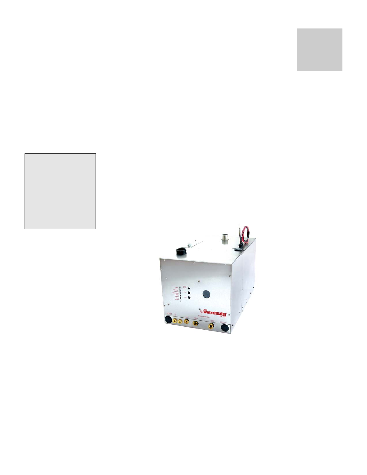
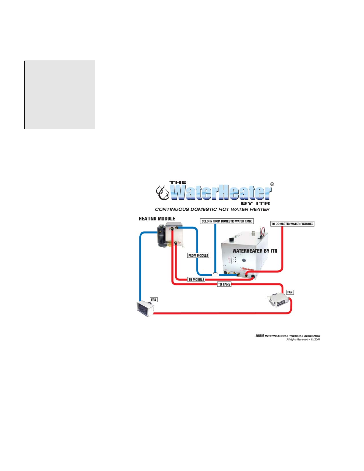
1.3 The WaterHeater™ by ITR Features
The WaterHeater™ by ITR uses a patented diesel burner (12 VDC)
controlled by a multi-functional electronic controller as the primary
source of heating water. A single 1500 watt, 120 VAC immersion
element is used as a secondary heat source (240 VAC also available).
The WaterHeater™ by ITR heats water to provide a continuous supply
for all domestic hot water needs. The WaterHeater™ by ITR can also
provide a single zone of space heating using the Space Heating Module
(optional). See Figure 1-1.
Figure 1-1: Hot Water Heater and Space Heating Module (Optional)
International Thermal Research 1-3

Section 1, Overview
Other features of The WaterHeater™ by ITR include:
• A high-temperature, stainless steel burner and stainless steel
jacket.
• 5.3 US gallon ( 20.5 l) welded stainless steel insulated wate r tank
that minimizes heat loss and optimizes heat recovery.
• Low water level switch in the tank.
• Easy to install with hookups and connections easily accessible
from the top and front of The WaterH eater™ by ITR.
• Quiet operation and low power consumption.
• Low pressure fuel system with built-in fuel pump.
• Fuel efficient burner capable of burning a wide variety of diesel-
based fuels.
• Exhaust has minimal smoke or smell.
• Fan assisted sealed combustion chamber is designed to use
outside air.
• Simple, low amperage draw ignition.
• Electronically-controlled system with:
o Automatic Safety Shutdown.
o Manual reset aquasta ts for safety overheat protection.
o LED indicators on the Control Panel for diagnostics.
o Patented, proprietary flame sensor.
• The WaterHeater™ by ITR Remote Operating Panel with ON/OFF
switch for the diesel burner and indicator LED’s for operational
and diagnostic information.
1.4 Critical Factors
Pay attention to the
notices of “Danger”
“Warning” “Caution”
and “Notice” in this
manual.
The key factors to keep in mind when planning and carrying out the
installation are:
• Mounting location restrictions for The WaterHeater™ by ITR,
Space Heating Module (optional), and exhaust outlet (to reduce
noise, vibration, heat loss, etc.)
1-4 The WaterHeater™ by ITR

Section 1, Overview
• Length, routing, and sizing of fluid lines, fuel lines, air flow tubing,
exhaust piping and wiring.
• Unrestricted intake required to draw in outside air for combustion.
• Ability to easily access and service the product, especially fuel,
plumbing, and electrical systems.
• After installation, requirement to purge water and fuel lines and
inspect/test entire system using the ITR-supplied Inspection
Check Sheet.
1.5 Equipment, Tools and Skills
As the user and/or installer, you must be qualified and authorized to do
the installation, which requires mechanical aptitude and electrical
knowledge. Make sure you comply with existing RVIA or ABYC industry
practices, using the highest and most recent standards and codes.
Good workmanship is essential. Please refer back to Section 1.2,
Protect Your Warranty.
You will need the following equipment and tools (not supplied) to install
the heating system. This list does not include optional equipment and
accessories:
• Standard tools normally available in a well-equipped shop.
• Appropriate fasteners for mounting the heater unit.
• Stainless steel 1-1/2” ID exhaust piping, maximum 12’ with no
bends (see Section 3 – Installing the Exhaust System, for details
when bends are present).
• ITR muffler.
• 1/4” supply and return fuel line, approved rubber or copper.
• Heater hose (to connect Space Heating Module [optional] hose
fittings to interior fans).
• Domestic water hose and/or tu bing to connect The WaterHeater™
by ITR hose fittings to the domestic water system.
International Thermal Research 1-5

Section 1, Overview
1.6 Testing and Inspection
After all components have been properly installed according to standard
practices, RVIA or ABYC standards, and the recommendations of this
Installation and Operating Manual, The WaterHeater™ by ITR should be
test-operated for inspection purposes.
For your convenience, you can use the pullout Inspection Check Sheet in
this Manual. The Inspection Check Sheet is divided into progressive
sections, allowing each phase of the inspection to be carried out
systematically, and then signed off by authorized persons.
1-6 The WaterHeater™ by ITR

Section
2
Mounting - The WaterHeater™
2.1 Before You Begin
Plan the location of The WaterHeater™ by ITR and all its major
components in advance to ensure the chosen locations are feasible
and within the technical specifications.
Consider the following factors to help you decide exactly where
best to mount The WaterHeater™ by ITR:
• The WaterHeater™ by ITR weight when full.
! WARNING
• Ventilation requirements.
• Exhaust outlet location and maximum acceptable length.
• Thru hull location.
• Potential for vibration and jarring.
• Fuel storage location.
• Most efficient plumbing runs.
• Safe and convenient access for maintenance.
• Number and location of interior fans.
• Location of other equipment to be installed or connected to
The WaterHeater™ by ITR, including Space Heating Module,
Zone Control Box, heat exchangers, overflow tank,
batteries, etc.
Make sure you are familiar with Section 1 – Overview of this
Manual. If the system is not installed according to specifications
and with the correct equipment, The WaterHeater™ by ITR may
not operate properly, safety may be compromised, and your
Warranty may be voided.
International Thermal Research 2-1

Section 2, Mounting The WaterHeater™ by ITR
2.2 Identifying The WaterHeater™ by ITR
Model
As the owner, you must be fully aware of the controls and
operating features particular to your model of The WaterHeater™
by ITR. This is essential for the proper functioning and life of The
WaterHeater™ by ITR as well as protecting your warranty. Your
model can be identified by locating the serial number label on the
outside case of The WaterHeater™ by ITR. The serial number
identifies the model type through the first series of letters and
numbers.
The types of The WaterHeater™ by ITR models are:
HWH – The WaterHeater™ by ITR
! CAUTION
2.3 Your Mounting Location
Your mounting location should consider the following:
• Mounting location must be able to support double the
gross weight of The WaterHeater™ by ITR (i.e.
150 lbs. x 2 = 300 lbs/68 KG x 2 = 136 KG) and mu st b e
of a non-combustible surface.
• The WaterHeater™by ITR is 14”H x 14”W x 24”D
(35.6 cm x 35.6 cm x 60.9 cm). See Figure 2-1:
Dimensions.
The WaterHeater™ by ITR must not be installed in any compartment with flammable gases.
• The WaterHeater™ by ITR must be completely isolated
from living spaces. Combustion air must be drawn from
an outside source and cannot contain any combustible
gases.
• The WaterHeater™ by ITR must be mounted in an area
that provides unrestricted access to the front panel
mounted fuel and water connections, and top mounted
power and exhaust connection (minimum of 10” top
clearance – top exhaust version; and, minimum of 6” top
clearance – bottom exhaust version) and 3” clearance to
all other WaterHeater™ surfaces.
2-2 The WaterHeater™ by ITR

Section 2, Mounting The WaterHeater™ by ITR
• The WaterHeater™ by ITR must not be installed in any
compartment with flammable gases.
• The WaterHeater™ by ITR must be mounted horizontal and
level using eight (8) x 1/4” through bolts and 1” diameter
fender washers, lock washers and nuts.
• It is recommended that a catchpan be placed under The
WaterHeater™ by ITR for containing any unexpected
leakage.
NOTICE
If The WaterHeater™ by ITR is going to be mounted in the engine
compartment, check for adequate ventilation. When the engine is
running, this area could be under a negative pressure. Make sure
the air intake and exhaust hoses have no leaks and are wellfastened to the heater, muffler and thru hull fitting. Assembly
parts that may cause injury through accidental contact should be
protected.
Isolate the unit in a closed compartment so that no air from the
heater will infiltrate the living areas.
• Choose a sturdy surface in a location that won’t be unduly
affected by vibration and the jarring of rough roads or rough
seas.
• Mount the unit with the front panel side facing out and
accessible. Facing out simplifies installation and
maintenance.
• Open access is required to properly service the heater.
Leave room at the front, and top of the unit.
• Ensure that the exhaust tubing can be properly and safely
routed to the outside. The maximum exhaust run for the
system is 12’.
International Thermal Research 2-3
Section 2, Mounting The WaterHeater™ by ITR
Figure 2-1: Dimensions
2.4 What NOT to Do
• Don’t mount The WaterHeater™ by ITR in the rear of the
coach or yacht underneath the sleeping area. The sound of
The WaterHeater™ by ITR cycling on and off may disturb
light sleepers.
2-4 The WaterHeater™ by ITR
Section 2, Mounting The WaterHeater™ by ITR
2.5 Procedure
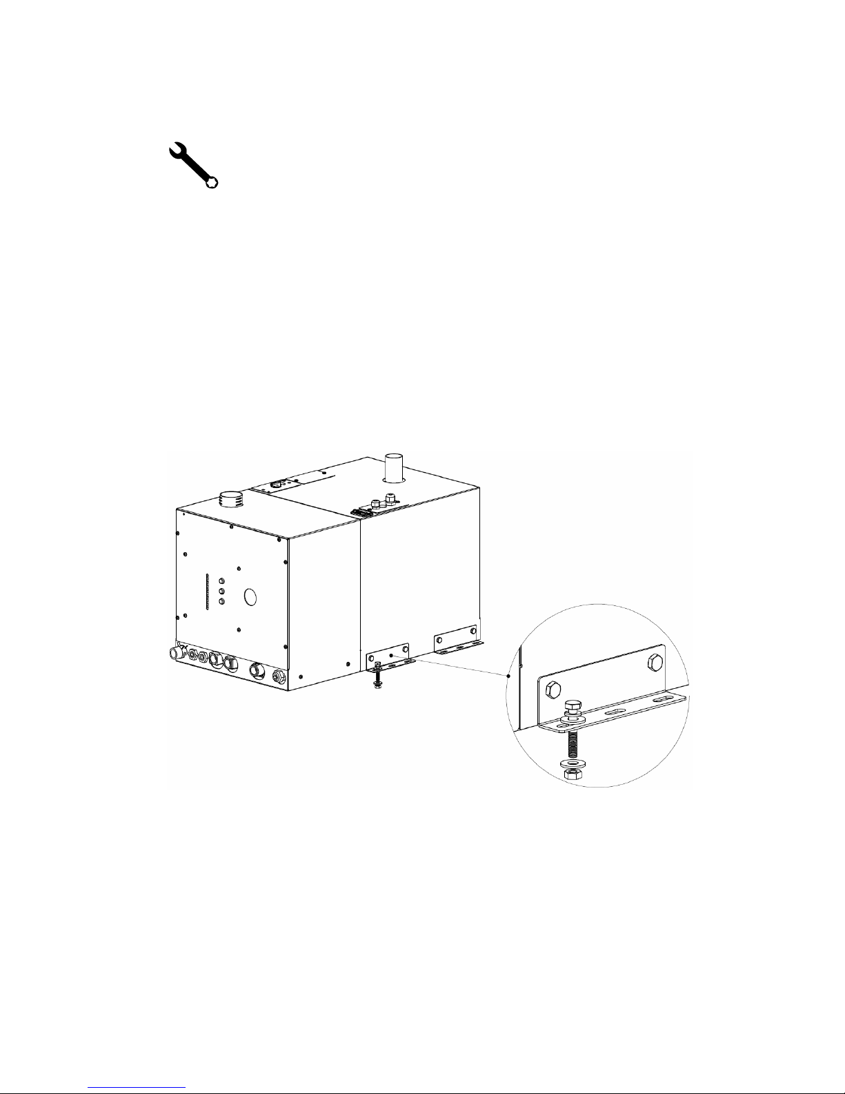
After choosing the mounting location for The WaterHeater™ by
ITR:
1
Mount The WaterHeater™ by ITR horizontally and level.
2 Secure The WaterHeater™ by ITR in place (against the wall,
floor, or a mounting platform) and eight (8) x 1/4” through
bolts and 1” diameter fender washers, lock washers and nuts
(See Figure 2-2: Location of Mounting Brackets.).
Figure 2-2: Location of Mounting Brackets.
Insets: Bracket/Nut/Bolt Configurations
International Thermal Research 2-5

Section
3
Installing the Exhaust System
3.1 Before You Begin
For efficient and safe operation of The WaterHeater™ by ITR
follow all recommendations for properly installing the exhaust.
Any deviations from these must be approved in advance by ITR.
Although the heater’s exhaust produces very low carbon
! DANGER
monoxide emissions, caution is still advised:
• Do not operate The WaterHeater™ by ITR in an enclosed
area unless there is adequate ventilation.
• Isolate The WaterHeater™ b y ITR in a closed compartment
so that no air from the unit will infiltrate the living areas.
Never place any exhaust parts close to combustible material or
through a combustible wall or ceiling without fireproof p rotection.
The exhaust can reach high temperatures.
3.2 Mounting Location
If you can’t meet the technical specifications for mounting
the exhaust, don’t use The WaterHeater™ by ITR. The unit
may perform poorly or become damaged if not installed
according to specifications.
Recommended Exhaust Outlet Locations
The following is recommended for a coach exhaust outlet
location:
• Mount the exhaust outlet outside the coach, not inside
the heater compartment. Otherwise, exhaust fumes could
infiltrate the coach from The WaterHeater™ by ITR
compartment.
International Thermal Research 3-1

Section 3, Installing the Exhaust System
• In a coach, the typical mounting location for the exhaust
outlet is under the floor of the heater compartment (see
Figure 3-1), or on the other side of the coach, directly
across from the heater unit. Keep in mind you cannot
exceed 12’ of exhaust piping, including bends.
• Position the outlet of the exhaust pipe so that the exhaust
exits off the side of the coach, not towards the front, back,
directly underneath the coach, or under an openable
window, vent or slide-out.
In a yacht installation, the following is recommended for the
exhaust outlet location:
• Make sure that the thru hull is at least 30” above the water
line with a goose neck rise on the exhaust to help eliminate
water from getting to The WaterHeater™ by ITR through
the exhaust. If the dual exhaust air-intake thru hull is
used, ensure that the air-intake is placed between
10 o’clock and 2 o’clock and also goose-necked to avoid
water ingestion, see Figure 3-2.
• There needs to be a 1/8" air gap around the exhaust thru
hull. The standard thru hull is 3" in diameter. The hole for
the fitting should be 3-1/4". Make sure that the holes for
the mounting screws have enough material left to properly
bite. The fitting must be centered in the hole.
Recommendation for Installation
The following applies to both a coach and yacht:
• You may use sweep bends but each 90° bend is equ ivalent
to one foot of exhaust piping. For example, if you use two
90° bends you must deduct one foot per bend from the
maximum allowed 12’ straight exhaust pipe length.
Therefore you will be restricted to 10’ of straight exhaust
piping plus the two bends. Do not exceed these
recommendations.
• Combustion air must be drawn from outside the coach or
yacht.
• Use an ITR-manufactured muffler; no other muffler is
acceptable.
• Exhaust outlet is on the top o r bottom (model dependant)
of The WaterHeater™ by ITR, towards the back.
3-2 The WaterHeater™ by ITR

Section 3, Installing the Exhaust System
The exhaust and outlet are HOT and the surrounding
! DANGER
areas must be thermally shielded and protected from the
hot surfaces and heat buildup by insulation. Nothing can
come into inadvertent contact with any part of the
exhaust system
• Exhaust pipe must have a minimum of 3” (7.6 cm)
clearance from all surfaces.
• Ensure that the exhaust cannot be plugged or restricted.
• The exhaust fitting on The WaterHeater™ by ITR is
1.5” O.D. and the exhaust pipe used must have a
minimum of 1.5” I.D throughout its length.
• All exhaust elbows must be of a large radius design
(minimum radius 2.0”).
• The exhaust must be supported a minimum of e very 3’ of
its installed length.
• The exhaust and The WaterHeater™ by ITR connection
point must use appropriate clamps and sealing compound
to ensure that the connections are tight and leak free. The
WaterHeater™ by ITR exhaust outlet pipe and the exhaust
pipe itself must not be distorted or damaged during this
process.
• When The WaterHeater™ by ITR is running, the connection
points and the system must be checked for leaks and any
found must be corrected. Periodically, check the exhaust
fittings, connections, exhaust tube and insulation for leaks
and integrity and correct if required.
• Appropriate exhaust insulation must be used to cover th e
entire length of any interior exhaust run.
• Solid stainless steel exhaust tubing is recommended but
an approved stainless steel flexible exhaust tubing can be
used. If flexible exhaust tubing is used the exhaust tubing
must be inspected regularly for leaks and deterioration as
this type of exhaust does not have the life expectancy of
solid tubing. Stepped band clamps are recommended for
joining flex and solid tubing as they apply firm, even
pressure.
• In a coach, install an exhaust collar on th e exhaust pipe to
isolate the pipe from the coach.
International Thermal Research 3-3
 Loading...