

International Thermal Research OASIS Chinook Installation And Operating Manual

OASIS® Chinook Heating
System
Installation and
Operating Manual
Diesel and AC Heating System
for Recreational Vehicles and Mobile Homes
CAN/CSA-C22.2 No.110-94 (R2014)
CSA B140.10-06 (R2015), CSA B140.0-03 (R2018)
UL307A (Edition 9), UL174 (Edition 11)

Copyright © August 2018
International Thermal Research
IN CANADA: IN THE UNITED STATES:
2431 Simpson Road 5305 NE 121st Ave, Suite 401
Richmond, BC, Canada V6X 2R2 Vancouver, WA, USA 98682
Tel: 1-800-755-1272 or 604-278-1272 Tel: 1-800-993-4402 or 360-993-4877
Fax: 604-278-1274 Fax: 360-993-1105
Email: info@itrheat.com
Website: http://www.itrheat.com
All rights reserved. No part of this manual may be reproduced or
transmitted in any form by any means, electronic or mechanical,
including photocopying and recording, information storage,
retrieval, or transmission, without permission in writing from
International Thermal Research
Right to Modify:
Due to our commitment for quality and ongoing product
improvement, ITR reserves the right to modify or change
without notice, any materials, applications, equipment,
accessories, and/or prices. All measurements and weights are
approximate.

Table of Contents
Section 1, Overview................................................. 1-1
1.1 Unpacking the Oasis® Chinook Heating System. 1-2
1.2 Protect Your Warranty .................................. 1-2
1.3 Oasis® Chinook Heating System Features......... 1-3
1.4 Critical Factors ............................................ 1-5
1.5 Equipment, Tools and Skills ........................... 1-6
1.6 Testing and Inspection.................................. 1-7
Section 2, Mounting the Oasis® Chinook Heating
System.................................................................... 2-1
2.1 Before You Begin ......................................... 2-1
2.2 Identifying Your Oasis® Chinook Heating System
Model ..................................................... 2-2
2.3 Your Mounting Location................................. 2-2
2.4 What NOT to Do .......................................... 2-4
2.5 Oasis® Chinook Mounting Procedure................ 2-4
2.6 Zone Control Board Mounting Procedure .......... 2-5
2.7 Remote Operating Panel Mounting Procedure.... 2-6
Section 3, Installing the Exhaust System.................. 3-1
3.1 Before You Begin ......................................... 3-1
3.2 Mounting Location........................................ 3-1
Recommended Exhaust Outlet Locations..................3-1
Recommendation for Installation ............................3-2
What NOT to Do ...................................................3-4
3.3 Procedure ................................................... 3-4
Section 4, Installing the Fuel System ....................... 4-1
4.1 Before You Begin ......................................... 4-1
4.2 Fuel System Installation................................ 4-1
Recommendations for Installation...........................4-1
4.3 What NOT to Do .......................................... 4-2
4.4 Procedure ................................................... 4-3
iv

Table of Contents
Section 5, Installing Fan Heaters.............................. 5-1
5.1 Before You Begin......................................... 5-1
5.2 Fan System Operation.................................. 5-2
Features ..............................................................5-2
Multiple Zone Heating ...........................................5-3
Accessories and Components Needed......................5-3
5.3 What NOT to Do .......................................... 5-4
5.4 Mounting Locations ...................................... 5-4
5.5 Procedure................................................... 5-5
Section 6, Wiring the Electrical System..................... 6-1
6.1 Before You Begin......................................... 6-1
6.2 Oasis® Chinook 12 VDC ................................ 6-2
6.3 Oasis® Chinook 120 VAC............................... 6-3
6.4 Wiring The Zone Control Board ...................... 6-4
Cabin Fan Leads .......................................... 6-4
Thermostat Leads........................................ 6-5
6.5 What NOT to Do .......................................... 6-5
Section 7, Plumbing the System ............................... 7-1
7.1 Before You Begin......................................... 7-1
7.2 Coolant Plumbing Installation ........................ 7-2
7.3 What NOT to Do .......................................... 7-4
7.4 Coolant Plumbing Installation Procedure.......... 7-5
7.5 Potable Water Plumbing Installation................ 7-6
7.6 Engine Plumbing Installation ......................... 7-7
7.7 Procedure For Filling/Purging The Oasis® Chinook
Heating System .......................................... 7-8
International Thermal Research

Section 8, Operating the Oasis® Chinook Heating
System.................................................................... 8-1
8.1 Features of your Oasis® Chinook Heating
System ...................................................... 8-1
8.2 Operating Instructions for the
Oasis® Chinook Heating System ..................... 8-3
8.3 Turning the Power to the
Oasis® Chinook Heating System ON ................ 8-4
8.4 Activating the Burner and AC Heat from the
Remote Operating Panel................................ 8-5
8.5 Activating the Cabin Fan Heaters
through the Thermostats............................... 8-6
8.6 Activating the Potable Hot Water .................... 8-6
8.7 Potable Water Temperature Adjustment........... 8-7
8.8 Activating the Engine Heat & Pre-heat ............. 8-8
8.9 Functions of the Remote Operating Panel......... 8-9
8.10 Functions of the Oasis® Chinook Control
Panel ....................................................... 8-11
8.11 Functions of the Zone Control Board ............. 8-12
8.12 Potable Water and Space Heating Priority ...... 8-14
8.13 Maintenance ............................................. 8-15
8.14 Protecting the Heating System ..................... 8-17
8.15 General Troubleshooting ............................. 8-18
Warranty Information & Warranty Card
vi

Table of Contents
List of Figures
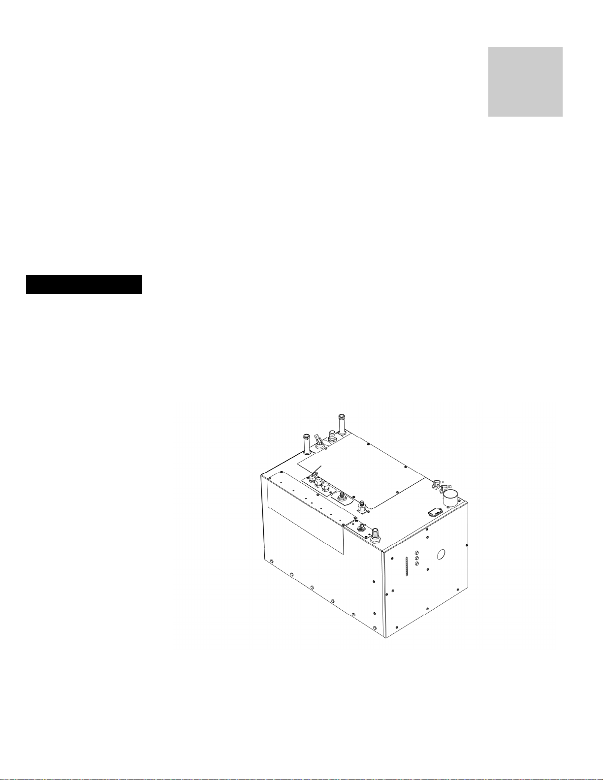
Figure 1-1 Oasis® Chinook Heating System ................ 1-1
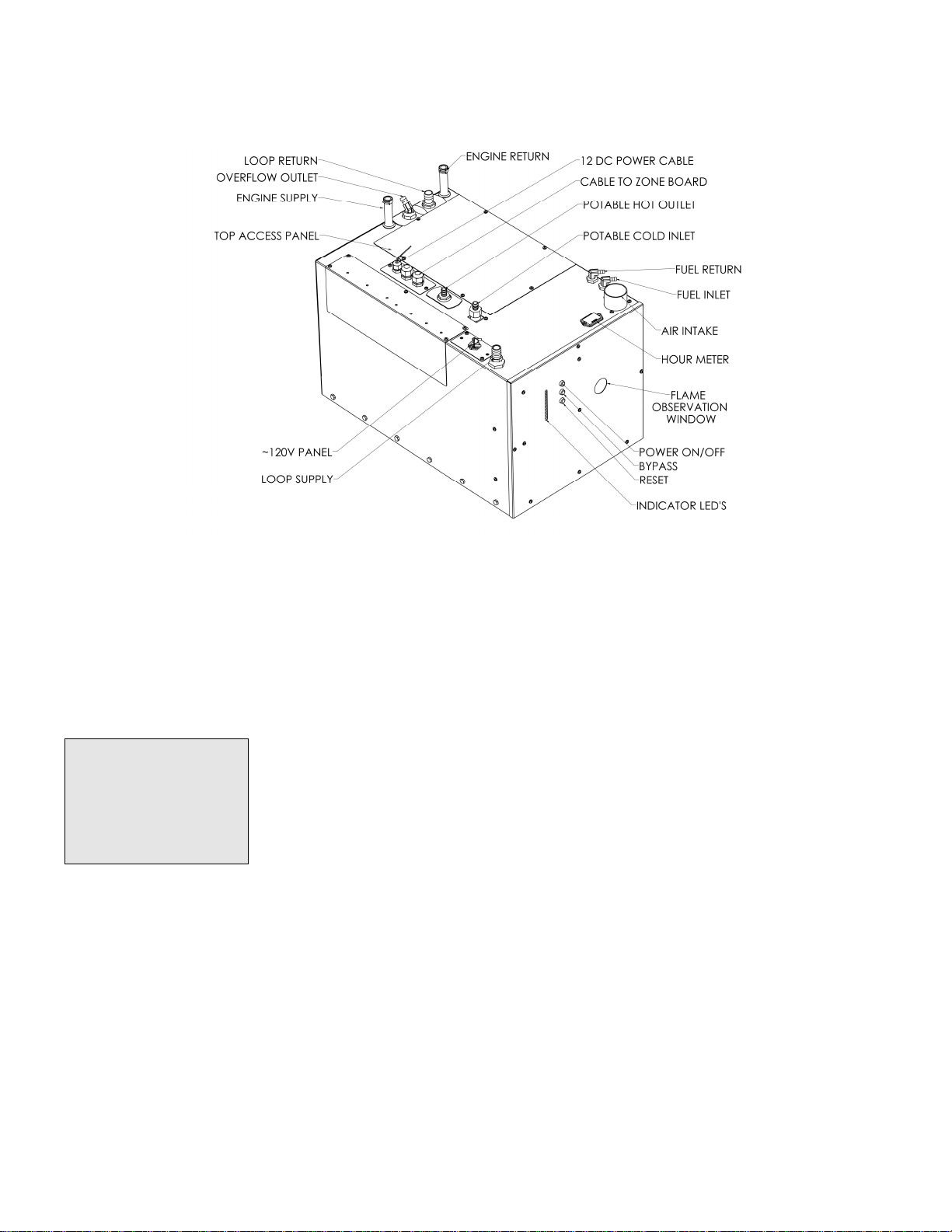
Figure 1-2 Oasis® Chinook Heating System Overview... 1-5
Figure 2-1 Oasis Chinook Heating Dimensions............. 2-3
Figure 2-2 Oasis Chinook Mounting Brackets .............. 2-5
Figure 2-3 Zone Control Board ................................. 2-6
Figure 2-4 Remote Operating Panel Mounting ............. 2-6
Figure 2-5 Touchscreen Operating Panel Mounting....... 2-7
Figure 3-1 Installing the Exhaust System ................... 3-6
Figure 3-2 The Exhaust Hole Location & Mounting
Template ............................................... 3-6
Figure 5-1 Wiring the Fan’s Aquastat......................... 5-2
Figure 5-2 Mounting a Low Profile Cabin Fan............... 5-6
Figure 5-3 Installing a Relay for Add’l Fan Amperage ... 5-6
Figure 6-1 System Wiring ........................................ 6-2
Figure 7-1 Oasis® Chinook Overview ......................... 7-3
Figure 7-2 Plumbing Oasis® Chinook For 5 Zones ........ 7-3
Figure 7-3 Three Approved Methods of Installing
Heater Hose ........................................... 7-6
Figure 7-4 Potable Hot Water System Plumbing .......... 7-7
Figure 7-5 Engine Heat / Pre-heat System Plumbing .... 7-8
Figure 7-6 Filling/ Purging Oasis® Chinook Heating ...... 7-9
Figure 8-1 Oasis® Chinook Heating System Overview... 8-3
Figure 8-2 Oasis® Chinook Main Control Panel............. 8-4
Figure 8-3 Mixing valve location ............................... 8-7
Figure 8-4 Remote Operating Panel.......................... 8-9
Figure 8-5 Zone Control Board ............................... 8-13
Figure 8-6 Zone Control Board Proority Jumper......... 8-15
International Thermal Research
Section
NOTICE
1
Overview
Thank you for purchasing the Oasis® Chinook Heating System for
recreational vehicles.
The Oasis® Chinook Heating System is CSA/UL certified only
for installation into Recreational Vehicles, Manufactured
Homes, and Mobile housing.
This section covers critical information you need to know before
beginning the installation including how to protect your Warranty,
and tools and equipment needed.
International Thermal Research 1-1
Figure 1-1: Oasis® Chinook heating system

Section 1, Overview
call ITR
right
read
1.1 Unpacking the Oasis® Chinook Heating
System
When you receive the Oasis® Chinook Heating System:
1 Unpack it carefully.
2 Check each component against the shipping list to ensure that
you have everything and that all parts arrived undamaged.
3 If you discover any missing or defective parts
immediately.
4 If you are not installing the Oasis® Chinook Heating System
away, secure all components so none will be misplaced.
5 Before installing the Oasis® Chinook Heating System
the rest of this Installation and Operating Manual. It
contains critical information for a proper installation.
A properly installed Oasis® Chinook Heating System is essential for
several reasons:
· To ensure that you and/or your customers receive satisfactory
results and enjoy a warm, comfortable environment.
· To ensure a trouble-free installation, a successful inspection and
testing process, and ease of future maintenance.
· To protect your Warranty.
1.2 Protect Your Warranty
This document reflects approved installation techniques, methods,
and materials, and applies only to ITR equipment. The Oasis®
Chinook Heating System is only guaranteed by ITR if the entire
system has been installed according to the requirements and
recommendations set out here.
This includes:
· Deviations from the instructions in this Manual.
· Changes to any piece of ITR-supplied equipment.
· Substitution of a non-ITR approved component.
1-2 The Oasis® Chinook Heating System

Section 1, Overview
No Warranty will be extended to improper installations. Use of any
unapproved materials, equipment or installation procedures will
result in a voided warranty for the entire heating system. Any loss
of service or damage as a result of any unapproved modification is
the responsibility of the installer. ITR accepts no liability for any
damage or loss of service resulting from unapproved modifications.
• Efficient
• Clean
• Quiet
• Compact
• Safe
• Rugged
• Reliable
• Economical
1.3 Oasis® Chinook Heating System
Features
The Oasis® Chinook Heating System uses a 50,000 BTU (true
output) diesel burner (12 VDC) controlled by a multi-functional
electronic controller as the primary source of heating coolant fluid
(anti-freeze and water). Two 1500 Watt, 120 VAC immersion
elements are used as secondary heat sources to provide an
additional 10,000 BTU of heat. The Oasis® Chinook Heating System
heats the coolant fluid to provide a source of heat for all hydronic
space heating needs. Through the use of its integral distribution
pumps, the Oasis® Chinook Heating System has the ability to
circulate the coolant fluid to all space heating areas. It can also
provide a supply of potable hot water using the integral heat
exchanger. The Oasis® also incorporates engine heat and preheat
(optional) functions. (see Figure 1-2: Oasis® Chinook Heating
System).
Other features of the Oasis® Chinook Heating System include:
· Built in distribution pumps and heat exchanger for heating
multiple zones and also producing potable hot water. Heat
exchanger also allows engine pre-heating (optional) as well as
using engine waste heat. The Zone Board Controls up to five
space heating zones.
· Support for potable hot water demand. The mixing valve is
factory set to limit the maximum temperature of the heated
potable water to 120ºF (49°C) with a total hot water demand of
1.5 GPM or less, and an incoming water temperature of 60ºF
(16ºC) or higher.
· Easy to install and field serviceable with system hookups and
connections easily accessible from the top of the heater.
· Easy to fill and purge zero pressure system.
International Thermal Research 1-3

Section 1, Overview
· Easy to drain.
· A high-temperature, stainless steel burner and stainless steel
jacket.
· 7 US gallon, welded, insulated stainless steel coolant tank that
minimizes heat loss and optimizes heat recovery.
· Domestic water flow switch for quick response to domestic hot
water demand.
· Low coolant level switch.
· Quiet operation and low power consumption.
· Low pressure fuel system with built-in fuel pump.
· Fuel efficient burner capable of burning a wide variety of diesel-
based fuels (CSA/UL certified for diesel #1 and #2).
· Exhaust has minimal smoke and smell.
· Fan assisted sealed combustion chamber is designed to use
outside combustion air.
· Low amperage draw ignition.
· Electronically-controlled system featuring:
· automatic Safety Shutdown;
· manual-resettable aquastats for safety overheat protection.
· LED indicators on the Control Panel for diagnostics.
· Patented, proprietary flame sensor.
· Remote Operating Panel with ON/OFF switch for the diesel
burner, AC elements, and engine pre-heat, if installed.
· Control Panel with buttons for Power, Bypass, Reset, and
indicator LED’s for operational and diagnostic information.
1-4 The Oasis® Chinook Heating System
Section 1, Overview
Pay attention to the
notices of “Danger”
“Warning” “Caution”
and “Notice” in this
manual.
Figure 1-2: Oasis® Chinook Heating System Overview
1.4 Critical Factors
THE INSTALLATION SHALL BE IN ACCORDANCE WITH THE
REGULATIONS OF AUTHORITIES HAVING JURISDICTION
The key factors to keep in mind when planning and carrying out the
installation are:
· Mounting location restrictions for the Oasis® Chinook Heating
System and exhaust outlet (to reduce noise, vibration, heat loss,
etc.).
· Length, routing and sizing of fluid lines, air-flow tubing, exhaust
piping and wiring.
· Unrestricted vent required to draw in 100% outside air for
combustion.
· Ability for technician to easily access and service the product,
especially fuel, plumbing, and electrical systems.
International Thermal Research 1-5

Section 1, Overview
· After installation, ability to purge water and fuel lines and
inspect/test entire system using the ITR-supplied Inspection
Check Sheet.
1.5 Equipment, Tools and Skills
As the user and/or installer, you must be qualified and authorized to
do the installation, which requires mechanical aptitude and electrical
knowledge. Make sure you comply with existing RVIA industry
practices, using the highest and most recent standards and codes.
Good workmanship is essential. Please refer back to Section 1 –
Overview, sub-Section 1.2, Protect Your Warranty.
You will need the following equipment and tools to install the
heating system (not supplied). This list does not include optional
equipment and accessories:
· Standard tools normally available in a well-equipped shop.
· Approved fasteners for mounting the heater unit.
· Steel (or stainless steel) 2” ID exhaust system piping, maximum
12’ with no bends. (See Section 3 – Installing the Exhaust
System, for details when bends are present.).
· Exhaust collar.
· ITR-muffler with straight-through design.
· 2" air intake collar for connecting fresh outside air
· 2" air intake hose for connecting to fresh air intakes of the Oasis
Chinook.
· 1/4” supply fuel line, approved rubber or copper.
· #10 sheet metal screws or wood screws to mount fan units
inside the occupied areas.
· Heater hose (to connect Oasis Chinook hose fittings to interior
fans).
· Potable water hose/PEX to connect the Oasis Chinook-S potable
water hose/PEX fittings to the potable water system.
1-6 The Oasis® Chinook Heating System

Section 1, Overview
· Overflow tank to connect to the Oasis® Chinook with clear plastic
1/2" hose; tank must be made of heavy-duty plastic, vented with
a screw-down cap, have an overflow outlet, and sturdy enough
to mount firmly to a vertical surface.
· Up to five (5) thermostats (DC compatible) to allow temperature
regulation of the heating zones.
1.6 Testing and Inspection
After all components have been properly installed according to
standard practices, RVIA standards, and the recommendations of
this Installation and Operating Manual, the Oasis® Chinook Heating
System should be test-operated for inspection purposes.
For your convenience, you can use the pullout Inspection Check
Sheet in this Manual. The Inspection Check Sheet is divided into
progressive sections, allowing each phase of the inspection to be
carried out systematically, and then signed off by authorized
persons.
International Thermal Research 1-7
Section
2
Mounting – Oasis® Chinook
Heating System
2.1 Before You Begin
Plan the location of the Oasis® Chinook Heating System and all its
major components in advance to ensure the chosen locations are
compatible with installation requirements and within the technical
specifications.
Consider the following factors to help you decide exactly where
best to mount the Oasis® Chinook Heating System:
· Oasis® Chinook Heating System weight when full (163 lbs).
· Ventilation requirements.
· Exhaust outlet location and maximum acceptable length,
including all 90 degree bends. Refer to section 3.2.
· Potential for vibration and jarring.
· Length of run from fuel source to heater. Refer to section
4.2.
· Most efficient plumbing runs.
· Safe and convenient access for maintenance.
· Number and location of interior fans.
· Location of other equipment to be installed or connected to
the Oasis® Chinook Heating System, including the Zone
Control Box, heat exchangers, overflow tank, batteries, etc.
International Thermal Research 2-1
Section 2, Mounting the Oasis® Chinook Heating System
WARNING
!
Make sure you are familiar with Section 1 – Overview of this
Manual. If the system is not installed according to specifications
and with the correct equipment, your Oasis® Chinook Heating
System may not operate properly, safety may be compromised,
and your Warranty may be voided.
2.2 Identifying Your Oasis® Chinook
Heating System Model
As the owner, you must be fully aware of the controls and
operating features particular to your model of the Oasis® Chinook
Heating System. This is essential for the proper functioning and
life of your Oasis® Chinook Heating System as well as protecting
your warranty. Your model can be identified by locating the serial
number label on the outside case of the Oasis® Chinook Heating
System. The serial number identifies the model type through the
first series of letters and numbers.
2.3 Your Mounting Location
Your mounting location should consider the following:
· Mounting location must be able to support double the gross
weight of the Oasis® Chinook Heating System (i.e. 163 lbs. x 2
= 326 lbs./74 KG x 2 = 148 KG) and must be of a noncombustible and non absorptive surface.
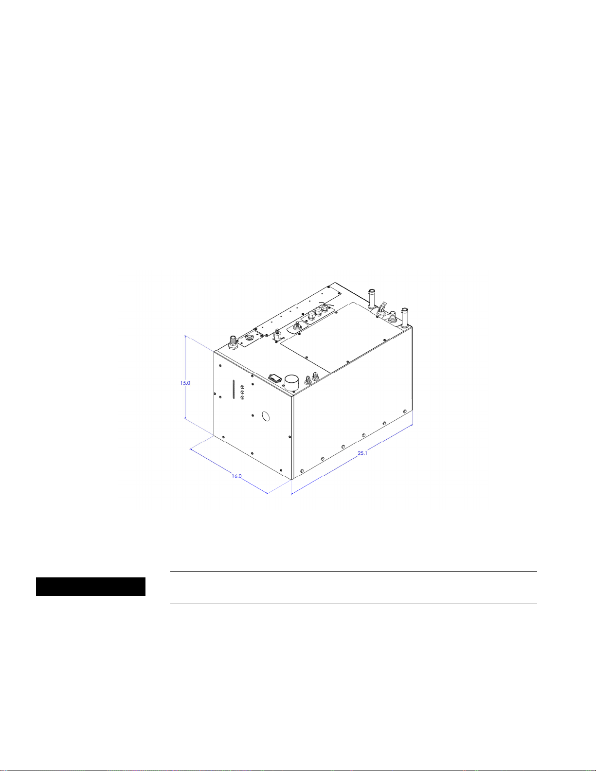
· Oasis® Chinook Heating System is 15”H x 16”W x 25.1” D.
(38.1 cm x 40.64 cm x 63.7 cm), see Figure 2-1: Oasis
Chinook Dimensions.
· Oasis® Chinook Heating System must be installed in a
compartment which is completely isolated from the atmosphere
of living spaces.
· Combustion air must be drawn from an outside source and
cannot contain any combustible gases.
· Mount the unit with the front panel facing out and accessible.
This mounting position simplifies installation and maintenance.
Leave the top of the unit accessible for maintenance.
2-2 The Oasis® Chinook Heating System
Section 2, Mounting the Oasis® Chinook Heating System
! DANGER
· The Oasis® Chinook Heating System must be mounted in an
area that provides unrestricted access to the front and top
panels. Allow space for connection to the fuel, coolant, and
potable water lines, as well as the power, exhaust, and air
intake connections. The following are the minimum required
clearances: 12” top clearance, 12" front clearance; 0” clearance
to all other Oasis® Chinook Heating System surfaces. Allow 1”
clearance on the left and right side for attaching the mounting
brackets.
· Oasis® Chinook Heating System must be mounted horizontal
and level using eight, 1/4” through bolts and 1” diameter
fender washers, lock washers and nuts.
International Thermal Research 2-3
Figure 2-1: Oasis Chinook Dimensions
Oasis® Chinook Heating System must not be installed or operated
in any compartment with flammable gases.

Section 2, Mounting the Oasis® Chinook Heating System
! WARNING
! D
ANGER
If the Oasis® Chinook Heating System is going to be mounted in
the engine compartment, check for adequate ventilation. When
the engine is running this area could be under a negative pressure.
Make sure the air-intake hose and exhaust pipe have no leaks and
are well fastened to the heater, muffler and thru-hull fitting.
Assembly parts that may cause injury through accidental contact
should be protected.
This is a direct vent system. The combustion air must be drawn
directly from the outside, without coming in contact with air that
can infiltrate the living areas. See section 3.3.
· It is recommended that a catch pan be placed under the Oasis®
Chinook Heating System to contain any unexpected leak.
· Choose a sturdy surface in a location that won’t be unduly
affected by vibration and jarring from rough roads.
· Ensure that the exhaust tubing can be properly and safely
routed to the outside. The maximum exhaust run for the
system is 12’, including 90 degree bends. See section 3.2.
2.4 What NOT to Do
· Don’t mount the Oasis® Chinook Heating System in the rear of
the coach, underneath the sleeping area. The sound of the
Oasis® Chinook Heating System cycling on and off may disturb
light sleepers.
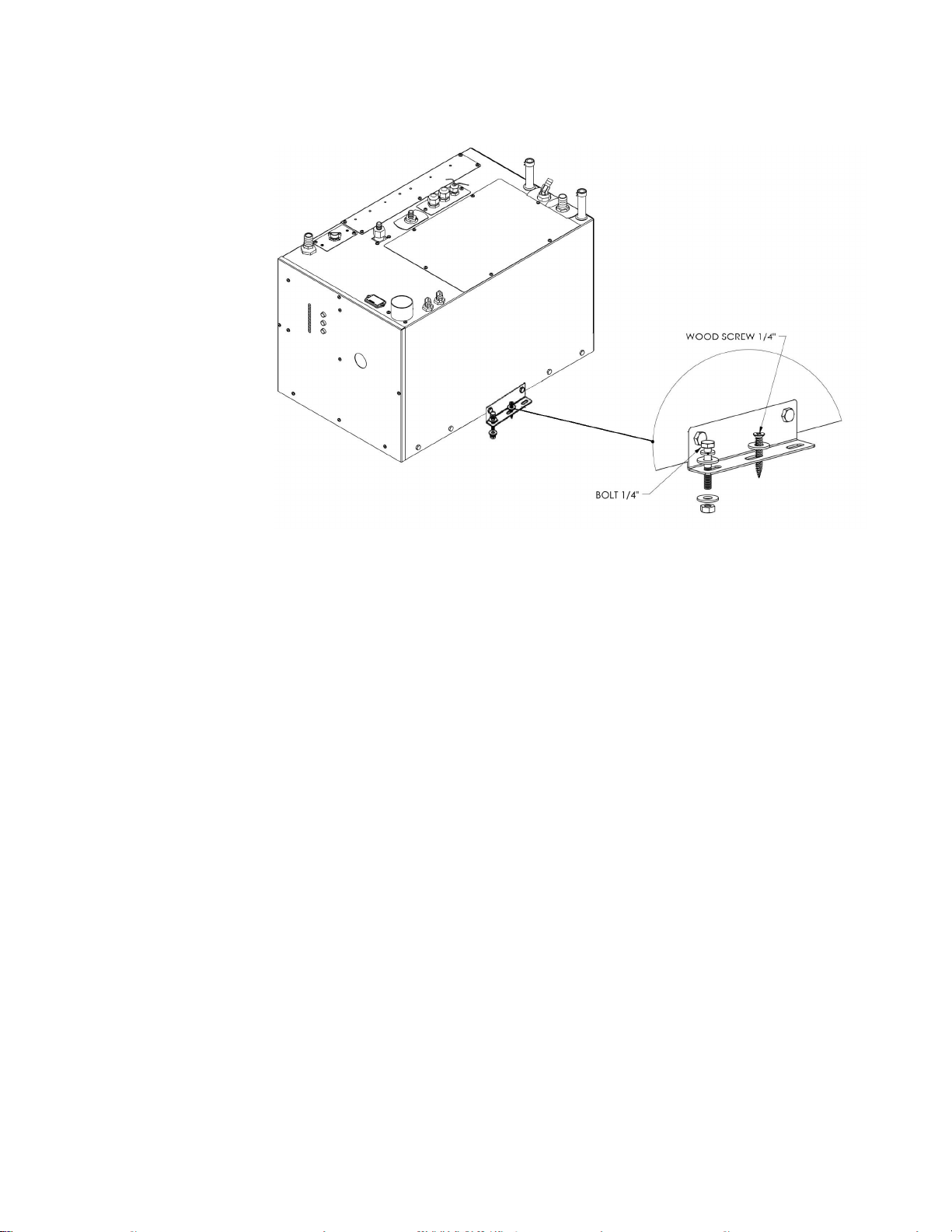
2.5 Oasis® Chinook Mounting Procedure
After choosing the mounting location for the Oasis® Chinook
Heating System, mount the unit and ensure it is level. Secure the
Oasis® Chinook Heating System in place (against the wall, floor or
a mounting platform) using four (4) mounting brackets, eight (8) x
1/4” through bolts (or wood screws), and 1” diameter fender
washers, lock washers, and nuts. (See Figure 2-2: Oasis Chinook
Mounting Brackets.).
2-4 The Oasis® Chinook Heating System
Section 2, Mounting the Oasis® Chinook Heating System
Figure 2-2: Oasis Chinook Mounting Brackets
2.6 Zone Control Board Mounting
Procedure
· Mount the Zone Control Box (containing the Zone Control
Board) vertically, close to the Oasis® Chinook. Allow sufficient
room to access the internal fuses as well as to view the display
LED’s on the front of the board.
· Mount the bracket against a wall using 2 flat head screws. The
distribution module zone box will then click onto the bracket.
See Figure 2-3.
International Thermal Research 2-5
Section 2, Mounting the Oasis® Chinook Heating System
Figure 2-3: Zone Control Board
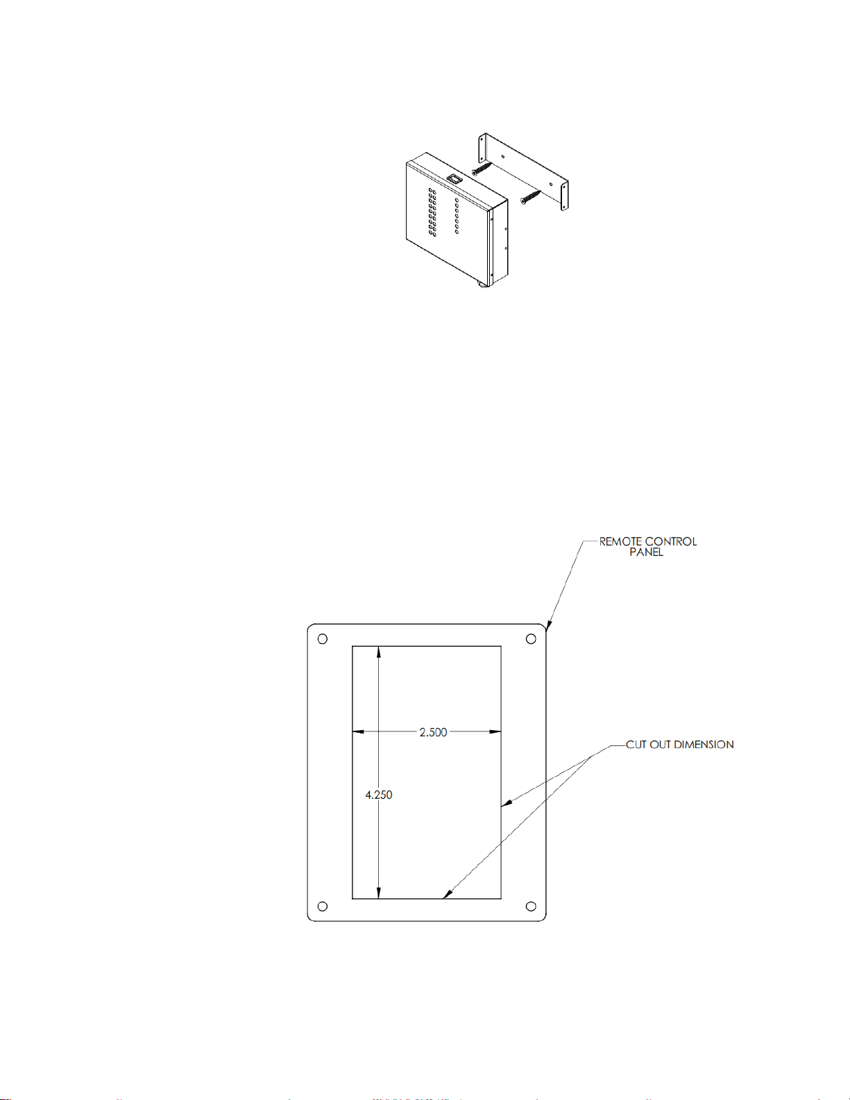
2.7 Remote Operating Panel Mounting
Procedure
The Remote Operating Panel is mounted inside the Coach, in an
easy to access location. An opening for the remote panel must be
cut in the wall or mounting panel. The Remote Operating Panel will
be screwed in place using the 4 mounting holes.
Figure 2-4: Basic Remote Operating Panel Mounting
2-6 The Oasis® Chinook Heating System
Section 2, Mounting the Oasis® Chinook Heating System
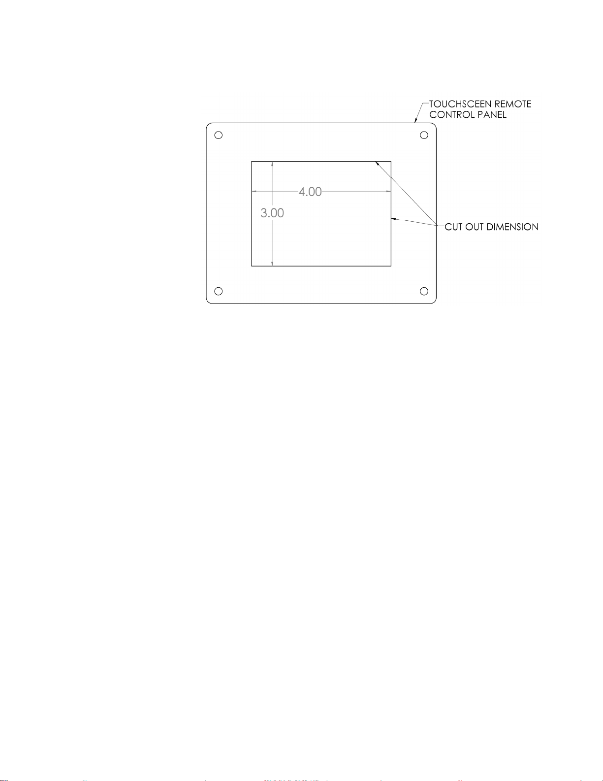
Figure 2-5: Touchscreen Operating Panel Mounting
International Thermal Research 2-7
Section
DANGER
3
Installing the Exhaust System
3.1 Before You Begin
For efficient and safe operation of the Oasis® Chinook Heating
System follow all recommendations for properly installing the
exhaust. Any deviations from these must be approved in advance
by ITR.
!
Although the heater’s exhaust produces very low carbon monoxide
emissions, caution is still advised:
· Do not operate the Oasis® Chinook Heating System in an
enclosed area unless there is adequate ventilation.
· This is a direct vent system. The combustion air must be
drawn directly from the outside, without coming in contact
with air that can infiltrate the living areas. See section 3.3.
Never place any exhaust parts close to combustible material or
through a combustible wall or ceiling without fireproof protection.
The exhaust can reach high temperatures.
3.2 Mounting Location
If you can’t meet the technical specifications for mounting
the exhaust, don’t use the Oasis® Chinook Heating System.
The unit may perform poorly or become damaged if not
installed according to specifications.
International Thermal Research 3-1
Recommended Exhaust Outlet Locations
The following is recommended for a coach exhaust outlet location:
· Mount the exhaust outlet outside the coach, not inside the
heater compartment. Otherwise, exhaust fumes could
infiltrate the coach from the Oasis® Chinook Heating System.

Section 3, Installing the Exhaust System
!
DANGER
· When mounting the Oasis® Chinook Heating System in a
coach, the typical mounting location for the exhaust outlet is
under the floor of the heater compartment and out from the
side of the coach, or out from the other side of the coach,
directly across from the heater. The Oasis® Chinook Heating
System will allow a maximum of 12' of exhaust piping,
without any bends (excluding the exit bend from the heater).
· Position the outlet of the exhaust pipe so that the exhaust
exits out from under the side of the coach, not directly
underneath the coach or under an opening window or vent.
· If the exhaust is mounted under a slide-out, the outlet of the
exhaust must be a minimum of 36" (inches) below the slideout, including skirt and moldings.
Recommendation for Installation
· You may use sweeping bends, but each 90° bend is
equivalent to two feet of exhaust piping. For example, if you
use two 90° bends, you must subtract 2' per bend from the
maximum allowed 12' exhaust length. Therefore, you will be
restricted to 8' of straight exhaust piping plus the two bends.
Do not exceed these recommendations.
· The combustion air must be drawn from outside the coach.
The maximum length of each air-intake tubing is 7 feet. Do
not exceed this recommendation.
· Use an ITR-manufactured muffler with a straight-through
design. No other muffler is acceptable.
· Exhaust outlet is on the bottom of the Oasis® Chinook
Heating System, towards the back.
The exhaust and outlet are HOT and the surrounding areas
must be thermally shielded and protected from the hot
surfaces and heat build-up by insulation. Nothing can
come into inadvertent contact with any part of the
exhaust system.
3-2 The Oasis® Chinook Heating System
· Exhaust must have a minimum of 3” (7.6 cm) clearance from
all surfaces.
· Ensure that the exhaust cannot be plugged or restricted.
 Loading...