

International Thermal Research CO32D, CO65D, CO85D, CO105D, CO45D Operator's Manual
HURRICANE
HEATING SYSTEM
OPERATOR'S MANUAL
HURRICANE
International Thermal Research Ltd.
Covered by U.S. Patent # 5,391,075
Copyright 2000, 2001, 2002, 2003
International Thermal Research Ltd.
is a registered trademark of
And other U.S. and foreign patents
and patent applications

INDEX
PAGE
1. INTRODUCTION & TECHN ICAL SPECIFICATIONS 1-1
1.1 FEATURES 1-2
2. COMPONENTS 2-1
2.1 COMPONENTS 2-1
2.2 OPTIONS AND ACCESSORIES 2-2
3. INSTALLATION 3-1
3.1 OVERVIEW 3-1
3.2 MOUNTING THE HEATER 3-1
3.3 LOCATION / ELEVATION REQUIREMENTS 3-2
3.4 EXHAUST SYSTEM 3-2
3.5 EXHAUST INSULATION 3-3
3.6 EXHAUST MUFFLER 3-3
3.7 THRU-HULL FITTINGS 3-3
3.8 AIR INTAKE TUBING 3-3
3.9 FUEL SYSTEM 3-4
3.10 AIR ACCUMULATOR 3-4
3.11 FAN HEATERS 3-5
3.12 BASEBOARD, TUBE & FIN 3-5
3.13 ELECTRICAL SYSTEM 3-6
3.14 CONTROL BOX 3-6
3.15 FUSES 3-6
3.16 REMOTE PANEL 3-8
3.17 THERMOSTAT WIRING 3-8
3.18 FAN HEATER WIRING 3-8
3.19 WATER SYSTEM 3-8
3.20 MOUNTING THE EXPANSION TANK 3-9
3.21 CIRCULATING WATER PUMP 3-9
3.22 RUBBER HOSE 3-10
3.23 AIR VENTS 3-10
3.24 SHUT-OFF VALVES 3-10
3.25 WATER FILLING PROCEDURE 3-11
3.26 CHECKING WATER CIRCULATION 3-12
3.27 DOMESTIC HOT WATER HEATING 3-12
4 USING A HEAT EXCHANGER 3-12
4.1.1 PROTECTING HYDRONIC HEATING SYSTEMS 3-14
4. OPERATION 4-1
4.1 STARTING THE HEATER 4-1
4.2 SIGNS OF NORMAL OPERATION 4-1
4.3 MAIN CONTROL BOARD OPERATION 4-2
4.4 STOPPING THE HEATER (FOR SEASONAL PURPOSES) 4-2
4.5 STOPPING THE HEATER (FOR MAINTENANCE) 4-2
4.6 RESETTING A FAULT 4-2
4.7 HEAT EXCHANGER OPERATION 4-3
4.8 DOMESTIC WATER OPERATION 4-3
4.9 ELECTRICAL NOISE 4-4
5. TROUBLESHOOTING 5-1
5.1 OVERVIEW 5-1
5.2 POWER ON (GREEN) 5-1
5.3 BURNER ON 5-1
5.4 SERVICE SWITCH OFF 5-1
5.5 REMOTE SWITCH OFF 5-2
5.6 HEATER CYCLING (NORMAL OPERATION) 5-2
5.7 THERMOSTATS OFF (NORMAL OPERATION) 5-2

5.8 VOLTAGE LOW OR HIGH 5-3
5.9 OVERHEAT 5-3
5.10 FUSE BLOWN 5-3
5.11 FUEL PUMP/SOLENOID 5-4
5.12 IGNITOR 5-4
5.13 COMBUSTION FAN 5-4
5.14 WATER PUMP 5-5
5.15 FLAME OUT 5-5
5.16 COMPRESSOR 5-6
5.17 BYPASS MODE 5-6
5.18 WATER PUMP ON (GREEN) 5-6
5.19 REMOTE PANEL 5-6
5.20 LCD READOUT REMOTE PANEL (OPTIONAL) 5-6
5.21 FLAME SENSOR MODULE 5-7
5.22 REDUCED OUTPUT 5-7
5.23 SMOKEY, SMELLY EXHAUST 5-7
5.24 A SILENT KILLER 5-8
6. MAINTENANCE 6-1
6.1 THE FIRST FEW WEEKS 6-1
6.2 ADDING ANTIFREEZE 6-1
6.3 MARINE EXHAUST SYSTEM 6-1
6.4 NOZZLE 6-2
6.5 FUEL LINES AND FILTER 6-2
6.6 COMBUSTION CHAMBER 6-2
6.7 CHECKING HOSES AND TUBES 6-2
6.8 ELECTRICAL SYSTEM 6-3
6.9 RECOMMENDED SPARE PARTS 6-3
7. WARRANTY AND SERVICE 7-1
7.1 WARRANTY 7-1
7.2 INSTALLATIONS 7-1
7.3 LIMITED WARRANTY 7-1
7.4 OWNER’S RESPONSIBILITIES 7-2
7.5 NOT COVERED UNDER WARRANTY 7-2
7.6 CUSTOMER SERVICE CALLS 7-3
7.7 RETURNS 7-3
7.8 TELEPHONE SERVICE 7-4
8. PARTS 8-1
8.1 PARTS LISTING 8-1
8.2 PARTS LISTING 8-2
8.3 HEATER ASSEMBLY 8-3
8.4 COMPONENT BOX ASSEMBLY 8-4
8.5 WATER JACKET AND BURNER BOX ASSEMBLY 8-5
8.6 BURNER TUBE ASSEMBLY 8-6
8.7 COMBUSTION FAN ASSEMBLY 8-7
8.8 FUEL PUMP ASSEMBLY 8-8
LIST OF FIGURES
FIGURE 2-1: COMPONENT PARTS 2-7
FIGURE 2-2: TYPICAL INSTALLATION 2-8
FIGURE 3-1: WIRING DIAGRAM FOR ELECTRONIC CONTROL BOX 3-7
FIGURE 3-2: OPTIONAL DOMESTIC WATER HOOKUP 3-13
FIGURE 6-1: MAINTENANCE SCHEDULE 6-4
FIGURE 8-1: HEATER ASSEMBLY 8-3
FIGURE 8-2: COMPONENT BOX ASSEMBLY 8-4
FIGURE 8-3: WATER JACKET AND BURNER BOX ASSEMBLY 8-5
FIGURE 8-4: BURNER TUBE ASSEMBLY 8-6
FIGURE 8-5: COMBUSTION FAN ASSEMBLY 8-7
FIGURE 8-6: FUEL PUMP ASSEMBLY 8-8

THE LATEST TECHNOLOGY IN A DIESEL HOT WATER HEATING SYSTEM
HURRICANE
The HURRICANE heater is constructed of a stainless steel case which houses all the working
components. The water jacket is made of copper and brass for efficient heat transfer and brazed
together for durability and long life. The deluxe model includes a fully insulated water jacket, for
minimum heat loss, and extends the stainless steel casing for a completely enclosed heater. The burner
and combustion tube are made of a special high temperature stainless steel to prevent premature
warping or burnout.
The HURRICANE heater utilizes a low pressure fuel system. The built in fuel pump draws fuel from
the fuel tank up to a zero pressure regulator where it stops. An air accumulator is installed inline
between the fuel pump and the regulator to trap any air bubbles from passing through the nozzle
causing nuisance shutdowns. The accumulated air can be periodically bled off through the bleeder
valve. For continuous bleeding, a return line can be run back to the fuel tank. A small compressor
delivers air to an air aspirating nozzle. This nozzle draws fuel from the zero pressure regulator, mixing
it with air through a venturi. This process produces a very fine mist of fuel into the burner providing
complete combustion and very low emissions. This low pressure system allows the use of a larger fuel
orifice, less clogging, less wear and less maintenance. Ignition is accomplished by a low draw ignitor,
approximately 2 amps, for thirty seconds. A small fan provides outside air for combustion and a
positive exhaust flow through a single thru-hull fitting. Combustion air is drawn from outside so the
heater can be installed in an air tight compartment or in the engine room without the fear of starving the
heater of air or back venting the heater with the engine running.
A main control panel times all the heater functions, monitors the operation of each component and
provides a safety shutdown of the heater should anything go wrong. It provides for four space heating
zones, a domestic water heating zone, and a thermostat hookup when using a water to water heat
exchanger. A heat exchanger will give you the ability to transfer waste heat from your engine to your
heating system. Conversely, you can keep your engine warm when your heating system is operating.
Extra space-heating zones are available for individual cabin control.
A remote control panel is provided as standard equipment. The remote panel has an on/off reset switch
and a LED digital readout, for indication of normal or fault operations respectively. A signal beeper on
the remote panel serves as an audible indication of a fault causing a shutdown situation.
The HURRICANE heater is very user friendly and easy to install. It is normally built with all
connections (fuel, air, exhaust, and water) off the top of the heater and the component box on the left
side. The heater can also be ordered with bottom connections and or with right side components. If
access to the heater is unrestricted, any part can be removed and replaced within 30 minutes.
This publication was correct at the time of printing. ITR has a policy of continuous improvement in its products and
reserves the right to amend any specifications or procedures without prior notice.
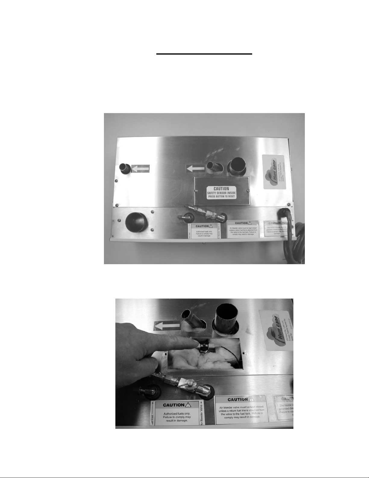
IMPORTANT NOTICE
The Hurricane heater now has an additional secondary safety shut off feature. A high
temperature, overheat aquastat as shown in the pictures below. This aquastat is a manual reset
only type, and if tripped, should not be reset until an authorized ITR dealer or service
representative has examined the heater.

CHAPTER 1
INTRODUCTION AND TECHNICAL SPECIFICATIONS
Congratulations on the purchase of your new ITR HURRICANE heater.
This manual should tell you the basics of what you need to know for a proper installation, operation,
and maintenance of your heater. ITR or your local HURRICANE dealer are available to help with
installation and maintenance, and to answer your questions. Your local HURRICANE dealer can
supply you with any accessories needed to install the heater. See Chapter 7 for information on our
warranty and customer service, and how to contact us.
The HURRICANE heater is currently available in five capacities:
Technical Specifications
MODEL BTUH
Input
CO32D
CO45D
CO65D
CO85D
CO105D
32,000 4.0 0.20 2
45,000
65,000 0.75" or
85,000 11.0 0.60 6
105,000
WATER
Connection
EXHAUST
Outlet
US GAL
Capacity
0.75" 1.50” 1.0
2.0" 1.25 6 0.45 4 10"x15"x29.0"
1.50”
1.50" 2.0" 2.50
AMPS FUEL
GAL/H
MIN
FLOW
GPM
6 0.30 3
13.0 0.75
7
O.D.
h x w x d
(Wt - lbs)
7”x11"x19.0"
(37)
(75)
10"x15"x29.0"
(75)
MODEL CO45D MODEL CO105D

1.1 FEATURES
Designed for the marine and RV environment, the HURRICANE heater features unique, state of the art
technology. Special features of the HURRICANE heater include:
• Fuel efficient burner which burns all grades of diesel fuel, stove oil, furnace oil, and kerosene
without any burner adjustments (not for use with gasoline)
• Zero smoke, no carbon build-up, no fouling or smell
• Copper and brass water jacket transfers more heat to the water and reduces the fuel consumption
(three year warranty)
• High temperature 310 stainless steel burner and marine stainless steel jacket
• Quiet operation and low power consumption
• All heaters are designed to operate on 10.5 to 15.0 V.D.C.
• All heaters are electric ignition, which draws 2 amps for 30 seconds on startup
• Insulated enclosure for retaining heat and minimizing noise
• Sealed combustion – 100% outside air is fan assisted to the combustion chamber and then
exhausted outside, avoiding back pressure
• Includes four zone heating control for up to four thermostats
• Completely modular and field serviceable (user friendly)
• Hookups and connections are easily accessible
• Electronically controlled. Safety features include four second shutdown in case of failure, LED
digital readout on the electronic control panel for indicating faults, aquastats for monitoring water
temperatures and a flame sensor to monitor the flame
• Complete with remote control panel with ON/OFF reset button, LED digital readout, and signal
horn
• Jumper for constant pump circulation ( Automatic cycling when off)
• All heaters cycle at an operating temperature of 180°F (82°C) with overheat cutout set at 195°F
(90.5°C)
• Air accumulator installed in the fuel line to collect air bubbles and prevent them from reaching
the burner and causing nuisance shutdowns
The HURRICANE Hydronic Heating Systems have been tested to UL 307A "Liquid Fuel-Burning
Appliance for Manufactured Homes and Recreational Vehicles" and is listed by Testing Engineers
International Inc. - Listing Services (TEI - LS) for Recreational Vehicle and marine use.
CHAPTER 2
2.1 COMPONENTS
Below is a description of the parts that come with the basic ITR HURRICANE heater. Before you start
the installation, make sure you have all of the components and ARE FAMILIAR WITH ALL
ASPECTS OF THIS MANUAL.
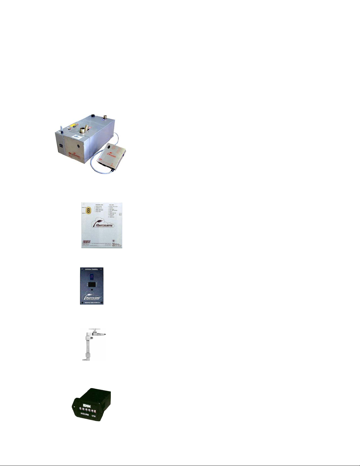
• HEATER – includes a fuel pump, air accumulator, combustion air fan, compressor, regulator, fuel and
air nozzle, burner, combustion chamber, and water jacket. Figure 2-1 at
the end of this chapter shows a cross-section of a heater, with all the
component parts and includes an insulated water jacket and a complete
wrap around stainless steel cover. A ten foot long multi-conductor able is
prewired to the heater and plugs into the electronic control board.
• ELECTRONIC CONTROL BOARD – consists of a service switch, a jumper for a constant
circulation pump, fuses, terminal connections, circuit board, a fault
indicator LED digital readout from which you can monitor the entire
operation of the heater. The circuit board allows four zone hookup of
four thermostat, one Domestic Water Aquastat, one Heat Exchanger
Aquastat, one water pump ( maximum 10 amps total ), and Cabin Fan
Heaters (maximum 10 amps total).
• REMOTE PANEL INDICATOR – An ON / OFF - RESET switch with a LED digital readout and
signal horn. Includes a cable that allows you to connect the remote
indicator panel up to 25’ away from the heater itself.
• AIR ACCUMULATOR – A tube with a bleeder valve eliminates nuisance shutdowns due to air
bubbles in the fuel line. A return air line can be run back to the tank for
automatic bleeding. See page 3-4 for more information.
• HOURMETER – The hour meter will provide you with the accumulated operating hours for your
HURRICANE heater. Regular inspection and maintenance of the heater
and its associated components should be performed to keep it in peak
operating condition.
2.2 OPTIONS AND ACCESSORIES
HURRICANE options and accessories are available from selected ITR Dealers and Service
Centres. Call ITR for an authorized dealer near you.
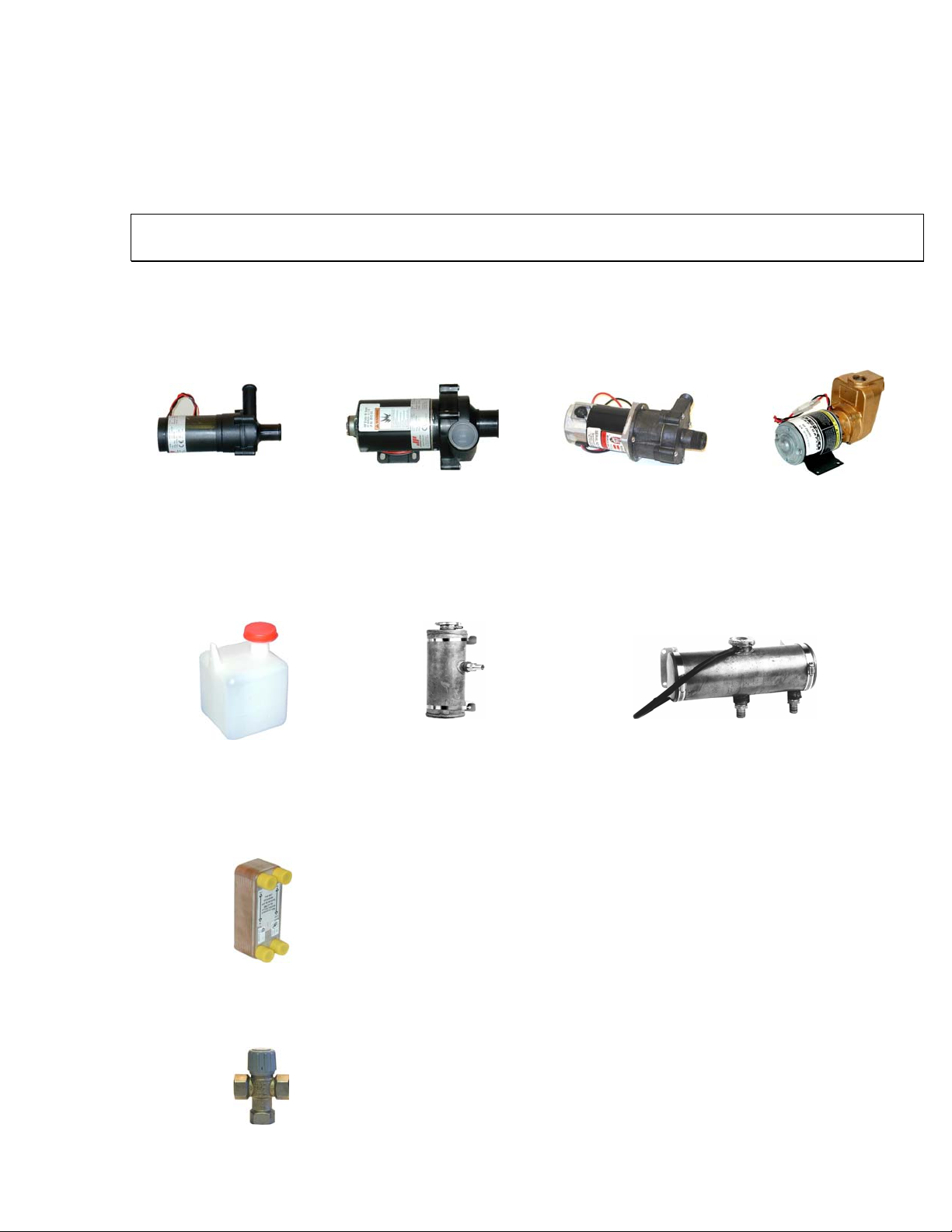
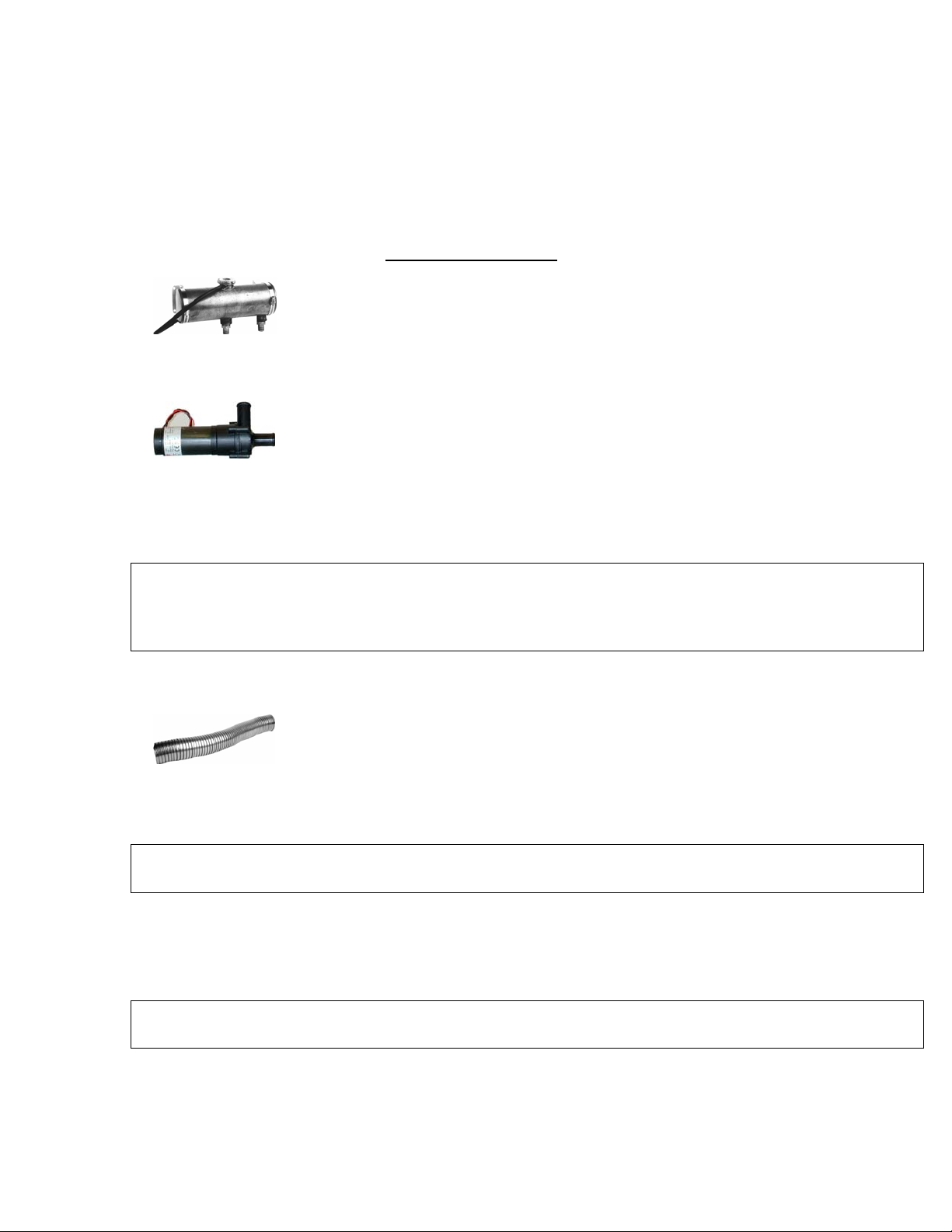
• WATER PUMP - These pumps circulates water through the system. It must be sized to a flow rate and
head capacity. See circulating water pump, page 3-9.
• EXPANSION TANK - This tank is required to fill the heating system and allow for expansion. An
automotive type overflow tank, part # 20021, should be connected to the filler neck of the tank for larger
system capacities. Part # 20002: vertical, 5”W X 5 ½”D X 13”H (12.7cm X 14cm X 33cm) Part #
20001: horizontal, 12”W X 4 ½”D X 7”H (30cm X 11.4cm X 17.8cm)
• WATER TO WATER HEAT EXCHANGER – this device recycles waste heat from your engine and
transfers it to the HURRICANE heater. The heater can also be used to pre-heat your engine. A second
heat exchanger can be used to boost the temperature of your domestic hot water supply. (part # 5130). A
double wall unit is available for the heating of potable water.
• MIXING VALVE - This valve is an anti-scald, proportional thermostatic water mixing/diverting valve
with temperature lock at any setting. Fittings are 1/2" NPT and the temperature rating of the valve is 90°
to 120°F.
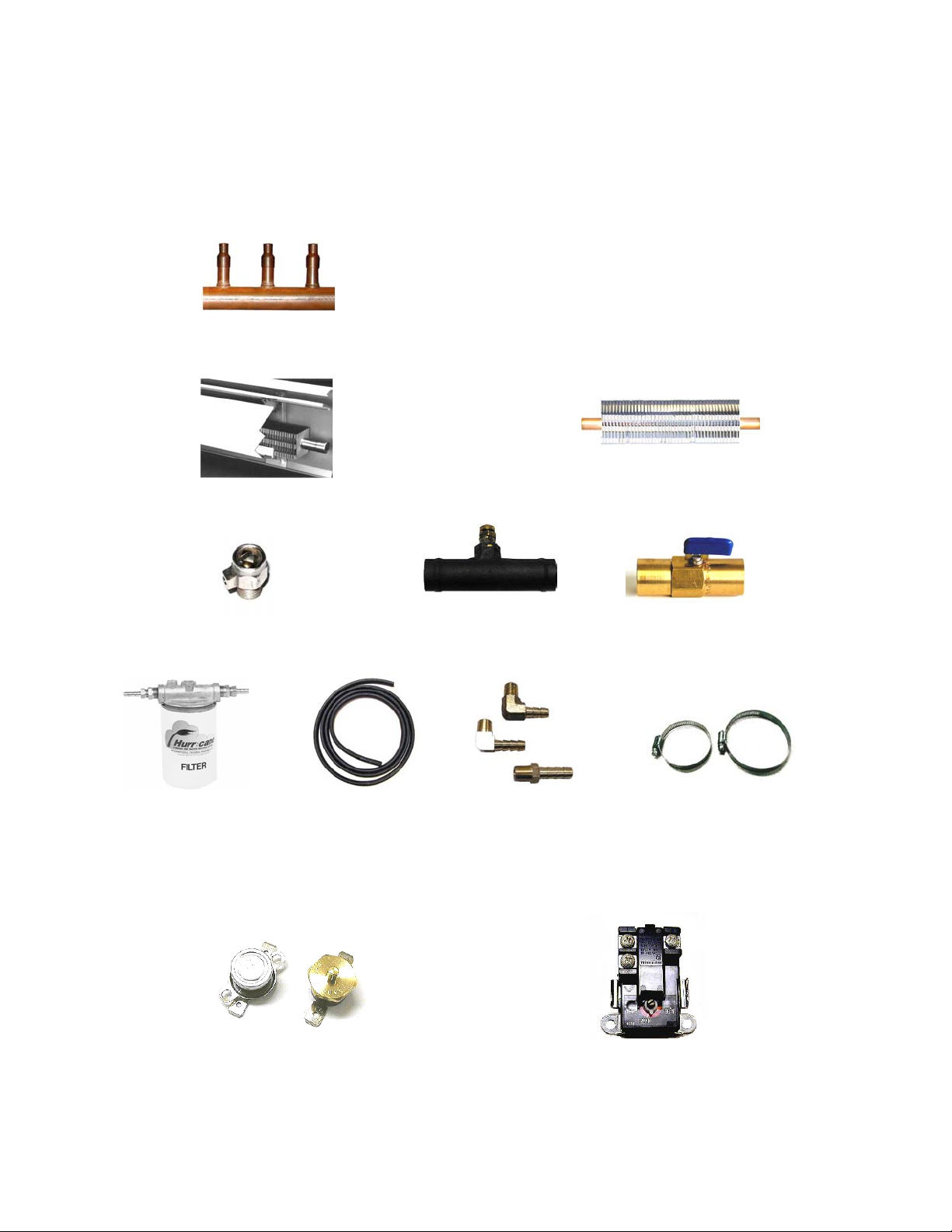
• COPPER MANIFOLDS
For larger installations, 2 or 3 loops are used to reduce the resistance of water flow and to distribute heat
more evenly in each zone. See 3.21, circulating water pump, page 3-9.
• BASEBOARD / FIN AND TUBE
• AIR VENTS / BLEEDER ASSEMBLY / VALVES
• FUEL FILTERS / FUEL LINE AND FITTINGS
• AQUASTATS - Provides automatic control of domestic water heater ( w-w terminals) and automatic
utilization of waste engine heat.
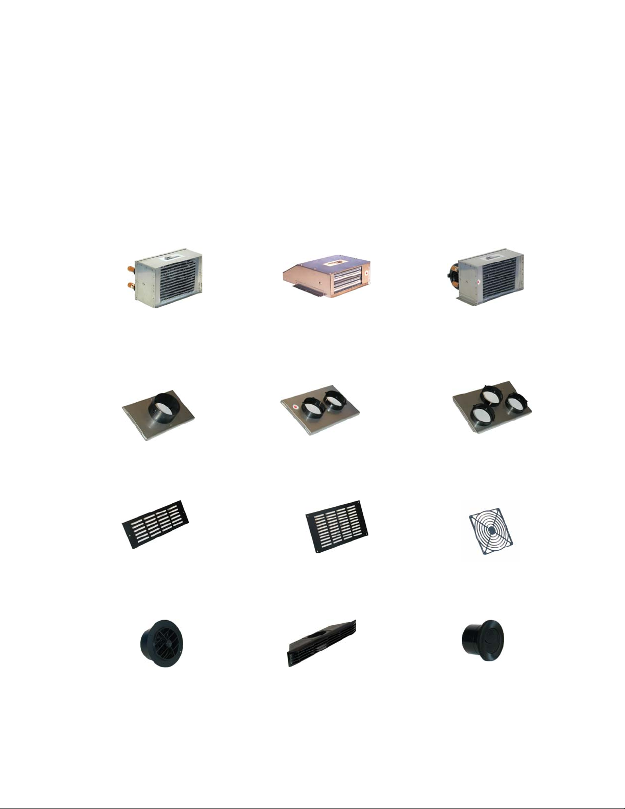
• FAN HEATER – Constructed of a copper core and stainless steel enclosure, these heaters provide up to
10,000 Btuh (2.9kW) of hot air. The Cabin and Spacesaver Heaters produces up to 140 cfm. and draws a
minimal amount of current (.9 amps). The fan can be cycled thermostatically to allow regulation of the
amount of heat delivered to a particular area. An integral aquastat prevents the fan from coming on until
the heater has warmed up enough to eliminate the circulation of cold air. The Defrost Heater, provides up
to 28,000 BTUH and uses a three speed fan, 200/275/450 CFM, 40/55/100 watts. All of the above fan
heaters can also run directly off the engine and provide heat whenever the engine is running.
Cabin Heater part # 6002: 6”H X 10”W X 6”D (15.5cm X 25.5cm X 15.5cm)
Spacesaver Heater part # 6034: 3 1/2"H X 9"W x 11 3/4"D (9cm X 23cm X 30cm)
Defrost Heater part # 6048: 6"H X 10"W X 9"D (15.5cm X 25.5cm X 23cm)
CABIN SPACESAVER DEFROST
• AIR OUTLET PLATES – These plates allows you to modify our cabin heater and the cabin defrost
heater to permit ducting of warm air to one, two, or three separate outlets. Available in 3” and 4”
combinations.
#1014 #1007 #1056
• AIR OUTLET GRILLS
#1057 #1049 #6035
#1017 #1009 #1051
• THERMOSTAT – The HURRICANE heater can be controlled by up to four thermostats. They have
a range of 50°F to 90°F with an OFF position.
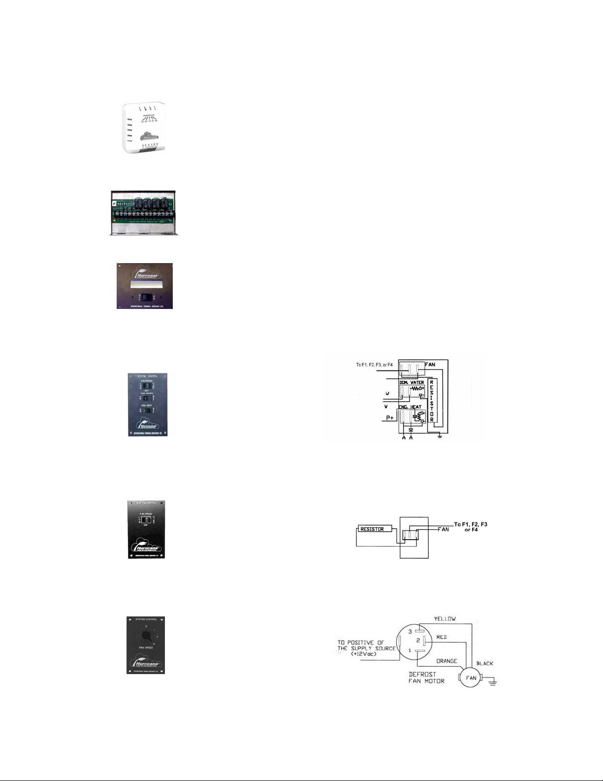
• ZONE CONTROL BOARD – gives you the option of running an additional 4 thermostatically
controlled zones for fan heaters up to 10 amps maximum (part # 2014). Stainless
Steel box for mounting is also available (part # 2012).
• LCD READOUT REMOTE PANEL - This panel will display the diagnostic explanation which will
match up to the diagnostic code on the main board. A small buzzer will sound for
10 seconds to alert you of a fault (part # 2004).
• SYSTEM CONTROL SWITCH PLATE - Combination, fan speed, domestic water and engine heat
rocker switches (part # 5067)
• TWO SPEED FAN SWITCHES - Low and high speed fan switch for extra quiet operation in
staterooms (part # 5068). For use with the Cabin Heater #6002 and the Spacesaver Heater #6034.
• THREE SPEED FAN SWITCH - Low, medium, high fan switch, part # 5106 for use with
Defrost Heater #6048.
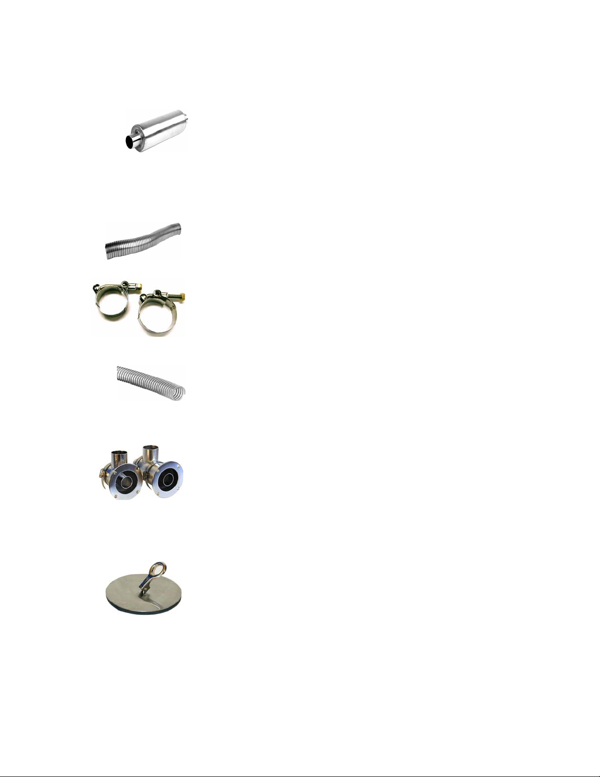
• EXHAUST MUFFLER – Constructed of stainless steel and packed with ceramic insulation. The
straight through design eliminates any backpressure and reduces
exhaust noise by up to 50% (part # 13008 - 1 ½”, 13009 - 2”). Also
available in cold rolled steel. (part # 13006).
• EXHAUST PIPE – Flexible stainless steel exhaust pipe will allow you to connect the heater to the thru-
hull exhaust fitting. The hose is flexible and allows you to easily route the exhaust around corners or
other difficult situations. See page 3-2 for installation details. (part # 5134 - 2”
(52mm) o.d., 5133 - 1 ½” (38mm) o.d. Insulating heat sleeve is available to
prevent burns from contact with the exposed hot exhaust pipe. (part # 5136 2”, 5135 - 1 ½”). Good quality T clamps should be used on all exhaust
connections
• AIR INTAKE FLEXIBLE TUBING – Allows you to connect the heater to the thru-hull fitting
providing outside combustion air for a sealed combustion system. See page 3-3
for installation details. (part # 8019)
• THRU-HULL EXHAUST /INTAKE FITTING – Consists of a 2”(52mm) or 1 ½”(38mm) exhaust
outlet and a 2” air inlet, providing a balanced system for the heater. Short and
long sizes available for various hull thicknesses.
• THRU HULL PLUG - Stainless Steel to fit 1 1/2" and 2" Exhaust / Intake Thru Hulls ( page 6-1)
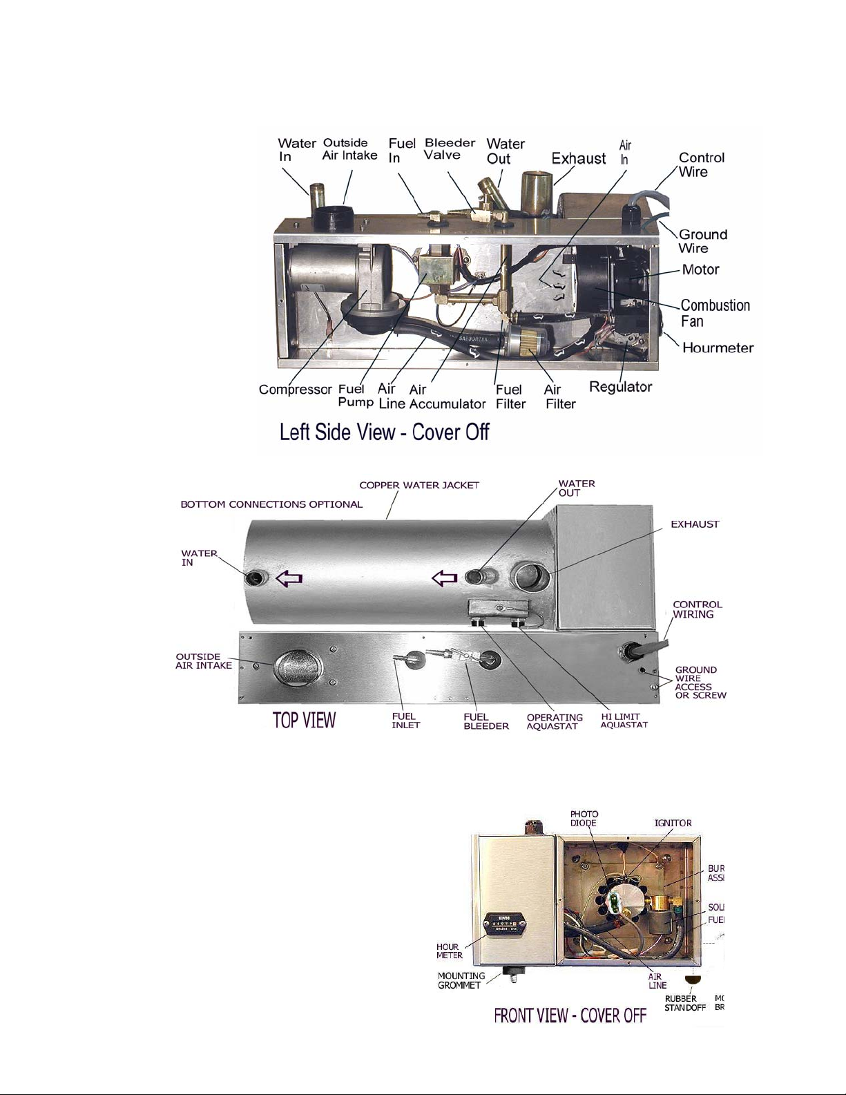
Figure 2-1
Component Parts
- CO Model
See Chapter 8 for complete
Parts Listing
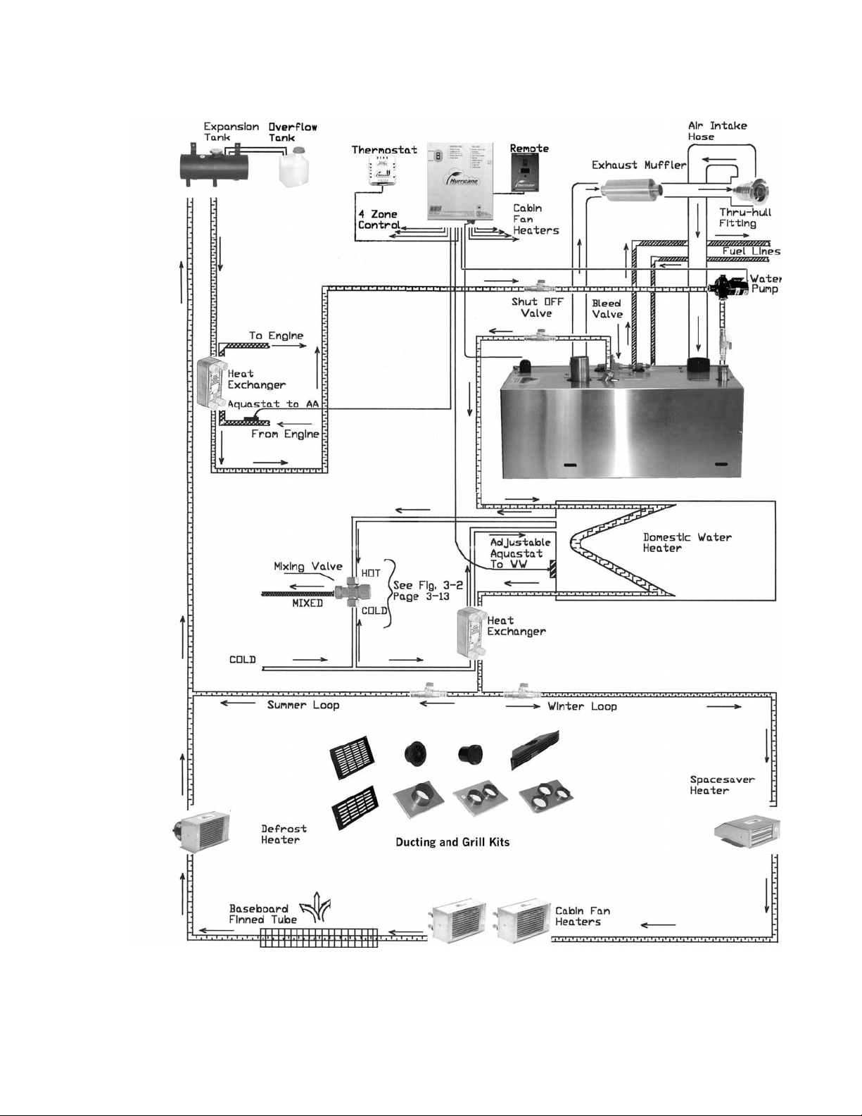
Figure 2-2 Typical Installation

CHAPTER 3
INSTALLATION
3.1 OVERVIEW
Installation of the HURRICANE heater is best done with some mechanical aptitude and electrical
knowledge. It is a central hot water heating system, similar to what you might have in
your home. Critical factors include sizing of the circulating pump, routing of the water
lines, purging of water and fuel lines and installation of the electronic control box,
among others. See fig. 2-2, page 2-8 for a typical installation.
A properly designed and installed system is essential to ensure that the customers receive
satisfactory results, and a warm, comfortable environment. The following is a basic guideline to
the entire heating system and will vary with every application.
ITR can only guarantee the HURRICANE heater if the entire system has been sized and installed
by our approved dealers, or alternatively, if ITR or the dealer reviews and approves the system
design both prior to and after the installation.
Systems installed without dealer approvals will be limited to a 90 day or 250 hours of operation
warranty. See Chapter 7 for warranty details before installing your system.
3.2 MOUNTING THE HEATER
The heater’s physical size allows it to be mounted in a very small area that may be difficult or nearly
impossible to access. For normal servicing, access to the front, left side, and top must be provided. The
HURRICANE heater can also be ordered with bottom connections and/or front/right side access.
Choose a sturdy side wall or a mounting location that will not be affected by the heavy jarring and
movement experienced by a boat in rough seas or a vehicle on rough roads.
You must consider the weight of the heater (full of water) when selecting a mounting location and
mounting equipment. Keep in mind the exhaust run from the heater which may limit the mounting
location. Ensure that the exhaust tubing can be properly and safely routed to the outside.
The heater comes with rubber mounting grommets installed, two installed in the bottom of the
component enclosure box and one or two in separate brackets with self adhesive rubber standoffs. A
screw or bolt with a washer (not included) must be used through the center of the grommet to secure
the heater in place.
If the heater is going to be mounted in the engine compartment, check for adequate ventilation. When
the engine is running, this area could be under a negative pressure. Make sure the air intake and
exhaust hoses have no leaks and are well fastened to the heater, muffler, and thru-hull fitting. Assembly
parts that may cause injury through accidental contact should be protected.
3.3 LOCATION/ELEVATION REQUIREMENTS
When planning space requirements for the HURRICANE system, remember:
The expansion tank must be the highest elevation point in the system so that air can be easily expelled
and water can flow directly down to the water pump. Mount the heater and all
other parts of the system at a lower point than the expansion tank. An automotive
type overflow tank is recommended off the expansion tank, part # 22001. This
also provides a visual check of the coolant level.
The water pump must be mounted at the lowest point or in a location that ensures it will always be
flooded and will not trap air. The pump must never be allowed to run dry. Check
the manufacturer’s recommendations. Make sure hoses can be installed without
kinks which will restrict water flow.
3.4 EXHAUST SYSTEM
If the standards for mounting the exhaust system cannot be met, do not use this heater. Do not
exceed these limitations. The exhaust system of this heater produces very little emissions of
carbon monoxide, but caution must still be used. Do not operate the heater while in an enclosed
shelter, unless there is adequate ventilation.
The exhaust system tube must be extended from the exhaust outlet of the heater to the thru-hull exhaust
fitting located as high above the boat’s water line as possible and preferably
mounted on the transom of the boat. This location lessens the chance of the
exhaust gases contacting combustible material such as a pier or rafted boat. On
vehicles, the exhaust should be routed in the same direction as the engine exhaust.
Never terminate the exhaust directly beneath the vehicle. Heavy duty exhaust clamps should be used to
connect the exhaust tube to the heater, muffler, and the thru-hull exhaust fitting.
No more than 12 feet (3.7 meters) of exhaust tubing and no more than 360° of total bends, should
be used on the exhaust system. Do not use mufflers that have any restrictions to flow.
Since the HURRICANE heater can produce exhaust temperatures in excess of 400°F (204°C), the
exhaust system must be properly installed to approved ABYC standards, leaving suitable air spacing
and using metal shields or insulation where required to protect combustible materials.
Never place any exhaust system parts close to combustible material or through a combustible
wall or ceiling without fireproof protection.
 Loading...